

Page 1

INSTALLATION INSTRUCTIONS FOR
SOLID VENT KIT PART NUMBER
239-47811-00
The vent-air intake system must be properly installed. Failure to properly
install the vent-air intake system could result in property damage,
personal injury or death.
DO NOT install any damaged vent-air intake system components.
Contact the manufacturer of the water heater for replacement parts.
This vent kit is designed to bring all air for combustion from the outside and
vent all the combustion products to the outside when properly installed.
This vent kit should only be used with direct vent water heaters that were
designed to use this vent kit. Refer to the label on the water heater to
determine if this kit is the correct kit for the water heater that you are
installing. Consult the supplier of the water heater if you are not certain
that this is the correct vent kit. Refer to the information in these
instructions and the instructions provided with the water heater when
determining the location of the vent terminal and water heater.
The vent system must terminate so that proper clearances are maintained
as cited in local codes or the latest edition of the National Fuel Gas Code
ANSI Z223.1 as follows:
1. Do not terminate near soffit vents or crawl space or other area where
condensate or vapor could create a nuisance or hazard or cause
property damage.
2. Do not terminate the exhaust vent terminal where condensate or vapor
could cause damage or could be detrimental to the operation of
regulators, relief valves, or other equipment.
3. Do not terminate the exhaust vent terminal over public area or
walkways where condensate or vapor can cause nuisance or hazard.
4. The vent shall terminate a minimum of 12 inches above expected
snowfall level to prevent blockage of vent termination.
Vent pipes serving direct vent appliances are classified by building codes as
“vent connectors”. Required clearances from combustible materials must be
provided in accordance with information in this manual under LOCATION OF
WATER HEATER and CLEARANCES, and with National Fuel Gas Code
and local code
WARNING
,
238-48166-00A REV 7/09
Page 2
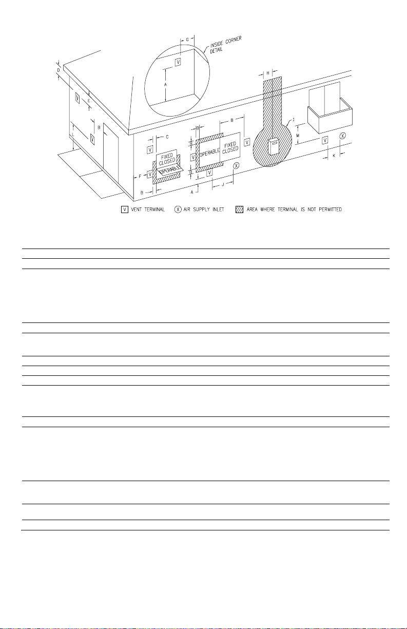
Figure 1
Direct Vent Terminal Clearances
Canadian Installations1 US Installations2
A= Clearance above grade, veranda, porch, deck or balcony 12 inches (30 m) 12 inches (30 cm)
B= Clearance to widow or door that may be opened 12 inches (30 m)
C= Clearance to permanently closed widow *b *b
Vertical clearance to ventilated soffit located above the
D=
terminal within a horizontal distance of 2 feet (61 cm) from
the center line of the terminal
E= Clearance to unventilated soffit 12 inches (30 cm) *a 12 inches (30 cm) *a
F= Clearance to outside corner *b *b
G= Clearance to inside corner *b *b
Clearance to each side of center line extended above
H=
meter/regulator assembly
I= Clearance to service regulator vent outlet or oil tank vent 36 inches (91 cm) *b
Clearance to non-mechanical air supply inlet to building or
J=
the combustion air inlet to any other appliance
K= Clearance to a mechanical air supply inlet 6 feet (1.83 m)
Clearance above paved sidewalk or paved driveway
L=
located on public property
M= Clearance under a veranda, porch, deck, or balcony 12 inches (30 cm) ‡ *b
1
In accordance with the current CAN/CGA-B149 Installation Codes.
2
In accordance with the current ANSI Z223.1-(Latest edition)/NFPA 54 National Fuel Gas Code.
12 inches (30 cm) *a
3 feet (91 cm) within a
height 15 feet (4.6 m)
above the meter/regulator
assembly
12 inches (30 cm)
7 feet (2.13 m)† *b
† A vent shall not terminate directly above a sidewalk or paved driveway that is located between two
single-family dwellings and serves both dwellings.
‡ Permitted only if a veranda, porch, deck or balcony is fully open on a minimum of two sides beneath the
floor.
*a) A minimum clearance value determined by testing in accordance with section 2.20.
*b) “Clearance in accordance with local installation codes and the requirements of the gas supplier”.
9 inches (23 cm) for
appliances > 10,000
Btuh (3 kW) and ≤
50,000 Btuh (15
kW), 12 inches (30
cm) for appliances >
50,000 Btuh (15
12 inches (30 cm)
*a
*b
9 inches (23 cm) for
appliances > 10,000
Btuh (3 kW) and ≤
50,000 Btuh (15
kW), 12 inches (30
cm) for appliances >
50,000 Btuh (15
3 feet (91 cm) above
if within 10 feet
horizontally
2
Page 3
IMPORTANT – Refer to parts list in the back of this manual
and become familiar with the parts named in kit.
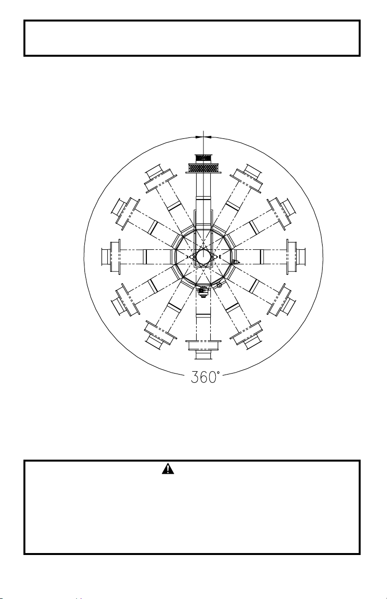
The co-axial vent-air intake tubes of this water heater can be installed in any
360° configuration as long as the proper clearances for installation,
plumbing, operation and servicing are maintained. (See Figure 2).
Figure 2.
Note: Maintain proper clearances for installation, plumbing, operation
and service.
WARNING
The vent-air intake system must be properly installed. Failure to properly
install the vent-air intake system could result in property damage,
personal injury or death.
DO NOT install any damaged vent-air intake system components.
Contact the manufacturer of the water heater for replacement parts.
3
Page 4
HORIZONTAL AND VERTICAL VENT-AIR INTAKE LENGTHS
Optional vent-air intake kits are available that can extend the horizontal
length and/or vertical height of the vent-air intake system. Table A lists the
various vertical and horizontal vent air-air intake system configurations.
The following components are found in the standard vent and air intake kit,
P/N 239-42979-00 (kit H). This kit, as well as all optional vent and air intake
kits must be ordered separately from the manufacturer shown on the rating
plate.
4” Vent Tube* Vent Terminal Hardware
6” Air Intake Tube RTV Silicone Sealant
Vent Terminal 4” Vent Elbow
Inner Wall Term. Mounting Flange 6” Air Intake Elbow
Outer Wall Term. Mounting Flange
• The vent and air intake telescopes from 13 3/4” to 23 11/16”.
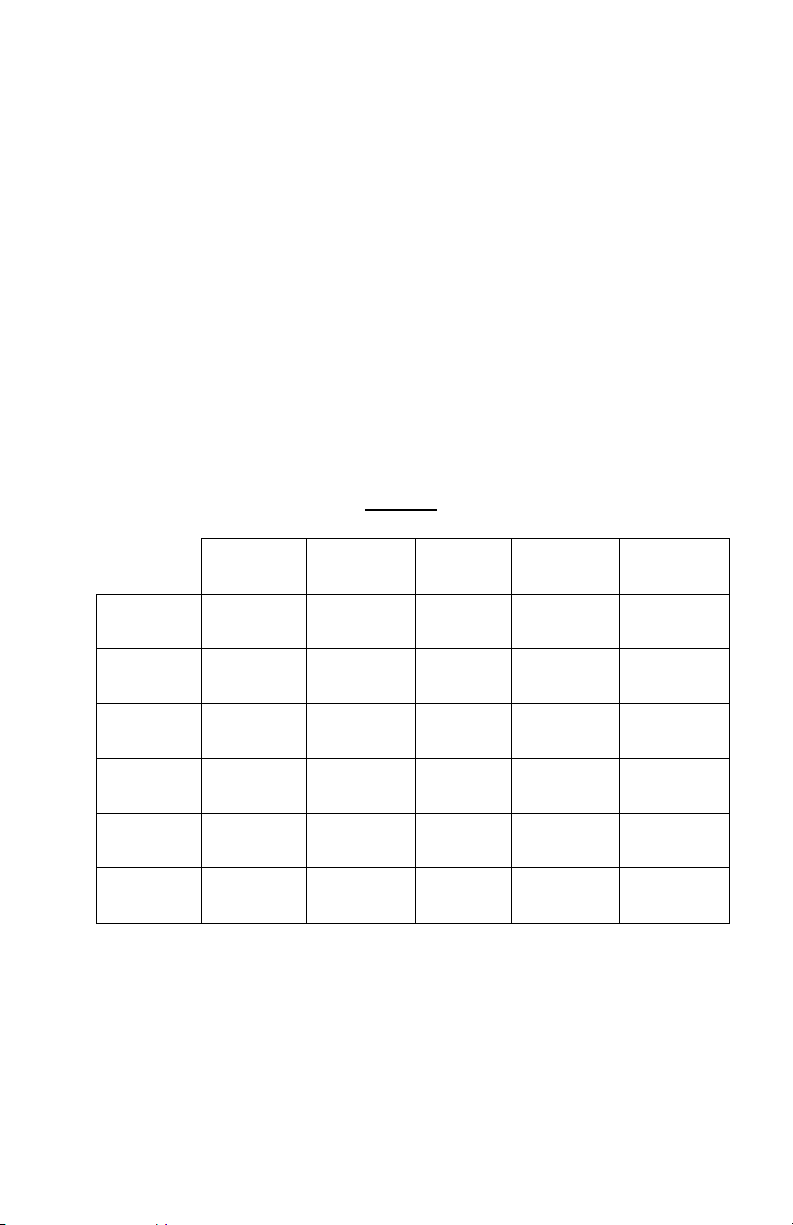
Table A
Horizontal "X"
Vertical "Y"
11 9/16
16 5/16 *order order
17 1/4 kit F (2) kit G & F
18 1/16 order order
20 3/4 kit F & G kit G (2)
25 5/16
35 1/4
38 1/16
57 15/16
61 3/8 order order
107 3/8 kit I & F kit I & G
16 1/4 18 25 1/4 37 3/4 61 5/16
17 3/16 20 11/16 35 3/16 57 7/8 107 5/16
order order
kit F kit G
order order order order order
kit F kit G kit H kit H (2) kit I
order order order order order
kit H & F kit H & G kit H (2) kit H (3) kit H & I
no add'l order
kit req'd kit H
order order
kit F kit H & F
order order
kit G kit G & H
order order
kit I kit I & H
order
kit I
order
kit F & I
order
kit G & I
order
kit I (2)
* (2) = Order two of the kits referenced.
* (3) = Order three of the kits referenced.
The bold text above show what kit(s) are needed in addition to the standard
vent and air intake tubes. If the standard vent and air intake tubes are not
used in the venting system (those that do not have bold text) they can be
discarded or saved.
4
Page 5
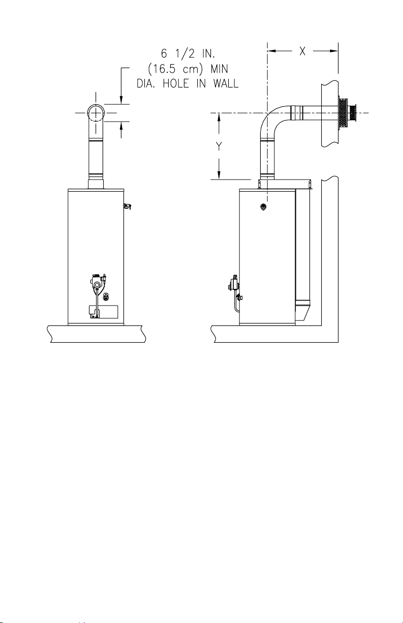
Figure 3
5
Page 6

VENT-AIR INTAKE SYSTEM INSTALLATION
WARNING
The vent-air intake system must be properly installed. Failure to
properly install the vent-air intake system could result in property
damage, personal injury or death.
Do not install any damaged vent-air intake system components.
Contact the manufacturer of the water heater for replacement parts.
IMPORTANT
When the following instructions specify, to seal a vent-air intake joint,
use only Loctite Ultra Blue 587 RTV Silicone sealant. A tube of Loctite
Ultra Blue 587 RTV Silicone sealant is supplied with each optional ventair intake kit. Make sure that all joints are completely sealed.
When drilling pilot holes for the #8 sheet metal screws through the six
(6) inch (15.2 cm) diameter components, be careful not to drill into the
inner four (4) inch (10.2 cm) diameter components.
WARNING
The vent-air intake terminal must be installed through an outside wall
in a horizontal position. This direct vent water heater is not designed
for through the roof vertical venting.
Tools Required For Vent-Air Intake Installation
The following minimum tools are required to properly install the ventair intake system. Note: Wall construction will determine tool usage.
• Tape Measure
• Drill
• 3/16 inch (4.5 mm) Diameter Drill Bit(s)
• 1/8 inch Diameter (3.0 mm) Drill Bit(s)
• Masonry Drill Bit(s) (For Poured Concrete, Concrete Block and
Brick Wall Construction)
• Reciprocating Saw w/appropriate Blade(s) (Dependent on Wall
Construction)
• Chisel (For Poured Concrete, Concrete Block and Brick Wall
Construction)
• Hammer (For Poured Concrete, Concrete Block and Brick Wall
Construction)
• 1/4 & 5/16 inch Nut Drivers (Preferred) or Slotted Head
Screwdriver
• Phillips Head Screwdriver
6
Page 7

1. Measure the vertical height “Y” required in your installation. (See Figure
3). Reference the appropriate Table A to determine number of vent-air
intake kits required in your installation.
2. Measure the horizontal length “X” required in your installation (See
Figure 3). Reference Table A to determine number of vent-air intake kits
required in your installation.
3. Cut a 6-1/2 inch (16.5 cm) diameter minimum clearance hole in the wall
at the point where the vent-air intake tubes will pass through the outside
wall and connect with the direct vent-air intake terminal
(See Figure 4).
4. From outside the building, position the outer wall mount plate and direct
vent-air intake terminal over the center of the opening. Mark the
mounting screw hole locations. With a 3/16 inch (4.5 mm) diameter drill
bit (not supplied), drill holes for the wall anchors (supplied). Install the
wall anchors but DO NOT affix the outer wall mount plate and direct
vent-air intake terminal to the wall at this time (See Figure 4). Note:
Certain construction of walls may require the use of a different type of
wall anchoring means than supplied. DO NOT modify the direct vent-air
intake terminal or outer wall mount plate.
Figure 4
7
Page 8

IMPORTANT
The following instructions detail the installation of the standard
horizontal vent-air intake kit.
5. Insert the straight end of the four (4) inch (10.2 cm) diameter elbow into
the flue reducer until firmly seated and oriented in the correct direction.
With a 1/8 inch (3.0 mm) diameter drill bit (not supplied), drill three (3)
holes, 120
o
apart, through the flue reducer into the four (4) inch (10.2
cm) diameter elbow. Fasten with three (3) #8 sheet metal screws
(supplied). Using the supplied special RTV silicone sealant, apply a
sufficient amount to seal the joint (See Figure 5).
Figure 5
6. Place the straight end of the six (6) inch (15.2 cm) diameter elbow over
the four (4) inch (10.2 cm) diameter elbow and plenum collar until seated
on top of the plenum box. Make certain that the six (6) inch (15.2 cm)
diameter elbow is oriented in the same direction as the four (4) inch
(10.2 cm) diameter elbow and both are oriented in the correct direction.
Drill three (3) 1/8 inch (3.0 mm) diameter holes, 120
o
apart, through the
six (6) inch (15.2 cm) diameter elbow into the plenum collar. Fasten with
three (3) #8 sheet metal screws (supplied) (See Figure 10).
8
Page 9

Figure 6
7. Extend the four (4) inch (10.2 cm) diameter telescopic tube to its
maximum length and slide the backing plate over it. Place the large end
of the four (4) inch (10.2 cm) diameter telescopic tube through the hole
in the outside wall. Insert the smaller end of the four (4) inch diameter
(10.2 cm) telescopic tube into the flared end of the four (4) inch (10.2
cm) diameter elbow, one (1) inch (2.5 cm) (or until seated). Drill three
(3) 1/8 inch (3.0 mm) diameter holes, 120
inch (10.2 cm) diameter elbow into the four (4) inch (10.2 cm) diameter
telescopic tube. Fasten with three (3) #8 sheet metal screws (supplied).
Adjust the overall length of the four (4) inch (10.2 cm) diameter
telescopic tube so that 2-1/2 inches (6.4 cm) extends beyond the outside
wall. Drill three (3) 1/8 inch (3.0 mm) diameter holes, 120
the four (4) inch (10.2) diameter telescopic tubes where the small and
large sections overlap. Fasten with three (3) #8 sheet metal screws
(supplied). Using the supplied special RTV silicone sealant, apply a
sufficient amount to seal the joints (See Figure 6).
o
apart, through the four (4)
o
apart, through
9
Page 10

Figure 7
8. Extend the six (6) inch (15.2 cm) diameter telescopic tube to its
maximum length. Place the large end of the six (6) inch (15.2 cm)
diameter telescopic tube over the collar on the outer wall mounting plate.
Drill three (3) 1/8 inch (3.2 mm) diameter holes, 120
six (6) inch (15.2 cm) diameter telescopic tube into the collar on the
outer wall mounting plate. Fasten with three
(supplied). Using the supplied special RTV silicone sealant, apply a
sufficient amount to seal the joint (See Figure 7).
(3) #8 sheet metal screws
o
apart, through the
Figure 8
10
Page 11

9. From outside the building, slide the six (6) inch (15.2 cm) diameter
telescopic tube through the opening in the wall until the outer wall
mounting plate is flush with the wall (See Figure 9).
Figure 9
10. Using the supplied special RTV silicone sealant, apply a bead one (1)
inch (2.5 cm) from the end of the four (4) inch (10.2 cm) diameter tube
that is part of the vent-air intake terminal. Slide the direct vent-air
intake terminal into the four (4) inch (10.2 cm) diameter telescopic tube
that extends through the wall and position it so it is flush with the outer
wall mounting plate. Make sure that the rain guard and the word “HOT”
on the end of the direct vent-air intake terminal are oriented properly.
Secure the direct vent-air intake terminal to the outer wall mounting
plate and wall with four (4) #10 x 1 inch screws (supplied) (See Figure
10). Note: Certain construction of walls may require the use of
different type of anchoring means than supplied. DO NOT modify the
direct vent-air intake terminal or outer wall mounting plate.
11
Page 12

Figure 10
11. From inside the building, slide the backing plate over the six (6) inch
(15.2 cm) diameter telescopic tube until it is flush with the wall. Adjust
the length of the six (6) inch (15.2 cm) diameter telescopic tube and
insert the end into the flared end of the six (6) inch (15.2 cm) diameter
elbow one (1) inch (2.5 cm) (or until seated). Drill three (3) 1/8 inch (3.0
mm) diameter holes, 120
o
apart, through the six (6) inch (15.2 cm)
diameter elbow into the six (6) inch (15.2 cm) diameter telescopic tube
and through the tubes where the small and large sections overlap.
Fasten with three (3) #8 sheet metal screws (supplied). Using the
supplied special RTV silicone sealant, apply a sufficient amount to seal
all joints (See Figure 11).
Figure 11
12
Page 13

12. Mark the mounting screw hole locations for the backing plate. Rotate
the backing plate in order to gain access to the markings. With a 3/16
(4. 5 mm) inch diameter drill bit (not supplied), drill holes for the
supplied wall anchors. Install the wall anchors and secure the backing
plate to the wall with four (4) #10 x 1 inch screws (supplied) (See Figure
12). Note: Certain construction of walls may require the use of a
different type of anchoring means than supplied.
Figure 12
IMPORTANT
When the installation is complete, visually inspect the air intake
system to insure that all joints are completely sealed.
13
Page 14

VENT-AIR INTAKE KITS
14
Page 15

DIRECT VENT WATER HEATER VENTING PARTS LISTS
PART NAME & DESCRIPTION
1. Direct Vent-Air Intake Terminal 6. Inner Telescopic Vent Tube
2. Outer Wall Mounting Plate 7. Inner Elbow
3. Inner Wall Backing Plate 8. Vent Terminal Guard (Optional
not included)
4. Outer Telescopic Air Intake Tube 9. Special RTV silicone sealant
5. Outer Elbow
15
Page 16

NOTES
16
 Loading...