

Bradford White Copper Brute II 720-B, Copper Brute II, BWCV0500, BWCV0750, BWCV1000 Specification Sheet
...Page 1
Pump-Mounted Water Heaters
BWCV - Copper Brute II
Indoor/Outdoor Sizes 500,000 - 1,999,000 BTU/Hr.
84% Thermal Efficiency
The unit will be designed and constructed in accordance with the ASME Boiler and Pressure Vessel Code Section IV requirements for 160 psi working pressure.
The units will bear the ASME "H" stamp and be registered by the National Board.
720-B 0811
MANUFACTURED UNDER ONE OR MORE OF THE FOLLOWING U.S. PATENTS: 5,954,492; 5,761,379; 5,943,984; 5,081,696; 5,988,117; 6,142,216; 5,199,385; 5,574,822; 5,372,185; 5,485,879; 5,277,171;
(B1)5,341,770; 5,660,165; 5,596,952; 5,682,666; 4,904,428; 5,023,031; 5,000,893; 4,669,448; 4,829,983; 4,808,356; 5,115,767; 5,092,519; 5,052,346; 4,416,222; 4,628,184; 4,861,968; 4,672,919; Re. 34,534;
7,270,087 B2. OTHER U.S. AND FOREIGN PATENT APPLICATIONS PENDING. CURRENT CANADIAN PATENTS: 1,272,914; 1,280,043; 1,289,832; 2,045,862; 2,112,515; 2,108,186; 2,107,012; 2,092,105; 2,409,271.
©2011, Bradford White Corporation. All rights reserved. Printed in U.S.A.
5-Year Limited Heat Exchanger Warranty / 1-Year Limited Warranty on Component Parts.
For more information on warranty, please visit www.bradfordwhite.com
For products installed in USA, Canada and Puerto Rico. Some states do not allow limitations on warranties.
See complete copy of the warranty included with the heater.
Page 2
W*
W*
G
V*
A
V*
W*
B
C
H
E
V*
B
C
D
W*
F
V*
193/
4
411/
2
351/
3
133/
4
183/
4
122/
5
133/
4
2
7
3
/
4
291/
3
10
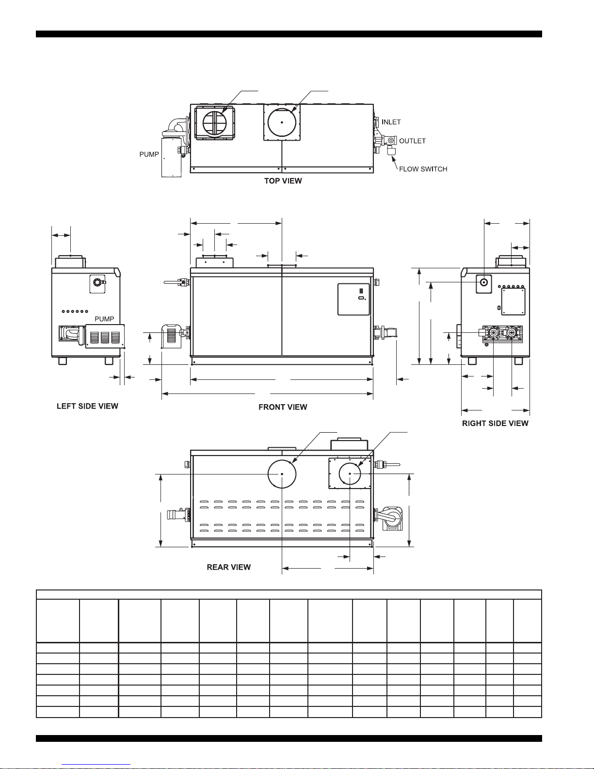
Copper-Brute II (500-2000)
Water Heater Dimensions
Dimensions are shown in inches.
DIMENSIONS
50ft.
50ft.
50ft.
50ft.
50ft.
50ft.
50ft.
BWCV0500
BWCV0750
BWCV1000
BWCV1250
BWCV1500
BWCV1750
BWCV2000
33
1
/
2
45
1
/
2
57
1
/
2
68
78
1
/
2
89
99
1
/
2
85
116
146
172
199
226
253
15
3
/
4
21
3
/
4
28
3
/
4
34
39
3
/
4
44
1
/
2
49
3
/
4
40
55
73
86
101
113
126
5
3
/
4
5
3
/
4
5
3
/
4
10
1
/
8
10
1
/
8
10
1
/
8
10
1
/
8
15
15
15
26
26
26
26
29
3
/
4
29
3
/
4
29
3
/
4
30
3
/
4
30
3
/
4
30
3
/
4
30
3
/
4
76
76
76
78
78
78
78
32
3
/
4
32
3
/
4
32
3
/
4
29
1
/
2
29
1
/
2
29
1
/
2
29
1
/
2
83
83
83
75
75
75
75
7
3
/
4
7
3
/
4
7
3
/
4
8
3
/
4
8
3
/
4
8
3
/
4
8
3
/
4
20
20
20
28
28
28
28
8
3
/
4
8
3
/
4
7
8
3
/
4
8
3
/
4
8
3
/
4
8
3
/
4
22
22
18
22
22
22
22
46
58
70
80
91
101
112
117
147
178
203
231
256
284
6
6
8
8
8
8
12
15
15
20
20
20
20
20
8
10
10
12
12
14
14
20
25
25
30
30
36
36
6
8
8
8
8
8
12
15
20
20
20
20
20
30
3
3
3
3
3
3
3
A
LengthModel
Numbers
B
Ct. Line
Vent Connect
to Side
C
Ct. Line
Air Connect
to Side
D
Ct. Line
Air
Connect
to Floor
E
Ct. Line
Vent
Connect
to Floor
F
Ct. Line
Air Connect
to Back
of Unit
G
Ct. Line
Vent Connect
to Back
of Unit
H
Length
Plus
Pump
W*
Air
Connect
V*
Vent
Connect
Horiz.
Vent
Pipe
Max.
Pipe
Length
No.
of
Elbows
inch cm inch cm inch cm inch cm inch cm inch cm inch cm inch cm inch cm inch cm inch cm
* Air and vent connections may be on top or back of unit and are field convertible.
Page 3

Gas2Water2Shipping
Model Input
1
Output
1
90°F 50°C 100°F 56°C 140°F 78°C
Conn. Conn. Weight
Numbers BTU/Hr. BTU/Hr. GPH LPH GPH LPH GPH LPH inches inches (lbs.) (kg)
BWCV0500 500,000 425,000 567 2143 510 1929 364 1378 11⁄4 2 480 218
BWCV0750 750,000 638,000 850 3214 765 2893 547 2066 11⁄4 2 560 254
BWCV1000 999,000 849,000 1133 4281 1019 3853 728 2752 11⁄2 21⁄2 670 304
BWCV1250 1,250,000 1,063,000 1417 5357 1276 4821 911 3444 2 21⁄2 730 331
BWCV1500 1,500,000 1,275,000 1701 6429 1531 5786 1093 4133 2 21⁄2 815 370
BWCV1750 1,750,000 1,488,000 1984 7500 1786 6750 1276 4821 2 21⁄2 880 400
BWCV2000 1,999,000 1,699,000 2266 8567 2040 7710 1457 5507 2 2
1
⁄2 1010 459
Copper-Brute II Models
1. Input and output must be derated 4% per 1000 feet above sea level when installed above 2000 feet altitude.
2. Dimensions are nominal.
Note: GPH = gallons per hour, LPH = liters per hour.
WATER TEMPERATURE RISE IN DEGREES
Note: GPM= gallons per minute, LPM=liters per minute
Water Flow Data
Model Flow Flow Flow Flow Flow Flow
Numbers GPM LPM GPM LPM GPM LPM
BWCV0500 90 341 68 257 45 170
BWCV0750 90 341 68 257 45 170
BWCV1000 90 341 68 257 45 170
BWCV1250 90 341 68 257 68 257
BWCV1500 90 341 68 257 68 257
BWCV1750 90 341 68 257 68 257
BWCV2000 112 424 112 424 112 424
HARD WATER NORMAL WATER SOFT WATER
5678 9 10 11 12 13 14 15 16123
BWC4VA 2
SERIES USAGE FUEL ALTITUDE LOCATION REVISION HEAT
EXCHANGER
FIRING
MODE
OPTIONS
CODE
PUMP
OPTIONS
B (std.)
K
P
S
K=Two-Stage
N=Three-Stage
L=Four-Stage
X (std.)
J
L
N (std.)
S
H
SIZE
VN
P
A
C=Convertible
0
0
1
1
1
1
2
5
7
0
2
5
7
0
0
5
0
5
0
5
0
0
0
0
0
0
0
0
Copper-Brute II (500-2000)
Water Heater Specifications
(1-3) Model Series Designation
B W C = Copper Brute II
(4) Usage
V = Volume Water
(5-8) Size
0 5 0 0 = 500,000 BTU/Hr. input
0 7 5 0 = 750,000 BTU/Hr. input
1 0 0 0 = 999,000 BTU/Hr. input
1 2 5 0 = 1,250,000 BTU/Hr. input
1 5 0 0 = 1,500,000 BTU/Hr. input
1 7 5 0 = 1,750,000 BTU/Hr. input
2 0 0 0 = 1,999,000 BTU/Hr. input
(9) Fuel
N = Natural Gas
P = Propane
(10) Altitude
A = 0-10,000 feet
(11) Location
C=Convertible
(12) Firing Mode
K = Two-stage (500 & 750)
N = Three-stage (1000)
L = Four-stage
(1250, 1500, 1750 & 2000)
(13) Revision
2 = First Revision of Design
(14) Heat Exchanger
B = Glass-lined cast iron headers /
copper tubes/ bronze trim
K = Bronze headers / copper tubes/
bronze trim
P = Glass-lined cast iron headers /
cu-nickel / bronze trim
S = Bronze headers / cu-nickel /
bronze trim
(15) Option Code
X = Standard
J = CSD-1, FM, IRI, IL
L = LDS (consult factory)
(16) Pump Options
N = Pump mounted water heater,
normal water pump
S = Pump mounted water heater,
soft water pump
H = Pump mounted water heater,
hard water pump
Model Character Designation
Model Numbers Firing Stage
BWCV0500 2-Stage
BWCV0750 2-Stage
BWCV1000 3-Stage
BWCV1250 4-Stage
BWCV1500 4-Stage
BWCV1750 4-Stage
BWCV2000 4-Stage
Firing Rates
5
Page 4

720-B-0811 Printed in U.S.A.
■ Thermal efficiency up to 84%
■ ASME 160 psi working pressure heat
exchanger
■ ASME "H" stamp, designed and certified
for potable water use
■ Flanged bronze water connections
■ Glass-lined headers
■ External header gaskets
■ 125 psi (861 kPa) ASME rated pressure
relief valve
■ Flow switch, mounted and wired
■ Temperature/pressure gauge
■ Pump, mounted and wired
■ Multiple operating gas valve/pressure
regulators
■ Manual “A” gas valve
■ Washable intake air filter
■ Multiple, removable burner trays
■ Stainless steel burners
■ Built-in draft fan for Category I or III vent
systems
■ Air pressure switch
■ Burner site glass
■ 24V control system
■ 115/24VAC transformer
■ Ignitor access panels
■ Energy Management Monitor (EM
2
)
pump time delay
■ Manual reset high limit
■ Automatic reset high limit
■ Electronic PID staging control with LCD
and touchpad
■ PC board for electrical connections
■ External controller connections with
selector switch
■ Hot surface ignition
■ On/Off toggle switch
■ Pump time delay
■ Diagnostic lights
■ Less than 10 ppm NOx
■ All models can be converted to either
indoor use or outdoor use. For outdoor
use, you must order exhaust vent and air
intake vent (consult factory for part
numbers)
Standard Features
Optional Equipment
■ Copper-nickel heat exchanger
■ Normally open vent valve
(see IRI Package)
■ Low water cutoff
■ Motorized gas safety valve
(see LDS Package)
■ Double stack stand
■ Reverse Heat Exchanger - switches the
inlet and outlet to left side and pump to
the right side
■ Indoor Venting Accessories (required for
sidewall venting)
■ CSD-1 Package includes:
Single Try Ignition, High and Low Gas
Pressure Switches, and Gas Regulator.
Excludes Low Water Cutoff.
■ IRI Package, added to the CSD-1 package
includes:
Single Try Ignition, High and Low Gas
Pressure Switches with Manual reset,
Normally Open Vent Valve, Safety Valve
with Gas Regulator and Leak Test Valve.
Excludes Low Water Cutoff
■ LDS Package includes:
Size 500-1000:
Safety Valve with Gas Regulator, High Gas
Pressure Switch and Leak Test Valve.
Size 1250-2000:
Solenoid Safety Valve, Motorized Valve
with Proof of Closure, Leak Test Valve,
High and Low Gas Pressure Switches.
Clearances
*When vent and/or air is connected to the back, 36" (91cm) is suggested.
inch cm inch cm
Left Side 1 2.5 24 61
Right Side 1 2.5 24 61
Top 1 2.5 12 30
Back* 1 2.5 12 30
Front 1 2.5 36 91
Vent
APPLIANCE
SURFACE
REQUIRED CLEARANCE FROM
COMBUSTIBLE MATERIAL
SUGGESTED SERVICE
ACCESS CLEARANCES
Per venting supplier’s instructions
Power (HP) Current (Amps)
Model Numbers Soft Normal Hard Soft Normal Hard
BWCV0500
1
⁄3
1
⁄3
3
⁄4 2.8 2.8 7.2
BWCV0750
1
⁄3
1
⁄3
3
⁄4 2.8 2.8 7.2
BWCV1000
1
⁄3
1
⁄2
3
⁄4 2.8 5.2 7.2
BWCV1250
1
⁄3
1
⁄2
3
⁄4 2.8 5.2 7.2
BWCV1500
1
⁄3
3
⁄4
3
⁄4 2.8 7.2 7.2
BWCV1750
3
⁄4
3
⁄4
3
⁄4 7.2 7.2 7.2
BWCV2000 1 1 1 9.8 9.8 9.8
Motor Electrical Data
WATER CATEGORY
©2011, Bradford White Corporation. All rights reserved.
Ambler, PA
For U.S. and Canada field service, contact your professional installer or local Bradford White sales representative.
Sales 800-523-2931 ●Fax 215-641-1670 / Technical Support 800-334-3393 ●Fax 269-795-1089 ●Warranty 800-531-2111 ●Fax 269-795-1089
International: Telephone 215-641-9400
●
Telefax 215-641-9750 / www.bradfordwhite.com
Sales / Technical Support 866-690-0961 / 905-238-0100 ●Fax 905-238-0105 / www.bradfordwhite.com
 Loading...