

Page 1
MANUFACTURED UNDER ONE OR MORE OF THE FOLLOWING U.S. PATENTS: 5,954,492; 5,761,379; 5,943,984; 5,081,696; 5,988,117; 6,142,216; 5,199,385; 5,574,822; 5,372,185; 5,485,879; 5,277,171;
(B1)5,341,770; 5,660,165; 5,596,952; 5,682,666; 4,904,428; 5,023,031; 5,000,893; 4,669,448; 4,829,983; 4,808,356; 5,115,767; 5,092,519; 5,052,346; 4,416,222; 4,628,184; 4,861,968; 4,672,919; Re. 34,534;
7,270,087 B2. OTHER U.S. AND FOREIGN PATENT APPLICATIONS PENDING. CURRENT CANADIAN PATENTS: 1,272,914; 1,280,043; 1,289,832; 2,045,862; 2,112,515; 2,108,186; 2,107,012; 2,092,105; 2,409,271.
10-Year Limited Heat Exchanger Warranty / 1-Year Limited Warranty on Component Parts.
For more information on warranty, please visit www.bradfordwhite.com
For products installed in USA, Canada and Puerto Rico. Some states do not allow limitations on warranties.
See complete copy of the warranty included with the heater.
734-B 0913
Brute Deluxe Volume Water Heater
Indoor or Outdoor 500,000 - 1,999,000 BTU/Hr.
84.2% Thermal Efficiency
Page 2
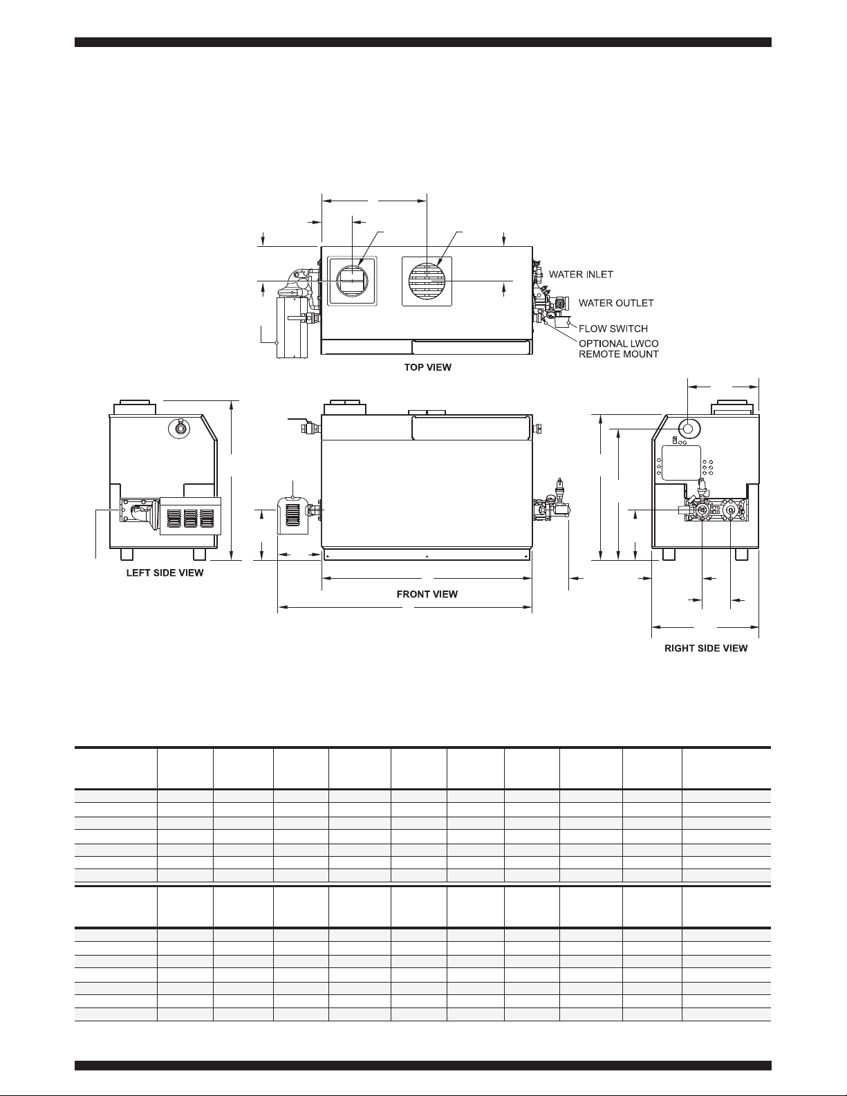
Dimensions shown in inches mm
AIR INLET
CONN.
VENT
CONN.
E
D
C
B
G
A
F
43
1105
/
1
2
19
495
/
1
2
7
197
/
3
4
39
1011
/
13
16
13
348
/
11
16
13
348
/
11
16
13
353
/
15
16
12
312
/
5
16
10
254
36
914
PUMP
PUMP
PUMP
Brute Deluxe Volume Water Heater Specifications
Connections
NPT Size
A
Depth
in.
Model
Number
Water
in.
Gas
in.
C
in.
163/
4
223/
4
283/
4
34
39
1
/
2
443/
4
493/
4
D
in.
61/
2
61/
2
61/
2
101/
4
101/
4
101/
4
101/
4
E
in.
10
10
10
10
10
10
10
F
in.
8
9
1
/
2
91/
2
9
9
9
9
Air
Inlet
Conn.
in.
6
6
8
8
8
8
12
Vent
Conn.
in.
8
10
10
12
12
14
14
2 NPT
2 NPT
2
1
/2 NPT
2
1
/2 NPT
2
1
/2 NPT
2
1
/2 NPT
2
1
/2 NPT
1
1
/4 NPT
1
1
/4 NPT
1
1
/2 NPT
2 NPT
2 NPT
2 NPT
2 NPT
B
Width
in.
333/
4
453/
4
573/
4
681/
4
783/
4
891/
4
993/
4
297/
16
297/
16
297/
16
297/
16
297/
16
297/
16
297/
16
BMT2V0500
BMT2V0750
BMT2V1000
BMT2V1250
BMT2V1500
BMT2V1750
BMT2V2000
Connections
NPT Size
A
Depth
mm.
Model
Number
Water
mm.
Gas
mm.
C
mm.
425
578
730
864
1003
1137
1264
D
mm.
165
165
165
260
260
260
260
E
mm.
254
254
254
254
254
254
254
F
mm.
203
241
241
229
229
229
229
G
in.
461/
4
581/
4
701/
4
803/
4
911/
4
1013/
4
1121/
4
G
mm.
1175
1480
1784
2051
2318
2584
2851
Air
Inlet
Conn.
mm.
152
152
203
203
203
203
305
Vent
Conn.
mm.
203
254
254
305
305
356
356
50 NPT
50 NPT
64 NPT
64 NPT
64 NPT
64 NPT
64 NPT
32 NPT
32 NPT
38 NPT
50 NPT
50 NPT
50 NPT
50 NPT
B
Width
mm.
857
1162
1467
1734
2000
2267
2534
747
747
747
747
747
747
747
BMT2V0500
BMT2V0750
BMT2V1000
BMT2V1250
BMT2V1500
BMT2V1750
BMT2V2000
Dimensions
Page 3

(1-4) Model Series Designation
BMT2 = Brute Deluxe
(5) Usage
V= Volume Water Heater
(6-9) Size
0500 = 500,000 BTU/Hr. input
0750 = 750,000 BTU/Hr. input
1000 = 999,000 BTU/Hr. input
1250 = 1,250,000 BTU/Hr. input
1500 = 1,500,000 BTU/Hr. input
1750 = 1,750,000 BTU/Hr. input
2000 = 1,999,000 BTU/Hr. input
Model Character Designation
Brute Deluxe Volume Water Heater Specifications
BoilerModels
Volts
120
Phase
Single
Amps
15
20
20
Pump Circuit Size Blower
Circuit
Volts
120
Phase
Single
Amps
15
15
20
Included in
Boiler
Circuit
0500-0750
1000 - 1750
2000
Electrical Data
Water Flow Data
Hard
Water
Normal
Water
Soft
Water
Model
Number
BMT2V0500
BMT2V0750
BMT2V1000
BMT2V1250
BMT2V1500
BMT2V1750
BMT2V2000
90
90
90
90
90
90
120
Flow
GPM
341
341
341
341
341
341
424
Flow
LPS
68
68
68
68
68
68
112
Flow
GPM
257
257
257
257
257
257
424
Flow
LPS
45
45
45
68
68
68
112
Flow
GPM
170
170
170
257
257
257
424
Flow
LPS
Shipping
Weight
Input
1
Model
Number
BMT2V0500
BMT2V0750
BMT2V1000
BMT2V1250
BMT2V1500
BMT2V1750
BMT2V2000
lbs.BTU/Hr. kg.
500,000
750,000
999,000
1,250,000
1,500,000
1,750,000
1,999,000
kW
146.5
219.8
292.7
366.3
439.6
512.8
585.8
124.6
186.9
248.8
311.4
373.6
435.9
497.9
Output
1
BTU/Hr.
425,000
638,000
849,000
1,062,500
1,275,000
1,487,500
1,699,000
kW
480
560
670
730
815
880
1010
218
254
304
331
370
400
459
Sizing Data
NOTES:
1. Input and output must be derated 4% per 1000 feet
above sea level when installed above 2000 feet altitude.
in.
Required Clearance from
Combustible Material
Suggested Service
Access Clearance
Appliance
Surface
1
1
1
1
1
mm.
25
25
25
25
25
in.
24
24
12
12
36
mm.
607
607
305
305
914
Left Side
Right Side
Top
Back
Front
Vent
Per venting system
supplier's instructions
Clearances
6789 10 131234
BMT
2
5
V
SERIES USAGE FUEL FIRING
MODE
K
SIZE
0500
0750
1000
1250
1500
1750
2000
V N
P
11
ALTITUDE
A
12
LOCATION
16
PUMP
OPTIONS
15
OPTIONS
CODE
14
HEAT
EXCHANGER
C
B
P
2
5
X
J
N
H
S
(10) Fuel
N = Natural Gas
P = Propane
(11) Altitude
A = 0-10,000 ft.
(12) Location
C = Indoor or Outdoor
(13) Firing Mode
K = 2-Stage
(14) Heat Exchanger
B = Glass Lined Cast Iron with
Copper Tubes Bronze Trim
(Standard)
P = Glass Lined Cast Iron with
Copper Tubes Bronze trim
with HLW Stamp
2 = Glass Lined Cast Iron with
Cupronickel Tubes Bronze
Trim
5 = Glass Lined Cast Iron with
Cupronickel Tubes Bronze
trim with HLW Stamp
(15) Options
X = Standard
J = CSD-1, FM
(16) Options
N = Normal
H = Pump Mounted (Hard
Water Conditions)
S = Pump Mounted (Soft
Water Conditions)
Note: Soft water: 1 to 7.5 grains per gallon.
Normal water: 7.6 to 17 grains per gallon. Hard
water: More than 17 grains per gallon.
Recovery Data
GPH Recovery at Degree Rise
40°F
Model
Number
BMT2V0500
BMT2V0750
BMT2V1000
BMT2V1250
BMT2V1500
BMT2V1750
BMT2V2000
1276
1915
2548
3189
3827
4464
5099
50°F
1020
1532
2038
2551
3061
3571
4079
60°F
850
1277
1699
2126
2551
2976
3399
70°F
729
1094
1456
1822
2187
2551
2914
80°F
638
957
1274
1594
1913
2232
2550
90°F
567
851
1132
1417
1701
1984
2266
100°F
510
766
1019
1276
1531
1786
2040
120°F
425
638
849
1063
1276
1488
1700
140°F
364
547
728
911
1093
1276
1457
LPH Recovery at Degree Rise
22°C
Model
Number
BMT2V0500
BMT2V0750
BMT2V1000
BMT2V1250
BMT2V1500
BMT2V1750
BMT2V2000
4,821
7,238
9,632
12,054
14,464
16,875
19,274
28°C
3,857
5,790
7,705
9,643
11,571
13,500
15,419
33°C
3,214
4,825
6,421
8,036
9,643
11,250
12,850
39°C
2,755
4,136
5,504
6,888
8,265
9,643
11,014
44°C
2,411
3,619
4,816
6,027
7,232
8,438
9,637
50°C
2,143
3,217
4,281
5,357
6,429
7,500
8,566
56°C
1,929
2,895
3,853
4,821
5,786
6,750
7,710
67°C
1,607
2,413
3,211
4,018
4,821
5,625
6,425
78°C
1,378
2,068
2,752
3,444
4,133
4,821
5,507
Page 4

Printed in U.S.A.
734-B-0913
©2013, Bradford White Corporation. All rights reserved.
Ambler, PA
For U.S. and Canada field service, contact your professional installer or local Bradford White sales representative.
Sales 800-523-2931 ●Fax 215-641-1670 / Technical Support 800-334-3393 ●Fax 269-795-1089 ●Warranty 800-531-2111 ●Fax 269-795-1089
International: Telephone 215-641-9400
●
Telefax 215-641-9750 / www.bradfordwhite.com
Sales / Technical Support 866-690-0961 / 905-238-0100 ●Fax 905-238-0105 / www.bradfordwhite.com
Brute Deluxe Volume Water Heater Specifications
■ ASME 160 psi working pressure heat
exchanger
■ ASME “H” stamp
■ Two-stage firing
■ Flanged water connections
■ Glass-lined headers
■ External header gaskets
■ 75 psi (517 kPa) ASME rated pressure
relief valve
■ Flow switch
■ Temperature pressure gauge
■ Pump, mounted and wired
■ Multiple operating gas valve/ pressure
regulators
■ Manual “A” gas valve
■ Intake air filter
■ Multiple, removable burner trays
■ Stainless steel burners
■ Built-in draft fan for Category I or III vent
systems
■ Air pressure switch
■ Burner site glass
■ 24V control system
■ 115/24VAC transformer
■ Manual reset high limit
■ External controller connections with
selector switch
■ Hot surface ignition
■ On/Off toggle switch
■ Pump time delay
■ Less than 10 ppm NOx
Standard Features
Factory Mounted Options
■ CSD-1, FM, Gap, IL controls (does not include low water cutoff)
■ Glass lined cast iron headers, copper tubes, with bronze trim
■ Glass lined cast iron headers, cupronickel tubes with iron trim
■ Glass lined cast iron headers, cupronickel tubes with bronze trim
■ Reversed heat exchanger and pump
■ Low water cutoff
■ Auto reset high limit
Field Installed Accessories
■ Alarm package (with bell)
■ Side-wall vent terminal for indoor unit with horizontal venting
■ Side-wall combustion air terminal for indoor unit with horizontal ducted air
■ Air terminal for outdoor unit
■ Vent terminal for outdoor unit
Sample Specification
The boiler shall be a Bradford White Model BMT2V _______________ , rated at the input and output shown on the schedule. The unit(s) shall be design certified
to comply with the current edition of the Harmonized ANSI Z21.10.3 / CSA 4.3 Standard for Gas Water Heaters, and shall be design certified for both indoor
and outdoor use. The unit(s) shall be designed and constructed in accordance with the ASME Boiler & Pressure Vessel Code, Section IV requirements for 160
psi (1103 kPa) working pressure, and shall bear the ASME “H” Stamp. The unit(s) shall be constructed to comply with the efficiency requirements of the latest
edition of ASHRAE Standard 90.1.
The water tube heat exchanger shall be a straight tube design with ten 7/8" (22mm) inner diameter integral finned copper tubes. The tubes shall be rolled
directly into glass-lined cast iron headers, rated at 160 psi (1103 kPa) working pressure. The heat exchanger shall be a low water volume design. All gaskets
shall be non-metallic, outside the jacket, and separated from the combustion chamber by at least 3.5" (89mm) to eliminate deterioration from heat. Headers
shall have covers permitting visual inspection and cleaning of all internal surfaces. The heat exchanger shall have a ten year warranty.
The piping side header shall have removable flanges, and the water heater design shall permit removal of the complete heat exchanger for service from either
the front or top, to facilitate maintenance.
Each unit shall have a pump time delay. The pump time delay shall be adjustable from 0.1 to 10 minutes for continued pump circulation after the call for heat
has been satisfied, to remove residual heat from the unit’s combustion chamber.
The units shall use a proved heat surface ignition with a 15 second pre-purge cycle to clean out the combustion chamber. Upon the call for heat, if a flame is
not detected, the ignition module shall attempt 2 more time before locking out, and required manual reset. If there is a loss of flame signal during a call for
heat, the ignition control shall attempt three re-ignition cycles before locking out. (Units with some options such as ASME CSD-1, are built with single-try
ignition controls.) The control circuit shall be 24V. Unit shall be 120V, single-phase.
Burners shall be multi-port design, and shall be constructed of high temperature stainless steel. The burners shall be designed to mix air and gas, and burn
cleanly with NOx emissions not exceeding 10ppm. Burners shall be in easily-removable burner tray assemblies with no more than 4 burners per tray.
Dimensions and specifications subject to change without notice in accordance with our policy of continuous product improvement.
 Loading...