

Bradford White BMGV3500, BMGH4000, BMGH2500, BMGV4000, BMGH2000 Installation And Operation Instructions Manual
...Page 1
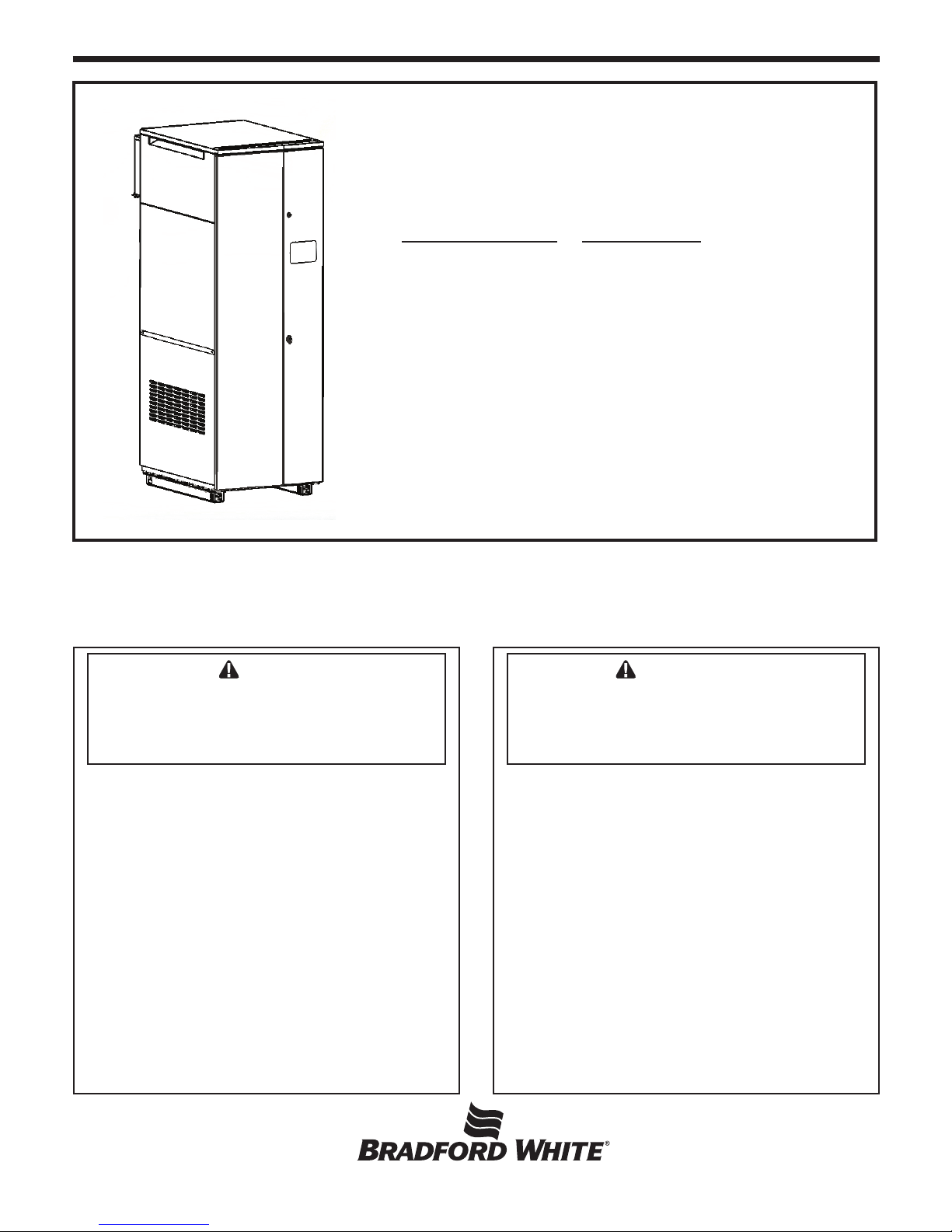
Installation and Operation Instructions Document 1293E
Installation and
MagnaTech
Operation Instructions for
Brute MagnaTech
®
Modulating Boiler Water Heater
Model BMGH1600 Model BMGV1600
1,600 MBTU/h 1,600 MBTU/h
Model BMGH2000 Model BMGV2000
1,999 MBTU/h 1,999 MBTU/h
Model BMGH2500 Model BMGV2500
2,499 MBTU/h 2,499 MBTU/h
Model BMGH3000 Model BMGV3000
3,000 MBTU/h 3,000 MBTU/h
Model BMGH3500 Model BMGV3500
3,500 MBTU/h 3,500 MBTU/h
Model BMGH4000 Model BMGV4000
4,000 MBTU/h 4,000 MBTU/h
FOR YOUR SAFETY: This product must be installed and serviced by a professional service technician,
qualied in hot water boiler and heater installation and maintenance. Improper installation and/or operation
could create carbon monoxide gas in ue gases which could cause serious injury, property damage, or
death. Improper installation and/or operation will void the warranty.
WARNING
If the information in these instructions is
not followed exactly, a re or explosion
may result causing property damage,
personal injury or death.
Do not store or use gasoline or other
ammable vapors and liquids in the vicinity
of this or any other appliance.
WHAT TO DO IF YOU SMELL GAS
• Do not try to light any appliance.
• Do not touch any electrical switch; do not
use any phone in your building.
• Immediately call your gas supplier from
a neighbor’s phone. Follow the gas
supplier’s instructions.
• If you cannot reach your gas supplier, call
the re department.
Installation and service must be performed
by a qualied installer, service agency, or gas
supplier.
AVERTISSEMENT
Assurez-vous de bien suivres les instructions
données dans cette notice pour réduire au
minimum le risque d’incendie ou d’explosion ou
pour éviter tout dommage matériel, toute blessure
ou la mort.
Ne pas entreposer ni utiliser d’essence ou ni
d’autres vapeurs ou liquides inammables dans
le à proximité de cet appareil ou de tout autre
appareil.
QUE FAIRE SI VOUS SENTEZ UNE ODEUR DE GAZ:
• Ne pas tenter d’allumer d’appareils.
• Ne touchez à aucun interrupteur. Ne pas vous servir
des téléphones dans le bâtiment où vous vous trovez.
• Appelez immédiatement votre fournisseur de
gaz depuis un voisin. Suivez les instructions du
fournisseur.
• Si vous ne pouvez rejoindre le fournisseur de
gaz, appelez le sservice des incendies.
L’installation et l’entretien doivent être assurés par
un installateur ou un service d’entretien qualié ou
par le fournisseur de gaz.
H2359201E
Page 2

Table of Contents
B
RADFORD WHITE
Section 1 - GENERAL INFORMATION
1.1 Introduction ...................................................... 1
1.2 Safety Notes .....................................................1
1.3 ModelNomenclature/Identication ...............2
1.4 Warranty ........................................................... 2
1.5 Unit Overviews ( all sizes ) ...........................3-5
1.6 Dimensions ....................................................... 6
1.7 Unpacking ........................................................7
Section 2 - LOCATING THE APPLIANCE
2.1 Locating the Appliance .....................................7
2.2 Correct Vent Distance
from Outside Wall or Roof Termination ...........7
Section 3 - VENTING AND COMBUSTION AIR
3.1 Combustion Air ................................................ 8
3.1.1 Combustion Air From Room ............................8
3.1.2 Ducted Combustion Air ....................................9
3.2 Venting .............................................................9
3.2.1 Common Venting ............................................10
3.2.3 Venting Requirements Unique to Canada ......10
3.3 Locating the Vent and Combustion Air
Terminals ........................................................ 11
3.3.1 Side Wall Vent Terminal ................................. 11
3.3.2 Side Wall Combustion Air Terminal .............. 13
3.3.3 Vertical Vent Terminal .................................... 14
3.3.4 Vertical Combustion Air Terminal.................. 14
3.3.5 Installations in the Commonwealth of
Massachusetts ................................................. 14
3.4 Common Vent Test .........................................15
3.5 Outdoor Installation ........................................16
Section 6 – WATER CONNECTIONS, BMGH
6.1 BMGH System Piping: Hot Supply
Connections .................................................... 19
6.2 BMGH Cold Water Make-Up ........................ 19
6.3 BMGH Freeze Protection ............................... 19
6.4 BMGH Suggested Piping Schematics .......20-24
6.5 Condensate Drain Trap ...............................20
Section 7 - WATER CONNECTIONS, MGV
7.1 BMGV Water Quality ..................................... 25
7.2 BMGV Suggested Piping Schematics ............ 25
7.3 BMGV Piping Requirements .........................25
7.4 BMGV Cold Water Make-Up......................... 26
7.5 BMGV Freeze Protection ............................... 26
7.6 BMGV Water Flow ........................................ 27
7.7 Condensate Drain Trap ................................... 27
Section 8 – ELECTRICAL CONNECTIONS
8.1 Installation Warnings .....................................28
8.2 Main Power Connections ...............................28
8.3 Pump Connections and Operation .................. 29
8.4 Control Panel Layout......................................30
8.5 Wiring Diagrams .......................................32-35
8.6 High Voltage Wiring Diagrams .................36-40
8.7 Ladder Diagrams ......................................41-45
Section 4 - GAS SUPPLY AND PIPING
4.0 Gas Supply and Piping ................................... 16
Section 5 - WATER FLOW REQUIREMENTS
5.1 MagnaTech Boiler Flow and Head
Requirements .................................................. 18
5.2 MagnaTech Water Heater Flow and Head
Requirements .................................................. 18
i
Page 3

MagnaTech
BOILERS AND VOLUME WATER HEATERS
Section 9 – NAVIGATING THE TOUCH SCREEN
9.1 The Touch Screen .......................................... 46
9.2 Using the Touch Screen .................................. 46
9.3 VericationProcessforSafety-Related
Parameters ...................................................... 48
9.4 While Operating - Checking Individual
Parameters ...................................................... 49
9.5 ConguringParametersonIndividual
Controllers ...................................................... 50
9.6 Setting the Date and Time on the
System Display......................51
9.7 CongurationMenus(ALL) ..........................52
9.7.1 SystemIdentication&Access ...................... 52
9.7.2 CH-CentralHeatConguration....................53
9.7.3 OutdoorResetConguration .........................53
9.7.4 DHW-DomesticHotWaterConguration ...53
9.7.5 WarmWeatherShutdownConguration ........53
9.7.6 DemandPriorityConguration ......................53
9.7.7 ModulationConguration ..............................53
9.7.8 PumpConguration .......................................53
9.7.9 StatisticsConguration ..................................54
9.7.10 High Limits ....................................................54
9.7.11 Stack Limits ....................................................54
9.7.12 Delta T Limits.................................................54
9.7.13 FrostProtectionConguration ....................... 54
9.7.14 Burner Control Ignition .................................. 56
9.7.15 SystemConguration ..................................... 56
9.7.16 SensorConguration ...................................... 56
9.7.17 LeadLagSlaveConguration ........................56
9.7.18 LeadLagMasterConguration .....................59
9.8 Parameter Defaults and Ranges ......................59
9.9 Connections to a
Building Automation System ......................... 63
9.10 Variable Speed Pump Control (VSPC) ........... 64
9.11 Combustion Setup Procedure ......................... 65
Section 10 - INITIAL STARTUP INSTRUCTIONS
10.1 Filling the Boiler System ................................68
10.2 Initial Operation .............................................69
10.2.1 Initial Burner Operation ................................. 69
10.2.2 Combustion Setup Procedure ......................... 69
10.3 Shutting Down the MagnaTech ...................... 69
10.4 Restarting the MagnaTech .............................. 69
Section 11 – MAINTENANCE
11.1 System Maintenance.......................................70
11.2 Maintenance Notes ......................................... 70
11.2.1 Burner ............................................................. 70
11.2.2 Modulating Gas Valve/ Venturi ...................... 70
11.2.3 Controller ....................................................... 71
11.2.4 Hot Surface Ignitor ......................................... 71
11.2.5 Flame Sensor .................................................. 71
11.2.6 Blower ............................................................ 71
11.2.7 Heat Exchanger Tubes .................................... 72
11.2.8 Gas Pressure Switches .................................... 72
Section 12 – TROUBLESHOOTING
12.1 About Lockouts, Holds, and Alerts ................73
12.1.1 Responding to a Lockout, Hold,
or Alert ............................................................73
12.1.2 Viewing the Lockout and Alert
Histories ......................................................... 73
12.2 Troubleshooting Table ...............................75-89
12.3 Diagnostic Tests and Input/Output
Indicators ........................................................ 89
12.4 Lead/Lag Slave Diagnostics ........................... 90
12.5 Statistics .........................................................90
12.6 Analysis .......................................................... 90
12.7 Control Snapshot ............................................ 91
12.8 Operating Sequence ........................................91
Section 13 – REPLACEMENT PARTS
13.1 General Information ....................................... 92
13.2 Component Illustrations, Parts Lists,
and Part Numbers .................................... 93-107
13.2.1 Frame and Jacket Assembly ...........................93
13.2.2 Final Assembly ...............................................95
13.2.3 Waterway Outlet Assembly ............................96
13.2.4 Blower Assy, Model 1600 .............................. 97
13.2.5 Blower Assy, Model 2000 .............................. 98
13.2.6 BlowerAssy,Models3500&3000................ 99
13.2.7 BlowerAssy,Models3500&4000.............. 101
13.2.8 Gas Train Assembly, Models 1600 thru 3000 ...103
13.2.9 GasTrainAssembly,Models3500&4000 .. 105
13.2.10 Control Panel Assembly .............................. 107
13.2.11 Distribution Box Assemblies ....................... 108
ii
Page 4

B
RADFORD WHITE
Page 5
MagnaTech
BOILERS AND VOLUME WATER HEATERS
Section 1
GENERAL INFORMATION
1.1 Introduction
is manual includes information which will help
you to install, operate, and maintain the MagnaTech
1600, 2000, 2500, 3000, 3500 and 4000 systems.
Please read this manual completely before proceeding
with the installation. If you have any questions
regarding this equipment, please consult the Bradford
White Corp. factory, or a local factory representative.
Many operating problems are caused by improper
installation.
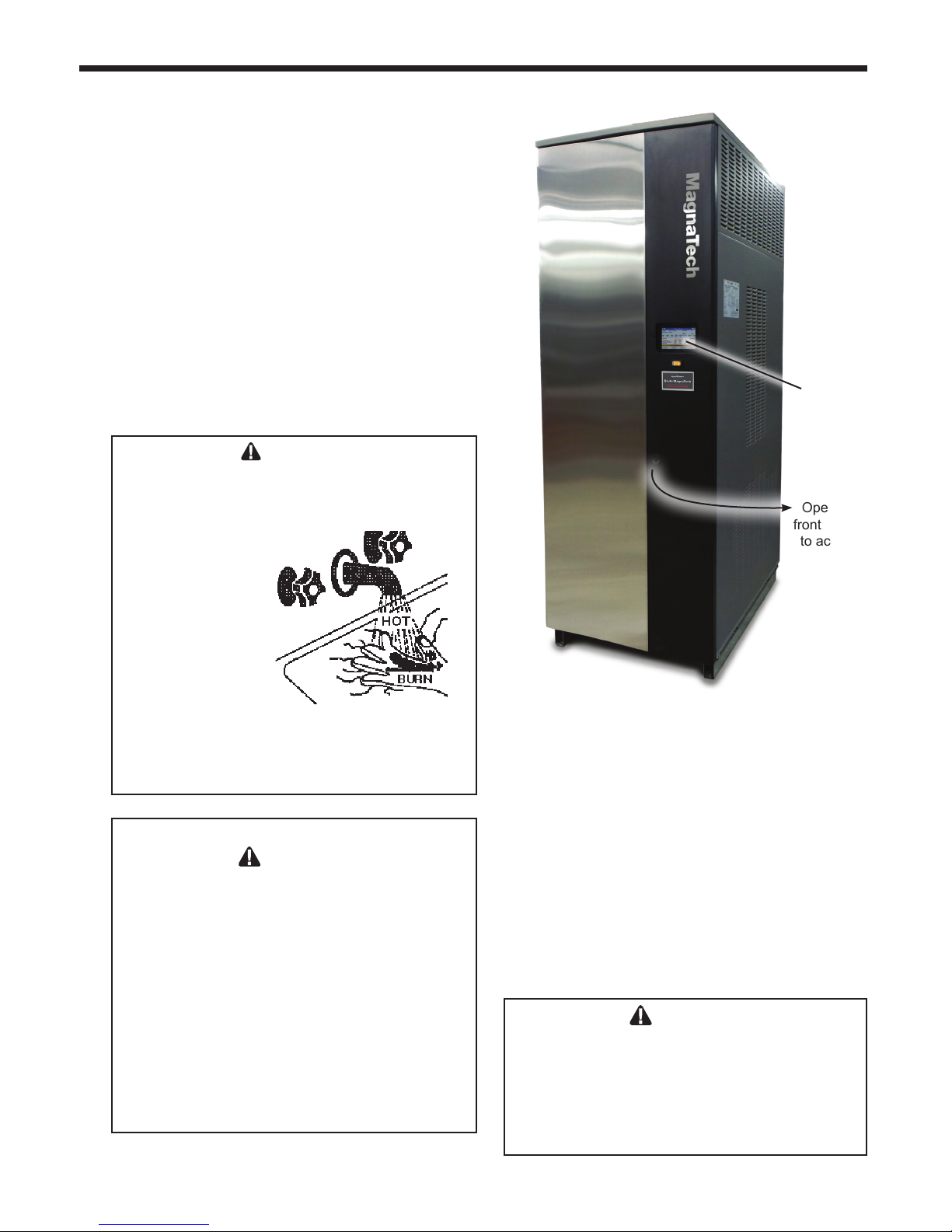
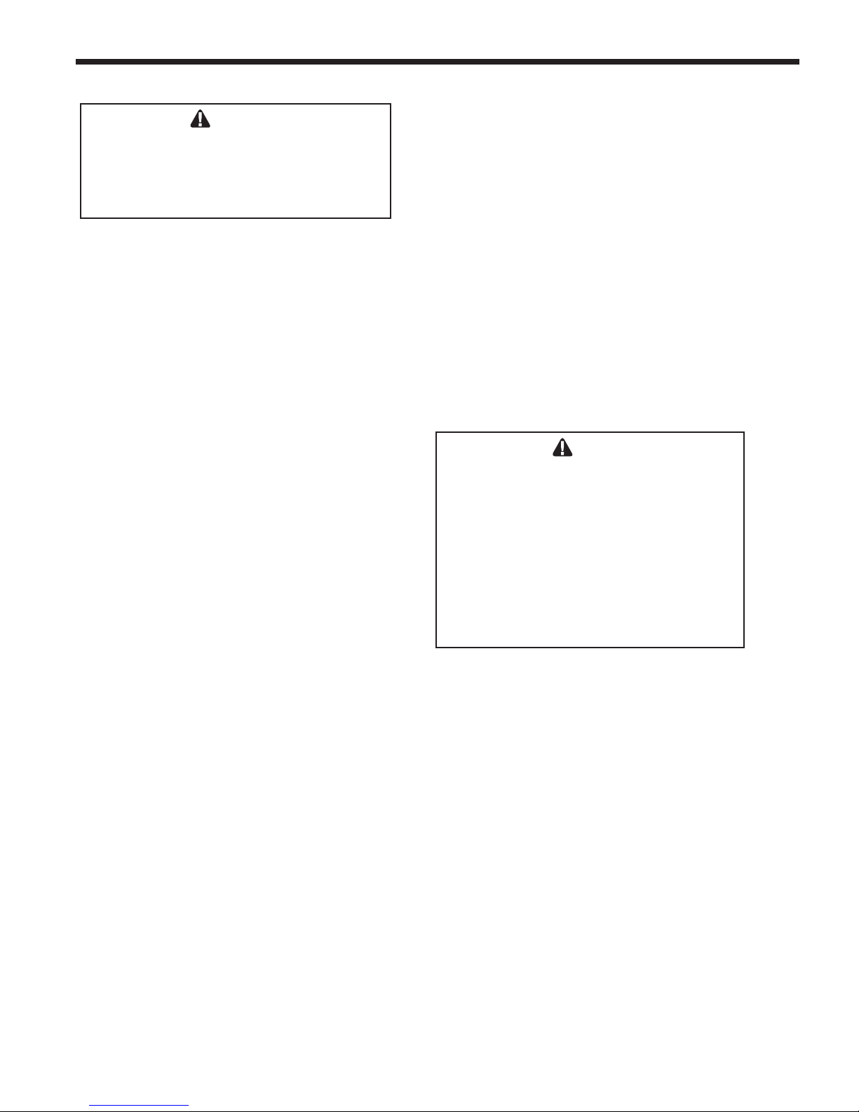
1.2 Safety Notes
DANGER
• Water temperature over 125°F (52°C) can cause
severe burns instantly or death from scalds.
• Children, disabled and elderly are at highest risk of
being scalded.
• See instruction manual before
setting temperature at
heating appliance.
• Feel water before
bathing or showering.
• If this appliance is used
to produce water that
could scald if too hot,
such as domestic hot water
use, adjust the outlet
control (limit) or use temperature limiting valves
to obtain a maximum water temperature of 125°F
(52°C).
Fire or Explosion Hazard
Improper conguration can cause fuel buildup and
explosion. Improper user operation may result in
property loss, severe physical injury, or death.
Any changes to safety-related conguration
parameters must only be done by experienced and/
or licensed burner/boiler operators and mechanics.
If any odor of gas is detected, or if the gas burner
does not appear to be functioning in a normal
manner, close the main gas shuto valve. Do not
shut o the power switch. Contact your heating
contractor, gas company, or factory representative.
WARNING
Page 1
Touch
Screen
Open the
front panel
to access
the Touch
Screen
e MagnaTech Appliance is protected against overpressurization. A pressure relief valve is included
with each MagnaTech.
e inlet gas pressure to the appliance must not
exceed 13” W.C. (3.2 kPa).
All installations must be made in accordance with
1) American National Standard Z223.1/NFPA54Latest Edition “National Fuel Gas Code” or 2) CSA
B149.1 “Natural Gas and Propane Installation Code”
and with the requirement of the local utility or other
authorities having jurisdiction. Such applicable
requirements take precedence over the general
instructions contained herein.
WARNING
Carbon Monoxide Hazard
Improper adjustment of the burners may lead to
poor combustion quality, increasing the amount
of carbon monoxide produced. Excessive carbon
monoxide levels may lead to personal injury or
death.
Page 6
Page 2
B
RADFORD WHITE
1
2 3 4 5 6 7 8 9 10 11 12 13 14
M G 1
B
SERIES
B M G
USAGE
H - HYDRONIC
V - VOLUME
WATER
SIZE
MBTU/h
1600
2000
2500
3000
3500
4000
FUEL
N - NATURAL
P - PROPANE
COUNTRY
CODE
X - USA/
CANADA
E - EXPORT
Not CSA approved
*
*
OPTIONS CODE
X - STANDARD
J - CSD-1
ELEC SYSTEM
A - 110V, 1Ø
B - 220V, 1Ø
C - 208V, 3Ø
D - 480V, 3Ø
E - 600V, 3Ø
ASME
X - “H” STAMP (MGH)
W - “HLW” STAMP (MGV)
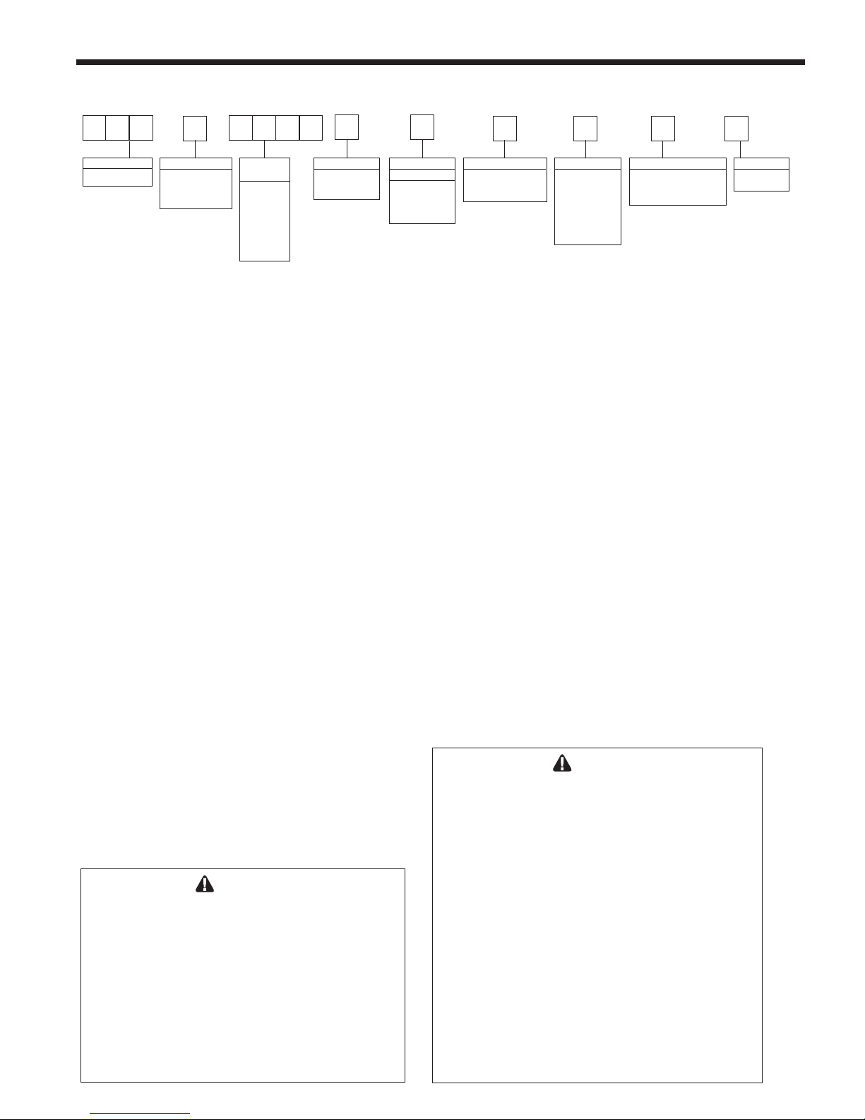
1.3 ModelIdentication
Model Nomenclature
Consult the rating plate on the unit. The
following information describes the model
number structure.
(1-3) Model Series Designation
B = Bradford White
M G = MagnaTech
(4) Usage
H = Hydronic
V = Volume Water
(5-8) Size
1 6 0 0 = 1,600,000 BTU/hr input
2 0 0 0 = 1,999,000 BTU/hr input
2 5 0 0 = 2,499,000 BTU/hr input
3 0 0 0 = 3,000,000 BTU/hr input
3 5 0 0 = 3,500,000 BTU/hr input
4 0 0 0 = 4,000,000 BTU/hr input
(9) Fuel
N = Natural Gas
P = LP Gas
(10) Country Code
X = USA / CANADA
E - Export (CE - non CSA)
(11) Option Code
X = Standard Unit
J = CSD1 Version
(12) Electrical System
A - 110V, (Single Phase)
B - 220V, (Single Phase)
C - 208V, (Three Phase)
D - 480V, (Three Phase)
E - 600V, (Three Phase)
(13) Additional Options
X - “H” STAMP (MGH)
W - “HLW” STAMP (MGV)
(14) Revision
1 = First
WARNING
Electrical Shock Hazard
Electrical shock can cause severe injury, death or property
damage. Disconnect the power supply before beginning
installation or changing the wiring to prevent electrical
shock or damage to the equipment. It may be necessary to
turn o more than one power supply disconnect.
All electrical wiring is to be done in accordance with
local codes, or in the absence of local codes, with: 1) e
National Electrical Code ANSI/NFPA No. 70 - latest
Edition, or 2) CSA STD. C22.1 “Canadian Electrical Code
- Part 1.” is appliance must be electrically grounded in
accordance with these codes.
Altitude: Gas input rating of the MagnaTech
shall be used for elevations up to 2000 ft (600
m). The input rating at elevations above 2000 ft
(600 m) shall be reduced at a rate of 4 percent
for each 1000 ft (300 m) above sea level before
selecting the equipment size.
1.4 Warranty
Bradford Whites MagnaTech boilers are
covered by a limited warranty. The owner
should complete the warranty registration at
http://www.Bradford White.com
ALL WARRANTY CLAIMS must be made by an
authorized Bradford White Corp. representative.
Claims must include the serial number and
model (this information can be found on the
rating plate). All claims must also include the
installation date and name of the installer.
Shipping costs are not included in the warranty
coverage.
WARNING
MagnaTech units must be installed in accordance
with the procedures detailed in this manual, or the
Bradford White Corp. warranty will be voided. e
installation must conform to the requirements of
the local jurisdiction having authority, and, in the
United States, to the latest edition of the National
Fuel Gas Code, ANSI Z223.1/NFPA54. In Canada,
the installation must conform to the latest edition of
CSA B149.1 Natural Gas and Propane Gas Installation
Code, and/or local codes. Where required by the
authority having jurisdiction, the installation of
MagnaTech boilers must conform to the Standard for
Controls and Safety Devices for Automatically Fired
Boilers, ANSI/ASME CSD-1. Any modications to
the boiler, its gas controls, or wiring may void the
warranty. If eld conditions require modications,
consult the factory representative before initiating
such modications.
REVISION
1 -FIRST
Page 7
MagnaTech
BOILERS AND VOLUME WATER HEATERS
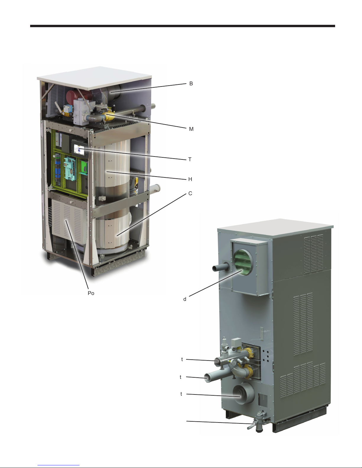
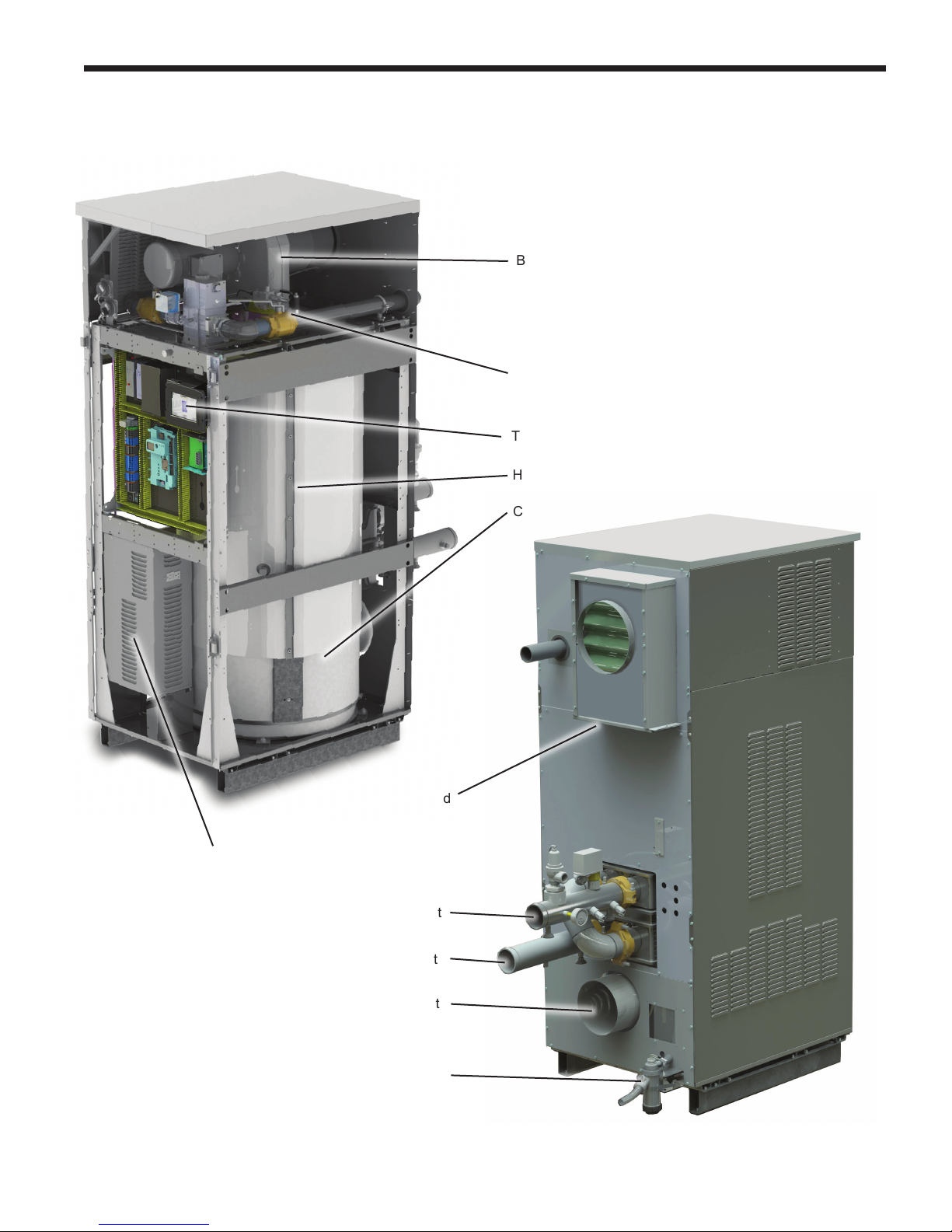
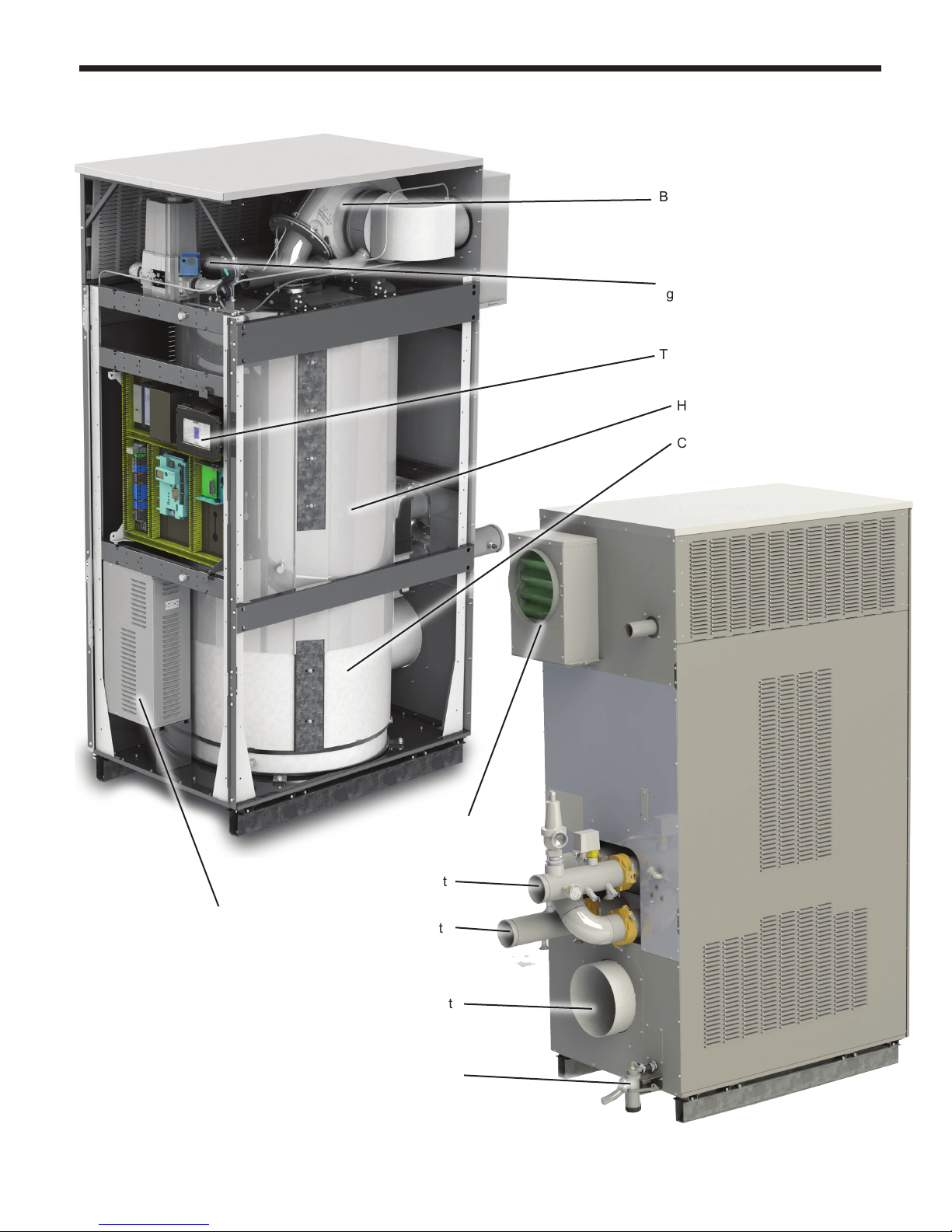
1.5 Unit Overviews
The next 3 pages give a visual reference to the basic
component locations of the Bradford White MagnaTech.
Blower
Manual
gas valve
Touch Screen
Heat Exchanger
Page 3
Power Pack
Condensing Unit
Air Intake and
Filter
Water Outlet
Models 1600 and 2000
Perspective from front left corner of unit.
Shown with front doors and left side
panels removed.
Water Inlet
Vent
Condensate
Trap
Perspective from opposite corner.
Page 8
Page 4
Blower
Manual
gas valve
Touch Screen
Heat Exchanger
B
RADFORD WHITE
Power Pack
Condensing Unit
Air Intake and
Filter
Water Outlet
Water Inlet
Models 2500 and 3000
Vent
Condensate
Trap
Page 9
MagnaTech
BOILERS AND VOLUME WATER HEATERS
Page 5
Blower
Manual
gas valve
(hidden behind main
gas valve)
Touch Screen
Heat Exchanger
Condensing Unit
Power Pack
Models 3500 and 4000
Air Intake and
Filter
Water Outlet
Water Inlet
Vent
Condensate
Trap
Page 10
Page 6
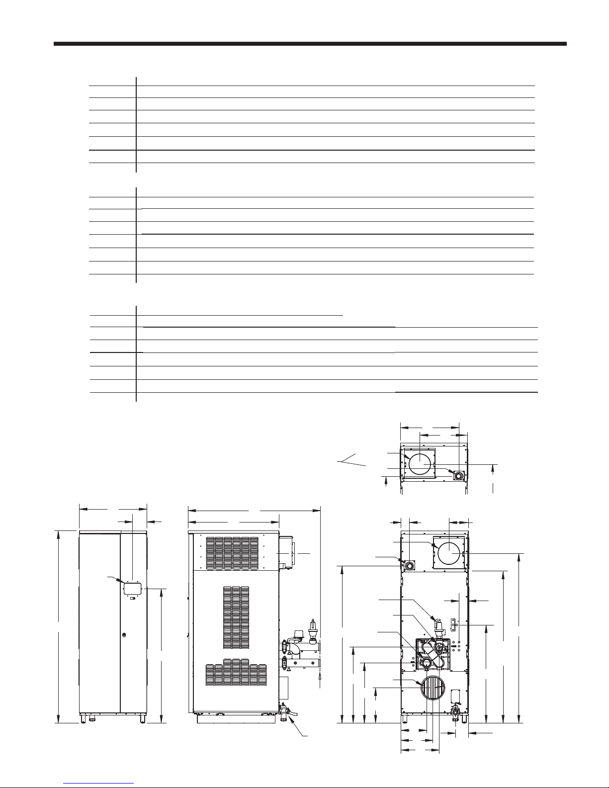
E
F
U
B
A
VIEW
REAR
N
Q
S
P
M
R
L
G
H
K
J
T
FRONT
VIEW
SIDE
VIEW
C
D
Condensate Trap
Contact
Factory
Oponal
Flanges,
Vent
Gas
6”x3.5”
Touchscreen
Display
Air Inlet
Pressure
Relief
Valve
Water
Outlet
‘Knock-
down’
Height
Water
Inlet
H
J
Gas
Air Inlet
Model 4000
The Model 4000 varies from other sizes in the locaon of it’s Air Inlet and Gas Supply.
G
K
VIEWREAR
Model
A B C D E F G H J K L M N P Q R S T U
Inches (cm ) Inches (cm ) Inches (cm )
1600
29.3 (75 ) 79.8 (203 ) 38 (96 ) 57.5 (147) 49.8 (126 ) 4.8 (12 ) 60.8 (154 ) 2.6 (7 ) 8.4 (21 ) 68.4 (171 ) 4 (10 ) 39.2 (100 ) 30.4 (77) 16 (41 ) 23 (58 ) 10.2 (26 ) 14 (36) 13 (33 ) 6.3 (16 ) 6 (15 ) 6 (15 ) 60.8 (154 )
2000
29.3 (75 ) 79.8 (203 ) 38 (96 ) 57.5 (147) 49.8 (126 ) 4.8 (12 ) 60.8 (154 ) 2.6 (7 ) 8.4 (21 ) 67.4 (171 ) 4 (10 ) 39.2 (100 ) 30.4 (77) 16 (41 ) 23 (58 ) 10.2 (26 ) 14 (36) 13 (33 ) 6.3 (16 ) 8 (20 ) 8 (20 ) 60.8 (154 )
2500 30.8 (78)
87 (221 ) 41.5 (105 ) 60.5 (154 ) 60.8 (154 ) 6.5 (16 ) 71 (180 ) 4 (10) 9.8 (25 ) 76.4 (194 ) 4.3 (11 ) 44.4 (113 ) 34.5 (88 ) 17.7 (45 ) 27.2 (69 ) 11.8 (30 ) 18.3 (46 ) 14.8 (38 ) 6 (15 ) 8 (20 ) 8 (20 ) 71.0 (180 )
3000 30.8 (78)
87 (221 ) 41.5 (105 ) 60.5 (154 ) 60.8 (154 ) 6.5 (16 ) 71 (180 ) 4 (10) 8.9 (23 ) 76.8 (195 ) 4.3 (11 ) 44.4 (113 ) 34.5 (88 ) 17.7 (45 ) 27.2 (69 ) 11.8 (30 ) 18.3 (46 ) 14.8 (38 ) 6 (15 ) 10 (25 ) 10 (25 ) 71.0 (180 )
3500
34.5 (88 ) 97 (246 ) 52 (133 ) 70 (178 ) 60.8 (154 ) 6.4 (16 ) 80.8 (205 ) 28.8 (73) 26.5 (67) 85.6 (217 ) 6.5 (16 ) 51.3 (130 ) 40 (102 ) 21.6 (55 ) 30.7 (78 ) 13 (33 ) 16 (41 ) 17.4 (44 ) 6.7 (17 )
4000
34.5 (88 ) 97 (246 ) 52 (133 ) 70 (178 ) 60.8 (154 ) 6.4 (16 ) 80.8 (205 ) 28.8 (73) 26.5 (67) 85.6 (217 ) 6.5 (16 ) 51.3 (130 ) 40 (102 ) 21.6 (55 ) 30.7 (78 ) 13 (33 ) 16 (41 ) 17.4 (44 ) 6.7 (17 ) 12 (30 ) 12 (30 ) 80.8 (205)
Model
A B C D E F G H J K L M N P Q R S T U
Inches (cm ) Inches (cm ) Inches (cm )
1600
29.3 (75 ) 79.8 (203 ) 38 (96 ) 57.5 (147 ) 49.8 (126 ) 4.8 (12 ) 60.8 (154 ) 2.6 (7 ) 8.4 (21 ) 68.4 (171 ) 4 (10 ) 39.2 (100 ) 30.4 (77 ) 16 (41) 23 (58 ) 10.2 (26) 14 (36 ) 13 (33 ) 6.3 (16 ) 6 (15 ) 6 (15 ) 60.8 (154 )
2000
29.3 (75 ) 79.8 (203 ) 38 (96 ) 57.5 (147 ) 49.8 (126 ) 4.8 (12 ) 60.8 (154 ) 2.6 (7 ) 8.4 (21 ) 67.4 (171 ) 4 (10 ) 39.2 (100 ) 30.4 (77 ) 16 (41) 23 (58 ) 10.2 (26) 14 (36 ) 13 (33 ) 6.3 (16 ) 8 (20 ) 8 (20 ) 60.8 (154 )
2500 30.8 (78)
87 (221 ) 41.5 (105 ) 60.5 (154 ) 60.8 (154 ) 6.5 (16 ) 71 (180 ) 4 (10) 9.8 (25 ) 76.4 (194 ) 4.3 (11 ) 44.4 (113 ) 34.5 (88 ) 17.7 (45 ) 27.2 (69 ) 11.8 (30 ) 18.3 (46 ) 14.8 (38 ) 6 (15 ) 8 (20 ) 8 (20 ) 71.0 (180 )
3000 30.8 (78)
87 (221 ) 41.5 (105 ) 60.5 (154 ) 60.8 (154 ) 6.5 (16 ) 71 (180 ) 4 (10) 8.9 (23 ) 76.8 (195 ) 4.3 (11 ) 44.4 (113 ) 34.5 (88 ) 17.7 (45 ) 27.2 (69 ) 11.8 (30 ) 18.3 (46 ) 14.8 (38 ) 6 (15 ) 10 (25 ) 10 (25 ) 71.0 (180 )
3500
34.5 (88 ) 97 (246 ) 52 (133 ) 70 (178 ) 60.8 (154 ) 6.4 (16 ) 80.8 (205 ) 28.8 (73) 26.5 (67) 85.6 (217 ) 6.5 (16 ) 51.3 (130 ) 40 (102 ) 21.6 (55 ) 30.7 (78 ) 13 (33 ) 16 (41 ) 17.4 (44 ) 6.7 (17 )
4000
34.5 (88 ) 97 (246 ) 52 (133 ) 70 (178 ) 60.8 (154 ) 6.4 (16 ) 80.8 (205 ) 28.8 (73) 26.5 (67) 85.6 (217 ) 6.5 (16 ) 51.3 (130 ) 40 (102 ) 21.6 (55 ) 30.7 (78 ) 13 (33 ) 16 (41 ) 17.4 (44 ) 6.7 (17 ) 12 (30 ) 12 (30 ) 80.8 (205)
Vent Ø
Air Inlet Ø
10 (25) 10 (25)
Vent Ø
Air Inlet Ø
10 (25) 10 (25)
80.8 (205)
Water Gas
Condensate
Connection Connect ion Line
3" Groove Loc k (or flange)
2" NPT 1"
3" Groove Loc k
(or flange)
2" NPT 1"
3" Groove Loc k
(or flange)
2" NPT 1"
3" Groove Loc k
(or flange)
2" NPT 1"
4" Groove Loc k (or flange)
2" NPT 1"
4" Groove Loc k
(or flange)
2" NPT 1"
1.6 Dimensions
'Knock-
down'
Height
B
RADFORD WHITE
MagnaTech
Models 3500 and 4000 differ from the other sizes in the location of their Air Inlet and Gas Supply.
Figure 1. Dimensions
Models 3500 / 4000
H2359210D
Page 11
MagnaTech
BOILERS AND VOLUME WATER HEATERS
Page 7
1.7 Unpacking
The MagnaTech is shipped in a single crate.
Remove all packing and tie-down materials.
Section 2
LOCATING THE APPLIANCE
2.1 Locating the Appliance
The MagnaTech may be installed indoors or
outdoors. If installing outdoors in a location
that may experience freezing temperatures,
precautions must be taken to prevent water in
the heat exchanger and condensate inside and
outside of the boiler from freezing. Damage due
to freezing water or condensate is not covered by
the warranty.
Choose a location for the unit which allows
clearances on all sides for maintenance and
inspection. See Table 1. Always install the unit on
a rm, level surface.
The unit should not be located in an area
where leakage of any connections will result in
damage to the area adjacent to the appliance,
or to lower oors of the structure.
When this type of location is not available,
install a suitable drain pan, adequately drained,
under the appliance.
The appliance is design-certied by CSA-
International for installation on combustible
ooring; in basements; in utility rooms or
alcoves. MagnaTech boilers must never be
installed on carpeting. The location for the
appliance should be chosen with regard to the
vent pipe lengths and external plumbing.
The unit shall be installed such that the gas
ignition system components are protected from
water (dripping, spraying, rain, etc.) during
operation and service (circulator replacement,
control replacement, etc.).
When vented vertically, the MagnaTech must
be located as close as practical to the vertical
section of the vent. If the vent terminal and/or
combustion air terminal terminate through a wall,
and there is potential for snow accumulation in
the local area, both terminals should be installed
at an appropriate level above grade or the
maximum expected snow line.
The dimensions and requirements that are
shown in Table 1 should be met when choosing
the locations for the appliance.
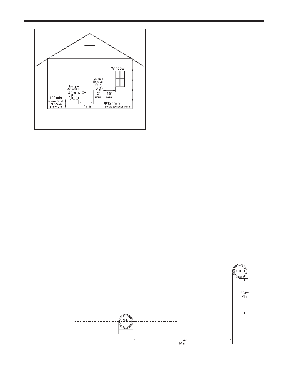
Note - When located on the same wall, the
MagnaTech combustion air intake terminal must be
installed a minimum of 12” (30cm) below the exhaust
terminal. There must also be a minimum horizontal
distance from intake to the exhaust terminal
of 84” (213cm) See Figure 4
APPLIANCE SUGGESTED SERVICE ACCESS CLEARANCE
SURFACE INCHES CM
Front 24 61
Left Side 8 20
Right Side 8 20
Back 24 61
Top, 1600 & 2000 12 30
Top, 2500 & 3000 15 38
Top, 4000 24 61
APPLIANCE REQUIRED CLEARANCE TO COMBUSTIBLES
SURFACE INCHES CM
Front 18 45
Left Side 4 15
Right Side 4 15
Back 11 15
Top 1 2.5
Vent 1 2.5
Table 1. Clearances
INTAKE / EXHAUST
MAX EQUIVALENT
SIZE DIAMETER F T. M
1600 6” 100 30
2000 & 2500 8” 100 30
3000 & 3500 10” 100 30
4000 12” 100 30
Installations in the U.S. require exhaust vent pipe that is CPVC
complying with ANSI/ASTM D1785 F441, polypropylene
complying with ULC S636, or stainless steel complying with
UL1738. Installations in Canada require exhaust vent pipe that
is certied to ULC S636.
Intake (air) pipe must be PVC or CPVC that complies with
ANSI/ASTM D1785 F441, ABS that complies with ANSI/ASTM
D1527, stainless steel, or galvanized material.
To calculate max equivalent length, measure the linear feet of
the pipe, and add 5 feet (1.5 m) for each elbow used.
2.2 Correct Vent Distance from
Outside Wall or Roof Termination
Table 2. Vent / Air Pipe Sizes
Page 12
Page 8
(Place in section 3.1)
Screen for horizontal galvanized air pipe D2012104 D2012101 D2012101 D2012102 D2012103 D2012103
Screen for horizontal PVC air pipe CA012004 CA012001 CA012001 CA012002 CA012003 CA012003
Screen for horizontal polypropylene air pipe CA012204 CA012201 CA012201 CA012202 CA012203 CA012203
Screen for vertical galvanized air pipe D2012204 D2012201 D2012201 D2012202 D2012203 D2012203
Section 3
VENTING AND COMBUSTION AIR
3.1 Combustion Air
MagnaTech boilers and water heaters
must have provisions for combustion and
ventilation air in accordance with the applicable
requirements for Combustion Air Supply and
Ventilation in the National Fuel Gas Code,
ANSI Z223 1; or in Canada, the Natural Gas
and Propane Installation Code, CSA B149.1.
All applicable provisions of local building codes
must also be adhered to.
A MagnaTechs can take combustion air
from the space in which it is installed, or
the combustion air can be ducted directly to
the unit. Ventilation air must be provided in
either case.
3.1.1 Combustion Air From Room
In the United States, the most common
requirements specify that the space shall
communicate with the outdoors in accordance
with Method 1 or 2. (See the following
descriptions.) Where ducts are used, they shall
B
RADFORD WHITE
be of the same cross-sectional area as the free
area of the openings to which they connect.
Method 1: Two permanent openings, one
commencing within 12” (300 mm) of the top
and one commencing within 12” (300 mm) of
the bottom, of the enclosure shall be provided.
The openings shall communicate directly, or
by ducts, with the outdoors or spaces that
freely communicate with the outdoors. When
directly communicating with the outdoors,
or when communicating to the outdoors
through vertical ducts, each opening shall
have a minimum free area of 1 square inch
per 4000 Btu/hr (550 square mm/kW) of total
input rating of all equipment in the enclosure.
When communicating to the outdoors through
horizontal ducts, each opening shall have a
minimum free area of not less than 1 square
inch per 2000 Btu/hr (1100 square mm/kW)
of total input rating of all equipment in the
enclosure.
Method 2: One permanent opening,
Screen for vertical PVC air pipe CA012404 CA012401 CA012401 CA012402 CA012403 CA012403
Screen for vertical polypropylene air pipe CA012604 CA012601 CA012601 CA012602 CA012603 CA012603
Table 3. Ducted Air Accessories
CPVC, sch. 40 ANSI/ASTM F441
Single wall galv. steel 26 gauge
Table 4. Required Combustion Air Pipe Material
Polypropylene ULC S636 Class 2C
Model 1600 Model 2000 Model 2500 Model 3000 Model 3500 Model 4000
Material United States Canada
ABS ANSI/ASTM D1527 The air pipe material must be chosen based upon
PVC, sch. 40 ANSI/ASTM D1785 or D2665
the intended application of the boiler, and must
be installed according to the vent manufacturer’s
installation instructions.
Page 13
MagnaTech
BOILERS AND VOLUME WATER HEATERS
commencing within 12” (300 mm) of the top of
the enclosure, shall be permitted. The opening
shall directly communicate with the outdoors
or shall communicate through a vertical or
horizontal duct to the outdoors or spaces that
directly communicate with the outdoors and
shall have a minimum free area of 1 square inch
per 3000 Btu/hr (734 square mm/kW) of the
total input rating of all equipment located in the
enclosure. This opening must not be less than
the sum of the areas of all vent connectors in
the conned space.
Other methods of introducing combustion and
ventilation air are acceptable, providing they
conform to the requirements in the applicable
codes listed above.
In Canada, consult local building and safety
codes or, in absence of such requirements,
follow CAN/CSA B149.
3.1.2 Ducted Combustion Air
The combustion air can be taken through the
wall, or through the roof. Bradford White offers
accessories to use with ducted air systems, as
shown in Table 3.
See Table 4 to select the appropriate diameter
air pipe. When taken from the roof, a eld-
supplied rain cap or an elbow arrangement
must be used to prevent entry of rain water.
(See Figure 6).
Use ABS, PVC, CPVC, polypropylene, stainless
steel, or galvanized pipe for the combustion
air intake. (See Table 4) The intake must be
sized per Table 2. Route the intake to the boiler
as directly as possible. Seal all joints. Provide
adequate hangers. The unit must not support
the weight of the combustion air intake pipe.
The maximum equivalent pipe length allowed is
100 feet (30 m).
Each elbow is considered to be 5 feet (1.5m)
Page 9
The connection for the intake air pipe is on the
back panel.
In addition to air needed for combustion, air
shall also be supplied for ventilation, including
air required for comfort and proper working
conditions for personnel. Refer to the applicable
codes.
3.2 Venting
WARNING
Selection of improper vent materials for
installations that are installed in closets, or will be
operated in high ambient temperature levels, may
lead to property damage, personal injury, or death.
WARNING
Failure to use the appropriate vent material,
installation techniques, or glues and sealants
could lead to vent failure causing property
damage, personal injury or death.
When using polypropylene or stainless steel
materials in horizontal duct congurations, a
single elbow must be installed on the end of the
air inlet to act as an outdoor terminal. In vertical
duct applications, two elbows must be installed
on the end of the inlet to act as a vent terminal.
When elbows are use as terminals, appropriate
screens must be installed to prevent blockage.
The elbow(s) required for termination are not
included in the kits sown in Table 3
Page 14
Page 10
(Place in section 3.1)
Model 1600 Model 2000 Model 2500 Model 3000 Model 3500 Model 4000
Screen for horizontal galvanized air pipe D2012104 D2012101 D2012101 D2012102 D2012103 D2012103
Screen for horizontal PVC air pipe CA012004 CA012001 CA012001 CA012002 CA012003 CA012003
Screen for horizontal polypropylene air pipe CA012204 CA012201 CA012201 CA012202 CA012203 CA012203
Screen for vertical galvanized air pipe D2012204 D2012201 D2012201 D2012202 D2012203 D2012203
Screen for vertical PVC air pipe CA012404 CA012401 CA012401 CA012402 CA012403 CA012403
Screen for vertical polypropylene air pipe CA012604 CA012601 CA012601 CA012602 CA012603 CA012603
Table 3a - Ducted Air Accessories
(Place in section 3.2)
Horizontal vent terminal for stainless steel D2012004 D2012001 D2012001 D2012002 D2012003 D2012003
Screen for vertical CPVC vent CA012504 CA012501 CA012501 CA012502 CA012503 CA012503
B
RADFORD WHITE
WARNING
All venting must be installed according to this
manual and any other applicable local codes,
including but not limited to, ANSI Z223.1/NFPA 54,
CSA B149.1, CSAB149.2 and ULC S636. Failure
to follow this manual and applicable codes may
lead to property damage, severe injury, or death.
If the system temperatures are unknown at
the time of installation, class IIC or higher
venting material is recommended.
The MagnaTech is a Category IV appliance and
may be installed with the standards listed on
Table 6.
The unit’s vent can terminate through the roof,
or through an outside wall.
All installations must be done following the vent
supplier’s recommended installation techniques.
If these are not available, refer to the Bradford
White recommendations for the material used.
NOTE: For Category IV boilers, have
horizontal runs sloping upwards not less than
1/4 inch per foot (21 mm/m) from the boiler to
the vent terminal; be installed so as to prevent
accumulation of condensate; and, where
necessary, have means provided for drainage
of condensate.
ATTENTION: Pour la catégorie IV, les
chaudières ont horizontal en pente vers
le haut au moins 1/4 de pouce par pied
(21 mm/m) à partir de la chaudière pour
l’évent borne; être installé de façon à éviter
l’accumulation de condensats; et, le cas
échéant, ont des moyens prévus pour
l’évacuation des condensats.
This will allow the condensate to run back to
the MagnaTech to drain. Route the vent pipe
to the heater as directly as possible. Seal all
joints. Provide adequate hangers as required in
the venting system manufacturer’s Installation
Instructions, or at least every 4 feet.
The unit must not support the weight of the
vent pipe. The maximum equivalent pipe
length allowed is 100 feet (30m). Each elbow
Screen for horizontal CPVC vent CA012104 CA012101 CA012101 CA012102 CA012103 CA012103
Screen for vertical stainless steel vent D2012304 D2012301 D2012301 D2012302 D2012303 D2012303
Table 5. Vent Accessories
Material United States Canada
Stainless steel UL 1738 Venting must be ULC S636 certied for use as
CPVC, sch 40 ANSI/ASTM F441
Polypropylene
Pending APPROVAL
Table 6. Required Exhaust Vent Material
Model 1600 Model 2000 Model 2500 Model 3000 Model 3500 Model 4000
Installation Standards
venting material. The venting material class must
be chosen based upon the intended application
of the boiler, and must be installed according to
ULC S636 Class 2C
the maximum ue gas temperature and the vent
manufacturer’s instructions.
Page 15
MagnaTech
BOILERS AND VOLUME WATER HEATERS
is considered to be 5 feet (1.5m). Bradford
White offers accessories to use with horizontal
and vertical exhaust vent systems, as shown in
Table 5
3.2.1 Common Venting
The MagnaTech can be common vented,
however, the common venting must be a
professionally designed and approved system.
MagnaTech units are never permitted to share a
vent with any Catagory 1 appliances.
3.2.3 Venting Requirements Unique to
Canada
MagnaTech boilers and water heaters are Vent
Category IV appliances. Per the requirements
of CAN/CSA-B149.1, only BH vent systems
can be connected to these units and such vent
systems, either ULC S636 certied stainless
steel or other ULC S636 certied BH vent
(eg. plastics) must be installed per the vent
manufacturer’s certied installation instructions.
It is the responsibility of the appropriately
licensed technician installing this MagnaTech to
use ULC S636 certied vent material consistent
with the requirements as described in the
Venting and Combustion Air section.
Class I venting systems are suitable for gas-red
appliances producing ue gas temperature of more
than 135°C, but not more than 245°C.
Class II venting systems are suitable for gas-red
appliances producing ue gas temperatures of 135°C
or less.
Class II venting systems are further classied into
four temperature ratings as follows:
Page 11
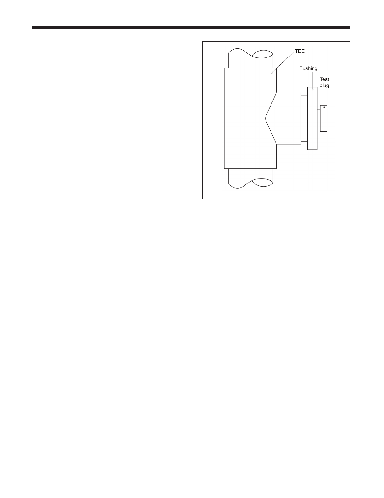
Figure 2. Test Port
the ULC S636 certied vent system is preferred.
However, if one is not available with the certied
vent system, Bradford White suggests using a
tee with the branch connection sized to allow
for insertion of a ue gas analyzer probe. The
branch connection must be resealable with a
cap or other means to ensure the vent system
remains sealed. (See Figure 2)
Consideration must be given to the placement
and orientation of the ue gas sampling port to
ensure that condensate is free to ow back into
the MagnaTech and not collect anywhere in the
vent system - including in the ue gas sampling
port.
A Up to and including 65°C / 149°F
B Up to and including 90°C / 194°F
C Up to and including 110°C / 230°F and
D Up to and including 135°C / 275°F
Flue Gas Sampling Port -
It is also the responsibility of the installer to
ensure that a ue gas sampling port is installed
in the vent system. This ue gas sampling port
must be installed near the ue connection of the
MagnaTech: within 2 feet of the ue connection.
There is no ue gas sampling port internal to
the MagnaTech, so one must be installed in the
vent system external to the MagnaTech. A ue
gas sampling port available as a component of
Exhaust Vent Terminal -
An exhaust vent terminal must be installed.
If an exhaust vent terminal is not available
with the certied vent system, Bradford White
suggests the use of a coupler tting from
the certied vent system into which the vent
terminal screen can be installed. Be sure to
install and terminate both vent and combustion
air pipes per the instructions in this section.
3.3 Locating the Vent and Combustion
Air Terminals
3.3.1 Side Wall Vent Terminal
The appropriate Bradford White side wall vent
terminal must be used. The terminal must be
Page 16
Page 12
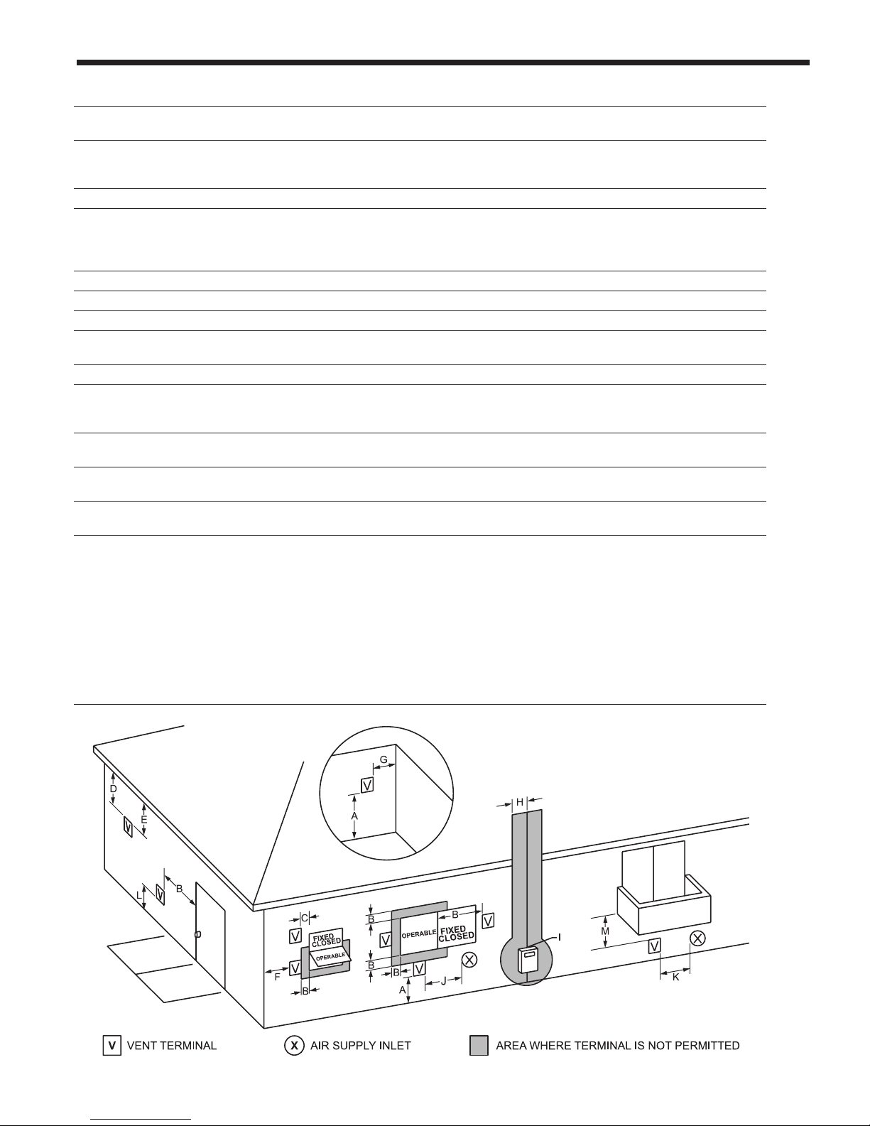
U.S. Installations (see note 1) Canadian Installations (see note 2)
A= Clearance above grade, veranda, porch, 12 inches (30 cm) 12 inches (30 cm)
deck, or balcony See note 6 See note 6
B= Clearance to window or door that may be Direct vent only: 12 inches (30 cm); 36 inches (91 cm)
opened Other than Direct vent: 4 ft (1.2m) below or to
side of opening; 1 ft (30 cm) above opening
C= Clearance to permanently closed window See note 4 See note 5
D= Vertical clearance to ventilated soft located
above the terminal within a horizontal See note 4 See note 5
distance of 2 feet (61 cm) from the center
line of the terminal
E= Clearance to unventilated soft See note 4 See note 5
F= Clearance to outside corner See note 4 See note 5
G= Clearance to inside corner See note 4 See note 5
H= Clearance to each side of center line 3 feet (91 cm) within a height 15 feet
extended above meter/regulator assembly See note 4 above the meter/regulator assembly
I= Clearance to service regulator vent outlet See note 4 3 feet (91 cm)
J= Clearance to nonmechanical air supply Direct vent only: 36” (91cm)
inlet to building or the combustion air inlet Other than Direct vent: 4 ft (1.2m) below 36 inches (91 cm)
to any other appliance or to side of opening; 1 ft (30 cm) above opening
K= Clearance to a mechanical air supply inlet 3 feet (91 cm) above if within 10 feet (3 m) 6 feet (1.83 m)
horizontally
L= Clearance above paved sidewalk or paved Vent termination not allowed in this location 7 ft (2.1 m)
driveway located on public property for category IV appliances. See note 5
M= Clearance under veranda, porch, deck, See note 4 12 inches (30 cm)
or balcony See note 5
Notes:
1. In accordance with the current ANSI Z223.1 / NFPA 54 National Fuel Gas Code.
2. In accordance with the current CAN/CSA-B149 Installation Codes.
3. Permitted only if veranda, porch, deck, or balcony is fully open on a minimum of two sides beneath the oor.
4. For clearances not specied in ANSI Z223.1 / NFPA 54, clearance is in accordance with local installation codes and the
requirements of the gas supplier.
5. For clearances not specied in CAN/CSA-B149, clearance is in accordance with local installation codes and the requirements of the
gas supplier.
6. IMPORTANT: All terminals must be placed so that they remain a minimum 12” above expected snow line. Local codes may have
more specic requirements, and must be consulted.
B
RADFORD WHITE
Figure 3. Combustion Air and Vent Through Side Wall
*When vent terminal is less than 10 feet (3 m) horizontally
from a forced air inlet, the terminal must be at least 3 feet
(0.9 m) above the air inlet. (US only)
Page 17
MagnaTech
IMPORTANT: All terminals must be placed so that they remain at least 12”
above the expected snow line. Local codes may have more specic
requirements, and must be consulted. Refer to the NFPA54 National Fuel Gas
Code and your local codes for all required clearances for venting.
BOILERS AND VOLUME WATER HEATERS
84
Page 13
windows or near doors.
5. Locate the vent terminal so that it
cannot be blocked by snow. The
installer may determine that a vent
terminal must be higher than the
minimum shown in codes, depending
upon local conditions.
6. Locate the terminal so the vent exhaust
does not settle on building surfaces or
other nearby objects. Vent products may
damage surfaces or objects.
7. If the boiler or water heater uses ducted
combustion air from an intake terminal
located on the same wall, see See Figure
5 and Figure 4 for proper spacing and
orientation.
Figure 5. Multiple Side-Wall Terminals, Air and
Vent
located in accordance with ANSI Z223.1/NFPA
54 and applicable local codes. In Canada, the
installation must be in accordance with CSA
B149.1 or .2 and local applicable codes.
Consider the following when installing the
terminal:
1. Figure 4 shows the requirements for
mechanical vent terminal clearances for
the U.S. and Canada.
2. Vent terminals for condensing appliances
or appliances with condensing vents
are not permitted to terminate above a
public walkway, or over an area where
condensate or vapor could create a
nuisance or hazard.
3. Locate the vent terminal so that vent gases
cannot be drawn into air conditioning
system inlets.
4. Locate the vent terminal so that vent gases
cannot enter the building through doors,
windows, gravity inlets or other openings.
Whenever possible, avoid locations under
3.3.2 Side Wall Combustion Air Terminal
Consider the following when installing the
terminal.
1. Do not locate the air inlet terminal near a
source of corrosive chemical fumes (e.g.,
cleaning uid, chlorine compounds, etc.).
2. Locate the terminal so that it will not
be subject to damage by accident or
vandalism. It must be at least 7 feet ( 2.1
m) above a public walkway.
3. Locate the combustion air terminal so that
it cannot be blocked by snow. The National
Fuel Gas Code requires that it be at least
12”
84”
213
Figure 4. Minimum Venting Distance
Page 18
Page 14
*
12 inches (30 cm) above grade, but the
installer may determine it should be higher,
depending upon local conditions.
4. If the MagnaTech is side-wall vented to the
same wall, use Figure 4 to determine the
proper mounting locations.
5. Multiple vent kits should be installed such
that the horizontal distance between outlet
group and inlet group is 84” (213 cm).
(See Figure 5)
6. The vent outlet must be at least 12” above
the top of the air inlet, and must be at least
84” (213 cm) horizontally from the air inlet.
(See Figure 5).
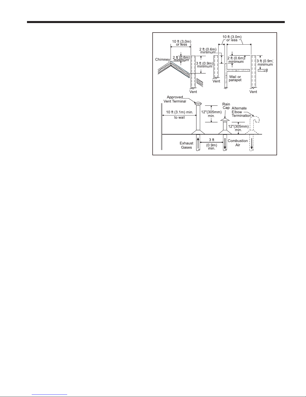
3.3.3 Vertical Vent Terminal
When the unit is vented through the roof, the
vent must extend at least 3 feet (0.9 m) above
the point at which it penetrates the roof. It must
extend at least 2 feet (0.6 m) higher than any
portion of a building within a horizontal distance
of 10 feet (3.0 m), and high enough above the
roof line to prevent blockage from snow. The
vent terminal offered with the MagnaTech can be
used in both vertical and horizontal applications.
When the combustion air is taken from the roof,
the combustion air must terminate at least 12”
(30 cm) below the vent terminal.
3.3.4 Vertical Combustion Air Terminal
When combustion air is taken from the roof, a
eld-supplied rain cap or an elbow arrangement
must be used to prevent entry of rain water.
The opening on the end of the terminal must be
at least 12” (30 cm) above the point at which it
penetrates the roof, and high enough above the
roof line to prevent blockage from snow. When
the vent terminates on the roof, the combustion
air must terminate at least 12” (30 cm) below
the vent terminal.
3.3.5 Installations in the Commonwealth
of Massachusetts
In Massachusetts the following items
are required if the side-wall exhaust vent
termination is less than seven (7) feet above
nished grade in the area of the venting,
including but not limited to decks and porches.
(From Massachusetts Rules and regulations
248 CMR 5.08.)
1. Installation of Carbon Monoxide
Detectors
At the time of installation of the side wall
B
RADFORD WHITE
*
*
*
In Canada, refer to CAN/CSA B199.1
*
*
Figure 6. Combustion Air and Vent Through Roof
*
vented gas fueled appliance, the installing
plumber or gas-tter shall observe that a
hard-wired carbon monoxide detector with
an alarm battery back-up is installed on
the oor level where the gas appliance is
to be installed. In addition, the installing
plumber or gastter shall observe that a
battery operated or hard-wired carbon
monoxide detector with an alarm is installed
on each additional level of the dwelling,
building or structure served by the side-wall
horizontally vented gas fueled equipment.
It shall be the responsibility of the property
owner to secure the services of qualied
licensed professionals for installation of
hard-wired carbon monoxide detectors.
a. In the event that the side-wall horizontally
vented gas fueled equipment is installed
in a crawl space or an attic, the hard-wired
carbon monoxide with alarm and battery
back-up may be installed on the next
adjacent oor level.
b. In the event that the requirements of the
subdivision cannot be met at the time of
completion of installation, the owner shall
have a period of thirty (30) days to comply
with the above requirements, provided,
however, that during said thirty (30) day
period, a battery operated carbon monoxide
detector with an alarm be installed.
Page 19

MagnaTech
BOILERS AND VOLUME WATER HEATERS
2. Approved Carbon Monoxide Detectors
Each carbon monoxide detector shall
comply with NFPA 720 and be ANSI/UL
2034 listed and IAS certied.
3. Signage
A metal or plastic identication plate shall
be permanently mounted to the exterior of
the building at a minimum height of eight
(8) feet above grade directly in line with the
exhaust vent terminal for horizontally vented
gas fueled heating appliance or equipment.
The sign shall read, in print no less than
one-half (1/2) inch in size: “GAS VENT
DIRECTLY BELOW, KEEP CLEAR OF ALL
OBSTRUCTIONS.”
4. Inspection
The state or local gas inspector of the
side-wall horizontally vented gas fueled
appliance shall not approve the installation
unless, upon inspection, the inspector
observes carbon monoxide detectors and
signage installed in accordance with the
provisions of 248 CMR 5.08(2)(a) 1-4.
3.4 Common Vent Test
Note -This section does not describe a method
for common venting MagnaTech’s. It describes
what must be done when a unit is removed from
a common vent system. MagnaTech’s require
special vent systems and fans for common vent.
Contact the factory if you have questions about
common venting MagnaTech’s.
When an existing boiler is removed from a
common venting system, the common venting
system is likely to be too large for proper
venting of the appliances remaining connected
to it.
Page 15
At the time of removal of an existing boiler,
the following steps shall be followed with each
appliance remaining connected to the common
venting system placed in operation, while the other
appliances remaining connected to the common
venting system are not in operation.
1. Seal any unused openings in the common
venting system.
2. Visually inspect the venting system for proper
size and horizontal pitch and determine
there is no blockage or restriction, leakage,
corrosion or other deciencies which could
cause an unsafe condition.
3. Insofar as is practical, close all building doors
and windows and all doors between the space
in which the appliances remaining connected
to the common venting system are located
and other spaces of the building. Turn on
any clothes dryers and any appliance not
connected to the common venting system.
Turn on any exhaust fans, such as range
hoods and bathroom exhausts, so they will
operate at maximum speed. Do not operate
a summer exhaust fan. Close replace
dampers.
4. Place in operation the appliance being
inspected. Follow the lighting instructions.
Adjust thermostat so appliance will operate
continuously.
5. Test for spillage at the draft hood relief
opening after ve minutes of main burner
operation. Use the ame of a match or candle,
or smoke from a cigarette, cigar or pipe.
6. After it has been determined that each
appliance remaining connected to the
common venting system properly vents when
tested as outlined above, return the doors,
windows, exhaust fans, replace dampers
and any other gas burning appliance to their
previous conditions of use.
7. Any improper operation of the common
venting system should be corrected so the
installation conforms with the National Fuel
Gas Code, ANSI Z223.1/NFPA 54 and/or
CAN/CSA B149.1, National Gas and Propane
Installation Code. When resizing any portion
of the common venting system, the common
Page 20

Page 16
(Place in section 3.1)
Model 1600 Model 2000 Model 2500 Model 3000 Model 3500 Model 4000
Screen for horizontal galvanized air pipe D2012104 D2012101 D2012101 D2012102 D2012103 D2012103
Screen for horizontal PVC air pipe CA012004 CA012001 CA012001 CA012002 CA012003 CA012003
Screen for horizontal polypropylene air pipe CA012204 CA012201 CA012201 CA012202 CA012203 CA012203
Screen for vertical galvanized air pipe D2012204 D2012201 D2012201 D2012202 D2012203 D2012203
Screen for vertical PVC air pipe CA012404 CA012401 CA012401 CA012402 CA012403 CA012403
Screen for vertical polypropylene air pipe CA012604 CA012601 CA012601 CA012602 CA012603 CA012603
Table 3a - Ducted Air Accessories
(Place in section 3.2)
Model 1600 Model 2000 Model 2500 Model 3000 Model 3500 Model 4000
Horizontal vent terminal for stainless steel D2012004 D2012001 D2012001 D2012002 D2012003 D2012003
Screen for horizontal CPVC vent CA012104 CA012101 CA012101 CA012102 CA012103 CA012103
Screen for vertical stainless steel vent D2012304 D2012301 D2012301 D2012302 D2012303 D2012303
Screen for vertical CPVC vent CA012504 CA012501 CA012501 CA012502 CA012503 CA012503
Table 3* - Vent Accessories
(Place in section 3.5)
Air intake screen for unit placed outdoors CA0011904 CA011901 CA011901 CA011902 CA0011903 CA0011903
Vent terminal for unit placed outdoors CA011803 CA011801 CA011801 CA011802 CA011803 CA011803
Model 1600 Model 2000 Model 2500 Model 3000 Model 3500 Model 4000
Table 7. Air & Vent accessories for Units Placed Outdoors
Section 4
GAS SUPPLY AND PIPING
4.0 Gas Supply and Piping
Gas piping should be supported by suitable
hangers or oor stands, not the appliance.
Installers should refer to local building and
safety codes or, in the absence of such
requirements, follow the National Fuel Gas
Code, ANSI Z223.1 NFPA and/or CSA B149.1
installation codes.
Review the following instructions before
proceeding with the installation.
B
RADFORD WHITE
1. Verify that the appliance is tted for the
proper type of gas by checking the rating
Do not use open ame to check for leaks. An
open ame could lead to explosion, which
could result in property damage, serious injury
or death.
WARNING
plate. MagnaTech appliances are normally
equipped to operate at elevations up to
2000 feet (610m).
However, the appliance will function
properly without the use of high altitude
modication at elevations up to 10,000 feet
Note - The MagnaTech appliance and all other
gas appliances sharing the gas supply line
must be ring at maximum capacity to properly
measure the inlet supply pressure. The pressure
can be measured at the supply pressure port
on the gas valve. Low gas pressure could be an
indication of an undersized gas meter, undersized
gas supply lines and/or an obstructed gas supply
line. MagnaTech units may be equipped with low
and high gas pressure switches that are integrally
vent limited. These types of devices do not
require venting to atmosphere.
(3050 m).
2. The maximum inlet gas pressure must not
exceed 13” W.C. (3.2kPa). The minimum
inlet gas pressure is 4” W.C. (1.0kPa).
3. Table 8 and Table 9 offer some gas pipe
sizing information. Refer to the applicable
gas code for more detailed sizing
information.
4. Run gas supply line in accordance with all
applicable codes.
5. Locate and install manual shutoff valves
in accordance with state and local
requirements.
6. A sediment trap must be provided
upstream of the gas controls.
7. All threaded joints should be coated with
piping compound resistant to action of
liqueed petroleum gas.
8. The appliance and its individual shutoff
valve must be disconnected from the gas
supply piping during any pressure testing
of that system at test pressures in excess
of 1/2 PSIG (3.45kpa).
9. The unit must be isolated from the gas
supply system by closing its individual
manual shutoff valve during any pressure
testing of the gas supply piping system at
test pressures equal to or less than 1/2
PSIG (3.45kpa).
10. The appliance and its gas connection
Page 21
MagnaTech
Nominal: 1½ 2 2½ 3 4
Actual ID: 1.61 2.067 2.469 3.068 4.026
Length (ft)
10 3,520 6,790 10,800 19,100 39,000
20 2,420 4,660 7,430 13,100 26,800
30 1,940 3,750 5,970 10,600 21,500
40 1,660 3,210 5,110 9,030 18,400
50 1,480 2,840 4,530 8,000 16,300
60 1,340 2,570 4,100 7,250 14,800
80 1,230 2,370 3,770 6,670 13,600
100 1,140 2,200 3,510 6,210 124,700
125 1,070 2,070 3,290 5,820 11,900
150 1,010 1,950 3,110 5,500 11,200
175 899 1,730 2,760 4,880 9,950
200 814 1,570 2,500 4,420 9,010
250 749 1,440 2,300 4,060 8,290
300 697 1,340 2,140 3,780 7,710
350 618 1,190 1,900 3,350 6,840
400 560 1,080 1,720 3,040 6,190
Notes:
1. Inlet pressure - 11.0 in w.c.
Capacity in Cubic Feet of Gas per Hour
Pipe Size (in.)
Natural Gas
Undiluted Propane
Pipe Size (in.)
Capacity in Cubic Feet of Gas per Hour
Nominal: 2 2½ 3 4 5 Nominal: 1½ 2 2½ 3 4
Actual ID: 2.067 2.469 3.068 4.026 5.047 Actual ID: 1.61 2.067 2.469 3.068 4.026
Length (ft) Length (ft)
10 4,020 6,400 11,300 23,100 41,800 10 3,520 6,790 10,800 19,100 39,000
20 2,760 4,400 7,780 15,900 28,700 20 2,420 4,660 7,430 13,100 26,800
30 2,220 3,530 6,250 12,700 23,000 30 1,940 3,750 5,970 10,600 21,500
40 1,900 3,020 5,350 10,900 19,700 40 1,660 3,210 5,110 9,030 18,400
50 1,680 2,680 4,740 9,660 17,500 50 1,480 2,840 4,530 8,000 16,300
60 1,520 2,430 4,290 8,760 15,800 60 1,340 2,570 4,100 7,250 14,800
70 1,400 2,230 3,950 8,050 14,600 80 1,230 2,370 3,770 6,670 13,600
80 1,300 2,080 3,670 7,490 13,600 100 1,140 2,200 3,510 6,210 124,700
90 1,220 1,950 3,450 7,030 12,700 125 1,070 2,070 3,290 5,820 11,900
100 1,160 1,840 3,260 6,640 12,000 150 1,010 1,950 3,110 5,500 11,200
125 1,020 1,630 2,890 5,890 10,600 175 899 1,730 2,760 4,880 9,950
150 928 1,480 2,610 5,330 9,650 200 814 1,570 2,500 4,420 9,010
175 854 1,360 2,410 4,910 8,880 250 749 1,440 2,300 4,060 8,290
200 794 1,270 2,240 4,560 8,260 300 697 1,340 2,140 3,780 7,710
150 704 1,120 1,980 4,050 7,320 350 618 1,190 1,900 3,350 6,840
300 638 1,020 1,800 3,670 6,630 400 560 1,080 1,720 3,040 6,190
350 587 935 1,650 3,370 6,100 Notes:
400 546 870 1,540 3,140 5,680 1. Inlet pressure - 11.0 in w.c.
Notes: 2. Pressure drop - 0.5 in w.c.
3. Specific gravity - 1.50
4. Schedule 40 metallic pipe
5. Intended use - Pipe sizing between single- or second-stage
4. Schedule 40 metallic pipe (low pressure) regulator and appliance.
Capacity in Cubic Feet of Gas per Hour
Pipe Size (in.)
Natural Gas
Undiluted Propane
Pipe Size (in.)
Capacity in Cubic Feet of Gas per Hour
Undiluted Propane
Pipe Size (in.)
Capacity in Cubic Feet of Gas per Hour
Undiluted Propane
Pipe Size (in.)
Capacity in Cubic Feet of Gas per Hour
BOILERS AND VOLUME WATER HEATERS
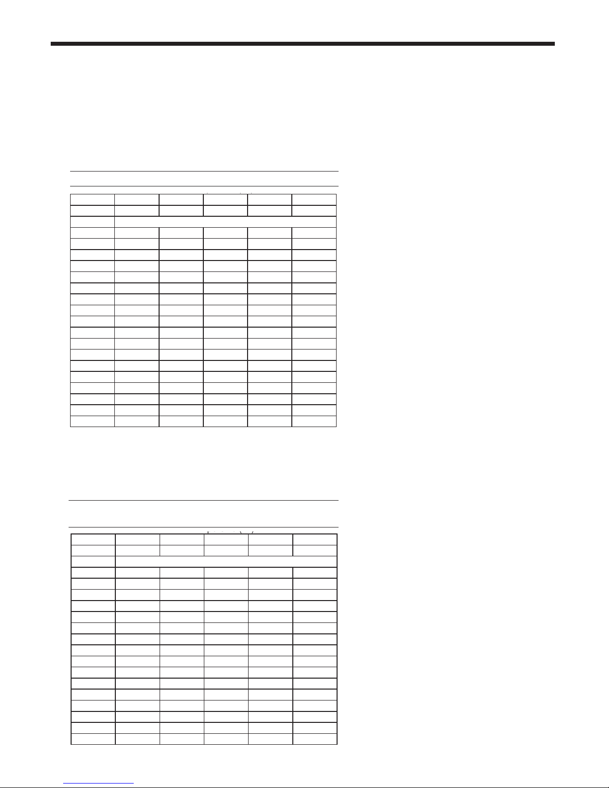
The following are gas line sizing examples from the
National Fuel Gas Code. Size your gas lines
properly, based on your installation, and all
applicable codes.
SCH 40 METAL PIPE CAPACITY FOR 0.60 SPECIFIC GRAVITY
NATURAL GAS
NOMINAL PIPE SIZE @ 0.30” W.C. PRESSURE DROP
Nominal: 2 2½ 3 4 5
Actual ID: 2.067 2.469 3.068 4.026 5.047
Length (ft)
10 4,020 6,400 11,300 23,100 41,800
20 2,760 4,400 7,780 15,900 28,700
30 2,220 3,530 6,250 12,700 23,000
40 1,900 3,020 5,350 10,900 19,700
50 1,680 2,680 4,740 9,660 17,500
60 1,520 2,430 4,290 8,760 15,800
70 1,400 2,230 3,950 8,050 14,600
80 1,300 2,080 3,670 7,490 13,600
90 1,220 1,950 3,450 7,030 12,700
100 1,160 1,840 3,260 6,640 12,000
125 1,020 1,630 2,890 5,890 10,600
150 928 1,480 2,610 5,330 9,650
175 854 1,360 2,410 4,910 8,880
200 794 1,270 2,240 4,560 8,260
150 704 1,120 1,980 4,050 7,320
300 638 1,020 1,800 3,670 6,630
350 587 935 1,650 3,370 6,100
400 546 870 1,540 3,140 5,680
Table 8. Pipe Capacity for Natural Gas
Page 17
1. Inlet pressure - Less than 2 psi
2. Pressure drop - 0.5 in w.c.
3. Specific gravity - 0.60
SCHED 40 METAL PIPE CAPACITY FOR 1.50 SPECIFIC GRAVITY
UNDILUTED PROPANE
NOMINAL PIPE SIZE @ 11” W.C. INLET AND 0.5” W.C. PRESSURE
DROP
Nominal: 1½ 2 2½ 3 4
Actual ID: 1.61 2.067 2.469 3.068 4.026
Length (ft)
10 3,520 6,790 10,800 19,100 39,000
20 2,420 4,660 7,430 13,100 26,800
30 1,940 3,750 5,970 10,600 21,500
40 1,660 3,210 5,110 9,030 18,400
50 1,480 2,840 4,530 8,000 16,300
60 1,340 2,570 4,100 7,250 14,800
80 1,230 2,370 3,770 6,670 13,600
100 1,140 2,200 3,510 6,210 124,700
125 1,070 2,070 3,290 5,820 11,900
150 1,010 1,950 3,110 5,500 11,200
175 899 1,730 2,760 4,880 9,950
200 814 1,570 2,500 4,420 9,010
250 749 1,440 2,300 4,060 8,290
300 697 1,340 2,140 3,780 7,710
350 618 1,190 1,900 3,350 6,840
400 560 1,080 1,720 3,040 6,190
Table 9. Pipe Capacity for Propane
Page 22
Page 18
Gas Pipe
Boiler Thermal
Efficiency
Boiler Combustion
Efficiency
Water
Content
Vent
Diameter
Vent
Length
Water Heater
Thermal Efficiency
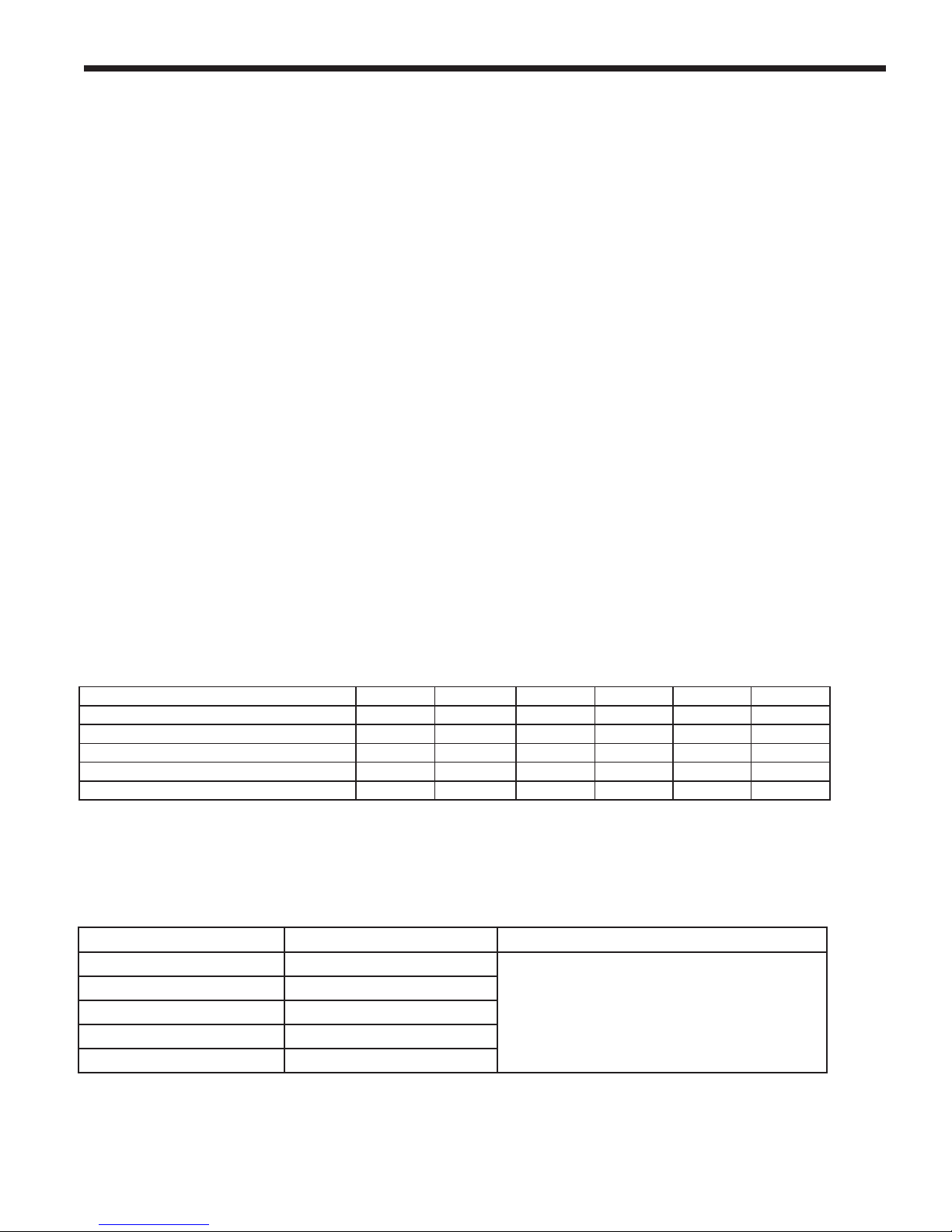
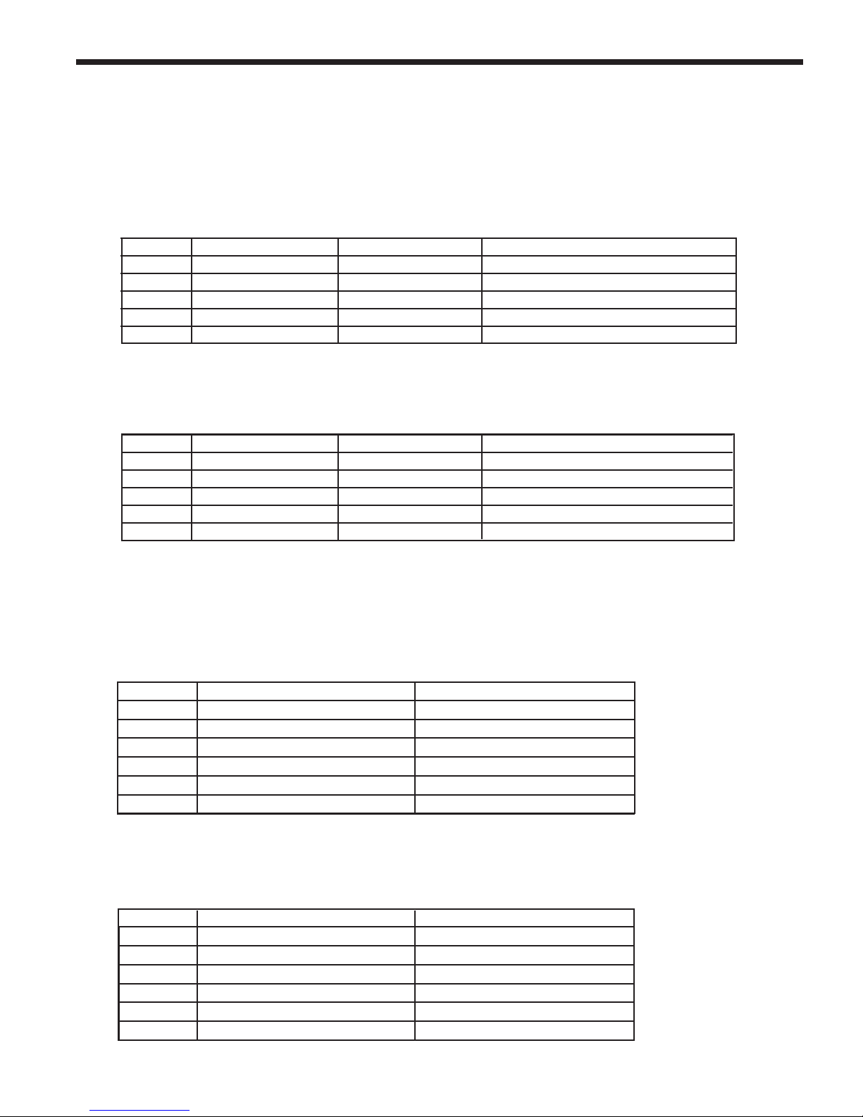
MBH kW %
1600 1600 469 96
2000 1999.0 585 96
2500 2499.0 732 96
3000 3000 878 95
3500 3500 1025 96
4000 4000 1171 96
Model
Flow
Head Loss
Flow
Head Loss
Flow
Head Loss
Flow
Head Loss
Input Rate
14°C
17°C
19°C
22°C
Output Rate
ModelModel
Dimensional Data Sizing Data
Water Pipe
Gas Pipe
Boiler Thermal
Efficiency
Boiler Combustion
Efficiency
Water
Content
Vent
Diameter
Vent
Length
Inches cm Inches cm Inches cm Inches cm (NPT) (NPT) MBH kW MBH kW % % lbs kg lbs kg lbs kg Gallons in (cm) ft (m)
2000 29.3 75 77 196 38.0 97 57.0 145 2.5 1.5 1600 1600 469 1520 445 95.0 96.0 1390 630 1562 709 1590 721 22 6 (15) 100 (30.5)
2000 29.3 75 77 196 38.0 97 57.0 145 2.5 1.5 2000 1999.9 586 1895 555 95.0 93.6 1390 630 1562 709 1590 721 22 8 (20) 100 (30.5)
2500 29.3 75 77 196 38.0 97 57.0 145 2.5 1.5 2500 2499.0 733 2374 695 95.0 93.8 1785 810 2039 925 1985 900 31 8 (20) 100 (30.5)
3000 30.8 78 87 221 41.5 105 60.5 154 3 2 3000 3000 878 2814 824 95.0 93.8 1785 810 2039 925 1985 900 31 10 (25) 100 (30.5)
3500
30.8 78 87 221 41.5 105 60.5 154 3 2 3500 3500 1025 3276 959 95.0 93.6 2278 1033 2742 1244 2478 1124 56 10 (25) 100 (30.5)
4000 34.5 88 97 246 52.0 132 70.0 178 4 2.5 4000 4000 1171 3724 1090 95.0 93.1 2278 1033 2742 1244 2478 1124 56 12 (30) 100 (30.5)
Water Heater
Thermal Efficiency
Boiler Water Flow Requirements
Model
Flow
Head Loss
Flow
Head Loss
Flow
Head Loss
Flow
Head Loss
Flow
Head Loss
GPM Feet GPM Feet GPM Feet GPM Feet LPM m LPM m LPM m LPM m
1600 122 19.4 100 14.0 87 10 76 8 1600 462 5.9 379 4.3 329 3 288 2.5
2000 150 30 128 23.5 109 17.1 95 13.6 2000 568 9.2 485 7.2 413 5.2 360 4.2
2500 190 34 158 23.6 136 17.6 119 13.6 2500 719 10.0 599 7.0 514 5.0 449 4.1
3000 226 47 190 34.2 164 25.8 142 18.9 3000 856 14.3 719 10.4 621 7.9 538 5.8
3500 266 41 222 30.6 190 23.6 166 18.6 3500 1007 12.0 839 9.0 719 7.0 629 6.0
4000 300 48 255 38.2 218 28.5
190 22.5 4000 1136 14.6 965 11.6 825 8.7 719 6.9
40°F
14°C
17°C
19°C
22°C
Model
A B C D
Temperature Rise in °C
30°F
Temperature Rise in °F
25°F
35°F
Water Flow Requirements (for water heater submittal)
Model Flow Rate Temp Rise Headloss Flow Rate Temp Rise Headloss Flow Rate Temp Rise Headloss Flow Rate Temp Rise Headloss
GPM °F Ft LPM °C m GPM °F Ft LPM °C m
1600 152 20 31.0 525 11.1 10.1 177 17 41.0 670 9.4 12. 5
2000 152 25 33.0 575 14 10.1 177 21 43.9 670 12 13.4
2500 190 25 33.7 719 13.9 10.0 220 21 46.0 833 11.7 14
3000 190 30 36.0 719 17 11.0 220 26 46.0 833 14 14
3500 222 30 30.6 839 17 9.0 266 25 40.6 1007 14 12
4000 224 34 30.0 848 19 9.1 266 29 41.2 1007 16 12.6
Allowable pH: 6.5 to 9.5
Water Hardness
1-10 grains per gallon
Water Hardness
11-15 grains per gallon
Water Hardness
11-15 grains per gallon
Water Flow Requirements (for water heater submittal)
Model Flow Rate Temp Rise Headloss Flow Rate Temp Rise Headloss Flow Rate Temp Rise Headloss Flow Rate Temp Rise Headloss
GPM °F Ft LPM °C m GPM °F Ft LPM °C m
1600 152 20 31.0 525 11.1 10.1 177 17 41.0 670 9.4 12. 5
2000 152 25 33.0 575 14 10.1 177 21 43.9 670 12 13.4
2500 190 25 33.7 719 13.9 10.0 220 21 46.0 833 11.7 14
3000 190 30 36.0 719 17 11.0 220 26 46.0 833 14 14
3500 222 30 30.6 839 17 9.0 266 25 40.6 1007 14 12
4000 224 34 30.0 848 19 9.1 266 29 41.2 1007 16 12.6
Water Hardness
1-10 grains per gallon
Water Hardness
11-15 grains per gallon
Section 5
WATER FLOW REQUIREMENTS
5.1 MagnaTech Boiler Flow and Head Requirements
B
RADFORD WHITE
Model
Headloss is for boiler only (no piping)
*
* * *
Model
Table 10. Boiler Flow and Head Requirements
5.2 MagnaTech Water Heater Flow and Head Requirements
**
*
*
Table 11. Water Heater Flow and Head Requirements
*
*
*
*
Page 23

MagnaTech
BOILERS AND VOLUME WATER HEATERS
Section 6 WATER CONNECTIONS
BMGH BOILERS
6.1 BMGH System Piping:
Hot Supply Connections
Note -This appliance must be installed in a closed
pressure system with a minimum of 12 psi (82.7
kPa) static pressure at the boiler.
The hot water piping should be supported
by suitable hangers or oor stands. Do not
support the piping with this appliance. The
hangers used should allow for expansion and
contraction of pipe. Rigid hangers may transmit
noise through the system resulting from the
piping sliding in the hangers. We recommend
that padding be used when rigid hangers are
installed. Maintain 1” (2.5 cm) clearance to
combustibles for all hot water pipes.
Pipe the discharge of the relief valve (full size)
to a drain or in a manner to prevent injury in the
event of pressure relief. Install an air purger,
an air vent, an expansion tank, a hydronic ow
check valve in the system supply loop, and
any other devices required by local codes. The
minimum ll pressure must be 12 psig (82.7
kPa). Install shutoff valves where required by
code.
Suggested piping diagrams are shown in Figure
7 through Figure 10. These diagrams are meant
only as guides. Components required by local
codes must be properly installed.
TheMagnaTech’sefciencyishigherwith
lower return water temperatures. Therefore,
to get the best low return temperature with
multiple boilers, pipe as shown in Figure 9 and
Figure 10.
6.2 BMGH Cold Water Make-Up
1. Connect the cold water supply to the inlet
connection of an automatic ll valve.
2. Install a suitable back ow preventer
between the automatic ll valve and the
cold water supply.
3. Install shut off valves where required.
Page 19
be equipped with ow control valves or other
automatic means to prevent gravity circulation
of the boiler water during the cooling cycle.
A boiler installed above radiation level, or as
required by the authority having jurisdiction,
must be provided with a low water cutoff device
either as a part of the boiler or at the time of
boiler installation.
6.3 BMGH Freeze Protection
MagnaTech units may be installed indoors
or outdoors. If installing outdoors in a location
that may experience freezing temperatures,
precautions must be taken to prevent water in
the heat exchanger and condensate inside and
outside of the boiler from freezing. Damage due
to freezing water or condensate is not covered by
the warranty.
If installed indoors, and there is an event such
as a power outage, interruption of gas supply,
failure of system components, activation of
safety devices, etc., this may prevent a boiler
from ring. Any time a boiler is subjected
to freezing conditions, and the boiler is not
abletore,and/orthewaterisnotableto
circulate, there is a risk of freezing in the
boiler or in the pipes in the system. When
water freezes, it expands. This may result
in bursting of pipes, or damage to the boiler,
and this could result in leaking or ooding
conditions.
Do not use automotive antifreeze. To help
prevent freezing, Bradford White recommends
the use of inhibited glycol concentrations
between 20% and 35% glycol. Typically, this
concentration will serve as burst protection
for temperatures down to approximately -5°F
(-20°C). If temperatures are expected to be
lower than -5°F (-20°C), glycol concentrations
up to 50% can be used. When concentrations
greaterthan35%areused,waterowrates
must be increased to maintain a 20°F to 25°F
temperature rise through the boiler.
In some installations, a hot water heating
boiler is connected to heating coils located in
an air handling appliance where the coils may
be exposed to refrigerated air circulation. In
these cases, the boiler piping system must
Page 24
Page 20
B
RADFORD WHITE
WARNING
Glycol must not be used in domestic hot
water applications. Refer to Section 7 for
instructions on freeze protection for BMGV
units (domestic hot water).
Different glycol products may provide varying
degrees of protection. Glycol products must
be maintained properly in a heating system,
or they may become ineffective. Consult the
glycol specications, or the glycol manufacturer,
for information about specic products,
maintenance of solutions, and set up according
to your particular conditions.
The following manufacturers offer glycols,
inhibitors, and anti foamants that are suitable
for use in the MagnaTech. Please refer to the
manufacturers instructions for proper selection
and application.
• Sentinel Performance Solutions Group
• Hercules Chemical Company
• Dow Chemical Company
The boiler control offers some assistance
with freeze protection, as long as the boiler is
energized, and able to re.
1. If the outlet sensor detects less than 45°F,
the control energizes the boiler pump.
2. If the outlet sensor detects less than 35°F,
the control will re at low rate.
3. Once in freeze protect mode, the boiler will
remain in that state until the outlet sensor
detects greater than 50°F.
A condensate drain trap is included with the
MagnaTech and is designed to drain the boiler
of condensate. The vent condensate should
be drained through a drain tee located in the
vent line. This will help prevent excessive
condensate from entering the boiler condensate
trap.
Connect a 3/4” PVC pipe between the drain
connection and a oor drain (or condensate
pump if a oor drain is not accessible).
The condensate drain must be installed to
prevent the accumulation of condensate.
When a condensate pump is not used, the
tubing must continuously slope downward
toward the drain with no spiraling.
Consult local codes for the disposal method.
Caution
Condensate is mildly acidic (pH=5), and
may harm some oor drains and/or pipes,
particularly those that are metal. Ensure
that the drain, drainpipe, and anything that
will come in contact with the condensate
can withstand the acidity, or neutralize
the condensate before disposal. Damage
caused by failure to install a neutralizer
kit or to adequately treat condensate will
not be the manufacturer’s responsibility.
6.4 BMGH Suggested Piping
Schematics
Figure 7 through Figure 10 show suggested
piping congurations for BMGH boilers.
These diagrams are only meant as guides. All
components or piping required by local code
must be installed.
6.5 Condensate Drain Trap
Page 25
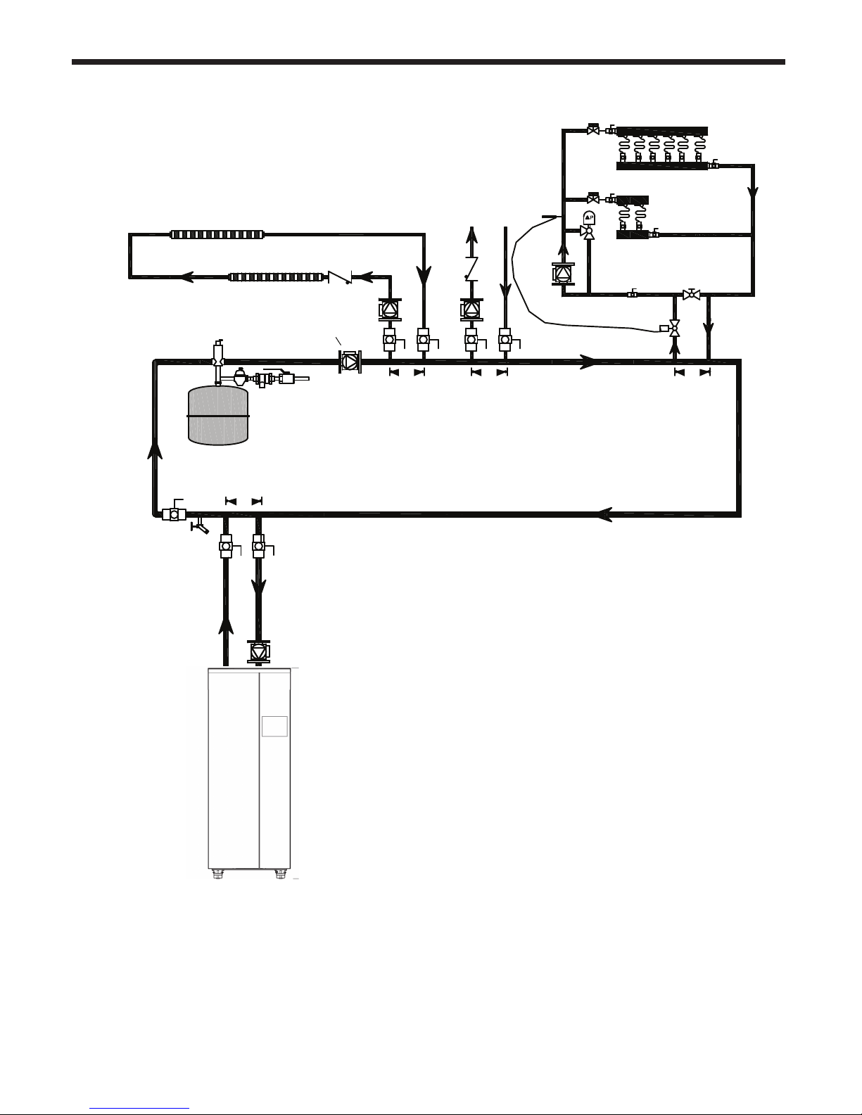
MagnaTech
BOILERS AND VOLUME WATER HEATERS
Space heating zone circuits
Space heating zone circuit
Page 21
Low temp. radiant zone
Air vent
Water feed
controls
4 pipe dia. max.
System pump
4 pipe dia. max. 4 pipe dia. max. 4 pipe dia. max.
Note This drawing is a schematic
representation of a piping style,
and is not intended to be used
as a working installation drawing.
Local code requirements
must be met.
Figure 7. Hydronic Piping — Single Boiler, Multiple Temperature Zones
Zoning with circulators
Page 26
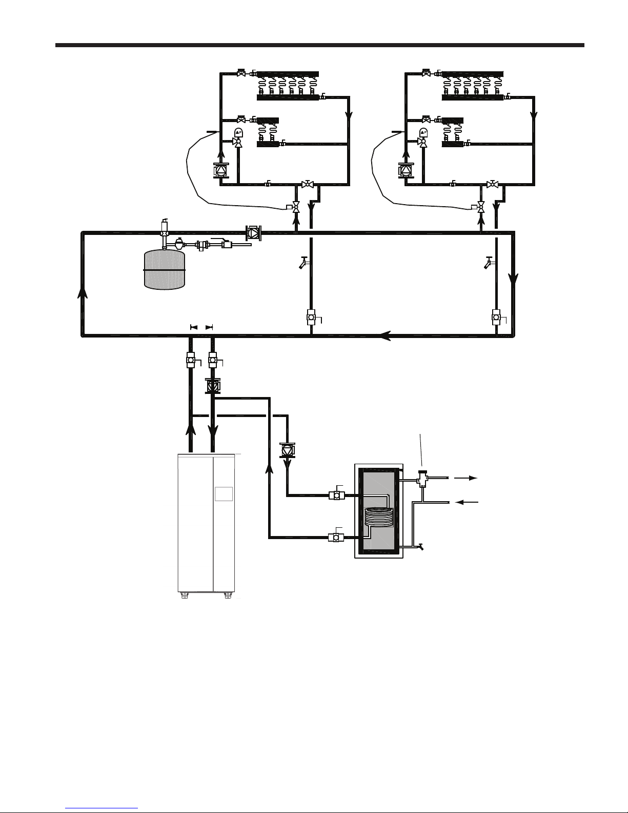
Page 22
Note This drawing is a schematic
representation of a piping style,
and is not intended to be used
as a working installation drawing.
Local code requirements
must be met.
B
RADFORD WHITE
Air vent
Expansion tank
4 pipe dia. max.
Low temp. radiant zone
Water feed controls
Indirect DHW tank
Low temp. radiant zone
Anti-scald
mixing
valve
Domestic
hot water
out
Figure 8. Hydronic Piping — Single Boiler with Low Temperature Zones and Indirect DHW Tank
Indirect tank directly off of boiler
Cold water
Page 27
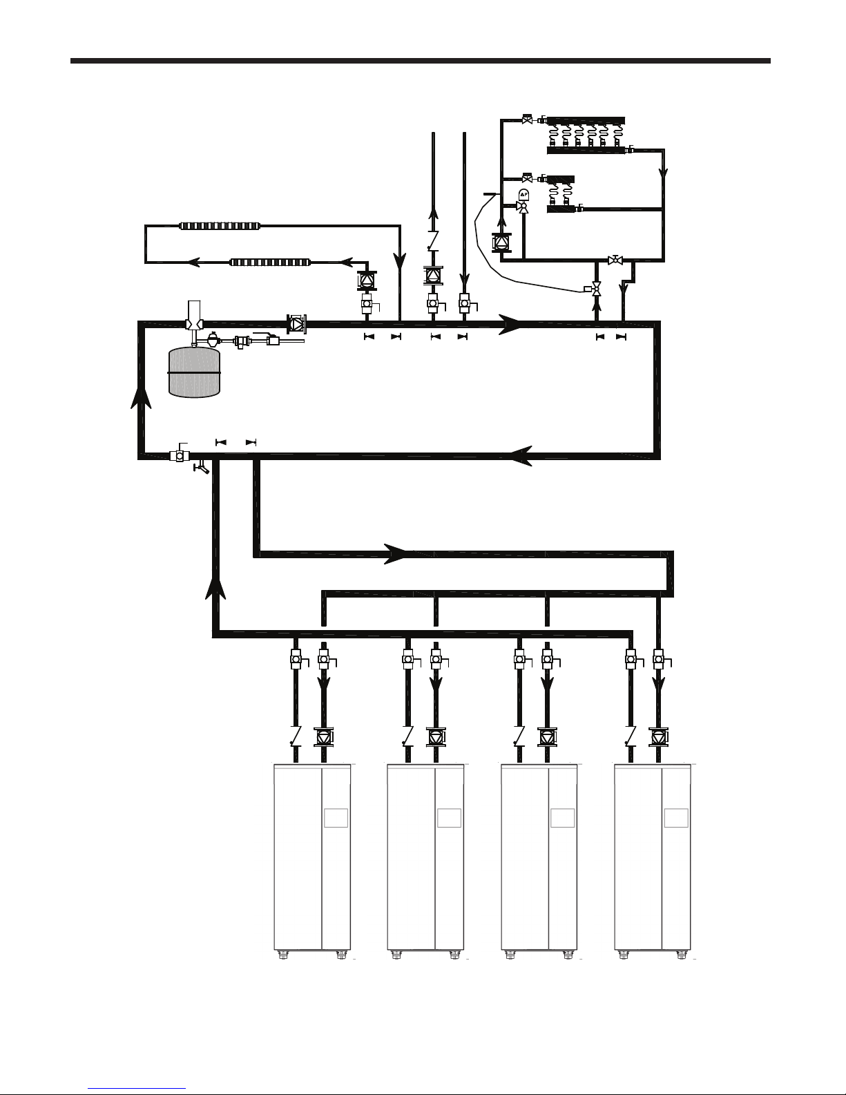
MagnaTech
BOILERS AND VOLUME WATER HEATERS
Page 23
Note This drawing is a schematic
representation of a piping style,
and is not intended to be used
as a working installation drawing.
Local code requirements
must be met.
Space heating zone circuit
Air vent
Water feed controls
Expansion tank
4 pipe dia. max.
Space heating
zone circuits
Low temp. radiant zone
4 pipe dia. max. 4 pipe dia. max.
Common piping must be sized for the
combined water ow of all of the boilers.
Figure 9. Hydronic Piping — Multiple Boilers, Multiple Temperature Zones, Reverse Return.
Zoning with circulators
Page 28
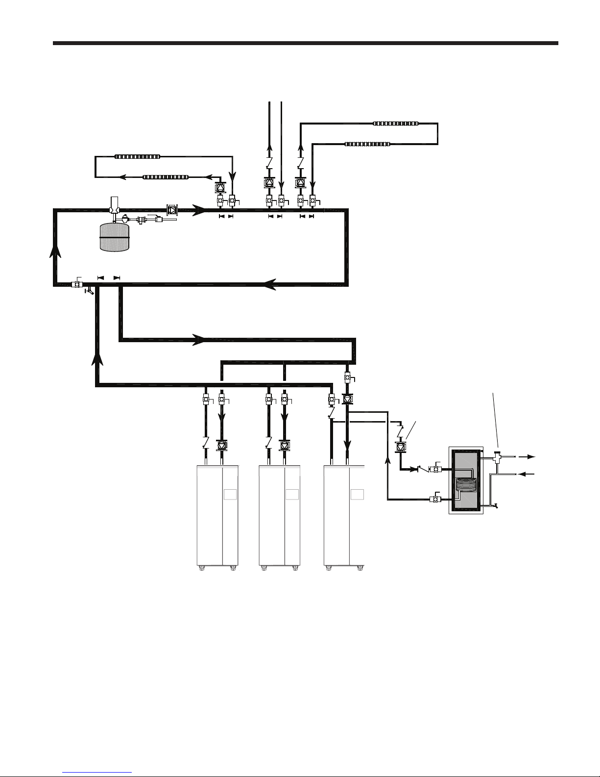
Page 24
Space heating zone circuit
Air vent
Space heating zone circuits
High temp. space heating zone circuit
B
RADFORD WHITE
Water feed
controls
Expansion tank
4 pipe dia. max.
Common piping must be sized for the
combined water ow of all the boilers.
Note This drawing is a schematic
representation of a piping style,
and is not intended to be used
as a working installation drawing.
Local code requirements
must be met.
4 pipe dia. max. 4 pipe dia. max.
Note Indirect pump
must be sized
for boiler and
indirect
Indirect
DHW tank
Anti-scald
mixing valve
Domestic
hot water
out
Cold
water
Figure 10. Hydronic Piping — Multiple Boilers, Indirect DHW Off of One Boiler
Note In this piping arrangement,
the boiler pump must turn o
during DHW operation.
Page 29
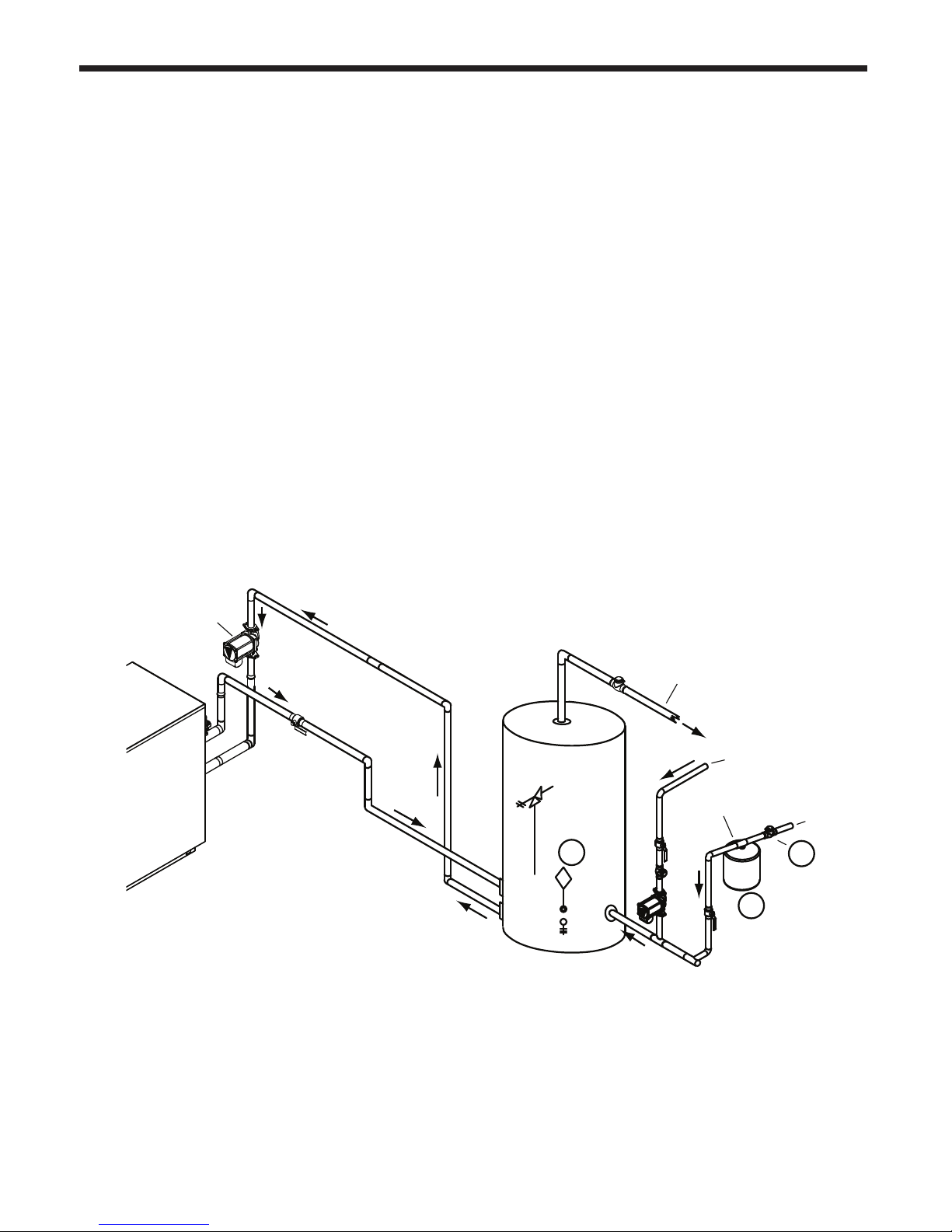
MagnaTech
BOILERS AND VOLUME WATER HEATERS
Section 7 WATER CONNECTIONS
BMGV UNITS
7.1 BMGV Water Quality
BMGV water heaters must be installed in water
conditions of 15 gpg hardness or less, with a
pH range of 6.5 to 9.5 pH. Values outside of
this range may reduce the life expectancy of
the product. Operating the BMGV in water
with higher hardness levels will cause heat
exchanger fouling, erosion, or corrosion, leading
to premature component failure, reduced
efciency, heat exchanger failure or system
failure. Failure of this type will not be warranted.
If the water in use exceeds the conditions
recommended, water softeners or other devices
should be installed to improve water quality.
Page 25
7.2 BMGV Suggested Piping
Schematics
Figure 11 through Figure 13 show suggested
piping congurations for BMGV boilers.
These diagrams are only meant as guides. All
components or piping required by local code
must be installed.
7.3 BMGV Piping Requirements
The water piping should be supported by
suitable hangers and oor stands. Do not
support the piping with this appliance. The
hangers used should allow for expansion and
contraction of copper pipe. Rigid hangers
may transmit noise through the system
resulting from piping sliding in the hangers.
We recommend that padding be used when
NOTE: This drawing shows
Location
of pump
TPRV
NOTES:
1. Locate BMGV DHW sensor or remote aquastat well
in lower 1/3 of tank.
2. Back ow preventer may be required - check local codes.
3. Thermal expansion tank may be required - check local codes.
4. Caution: Pump sizing must be based upon water hardness at job site.
5. If the tank does not have a tapping for the cold water supply, the supply may be run
to the pipe between the tank and boiler inlet.
suggested piping conguration and
valving. Check with local codes and
ordinances for additional requirements.
1
Supply
Building
return
Expansion
tank
3
Cold
water
supply
2
Figure 11. DHW Piping - One Heater, One Vertical Tank
Page 30

Page 26
B
RADFORD WHITE
rigid hangers are installed. Maintain 1” (2.5 cm)
clearance to combustibles for hot water pipes.
Pipe the discharge of the relief valve (full size)
to the drain or in a manner to prevent injury in
the event of pressure relief. Install a diaphragm-
type expansion tank, ow check, and shutoff
valves where needed or as required by code.
The piping should be installed so that each
pump supplies ow only to the heater to which it
is attached.
7.4 BMGV Cold Water Make-Up
The cold water make-up may be connected to
the tank as shown in Figure 11 through Figure
13. If the tank does not have a tapping for the
cold water supply, the supply may be run to
2
Cold water
supply
the pipe between the tank and boiler inlet.
Install back-ow preventers and shut-offs
where needed or required by code.
7.5 BMGV Freeze Protection
If installing outdoors in a location that may
experience freezing temperatures, precautions
must be taken to prevent water in the heat
exchanger and condensate inside and outside
of the boiler from freezing. Damage due to
freezing water or condensate is not covered
by the warranty.
If installed indoors, and there is an event
NOTES:
1. Locate the BMGV DHW sensor or remote aquastat well
in lower 1/3 of tank.
2. Back ow preventer may be required - check local
codes.
3. Thermal expansion tank may be required check local codes.
4.
Caution: Pump sizing must be based upon water
Building
return
hardness at job site.
5. If the tank does not have a tapping for the cold water
supply, the supply may be run to the pipe between the
tank and boiler inlet.
Pump
Supply
Expansion
tank
TPRV
1
Ball valve
(typical)
TPRV
1
Figure 12. DHW Piping - One Heater, Two Vertical Tanks
NOTE: This drawing shows
suggested piping conguration and
valving. Check with local codes and
ordinances for additional requirements.
Page 31

MagnaTech
NOTES:
1. Locate the BMGV DHW sensor
or remote aquastat well
in lower 1/3 of tank.
2. Back ow preventer may be
required - check local codes.
3. Thermal expansion tank may be
required - check local codes.
4.
Caution: Pump sizing must
be based upon water
hardness at job site.
5. If the tank does not have a tapping for
the cold water supply, the supply may
be run to the pipe between the tank
and boiler inlet.
6. Common piping must be sized for
the combined water ow of all the
heaters.
BOILERS AND VOLUME WATER HEATERS
Cold water
supply
3
Expansion
tank
Page 27
Building
return
2
NOTE: This drawing shows
suggested piping conguration and
valving. Check with local codes and
ordinances for additional requirements.
Supply
TPRV
Ball valve
(typical)
Pump
TPRV
Check valve
Pump
Check valve
Figure 13. DHW Piping - Two Heaters, Two Vertical Tanks
such as a power outage, component failure or
other issue when freezing is likely, the heater
and system must be drained to avoid the risk
of damage due to freezing. Glycol must not be
used in volume water heating applications.
7.6 BMGV Water Flow
See Section 5 for water ow and head
requirements.
Note - The head loss for the piping, ttings, and
7.7 Condensate Drain Trap
A condensate drain trap is included with the
MagnaTech and is designed to drain the boiler
of condensate. The vent condensate should be
drained through a drain tee located in the vent
line. This will help prevent excessive condensate
from entering the boiler condensate trap.
Connect a 3/4” PVC pipe between the drain
connection and a oor drain (or condensate
pump if a oor drain is not accessible).
1
The condensate drain must be installed to
prevent the accumulation of condensate.
When a condensate pump is not used, the
tubing must continuously slope downward
toward the drain with no spiraling.
Consult local codes for the disposal method.
Caution
Condensate is mildly acidic (pH=5), and
may harm some oor drains and/or pipes,
particularly those that are metal. Ensure
that the drain, drainpipe, and anything that
will come in contact with the condensate
can withstand the acidity, or neutralize
the condensate before disposal. Damage
caused by failure to install a neutralizer
kit or to adequately treat condensate will
not be the manufacturer’s responsibility.
Page 32

Page 28
Section 8
ELECTRICAL CONNECTIONS
8.1 Installation Warnings
B
RADFORD WHITE
WARNING
The appliance must be electrically grounded in
accordance with the requirements of the authority
having jurisdiction or, in the absence of such
requirements, with the latest edition of the National
Electrical Code, ANSI/NFPA 70, in the U.S. and
with the latest edition of CSA C22.1 Canadian
Electrical Code, Part 1, in Canada. Do not rely
on the gas or water piping to ground the metal
parts of the boiler. Plastic pipe or dielectric unions
may isolate the boiler electrically. Service and
maintenance personnel, who work on or around
the boiler, may be standing on wet oors and
could be electrocuted by an ungrounded boiler.
Electrocution can result in severe injury or death.
Single pole switches, including those of safety
controls and protective devices, must not be wired
in a grounded line.
All electrical connections are made on the terminal
blocks that are located inside the control panel.
Wiring connections are shown in Figure 34.
CAUTION
The supply voltage to the MagnaTech unit
must not be disconnected, except for service
or isolation, or unless otherwise instructed by
procedures outlined in this manual. To signal
a call for heat, use the 24V eld interlock, as
shown in the wiring diagram.
DO NOT MAKE AND BREAK THE LINE
VOLTAGE TO THE MagnaTech UNIT TO
SIGNAL A CALL FOR HEAT. A call for heat/
end call for heat MUST be connected to the
eld interlock terminals. Some MagnaTech
components are designed to have constant
voltage during normal operation. If the
MagnaTech’s supply voltage is toggled as a
call for heat signal, premature failure of these
components may result.
The MagnaTech unit does not recognize 4mA
as a signal to shut off. If the call for heat is not
connected between the eld interlock terminals,
the MagnaTech will remain in low re when it
sees 4mA as a modulating signal.
All internal electrical components have been
prewired. No attempt should be made to connect
electrical wires to any other location except the
terminal blocks.
8.2 Main Power Connections
MagnaTech is provided with an electrical junction
box in the rear panel for easy connections and all
wires are factory installed between this junction box
and the Main High Voltage Box. The MagnaTech
line is equipped with multiple voltage packages to
adapt to customer needs ranging from 120-600 volts
with single or 3 phase versions. Refer to the rating
plate for appropriate voltage and current ratings. As
a common industry practice, Bradford White has
color coded the single and three phase wires.
Three Phase Single Phase
600 480 208 120 240
L1 P BR Blk L1 Blk Blk
L2 V O R L2 Wht R
L3 T Y BL
Table 12. PhaseVoltageColorIdentication
On three phase models a step down transformer
(which is protected using an appropriate din rail
mounted circuit breaker) generates 120 volt single
phase to power the 24 Volt Transformer. The 120
volt and 24 volt outputs of either transformer are
protected with resettable fuses mounted in the top
of the high voltage box. The 24 volt transformer is
also redundantly protected by its integrated 4 amp
resettable fuse.
Page 33

MagnaTech
Model 1600 2000
Voltage
Nominal
Current
FLA
BOILERS AND VOLUME WATER HEATERS
120 220
8.1 3.6 N/A N/A N/A 15.1 8.8 7.0 3.2 2.8
17.7 9.7 N/A N/A N/A 22.6 11.3 12.7 6.2 4.5
ø 480 3ø 600 3ø
208 3
120 220
208 3
ø 480 3ø 600 3ø
Table 14. Electrical Data
Model 2500 / 3000 3500 / 4000
Voltage
Nominal
Current
FLA
120 220
N/A N/A 12.5 5.0 4.0 N/A N/A 113 4.8 4.4
N/A N/A 19.4 8.7 5.9 N/A N/A 19.4 8.7 5.9
208 3
ø 480 3ø
600 3ø 120 220
208 3
Table 13. Electrical Data
Page 29
ø 480 3ø 600 3ø
On single phase models, the incoming voltage will
be protected by the appropriate circuit breaker sized
and installed, by a qualied Electrician/authorized
personnel. The 120 volt and 24 volt systems will be
protected with resettable fuses mounted in the top
of the high voltage box. The 24 volt transformer is
also redundantly protected by its integrated 4 amp
resettable fuse.
8.3 Pump Connections and Operation
The controller in the MagnaTech energizes the
appropriate pump contacts when it receives a call for
heat. Once the call for heat is satised, the pumps
will remain on for the dened pump overrun time.
The Boiler, System, and DHW pump terminals
are found on the Main control board TB1-15A
through 20A. They are fed 120 Volts internally
from the main power feed. The current rating
of the contacts is 7.4 amps, and an appropriately
sized contactor must be supplied and installed
by a qualied technician to ensure proper pump
operation. Once the system has been installed, the
“Pump Conguration” menu will allow the installer
to adjust Pump control, Overrun time and Demand
control for the various pumps in the system.
Caution
Label all wires prior to disconnection when
servicing controls. Wiring errors can cause
improper and dangerous operation. Verify
proper operation after operation servicing.
Attention
Au moment de l’entretien des commandes,
étiquetez tous les ls avant de les
débrancher. Les erreurs de câblage
peuvent nuire au bon fonctionnement et
être dangereuses. S’assurer que l’appareil
fonctionne adéquatement une fois l’entretien
terminé.
Caution
The supply voltage to the MagnaTech must
not be disengaged, except for service or
isolation, or unless otherwise instructed by
procedures outlined in this manual. To signal
a call for heat, use the correct terminals as
instructed in Section 8.
Page 34

Page 30
VARI-PRIME PRINTED CIRCUIT BOARD KIT
9
AUTO-RESET HIGH LIMIT CONTROL
8
TOUCH SCREEN
ALARM SILENCE SWITCH
MANUAL RESET HIGH LIMIT
ALARM BELL (optional)
LOW WATER CUT-OFF
BAS GATEWAY (optional)
7
6
5
4
Terminal block for field connections
3
2
1
DESCRIPTION
ITEM NO.
PARTS LIST
1
CA0099
VARI-PRIME PRINTED CIRCUIT BOARD KIT
2
KM004400
AUTO-RESET HIGH LIMIT CONTROL
1
E2339800
ALARM SILENCE SWITCH
MANUAL RESET HIGH LIMIT
ALARM BELL (optional)
LOW WATER CUT-OFF
BAS GATEWAY (optional)
1
E2346100
1
KM004300
1
A0014300
Terminal block for field connections
A0014300
1
E0086800
1
30N7050
QTY
PART NO.
5
2
4
6
8
1
9
7
3
8.4 Control Panel Layout
B
RADFORD WHITE
Figure 14. Electronics Panel Layout
VARIABLE SPEED PUMP CONTROL PCB KIT
Page 35

MagnaTech
BOILERS AND VOLUME WATER HEATERS
Page 31
Page 36

Page 32
TT
TT
ALARM
ALARM
DHW SENSOR
REMOTE RESET
4-20mA (-)
0-110VDC (-)
0-10VDC (+)
OUTDOOR/
SYSTEM
ANALOG (-)
ANALOG (+)
0-10V
PUMP
OUTDOOR/
SYSTEM
TOD
DHW SENSOR
COM2-A
COM2-B
COM2-C
MB2-A
MB2-B
MB2-C
REMOTE/TOD
COMMON
4-20ma (+)
24V NEUTRAL
GROUND
24V +
SYSTEM PUMP
DHW PUMP
DHW PUMP
TB1
120V (N)
120V +
BOILER PUMP
SYSTEM PUMP
120V +
A
120V (N)
BOILER PUMP
24V NEUTRAL
24V NEUTRAL
24V +
24V +
120V (N)
87
CR1
3
(+)
(-)
12
24VAC POWER
VTB1
43 2
1
8
C
NONC
9
15
12
13
414
LOW GAS
J10-5
J10-6
J10-4
J10-2
J10-3
J10-1
J3-MB2C
J3-MB2B
J3-MB2A
DISPLAY #6
DISPLAY #5
DISPLAY #4
GND
BL
BK
W/V
BK/R
MAIN PWR
SWITCH
BK/OR
WBK
GROUND
24V+
24V-
120V NEUT
120V LOAD
120V LINE
312 45
6
BR/V
BR/G
BL/Y
BR/R
5
BK/W
G
TOD
1
2
8
3
FROM LWCO
"PROBE" TO PROBE
TO LWCO PROBE AT HX
Y
BL
OR
OR/W
BR/Y
BL/W
BR
BL
BK
W
G
W
BK
BK
BK/R
BK/Y
BK/Y
G
BK
W/V
W/R
BR
W/R
W/R
GY/BL
BR/R
BR/Y
GY/V
BL
W/R
W/R
W
Y
4
DISPLAY #7
DISPLAY #8
LWCO #2 120V (N)
GY/BK
R
GY/R
P1 P2
ADDITIONAL
HIGH LIMIT
BLOCKED FLUE &
BLOCKED INTAKE
THERMAL
CUTOUT
FLOW SWITCH
HIGH GAS
MANUAL RESET
HIGH LIMIT
TO TB1-4C (120V N)
TO B4 (PROBE)
2
1
9
2
10
3
11
4
12
5
13
6
14
7
15
PILOT
VALVE
MAIN
VALVE
1
2
3
4
5
6
7
8
9
10
11
12
13
14
15
16
17
18
19
20
21
22
23
24
25
26
27
28
29
30
31
32
33
34
35
36
37
38
39
40
41
42
43
44
45
7
9
10
LWCO
BK
G
W/G
W/R
W
W
12 POS CONN "B"
16 POS CONN "A"
PROBE
BC
BK/OR
Y
BR/R
Y/R
BR/G
W/G
Y/G
6 POS CONN "E"
8
R/BN
R/BK
R/BR
V
V/W
V/BK
Y
W
BK
BR/R
BK
BR/G
BK/O
BR/V
BK/V
BL/W
W/R
BL
BL
WIRE VOLTAGE KEY
24V=
120V=
CONDENSATE
*
BL
BL
Y
SPARK
GENERATOR
IGNITOR
BY LAARS HEATING SYSTEMS CO.
DISCLOSED TO OTHERS FOR MANUFACTURING OR ANY OTHER
REPRODUCED, TRANSFERRED TO OTHER DO CUMENTS, USED OR
8
5
7
6
PURPOSE EXCEPT AS SPECIFICALLY A UTHORIZED IN WRITING
4
PROPRIETARY TO LAARS HEATING SYSTEMS CO. AND SHALL NOT BE
THIS DOCUMENT AND THE INFORMATION CONTAINE D HEREIN ARE
WIRE COLOR LEGEND
BK BLACK
BL BLUE
BR BROWN
G GREEN
GY GRAY
OR ORANGE
R RED
V VIOL ET
W WHITE
Y YELLOW
B
RADFORD WHITE
8.5 Wiring Diagrams
Figure 15. Wiring Diagram, BMGT 1600
Page 1 of 2
Page 37

MagnaTech
T
B
1
3
3
C
T
B
1
3
4
C
T
B
1
3
5
C
CONNECTOR
"D"
COM 1 COM2
Y
BL
1 2 3 4 5 6 7 8
T
B
1
1
0
C
2
4
V
(
)
T
B
1
-
1
4
C
2
4
V
(
+
)
DISPLAY
POWER
MB1 MB2 ECOM
RESET
ALARM
FLAME
J11
J10
J9
J8
J2
J1
J7
J6
J5
J4
A B C A B C 1 2 3
1
2
3
4
5
6
7
8
1
2
3
4
5
6
7
1
2
3
4
5
6
7
1
2
3
4
5
6
7
8
9
10
11
12
8
7
6
5
4
3
2
1
7
6
5
4
3
2
1
7
6
5
4
3
2
1
12
11
10
9
8
7
6
5
4
3
2
1
87
65
CR1
4
3
21
87
65
CR2
4
3
21
432 1
VTB3
1
2
3
4
VTB6
1
2
3
(+)
(-)
12
43
21
0-10 V(-)
4-20ma(-)
4-20ma(+)
0-10 V(+)
ENCLOSURE
(OPTIONAL)
N/O
N/C
COM
P/N LAARS-1
DIGITIZED
VARIPRIME
24VAC POWER
VTB1
VTB4VTB5VTB2
43 2
1
2
1
2
1
2
1
3
STACK TEMP
OUTLET WATER TEMP
INLET WATER TEMP
8 POS CONN "C"
6
8
7
2
5
4
3
1
241
324
1
W/R
W/G
W/R
BL
BL/W
OUTLET TEMP
INLET TEMP
DRAIN WIRE
FROM
SHIELDED
CABLE
BL
Y
BL
V/W
V
OR
OR/W
W/BK
W/V
W/BK
BR/Y
BR/Y
G
W
BK
BK
BK/R
BK/Y
W/R
W/R
W/R
GY/BL
BR/R
BR/Y
GY/V
GY/BK
R
GY/R
FLAME ROD
BK/OR
21
34
TB1-39C
TB1-40C
TB1-42C
TB1-43C
TB1-45C
TB1-44C
J3
Y
W
BR
BK
BR/R
BK
BR/G
BK/O
BR/V
BK/V
TB1-36C
TB1-37C
TB1-38C
NOTE:
DASHED LINES DENOTE VARIPRIME PUMP 1.
CONTROLS. VARIPRIME INSTALLED ON
HYDRONIC UNITS ONLY.
BL
BL
W
WBK
BL
BL
V
V
R
R
BLBL Y Y
BL
Y
1
2
3
4
5
BLOWER
CONTROL
CONNECTOR
DECIMALS .XXX
D
W
G
N
O
.
SHEET 1 OF 1
D
DWG. NO:SOFTWARE
INTENDED SIZE:
D
C
B
TOLERANCES ARE:
DECIMALS .X
.03
AL 1/22/15
S
JAT 1/ 22/15
FRACTIONS
32
A
ECN
DRAFT
1
N/A
1
A
AL 7/2/15
MATERIAL:
1
.1
DRAFT
DIMENSIONS ARE IN INCHES.
UNLESS OTHERWISE SPECIFIED:
REVISIONS
APPROVALS
DECIMALS .XX
REV.
.010
E23629
A
REV.
CHANGE:
DIAGRAM, WIRING/BLOCK, MGT 1.6
IGNITOR
TITLE:
15-099N
APPR
ENGR
JAB 7/2/15
1/8"
4
N/A
S
H
R
E
V
E
2
3
6
2
9
APPR
ENGR APPR
REMOVED HSI AND ADDED SPARK GENERAT OR AND
CHECK
FINISH
ANGLES
DO NOT SCALE DRAWING.
THIRD ANGLE PROJECTION.
SCALE: NONE
BOILERS AND VOLUME WATER HEATERS
Page 33
1. DASHED LINES DENOTE VARIABLE SPEED
PUMP CONTROLS, WHICH IS INSTALLED ONLY
ON HYDRONIC UNITS
Page 2 of 2
Page 38

Page 34
TT
TT
ALARM
ALARM
DHW SENSOR
REMOTE RESET
4-20mA (-)
0-110VDC (-)
0-10VDC (+)
OUTDOOR/
SYSTEM
ANALOG (-)
ANALOG (+)
0-10V
PUMP
OUTDOOR/
SYSTEM
TOD
DHW SENSOR
COM2-A
COM2-B
COM2-C
MB2-A
MB2-B
MB2-C
REMOTE/TOD
COMMON
4-20ma (+)
24V NEUTRAL
GROUND
24V +
SYSTEM PUMP
DHW PUMP
DHW PUMP
TB1
120V (N)
120V +
BOILER PUMP
SYSTEM PUMP
120V +
A
120V (N)
BOILER PUMP
24V NEUTRAL
24V NEUTRAL
24V +
24V +
120V (N)
87
CR1
3
(+)
(-)
12
24VAC POWER
VTB1
43 2
1
8
C
NONC
9
15
12
13
414
IGNITOR
Y
BL
BL
BK W
*
GY/R
GY/BL
*
VFD
5216
17
CONDENSATE
24V=
120V=
14 kV=
WIRE VOLTAGE KEY
BL
BL
W/R
BL/W
BK/V
BR/V
BK/O
BR/G
BK
BR/R
BK
W
Y
V/BK
V/W
V
R/BR
R/BK
R/BN
8
6 POS CONN "E"
Y/G
W/G
BR/G
Y/R
BR/R
Y
BK/OR
CB
PROBE
16 POS CONN "A"
12 POS CONN "B"
W
W
W/R
W/G
G
BK
LWCO
10
9
7
1
2
3
4
5
6
7
8
9
10
11
12
13
14
15
16
17
18
19
20
21
22
23
24
25
26
27
28
29
30
31
32
33
34
35
36
37
38
39
40
41
42
43
44
45
MAIN
VALVE
PILOT
VALVE
SPARK
GENERATOR
15
7
14
6
13
5
12
4
11
3
10
2
9
1
2
TO B4 (PROBE)
TO TB1-4C (120V N)
MANUAL RESET
HIGH LIMIT
HIGH GAS
FLOW SWITCH
THERMAL
CUTOUT
BLOCKED FLUE &
BLOCKED INTAKE
ADDITIONAL
HIGH LIMIT
P1 P2
GY/R
R
GY/BK
LWCO #2 120V (N)
DISPLAY #8
DISPLAY #7
4
Y
W
W/R
W/R
BL
GY/V
BR/Y
BR/R
GY/BL
W/R
W/R
BR
W/R
W/V
BK
G
BK/Y
BK/Y
BK/R
BK
BK
W
G
W
BK
BL
BR
BL/W
BR/Y
OR/W
OR
BL
Y
TO LWCO PROBE AT HX
FROM LWCO
"PROBE" TO PROBE
3
8
2
1
TOD
G
BK/W
5
BR/R
BL/Y
BR/G
BR/V
6
54213
120V LINE
120V LOAD
120V NEUT
24V-
24V+
GROUND
BK W
BK/OR
MAIN PWR
SWITCH
BK/R
W/V
BK
BL
GND
DISPLAY #4
DISPLAY #5
DISPLAY #6
J3-MB2A
J3-MB2B
J3-MB2C
J10-1
J10-3
J10-2
J10-4
J10-6
J10-5
LOW GAS
W
BK
8
7
6
5
4
BY LAARS HEATING SYSTEMS CO.
PURPOSE EXCEPT AS SPECIFICALLY A UTHORIZED IN WRITING
REPRODUCED, TRANSFERRED TO OTHER DO CUMENTS, USED OR
DISCLOSED TO OTHERS FOR MANUFACTURING OR ANY OTHER
PROPRIETARY TO LAARS HEATING SYSTEMS CO. AND SHALL NOT BE
THIS DOCUMENT AND THE INFORMATION CONTAINE D HEREIN ARE
WIRE COLOR LEGEND
BK BLACK
BL BLUE
BR BROWN
G GREEN
GY GRAY
OR ORANGE
R RED
V VIOL ET
W WHITE
Y YELLOW
B
RADFORD WHITE
Figure 16. Wiring Diagram, BMGT 2000 thru BMGT 4000
Page 1 of 2
Page 39

MagnaTech
T
B
1
3
3
C
T
B
1
3
4
C
T
B
1
3
5
C
CONNECTOR
"D"
COM 1 COM2
Y
BL
1 2 3 4 5 6 7 8
T
B
1
1
0
C
2
4
V
(
)
T
B
1
1
4
C
2
4
V
(
+
)
DISPLAY
POWER
MB1 MB2 ECOM
RESET
ALARM
FLAME
J11
J10
J9
J8
J2
J1
J7
J6
J5
J4
A B C A B C 1 2 3
1
2
3
4
5
6
7
8
1
2
3
4
5
6
7
1
2
3
4
5
6
7
1
2
3
4
5
6
7
8
9
10
11
12
8
7
6
5
4
3
2
1
7
6
5
4
3
2
1
7
6
5
4
3
2
1
12
11
10
9
8
7
6
5
4
3
2
1
87
65
CR1
4
3
21
87
65
CR2
4
3
21
432 1
VTB3
1
2
3
4
VTB6
1
2
3
(+)
(-)
12
43
21
0-10 V(-)
4-20ma(-)
4-20ma(+)
0-10 V(+)
ENCLOSURE
(OPTIONAL)
N/O
N/C
COM
P/N LAARS-1
DIGITIZED
VARIPRIME
24VAC POWER
VTB1
VTB4VTB5VTB2
43 2
1
2
1
2
1
2
1
3
STACK TEMP
OUTLET WATER TEMP
INLET WATER TEMP
8 POS CONN "C"
6
8
7
2
5
4
3
1
241
324
1
Y
BL
YYBL BL
R
R
V
V
BL
BL
BK W
W
BL
BL
*
NOTE:
DASHED LINES DENOTE VARIPRIME PUMP 1.
CONTROLS. VARIPRIME INSTALLED ON
HYDRONIC UNITS ONLY.
= USED ON SIZE 4.0 KBTU ONLY2.
TB1-38C
TB1-37C
TB1-36C
BK/V
BR/V
BK/O
BR/G
BK
BR/R
BK
BR
W
Y
J3
TB1-44C
TB1-45C
TB1-43C
TB1-42C
TB1-40C
TB1-39C
43
12
BK/OR
FLAME ROD
GY/R
R
GY/BK
GY/V
BR/Y
BR/R
GY/BL
W/R
W/R
W/R
BK/Y
BK/R
BK
BK
W
G
BR/Y
BR/Y
W/BK
W/V
W/BK
OR/W
OR
V
V/W
BL
Y
BL
DRAIN WIRE
FROM
SHIELDED
CABLE
INLET TEMP
OUTLET TEMP
BL/W
BL
W/R
W/G
W/R
D
DWG. NO:SOFTWARE
INTENDED SIZE:
D
C
B
4
SHEET 1 OF 1
REV.
APPROVALS
DRAFT
ENGR
32
1
D
W
G
N
O
.
S
H
R
E
V
E
2
3
5
1
2
1
C
AL 4-7-15
REVISIONS
REV.
CHANGE:
APPR
ENGR APPR
LOCATION C-8: SPARK GENERAT OR WAS HSI, ADD
1/8"
TITLE:
SPARK IGNITOR
C
15-028N
JM 4-7-15
MATERIAL:
ECN
DRAFT
CHECK
FINISH
TOLERANCES ARE:
.010
C
E23512
DECIMALS .XX
DIAGRAM, WIRING/BLOCK, MGT
FRACTIONS
DECIMALS .XXX
.1
AL 5/17/13
S
4/19/13
N/A
N/A
1
.03
DECIMALS .X
DIMENSIONS ARE IN INCHES.
UNLESS OTHERWISE SPECIFIED:
APPR
ANGLES
DO NOT SCALE DRAWING.
THIRD ANGLE PROJECTION.
SCALE: NONE
BOILERS AND VOLUME WATER HEATERS
Page 35
1. DASHED LINES DENOTE VARIABLE SPEED PUMP
CONTROLS, WHICH IS INSTALLED ONLY ON
HYDRONIC UNITS
Page 2 of 2
Page 40

Page 36
SHEET 1 OF 1
REV.
WIRE DIAGRAM, MGT HIGH
VOLTAGE PANEL, 110V
E23606
-
B
RADFORD WHITE
8.6 High Voltage Wiring Diagrams
4612
5
3
E23512
ON DIAGRAM
TO CONNECTOR "E"
2
AMP
10
AMP
BR
BR
BKBK
CONVENIENCE
BK
RECEPTACLE
D
3
GFCI
C
AMP
2 AMP
G
G
N N
HH
W
N
G
H
BR
B
A
LOAD
LINE
20AMP BREAKER
DWG. NO:
S
SOFTWARE
APPROVALS
JAT 1/6/15
DRAFT
NA
MATERIAL:
C
INTENDED SIZE:
AL 1/6/15
APPR
ENGR
FINISH
SCALE: NONE
NA
Y
--
+
BL
24V
G
4 AMP
120V
+
BK
W
TITLE:
DO NOT SCALE DRAWING.
THIRD ANGLE PROJECTION.
DIMENSIONS ARE IN INCHES.
1/8"
FRACTIONS
.010
.03
.1
1
TOLERANCES ARE:
DECIMALS .X
ANGLES
DECIMALS .XX
UNLESS OTHERWISE SPECIFIED:
DECIMALS .XXX
BLOWER
56321
W
W
L1 L2
BK
A1 A2
CONTACTOR
W
T2
HV
T1
BK
BK
PE
LV
N
4
TRANSFORMER
4
321
5
6
R
PH1500PP
BK
L
G
W
BK
GRND
NEUTRAL
110 VAC
BK
BR
Y
R
O
V
G
BL
GY
W
Figure 17. High voltage wiring diagram BMGT 1600 110V
WIRE COLOR LEGEND
BLACK
BROWN
RED
ORANGE
GREEN
YELLOW
BLUE
GRAY
VIOLET
WHITE
Page 41

MagnaTech
FMA56A
DWG. NO:
SHEET 1 OF 3
REV.
WIRING DIAGRAM, AC DIST.
BOX, MGT 1.6, 220V
E23607
-
BL
4612
Y
5
G
E23512
ON DIAGRAM
TO CONNECTOR "E"
BOILERS AND VOLUME WATER HEATERS
BK
3
AMP
BK
GFCI
2 AMP
C
W
N
G
G
H
BK
B
A
GG
NN
BK/O
3
W
RECEPTACLE
CONVENIENCE
+
BL
4 AMP
+
BK
--
24V
120V
Page 37
S
SOFTWARE
C
INTENDED SIZE:
TITLE:
Y
W
UNLESS OTHERWISE SPECIFIED:
APPROVALS
DO NOT SCALE DRAWING.
THIRD ANGLE PROJECTION.
DIMENSIONS ARE IN INCHES.
1/8"
FRACTIONS
.010
.03
.1
1
TOLERANCES ARE:
DECIMALS .X
ANGLES
DECIMALS .XX
DECIMALS .XXX
MATERIAL:
JAT 1/19/15
ENGR
DRAFT
NA
SCALE: NONE
AL 1/19/15
APPR
NA
FINISH
2
AMP
10
AMP
BLOWER
BKBK
HH
L2L1
BREAKER
L2L1
CIRCUIT
L1 L2
BK BK
X2X3X1
W
R
L2L1
A2A1
R
T2
X4
LV
T1
BK
CONTACTOR
BK
R
BK
L1 L2
G
G
BK
BK
SP1000MGMJ
HV
H1
H2
H4
H3
BK
R
Y
R
BK
R
G
O
BR
V
G
BL
GY
W
Figure 18. High voltage wiring diagram BMGT 1600 220V
L1
L2
GND
WIRE COLOR LEGEND
BLACK
BROWN
RED
ORANGE
GREEN
YELLOW
BLUE
VIOLET
GRAY
WHITE
Page 42

2
5
4
6
1
3
BL
+
120V
--
+
24V
YW
BK
4 AMP
HVLV
5
6
3
2
1
4
3
2
1
4
5
6
TRANSFORMER
PH1500PP
3
AMP
L3L2L1
BLOWER
WBK
T1
T2
A1 A2
CONTACTOR
L1 L2
BK
W
W
BK
VFD
L2L1 N
W/T3V/T2U/T1
0-10V
14
PE
W
G
BR
CONVENIENCE
RECEPTACLE
GFCI
2 AMP
N
G
H
10
AMP
2
AMP
NG
C
B
A
D
G
20AMP BREAKER
LINE
HHN
LOAD
BK
110VAC
NEUT
GND
W
BK/O
BK
BL
Y
G
BK R
G
G
W
G
BK
BL
BK BK
BR
BK
R
BR
WIRE COLOR LEGEND
RED R
E23602
D
C
B
1
2
3
4
AL 1/3 1/14
1/8"
1
VOLTAGE PANEL, 110V
CHANGE:
RELEASED
SCALE: NONE
INTENDED SIZE:
SOFTWARE DWG. NO:
SHEET 1 OF 1
REV.
APPROVALS
DRAFT
ENGR
APPR
UNLESS OTHERWISE SPECIFIED:
DIMENSIONS ARE IN INCHES.
TOLERANCES ARE:
MATERIAL:
C
FINISH
NA
CJT 1/ 31/14
NA
S
DO NOT SCALE DRAWING.
THIRD ANGLE PROJECTION.
.1 DECIMALS .X
.03DECIMALS .XX
.010
DECIMALS .XXX
TITLE:
ANGLES
FRACTIONS
WIRE DIAGRAM, MGT HIGH
-
Page 38
B
RADFORD WHITE
Figure 19. High voltage wiring diagram BMGT 2000 110V
Page 43

L1
CONTACTOR
A2A1
T2
T1
BK
BK
R
R
BK
L2
W
12
5
4
6
3
W
BK/O
G
Y BL
BK
--
+
24V
YW
BK
+
120V
BL
3
AMP
W/T3V/T2U/T1
0-10V
14
VFD
L2L1 NPE
L1 L3L2
BLOWER
BK
CONVENIENCE
RECEPTACLE
GFCI
2 AMP
N
G
W
G
H
L1
L1
CIRCUIT
BREAKER
L2
L2
GGNNHHL2L1
A
B
C
5
6
TRANSFORMER
PH1500PP
L1 (BK)
L2 (RED)
(BK) H
LVHV
5
6
3
2
1
4
3
2
1
4
(W) N
210
AMP AMP
BK
BKBK
BK
BK
L1
G
W
BK
L2
GND
R
BK
G
BK
R
BL
R
220VAC
WIRE COLOR LEGEND
BLACK BK
BROWN BR
RED R
ORANGE O
YELLOW Y
GREEN G
BLUE BL
VIOLET V
GRAY GY
WHITE W
MAGNATHERM
E23603
D
C
B
1
2
3
4
1
TITLE:
S
FRACTIONS
FMA56A
DWG. NO:
2-5-14
REV.
CHANGE:
APPR
ENGR APPR
ECN
DRAFT
RELEASED
14-002N-13 DH 2-6-14
SCALE: NONE
INTENDED SIZE:
SOFTWARE
-
C
SHEET 1 OF 3
REV.
APPROVALS
DRAFT
ENGR
APPR
.010
DIMENSIONS ARE IN INCHES.
TOLERANCES ARE:
CHECK
MATERIAL:
FINISH
NA
NA
JM 2-6-14
AL 2-6-14
UNLESS OTHERWISE SPECIFIED:
THIRD ANGLE PROJECTION.
DO NOT SCALE DRAWING.
.1 DECIMALS .X
1/8"
DECIMALS .XX .03
DECIMALS .XXX
ANGLES
WIRING DIAGRAM, HIGH
VOLTAGE, 220V 1Ø,
-
MagnaTech
BOILERS AND VOLUME WATER HEATERS
Page 39
Figure 20. High voltage wiring diagram BMGT 2000 220V
Page 44

Page 40
HIGH VOLTAGE PANEL
E23578
D
C
B
1
2
3
4
1
S
SCALE: NONE
INTENDED SIZE:
SOFTWARE
C
SHEET 1 OF 1
REV.
APPROVALS
DRAFT
ENGR
APPR
.010
DIMENSIONS ARE IN INCHES.
TOLERANCES ARE:
MATERIAL:
FINISH
DWG. NO:
N/A
N/A
CJT 12/4/13
AL 1-17 -14
UNLESS OTHERWISE SPECIFIED:
THIRD ANGLE PROJECTION.
DO NOT SCALE DRAWING.
.1 DECIMALS .X
TITLE:
DECIMALS .XX
1/8"
.03
DECIMALS .XXX
ANGLES
FRACTIONS
DIAGRAM, WIRING, MGT,
-
B
RADFORD WHITE
LEGEND
BL BLUE
BK BLACK
WIRE COLOR
G GREEN
BR BROWN
GY GRAY
BKBRPL1
208480600
T TAN
Y YELLOW
R RED
O ORANGE
P PINK
V VIOLET
W WHITE
CHART
VOR
L2
L3 T Y BL
X3X4X2
X1
H4
H1
H3
H2
PW
V
W
X3X4X2
X1
VFD
XFRMR
HIGH VOLTAGE WIRE COLOR
CONNECTS TO
CONNECTOR E
H2359100
BL
3
AMP
Y
546
G
-
Y
+
BL
24V
123
BK/O BK
W
W
G
BR
GFCI
2 AMP
RECEPTACLE
CONVENIENCE
120
BK
VOLT
AMPAMP
120V
BK
-
+
W
TB2
10 2
BK
SP1000ACP
TRANSFORMER
98
G
120V N
120V N
X1
120V H
120V H
B
C
7654321
A2
CONT
L1 L2 L3
A
BK
X4
TB2
6C
W
X1
120V
600
120
VOLT
BK
VOLT
BKW
L3
L2
L1
3
4
TB1-44B
MAIN CONTROL
PANEL
1
2
BLOCK FLUE
INTAKE SWITCHES
FIELD
H2359100
L2L1L3
CONN-
ECTIONS
DIAGRAMS FOR EACH VOLTAGE
SEE BELOW FOR TRANFORMER DETAIL
G
T3
A2 A1
TB2-
6A
G
BLOWER
Figure 21. High voltage wiring diagram BMGT 2000 - 4000 three phase
T1
T2
CONTACTOR
TB2-
8B
CIRCUIT BREAKER
L1
L3
L2
W/T3V/T2
L2 L3
L1
U/T1
VFD
0-10V
G
GY/BL
17
16
-
2
+
5
BK W GY/R
TB1-45B
CONNECTS
HIGH
VOLTAGE
SP1000ACP
TRANSFORMER
H4
480
VOLT
BK
120
VOLT
X1
SP1000SP
TRANSFORMER
H4
208
VOLT
R
H1
H3
H2
O
BR
W
X3
X4
X2
H2
H1
H3
BK
Page 45

MagnaTech
D
C
B
1
2
3
4
FMA56A
REVISIONS
SCALE: NONE
SHEET 1 OF 1
REMOVED HSI AND ADDED SPARK GENERATOR AND
THIS DOCUMENT AND THE INFORMATION CONTAINED HEREIN ARE
A
BOILERS AND VOLUME WATER HEATERS
Page 41
APPR
8.7 Ladder Diagrams8.7 Ladder Diagrams
ENGR APPR
AL 7/13 /15
12345
BLOWER
REV.
E23627
CHECK
DRAFT
IGNITOR
ECN
CHANGE:
REV.
A 15-099N JAB 7/ 13/15
N
120V
BLOWER
MOTOR
PE
L
N
CONVENIENCE
RECEPTACLE
_
R2
120 VAC
+
J4-10
_
24 VAC
+
J8-1
DISPLAY
123 654 78
COM 1 COM 2
TB1-4A
TB1-4A
120V 220V
MAIN SWITCH
R2
L2 T2
L1 T1
CONTACTOR
FUSE
FUSE
J4-8
BOILER
J4-6
PUMP
PUMP
SYSTEM
J4-4
DHW
TB1-35C
TB1-4A
J4-2
PUMP
J8-2J8-3
TB1-33C
CBA
J3 MB1
HIGH LIMIT
MANUAL RESET
CONDENSATE
J6-2
R1
R4
R3
VARIPRIME PUMP CONTROL
MOUNTED ON
HYDRONIC UNITS ONLY
OUTLET
SENSOR
J7-5
J7-6
J6-1
OPTIONAL
HIGH LIMIT
ADDITIONAL
THERMAL CUT-OUT
2
P2
LWCO
P1
PROBE
FLOW SWITCH
CIRCUIT BREAKER
TB1-29
TB1-30
VTB6
VTB3
312
4
N/C
N/O
COM
(OPTIONAL)
VTB4
INLET
WATER
2
2
1
VARIPRIME
ENCLOSURE
VTB5
432 1432 1 432 1
(+)
VTB2
12
VTB1
(-)
24VAC POWER
INLET
SENSOR
1
J8-4
J8-5
J5-1
INTERLOCK
OUTLET
J8-9
SENSORS
UNIT TEMPERATURE
WATER
4
3
J8-8
J2-1
J2-2
J2-3
J2-4
110V
DWG. NO:
S
SOFTWARE
LADDER DIAGRAM, MGT 1.6,
C
INTENDED SIZE:
STACK
2
4
1
3
J9-5
J9-6
J8-10
J9-4
PILOT
R-4
MAIN
TITLE:
APPROVALS
JAT 1/ 16/15
AL 1/16/ 15
THIRD ANGLE PROJECTION.
DIMENSIONS ARE IN INCHES .
DO NOT SCALE DRAWING.
1/8"
FRACTIONS
.010
.03
.1
1
TOLERANCES ARE:
DECIMALS .X
ANGLES
DECIMALS .XX
UNLESS OTHERWISE SPECIFIED:
DECIMALS .XXX
APPR
ENGR
DRAFT
NA
NA
FINISH
MATERIAL:
J5-2
SWITCHES
J7-4
BLOCK FLUE
J6-3
SPARK
SPARK
J7-2
R1
CONDENSATE
J7-3
HIGH GAS
PRESSURE SW
LOW GAS
PRESSURE SW
GENERATOR
J5-6
J5-7
J5-3
IGNITOR
J1-3
ROD
FLAME
H
120V
PROPRIETARY TO LAARS HEATING SYSTEMS AND SHALL NOT BE
BY LAARS HEATING SYSTEMS.
PURPOSE EXCEPT AS SPECIFICALLY AUTHORIZED IN WRITING
REPRODUCED, TRANSFERRED TO OTHER DOCUMENTS, USED OR
DISCLOSED TO OTHERS FOR MANUFACTURING OR ANY OTHER
Figure 22. BMGT 1600 110V ladder diagram
WHEN AN OPTIONAL COMPONENT IS NOT PRESENT THE SIGNAL MUST BE JUMPED1.
NOTE:
FIELD
CONNECTIONS
120 NEUTRAL
(VARIPRIME ONLY)
120V-
120V+
120V+
120V-
120V-
R3
J4-6
{
15
BOILER
120V+
J4-2
J4-4
TB1-4A
TB1-4A
TB1-4A
J8-11
J8-12
{
{
{
18
17
16
PUMP
PUMP
SYSTEM
22
21
20
19
DHW
PUMP
SYSTEM
OUTDOOR
J8-3
J8-6
TB1-13
J8-7
-
+
{
{TT{
26
25
24
23
ANALOG
ONLY
VARIPRIME
VTB 3-4
VTB 3-3
J9-1
J6-8
J6-7
{
28
27
ALARM
J9-2
J10-8
J10-7
29
PUMP
0-10V
30
{
313233
DHW
SENSOR
DISPLAY #4
DISPLAY #5
34
COM 2
MB2-B
J10-3
J10-1
MB2-A
MB2-C
DISPLAY #6
-
-
+
+
{
35
36
40
37
38
39
41
MB2
REMOTE RESET
TOD FEED
J10-5
J10-6
J10-2
J10-4
-
+
+
45
44
43
42
4-20 ma (+)
Page 46

Page 42
D
C
B
1
2
3
4
FMA56A
REVISIONS
APPR
SCALE: NONE
SHEET 1 OF 1
REV.
REMOVED HSI AND ADDED SPARK GENERATOR AND
A
B
RADFORD WHITE
VARIPRIME PUMP CONTROL
MOUNTED ON
HYDRONIC UNITS ONLY
2
P1
J7-6
TB1-29
TB1-30
VTB3
R4
R3
OUTLET
SENSOR
INLET
SENSOR
VTB6
312
4
N/C
N/O
COM
VTB4
VTB5
432 1432 1 432 1
VTB2
(OPTIONAL)
INLET
WATER
2
2
VARIPRIME
ENCLOSURE
(+)
12
VTB1
(-)
24VAC POWER
1
J8-4
J8-5
INTERLOCK
1
J5-1
2
1
J8-9
UNIT TEMPERATURE
OUTLET
WATER
4
3
J8-8
SENSORS
STACK
2
4
1
3
J9-5
J9-4
J8-10
PILOT
R-4
J7-5
TITLE:
DIMENSIONS ARE IN INCHES .
THIRD ANGLE PROJECTION.
DO NOT SCALE DRAWING.
1/8"
J9-6
FRACTIONS
.010
.03
.1
TOLERANCES ARE:
DECIMALS .X
DECIMALS .XX
UNLESS OTHERWISE SPECIFIED:
DECIMALS .XXX
MAIN
J5-2
SWITCHES
BLOCK FLUE
J6-3
THERMAL CUT-OUT
P2
LWCO
PROBE
J7-4
J7-2
R1
CONDENSATE
J7-3
HIGH GAS
PRESSURE SW
LOW GAS
PRESSURE SW
SPARK
SPARK
GENERATOR
J5-6
J5-7
J5-3
IGNITOR
J1-3
ROD
FLAME
E23628
220V
DWG. NO:
S
SOFTWARE
LADDER DIAGRAM, MGT 1.6,
1
ANGLES
C
INTENDED SIZE:
APPROVALS
JAT 1/ 19/15
AL 1/19/ 15
APPR
ENGR
DRAFT
NA
NA
FINISH
MATERIAL:
ENGR APPR
AL 7/2/15
CHECK
DRAFT
IGNITOR
ECN
CHANGE:
REV.
A 15-099N JAB 7/2/15
12345
BLOWER
J2-1
J2-2
J2-3
J2-4
_
110 VAC
+
_
24 VAC
+
R1
J8-2J8-3
J8-1
DISPLAY
123 654 78
COM 1 COM 2
CONDENSATE
TB1-35C
TB1-34C
TB1-33C
CBA
J3 MB1
-
110 VAC
220 VAC
+
CIRCUIT BREAKER
RECEPTACLE
CONVENIENCE
BLOWER
MOTOR
L2
L1
R2
J4-10
TB1-4A
TB1-4A
TB1-4A
J6-1
J6-2
OPTIONAL
HIGH LIMIT
J4-2
ADDITIONAL
PUMP
HIGH LIMIT
MANUAL RESET
DHW
PUMP
PUMP
SYSTEM
J4-8
BOILER
J4-6
J4-4
MAIN SWITCH
R2
L1 L2
T1 T2
CONTACTOR
FUSE
FUSE
L1 L2
120H
BY LAARS HEATING SYSTEMS.
PURPOSE EXCEPT AS SPECIFICALLY AUTHORIZED IN WRITING
REPRODUCED, TRANSFERRED TO OTHER DOCUMENTS, USED OR
DISCLOSED TO OTHERS FOR MANUFACTURING OR ANY OTHER
PROPRIETARY TO LAARS HEATING SYSTEMS AND SHALL NOT BE
THIS DOCUMENT AND THE INFORMATION CONTAINED HEREIN ARE
Figure 23. BMGT 1600 220V ladder diagram
WHEN AN OPTIONAL COMPONENT IS NOT PRESENT,1.
NOTE:
THE SIGNAL MUST BE JUMPED
FIELD
CONNECTIONS
120 NEUTRAL
(VARIPRIME ONLY)
120V-
120V+
120V+
R3
J4-6
{
120V-
J4-2
J4-4
TB1-4A
TB1-4A
TB1-4A
J8-11
J8-12
{
{
{
18
17
15
16
PUMP
PUMP
BOILER
SYSTEM
22
21
20
19
DHW
PUMP
SYSTEM
OUTDOOR
J8-3
J8-6
TB1-13
J8-7
-
+
{
{TT{
26
25
24
23
ANALOG
ONLY
VARIPRIME
VTB 3-4
VTB 3-3
J9-1
J6-8
J6-7
{
28
27
ALARM
J9-2
J10-8
J10-7
29
PUMP
0-10V
30
{
313233
DHW
SENSOR
DISPLAY #4
DISPLAY #5
34
COM 2
MB2-B
J10-1
MB2-A
MB2-C
DISPLAY #6
-
+
35
{
36
37
38
39
MB2
REMOTE RESET
J10-4
J10-5
J10-2
J10-3
40
J10-6
-
-
+
+
+
44
43
41
42
4-20 ma
0-110VDC (-)
4-20 ma (+)
0-10VDC (+) 45
TOD FEED
Page 47

MagnaTech
D
C
B
1
2
3
4
FMA56A
REVISIONS
APPR
SCALE: NONE
SHEET 1 OF 1
REV.
REMOVED HSI AND ADDED SPARK GENERATOR AND
A
BOILERS AND VOLUME WATER HEATERS
Page 43
ENGR APPR
AL 7/2/15
E23604
CHECK
DRAFT
SPARK IGNITOR
ECN
CHANGE:
REV.
A 15-099N JAB 7/2/14
N
120V
BLOWER
MOTOR
L3
L1
L2
CONVENIENCE
T3
T1
T2
VFD
L1
L2
RECEPTACLE
_
120 VAC
R2
_
24 VAC
+
J4-10
DISPLAY
TB1-4A
J8-1
COM 1 COM 2
123 654 78
TB1-4A
+
120V 220V
MAIN SWITCH
R2
L2 T2
L1 T1
CIRCUIT BREAKER
CONTACTOR
FUSE
FUSE
J4-8
PUMP
PUMP
SYSTEM
BOILER
J4-4
J4-6
TB1-35C
TB1-4A
DHW
J4-2
J8-2J8-3
CBA
PUMP
MANUAL RESET
TB1-33C
J3 MB1
HIGH LIMIT
R1
CONDENSATE
J6-2
OPTIONAL
R4
R3
VARIPRIME PUMP CONTROL
MOUNTED ON
HYDRONIC UNITS ONLY
OUTLET
SENSOR
J7-5
J7-6
J6-1
HIGH LIMIT
ADDITIONAL
THERMAL CUT-OUT
2
P2
LWCO
P1
PROBE
FLOW SWITCH
INLET
SENSOR
TB1-29
TB1-30
VTB6
VTB3
312
4
N/C
N/O
COM
VTB4
VTB5
432 1432 1 432 1
VTB2
(OPTIONAL)
INLET
2
12
2
(+)
J8-5
(-)
VARIPRIME
ENCLOSURE
VTB1
24VAC POWER
SENSORS
UNIT TEMPERATURE
WATER
OUTLET
WATER
2
4
1
1
1
3
J8-9
J8-4
J8-8
J8-10
J5-1
PILOT
INTERLOCK
J5-2
SWITCHES
BLOCK FLUE
J6-3
SPARK
*
GENERATOR
VFD-16 VFD-17
J5-6
J5-7
J7-4
J7-2
R1
CONDENSATE
J7-3
HIGH GAS
PRESSURE SW
LOW GAS
PRESSURE SW
110V
DWG. NO:
S
SOFTWARE
LADDER DIAGRAM, MGT,
C
INTENDED SIZE:
J1-3
ROD
FLAME
TITLE:
JM 2-5-14
APPROVALS
AL 2-5-14
APPR
ENGR
DRAFT
THIRD ANGLE PROJECTION.
DIMENSIONS ARE IN INCHES .
DO NOT SCALE DRAWING.
1/8"
NA
FRACTIONS
.010
.03
.1
1
TOLERANCES ARE:
DECIMALS .X
ANGLES
DECIMALS .XX
UNLESS OTHERWISE SPECIFIED:
DECIMALS .XXX
NA
FINISH
MATERIAL:
STACK
2
4
1
3
J9-5
J9-6
J9-4
R-4
MAIN
J5-3
SPARK
IGNITOR
H
120V
Figure 24. BMGT 2000 110V ladder diagram
WHEN AN OPTIONAL COMPONENT IS NOT PRESENT,1.
= USED ON SIZE 4.0 MMBh ONLY2.
*
FIELD
SWITCHES
BLOCK FLUE
120 NEUTRAL
(VARIPRIME ONLY)
120V-
120V+
120V+
R3
J4-6
{
TB 1-45
2 5 6 25 4 11 13A 13B 13C 14 30 16 17
1
TB 1-44
VFD
120V-
120V-
120V+
J4-2
J4-4
TB1-4A
TB1-4A
TB1-4A
J8-11
J8-12
{
{
{
18
17
15
16
PUMP
PUMP
BOILER
SYSTEM
22
21
20
19
DHW
PUMP
SYSTEM
OUTDOOR
CONNECTIONS
J8-3
J8-6
TB1-13
J8-7
-
+
{TT{
26
24
23
25
ANALOG
ONLY
VARIPRIME
VTB 3-4
VTB 3-3
J9-1
J6-8
J6-7
{
{
28
27
ALARM
J9-2
J10-8
J10-7
29
PUMP
0-10V
30
{
313233
DHW
DISPLAY #4
SENSOR
DISPLAY #5
34
COM 2
MB2-B
J10-3
J10-2
J10-1
MB2-A
MB2-C
DISPLAY #6
-
-
+
+
+
{
35
36
40
37
38
39
41
42
MB2
TOD FEED
REMOTE RESET
*
NOTE:
THE SIGNAL MUST BE JUMPED
J10-6
J10-5
J10-4
-
+
45
44
43
4-20 ma
0-110VDC (-)
4-20 ma (+)
0-10VDC (+)
VFD TERM 2
VFD TERM 5
Page 48

Page 44
D
C
B
1
2
3
4
FMA56A
REVISIONS
APPR
SCALE: NONE
SHEET 1 OF 1
REV.
REMOVED HSI AND ADDED SPARK GENERATOR AND
A
B
RADFORD WHITE
ENGR APPR
AL 7/2/15
CHECK
DRAFT
IGNITOR
ECN
CHANGE:
REV.
A 15-099N JAB 7/2/15
_
110 VAC
+
_
24 VAC
+
R1
J8-2J8-3
J8-1
DISPLAY
123 654 78
COM 1 COM 2
CONDENSATE
TB1-35C
TB1-34C
TB1-33C
CBA
J3 MB1
VARIPRIME PUMP CONTROL
MOUNTED ON
120N
-
110 VAC
220 VAC
+
CIRCUIT BREAKER
RECEPTACLE
CONVENIENCE
BLOWER
MOTOR
L3L2L1
T1
T3
T2
VFD
L1
L2
R2
L1 L2
L1 L2
CONTACTOR
MAIN SWITCH
FUSE
FUSE
R2
J4-10
TB1-4A
TB1-4A
DHW
PUMP
PUMP
SYSTEM
J4-2
J4-4
J4-8
TB1-4A
BOILER
J4-6
PUMP
MANUAL RESET
J6-1
J6-2
OPTIONAL
HIGH LIMIT
ADDITIONAL
HIGH LIMIT
L1 L2
E23605
TB1-29
TB1-30
VTB6
VTB3
312
4
N/C
N/O
COM
VTB4
R4
VTB5
432 1432 1 432 1
R3
VTB2
HYDRONIC UNITS ONLY
OUTLET
SENSOR
INLET
SENSOR
(OPTIONAL)
INLET
2
12
2
(+)
J8-5
(-)
VARIPRIME
ENCLOSURE
VTB1
24VAC POWER
INTERLOCK
J7-5
J7-6
BLOCK FLUE
J7-2
J6-3
R1
CONDENSATE
THERMAL CUT-OUT
2
P2
LWCO
P1
PROBE
FLOW SWITCH
J7-4
J7-3
HIGH GAS
PRESSURE SW
LOW GAS
PRESSURE SW
SENSORS
UNIT TEMPERATURE
WATER
OUTLET
WATER
2
4
1
1
1
3
J8-9
J8-4
J8-8
J5-1
STACK
2
4
1
3
DO NOT SCALE DRAWING.
J9-5
J9-6
J8-10
J9-4
UNLESS OTHERWISE SPECIFIED:
PILOT
R-4
MAIN
J5-2
SWITCHES
SPARK
GENERATOR
*
VFD-16 VFD-17
J5-3
SPARK
IGNITOR
J1-3
J5-6
ROD
FLAME
J5-7
220V
DWG. NO:
S
SOFTWARE
LADDER DIAGRAM, MGT
C
INTENDED SIZE:
TITLE:
JM 2-5-14
APPROVALS
AL 2-5-14
APPR
ENGR
DRAFT
DIMENSIONS ARE IN INCHES .
THIRD ANGLE PROJECTION.
1/8"
NA
FRACTIONS
.010
.03
.1
1
TOLERANCES ARE:
DECIMALS .X
ANGLES
DECIMALS .XX
DECIMALS .XXX
NA
FINISH
MATERIAL:
120H
WHEN AN OPTIONAL COMPONENT IS NOT PRESENT,1.
*
FIELD
J8-6
J8-7
-
+
{TT{
25
24
23
ANALOG
CONNECTIONS
VTB 3-3
J6-8
J6-7
J8-3
TB1-13
J10-7
{
{
26
28
29
27
ALARM
PUMP
0-10V
ONLY
VTB 3-4
J10-8
30
VARIPRIME
J9-1
{
313233
J9-2
DISPLAY #4
DHW
SENSOR
DISPLAY #5
34
COM 2
MB2-B
J10-1
J10-2
MB2-A
DISPLAY #6
35
36
J10-3
MB2-C
-
-
+
+
{
40
37
38
39
41
42
MB2
TOD FEED
REMOTE RESET
SWITCHES
BLOCK FLUE
120 NEUTRAL
(VARIPRIME ONLY)
120V-
120V+
120V+
120V-
120V-
R3
J4-6
{
15
TB 1-45
2 5 6 25 4 11 13A 13B13C 14 30 16 17
1
VFD
BOILER
TB 1-44
120V+
J4-2
J4-4
TB1-4A
TB1-4A
TB1-4A
J8-11
J8-12
{
{
{
18
17
16
PUMP
PUMP
SYSTEM
22
21
20
19
DHW
PUMP
SYSTEM
OUTDOOR
*
NOTE:
THE SIGNAL MUST BE JUMPED
2. = USED ON SIZE 4.0 MMBh ONLY
J10-4
J10-5
J10-6
-
+
+
44
43
4-20 ma
0-110VDC (-)
4-20 ma (+)
0-10VDC (+) 45
VFD TERM 2
VFD TERM 5
Figure 25. BMGT 2000 220V ladder diagram
Page 49

MagnaTech
CONDENSATE
R1
COM 1 COM 2
123 654 78
DISPLAY
CBA
J3 MB1
120 VAC
24 VAC
J5-1
INTERLOCK
T3
T2 T1
L3 L2 L1
VFD
BLOWER
MOTOR
(+)
(-)
12
432 1432 1 43 2 1
VTB2
VTB6
VTB3
VTB5
VTB4
VTB1
24VAC POWER
VARIPRIME
COM
N/C
N/O
(OPTIONAL)
ENCLOSURE
312
4
R-4
PILOT
J1-3
FLAME
ROD
R2
MAIN
CIRCUIT BREAKER
T1
L1
L3 L2
T2T3
R2
CONVENIENCE
RECEPTACLE
FUSE
FUSE
MAIN SWITCH
+
-
110 VAC
NAMEPLATE
VOLTAGE
VFD
TB 1-44
TB 1-45
1
2 5 6 25 4 11 13A 13B 13C 14 30 16 17
BLOCK FLUE
SWITCHES
*
L3
GND
BLOCK FLUE
SWITCHES
LWCO
J7-2
HIGH GAS
PRESSURE SW
_
_
+
+
FIELD CONNECTION 3 PH POWER
L2
L3
GL1
J6-2
J6-1
OPTIONAL
ADDITIONAL
HIGH LIMIT
J7-5
THERMAL CUT-OUT
PROBE
LOW GAS
PRESSURE SW
J7-3
INLET
SENSOR
OUTLET
SENSOR
R4
TB1-29
TB1-30
MANUAL RESET
HIGH LIMIT
CONDENSATE
R3
J7-4
J7-6
J5-3
J4-10
J5-2
UNIT TEMPERATURE
SENSORS
J5-7
J4-8
P1
P2
2
J8-2J8-3
J8-1
VARIPRIME PUMP CONTROL
MOUNTED ON
HYDRONIC UNITS ONLY
VFD TERM 5
VFD TERM 2
120 NEUTRAL
(VARIPRIME ONLY)
VTB 3-4
VTB 3-3
MB2-B
J10-1
-
J10-8
R3
VARIPRIME
ONLY
-
+
-
+
+
4-20 ma (+)
+
-
J10-5
0-10VDC (+)
45
44
43
4-20 ma
0-110VDC (-)
J10-6
DISPLAY #6
MB2-A
MB2-C
J10-3
{
PUMP
0-10V
DHW
SENSOR
{
COM 2
MB2
REMOTE RESET
{
30
29
313233
34
DISPLAY #4
35
36
37
38
39
40
42
41
TOD FEED
J10-2
J6-8
J6-7
ALARM
{
27
28
26
25
+
24
23
22
21
TB1-4A
20
19
18
17
15
16
FIELD
CONNECTIONS
{TT{
ANALOG
{
OUTDOOR
SYSTEM
{
DHW
PUMP
{
SYSTEM
PUMP
BOILER
PUMP
{
J8-3
TB1-13
J8-6
J8-7
J8-11
J8-12
J4-2
J4-4
TB1-4A
TB1-4A
J4-6
VFD-16 VFD-17
*
*
J4-2
J4-4
J4-6
TB1-4A
TB1-4A
J6-3
R1
120V+
120V-
120V-
120V+
120V-
120V+
FLOW SWITCH
TB1-35C
TB1-34C
TB1-33C
OUTLET
WATER
INLET
WATER
J8-8
J8-9
J8-4
J8-10
J8-5
3
2
4
1
STACK
J9-4
J9-5
J9-6
3
2
4
1
BOILER
PUMP
SYSTEM
PUMP
DHW
PUMP
TB1-4A
NOTE:
WHEN AN OPTIONAL COMPONENT IS NOT PRESENT,1.
THE SIGNAL MUST BE JUMPED
= USED ON SIZE 4.0 MMBh ONLY2.
L1
L2
J5-6
J10-7
J9-1
J9-2
DISPLAY #5
J10-4
2
1
SPARK
GENERATOR
SPARK
IGNITOR
LADDER DIAGRAM, MGT, 3 PHASE
E23518
D
C
B
1
2
3
4
1/8"
PROPRIETARY TO LAARS HEATING SYSTEMS AND SHALL NOT BE BY LAARS HEATING SYSTEMS.
FMA56A
AL 4-7-15
REV.
CHANGE:
APPR
ENGR APPR
ECN
DRAFT
.010
PURPOSE EXCEPT AS SPECIFICALLY AUTHORIZED IN WRITING
IGNITOR
C
15-028N
JM 4-7-15
SCALE: NONE
INTENDED SIZE:
SOFTWARE
DWG. NO:
C
SHEET 1 OF 1
REV.
APPROVALS
DRAFT
ENGR
APPR
CHECK
REPRODUCED, TRANSFERRED TO OTHER DOCUMENTS, USED OR
DISCLOSED TO OTHERS FOR MANUFACTURING OR ANY OTHER
DIMENSIONS ARE IN INCHES .
TOLERANCES ARE:
MATERIAL:
FINISH
NA
NA
CJT 1/17 /14
S
JM 1/17/ 14
UNLESS OTHERWISE SPECIFIED:
REMOVE HSI. ADD SPARK GENERATOR AND SPARK
THIRD ANGLE PROJECTION.
DO NOT SCALE DRAWING.
.1 DECIMALS .X
TITLE:
DECIMALS .XX
1
.03
DECIMALS .XXX
THIS DOCUMENT AND THE INFORMATION CONTAINED HEREIN ARE
ANGLES
FRACTIONS
C
BOILERS AND VOLUME WATER HEATERS
Page 45
Figure 26. Three-Phase Ladder Diagram
Page 50

Page 46
Section 9
NAVIGATING THE TOUCH SCREEN
Touch Screen
B
RADFORD WHITE
e home screen shows a picture of the MagnaTech
controller. e color of the controller depends on the
status of the MagnaTech, as shown below.
Color Status Control
Icon
Blue Normal operation
Open the front panel
to access the
Touch Screen
Figure 27. To access the Touch Screen
9.1 The Touch Screen
The Touch Screen is visible behind a protective
cover and can be accessed by unlocking and
opening the front door. See Figure 27.
9.2 Using the Touch Screen
ALL of the control functions for the MagnaTech
can be adjusted by navigating into the Touch
Screen.
A screen saver is programmed into the display.
Simply touch the screen to wake it up.
Red Lockout
Gray Standby mode (Burner
switch off)
Gray and
crossed
out
Yellow Hold state. This could
Figure 28. Boiler Status Colors
Communication
problem
be Anti short cycle, fan
speed transitions, etc.
To check the operation of the appliance, press
the large Control Icon on the Home screen. The
system will present a Status Summary screen for
the appliance:
While under normal operation,
the Touch
Screen will automatically present this Home
screen. See Menu 1
Menu 1. Home Screen
Menu 2. Status Summary
Page 51

MagnaTech
BOILERS AND VOLUME WATER HEATERS
Page 47
Screen Menu Icons
There are several icons at the top of the Touch
Screen Menus (and most of the other screens)
that will help you move around the system:
Home Upper
left-hand
corner
Camera Upper
left-hand
corner
Bell Upper
left-hand
corner
Padlock Upper
right-hand
corner
Back Upper
right-hand
corner
Sometimes a screen is used to present a list,
and often the list is too long to present on a
single screen view. To see the rest of the list,
pull down on the bar on the right side of the
screen, or use the up- and down-arrows.
To make a change, or to get more information
about one of the items on the list, press on the
line for that item.
Return to Home page
Screen-shot of current
menu as a JPG le
System in Lockout,
Reset required
Shows whether a
password has been
entered so parameters
can be changed
Return to previous screen
To change some parameters, a password is
required. The control system includes three
levels of password protection:
OEM Password Setup and parameter
changes available only to the
factory.
Installer Password Setup and parameter
changes made when the
system is installed, and
some diagnostic and
troubleshooting functions.
The installer level password
is “lnt” (lower case “LNT.”)
User Level (no password required)
Non-critical adjustments and
functions, including
adjusting the Central Heat
and Domestic Hot Water
setpoints, monitoring the
input and output variables,
reading parameters from the
controller, and reading the
error log
(For some special safety-related functions,
besides entering the correct password, the
system will ask you to go through an additional
“verication” process. For more information,
see the section on “Conguration.”)
When a password is necessary, the system will
present the keyboard screen. See Menu 3.
Login
1 2 3 4 5 6 7 8 9 0 - =
q w e r t y i o p [ ]u
a s d f g h j k l : *
z x c v b n m , . /
Shift Backspace
OK Clear Cancel
Menu 3. Keyboard Screen
The passwords used by this system are “case
sensitive” – it matters whether a letter in the
password is capitalized or not. Pressing the
Shift key toggles between capital and lower
case letters.
“BS” stands for “Back Space,” and also works
as a Delete key.
Anyone can view all of the parameters.
Page 52

Page 48
B
RADFORD WHITE
However, to change most of the parameters,
you will need a password.
At the bottom of the screen, the system
indicates that you need to enter a password.
Menu 4. Login Required
The screen used to Login is similar to the
Keyboard screen.
It may be difcult for some operators to press
the keys on this screen. In this case, use the
back of a plastic pen, or a stylus, or a pencil
eraser. (Do not use sharp metal tools – these
may damage the plastic surface of the screen.)
Each time you press a key, the system will
respond with a beep. If you are entering a
password, an asterisk (*) will appear for each
character you enter. The beeps and asterisks
will help you enter the correct number of
characters for your password.
When changing a numerical value, the system
presents a numerical entry screen, as shown
below.
correct and that there have not been any
inadvertent changes made.
1. When you start to change a parameter
that is related to safety, the system will
present a warning which looks like this:
Menu 6. Parameter Safety Warning
WARNING
Changing safety parameters should only be
conducted by experienced, licensed boiler
operators and mechanics. Hazardous burner
conditions can happen with improper operations
that may result in PROPERTY LOSS,
PHYSICAL INJURY, or DEATH.
Press OK to continue. The system will
ask you to login before you make a
change. (For more information on logging
in, see Section 8.2.)
2. If you make a change in any group that
could affect the safe operation of the unit,
the control system will ask you to “verify”
the change before it is accepted.
Menu 5. Numeric Entry Screen
9.3 VericationProcessforSafety-
Related Parameters
The verication process allows the user
to conrm that all the changes made are
3. Once all parameters have been changed,
return to the congure menu. In the lower
right hand corner of the screen you will
see ‘VERIFY’ Press VERIFY, then press
BEGIN to start verication.
Notes –
• Once you change one of these safety-related
parameters, you must nish the verication
process for the group that includes the parameter,
or the control system will not let the boiler
operate. You can wait to do the verication until
you have changed parameters in other groups, but
before you return the boiler to service, you must
complete the verication process for all groups
that have been changed.
Page 53

MagnaTech
BOILERS AND VOLUME WATER HEATERS
Page 49
• At the end of the verication process, you
must press the Reset button on the front of the
controller. See Figure 29. You have to do this
within 30 seconds, or the verication will be
cancelled. To make it easy to reach the Reset
button, open the door on the front of the boiler and
slide out the control panel before beginning the
verication.
Figure 29. Reset Button on Controller
4. The system will present a listing for each
group of parameters that need verication
See Menu 7.
select Yes/No.
A count-down timer is shown at the bottom
of the screen.
If you made changes in other safety-
related groups, verify the entries in those
groups in the same way. Do this until the
following screen shows
Menu 8. Safety Parameter Reset
6. When the process is complete, the system
will
tell you to reset the control system. The
Reset button is located on the front of
the controller. You must press the
Reset button within 30 seconds, or the
verication will be cancelled. A count-
down timer is shown at the bottom of the
screen.
Menu 7. SafetyParameterConrmation
5. For each group, check the list carefully.
Press Yes if all of the parameters in the
group have been entered correctly. For
each group, you are given 30 seconds to
9.4 Checking Individual Parameters
1. From the ‘home’ screen (Menu 9), press
the icon for the controller.
Page 54

Page 50
B
RADFORD WHITE
Menu 9. ‘home’ screen
2. The Status Summary page for the
controller will appear. This shows the
current operating condition of the controller,
and also shows some of the conguration
settings.
See Menu 10
9.5 ConguringParameters
In this section, we will give you a quick
explanation of how to change parameters on the
controller.
1. From the Home Page screen (Menu 11),
press the icon for the controller.
Menu 12. Status Summary Screen
3. Press the Congure button to start a
conguration session for the controller.
Menu 13. CongurationScreen
Menu 11. Home Page Screen
2. The Status Summary page for that
controller will appear. See Menu 12
This screen lists all of the conguration
groups that will be outlined in Section 9.
Page 55

MagnaTech
BOILERS AND VOLUME WATER HEATERS
9.6 Setting the Date and Time on the
System Display
The display includes an internal clock, which
keeps track of the date and time. This setting
is important, because log entries for Lockouts
and Alerts include time listings. If the Date
and Time setting for the boiler is not correct,
the listings in the Lockout and Alert logs will be
incorrect.
The display has a removable battery (CR2032)
to store time, date, lockout, and alerts in the
event of a power failure.
To set the clock:
1. Start at the ‘home’ screen.
Page 51
Menu 16. Display Setup Screen
4. Press ‘Set Date/Time’ button.
Menu 14. ‘Home’ screen
2. Press the Setup button on the lower right
corner of the screen. The system will
present the Setup screen.
Menu 15. Setup Screen
3. Press the Display Setup button at the
bottom of the screen.
Menu 17. Date and Time
5. Use the arrows to change the date and
time, and then press the OK button.
Page 56

Page 52
9.7 CongurationMenus
Menu 18. Home Screen
To navigate to the Conguration Menu Screen, rst touch
the controller icon on the home screen to access the Status
Summary screen,
B
RADFORD WHITE
The following sections give overviews of
eachcongurationsubmenu.
9.7.1SystemIdentication&Access
This menu will display information regarding software,
date codes, model numbers and program name, as well
as giving the installer access to re-name the boiler and to
change the modbus addresses for lead lag operation.
H2359210D
Menu 19. Status Summary Screen
From the Status Summary Screen, touch the ‘Congure’
button on the bottom left, to access the Conguration Menu.
9.7.2 CH-CentralHeatConguration
When using the MagnaTech for hydronic heating, a call
for heat must be supplied to the “T-T” terminals found on
TB1-25A and 26A. Once a call for heat is established,
the control will start the appropriate (selected) pumps,
and begin the ignition process. From the “Home” screen
touch the Sola icon, then press “Congure”. Choose
‘CH-Central Heat Conguration to make adjustments to
setpoint, and modulation for a single boiler CH demand.
9.7.3 OutdoorResetConguration
Menu 20. CongurationMenu
Page 57

MagnaTech
BOILERS AND VOLUME WATER HEATERS
Page 53
A factory supplied Outdoor air temperature sensor is used
with the Outdoor Reset and Warm Weather Shutdown
features.
Wiring
For single boiler operation, the outdoor sensor will be
connected to TB1-21A and 22A.
For Lead Lag operation of multiple boilers, the outdoor
sensor will be connected to TB1-21A and 22A on the
Slave Boiler, and the system sensor (supplied with boiler)
will be connected to TB1-21A and 22A on the Master
boiler.
For Lead Lag operation of a single boiler, an Envirocom
outdoor sensor (sold seperately) will be installed on the
Solas ECOM port and the system sensor will be installed
on TBI-21A and 22A.
9.7.4 DHW - Domestic Hot Water
Conguration
9.7.6 DemandPriorityConguration
From the Demand Priority Conguration, the installer can
adjust the priority of the different demand types.
-Central Heat
-Domestic Hot Water
-Lead Lag
The control uses arrows as indicators to point to the loop
with higher priority.
9.7.7 ModulationConguration
DHW - Domestic Hot Water is used to congure the
DHW temperature parameters for water heaters (MGV)
and for indirect water heaters that are used with boiler
(MGH) systems.
9.7.5 Warm Weather Shutdown
Conguration
Connect the outdoor reset sensor as descibed in Section
9.7.3
From this menu you will be able to enable/disable the
Warm Weather Shutdown feature and adjust the set point.
From this menu the installer has the ability to adjust the
range of modulation for the CH, and DHW demands.
MagnaTech is designed with a 5:1 turn down ratio. Any
change to the minimum and maximum modulation rates
will affect the overall ratio of the boiler. The installer
level password will allow changes to these parameters.
Consult the factory if an adjustment is needed to any of
these parameters.
9.7.8 PumpConguration
8.5.8 PumpConguration
Page 58

Page 54
B
RADFORD WHITE
The controller in the MagnaTech energizes the appropriate
pump contacts when it receives a call for heat. Once the
call for heat is satised, the pumps will remain on for the
dened pump overrun time.
The Boiler, System, and DHW pump terminals are
found on the Main control board TB1-15A through 20A.
They are fed 120 Volts internally from the main power
feed. The current rating of the contacts is 7.4 amps, and
an appropriately sized contactor must be supplied and
installed by a qualied technician to ensure proper pump
operation. Once the system has been installed, the “Pump
Conguration” menu will allow the installer to adjust
Pump control, Overrun time and Demand control for the
various pumps in the system.
9.7.9 StatisticsConguration
9.7.11 Stack Limits
Stack limit delay, response and setpoint can
be changed ONLY BY THE FACTORY.
9.7.12 Delta T Limits-
The statistics conguration menu allows the installer
to view Burner Cycles, Burner Run Time, DHW Pump
Cycles, Boiler Pump Cycles, and System Pump Cycles.
This menu is ‘Read-Only’
9.7.10 High Limits
The outlet High limit can be adjusted using the installer
password. After a change is made, the control will lockout
and require a Safety Verication (see Section 9.3 for more
details on Safety Verication).
Installers do not have access to change the Outlet High
Limit Response. That is only accessible to the factory.
MagnaTech is shipped with a factory set Delta T
(temperature rise) limit of 60 degrees F. The installer
has the ability to adjust the Delta T inlet/outlet degree
set point, Delta T delay, Delta T response, and the Delta
T retry limit using the installer level password. Only
the factory may disable this function.
9.7.13 Frost Protection
Frost protection will assist in keeping the
MagnaTech from freezing when the unit is not
able to re, but is still able to run the pumps.
The frost overrun time can be changed.
Page 59

MagnaTech
BOILERS AND VOLUME WATER HEATERS
Page 55
9.7.14 Burner Control Ignition
The Pilot test hold function allows the installer to set
the pilot ame to the required pressures listed in Table
16, without turning on the Main valve. With a call for
heat enabled the unit will start the normal sequence of
operation to light the pilot only. Once pilot pressure has
been properly set, the installer must disable call for heat
and turn this feature “OFF”. The next time a call for heat
is supplied the unit will light normally.
9.7.16SensorConguration
The outdoor temperature can be read from
the outdoor sensor that is shipped with the
MagnaTech, or from an Envirocom outdoor
sensor (sold separately). The Sensor
Conguration screen allows the installer to tell
the control which sensor is being used.
9.7.15SystemConguration
The installer can set the control to display
temperature units in °F or °C, can adjust the
anti short -cycle time, the low re cutoff time,
burner off inhibit time, and can set the time
allowed for an alarm to sound before being
silenced.
Page 60

Page 56
9.7.17LeadLagSlaveConguration
About Lead/Lag Operation -
If an installation includes two or more boilers, they
may be set up for “Lead/Lag” operation. One boiler
will be set up as the “Master”, and the others will
operate as “Slaves.” Figure 31 shows an installation
with eight boilers. (A Lead/Lag system can include up
to eight boilers.) The boiler controllers are connected
in a “daisy chain” using a Modbus connection.
A single System sensor is used to monitor the demand
for heat. The input from this sensor is used by the
Master controller to control the modulation rates of all
of the operating boilers.
Lead/Lag Modulation Cycle -
Note - We will explain the modulation cycle here, in
case you need to understand how the Lead/Lag system
actually operates. If you are installing the unit(s)
and want to skip this section, just remember that, as
the heating demand increases, the Lead/Lag system
puts more boilers on-line. As the heating demand is
reduced, the Lead/Lag system shuts off some of the
boilers.
The signal from the System sensor is sent to the unit
operating as the Lead/Lag Master. A Run sequence is
initiated when the system temperature falls to the Lead/
Lag Central Heat setpoint. (Actually this is the LL
CH setpoint less the On Hysteresis value. The default
setting for On Hysteresis is 5°F, but this is adjustable.)
Notice that, when a boiler is operating as part of a
Lead/Lag system, it does not use the normal CH
setpoint – it uses the special LL CH setpoint on the
Lead/Lag Master.
The unit acting as the Lead/Lag Master
decides which boiler is assigned to start rst. This
assignment is rotated across all of the available
boilers so that any one boiler does not run
signicantly longer than the others. The Lead/Lag
controller tracks the run times for all of the boilers,
and uses this to calculate the starting order for the
boilers. This means that each time the system starts
up, a different boiler may start rst.
B
RADFORD WHITE
Caution
You should set the Modbus addresses before
you connect the Modbus wiring. If the wiring
is attached before the Modbus addresses on
the controls are changed, there will be multiple
controls with the same address, and the system
will not work.
WARNING
If the Modbus addresses are not assigned
properly, the system could fail to operate
correctly, or it might operate in an unsafe
manner. This could lead to property damage,
personal injury or death.
Low demand The first boiler in
sequence fires at
less than 65%
First
boiler
Demand increases Once the first boiler
reaches 65%,
the second boiler
switches on, and
both modulate
together between 20%
and 65%
Nearing max. demand Once both reach 65%,
then they are both
allowed to go over
65%
Second
boiler
Figure 30. Lead / Lag Operation, 2 boilers.
Touch
Screen
Lead Lag
Master
Addr
1
Boiler 1
Addr
2
Figure 31. “ Lead/Lag” Operation in a System with Eight Boilers. Note: The Displays on Boilers 2 thru 8
will display information pertaining only to that specic boiler.
Addr
3
Boiler 3Boiler 2
Addr
4
Boiler 4
Addr
5
Boiler 5
Addr
6
Boiler 6
Addr
7
Boiler 7
Addr
8
Boiler 8
Page 61

MagnaTech
Low demand The first boiler in
sequence fires at
less than 65%
1 2 3 4
Demand increases Once the first boiler
reaches 50%,
the second boiler
switches on, and
both modulate
together between 29%
and 65%
Demand increases Once the first two
boilers reach 65%,
the third boiler
switches on, and all
boilers modulate together
between 29% and 65%. This continues as demand increases.
5 6 7 8
Nearing max. demand The last boiler becomes
active. Once all boilers
reach 65%, all are
allowed to go over
65%
The Lead/Lag controller will change the firing order of
the burners, based on the run time of each burner.
BOILERS AND VOLUME WATER HEATERS
Page 57
Number of boilers
Base load value
installed
1 NA
2 65%
3 50%
4 35%
5 35%
6 35%
7 35%
8 35%
Table 15. Base Load Settings
• When the Run sequence is initiated, the
boiler with the least amount of runtime
will re.
• If the heating demand increases so that
the ring rate of that rst boiler rises to
your boiler congurations Base Load
Value (see Table 15), the next boiler in
the sequence will start up and begin ring
at 20 to 35% fan speed (depending on
your conguration). After this, the entire
conguration of boilers will modulate
up or down together, in reaction to the
changes in demand.
See Figure 30 and Figure 32
Control Settings for Lead/Lag System Part 1
1. Power up all of the boilers in the system.
2. In an installation with several boilers, you
must give each boiler a different name,
sot that the controller of the Lead/Lag Master can
communicate with the other units. All of the units
come from the factory with a Modbus address of “1,”
so you will need to change some of these addresses.
On each unit, go to the screen for “System ID and
Access,” and enter a unique name.
3. The unit operating as the Lead/Lag Master must be
‘Master Enabled’ rst and then set up address “1,” and
the other boilers should each be ‘Slave Enabled’ and
have unique Modbus address numbers typically 2 thru
X (total number of boilers)
Figure 32. Lead / Lag Operation, 3 or more boilers
On the boilers, touch the controller Icon on the Home
Screen.
Page 62

Page 58
Select ‘Congure’.
You will be prompted to sign in. This can be done by
pressing the ‘LOCK’ symbol at the top right
type in ‘LNT’ and press OK.
Then you can select Slave Enable.
B
RADFORD WHITE
In the Conguration Menu, Scroll down and select
‘Lead Lag Slave Conguration’.
Identify each unit (including the Lead/Lag Master) as a
slave by turning on “Slave Enable.”
Select ‘Enable slave for built-in Lead Lag master’ .
Then select OK
Then select a Modbus address (number) for that boiler.
Then select OK
Repeat on all boilers, keeping them in a sensible
sequencial order. ’ .
Page 63

MagnaTech
SECTION 9.8 - Parameter Defaults & Ranges
Config Group
Parameter Name
Default
Available settings or Ranges
Enable / Disable
Enabled
120F
40F
40F - 200F
40F - 180F
65F0-40F - 120F
-40F - 100F
0
Disabled
0-100
Disable / Enable
0-100
120F
140F
40F- 200F
40F- 200F
Enable
STA T Ter minal
10F
15F
2F- 30F
2F- 30F
140 F
140 F
40F- 200F
40F- 200F
No
Local
20
10
0-100
CH Enable
Demand Switch
CH has Priority over Lead Lag
Setpoint Sourc e
Setpoint
Time of Day Setpoint
Low Water Temperature
Minimum Boiler Water Temp
DHW Enable
P Gain
I Ga in
D Gain
Enable
Maximum Outdoor Temperature
Minimum Outdoor Temperature
Off Hysteresis
On Hysteresis
4 mA Water Temperature
20 mA Water Temperature
BOILERS AND VOLUME WATER HEATERS
Page 59
9.7.18LeadLagMasterConguration
Then set up the Master controller by going to the Lead
Lag Master boiler and opening up the Lead Lag Master
Conguration in that boilers Conguration Menu.
Select Master Enable
Select OK and then Back out to the Main Menu.
Wiring Connections for Lead/Lag -
Now you can make the Modbus wiring connections
between the units. The controller in each boiler
includes two wiring terminals for the Modbus system,
labeled “MB1” and “MB2.” MB1 has the wiring
connections to the User Interface display on each
unit, and MB2 is used to communicate with the other
boilers in the Lead/Lag system.
To reach the controller, open the cabinet of the boiler
by turning the door lock and then opening the doors.
The wiring from the controller on the rst boiler runs
to the controller on the next boiler. Use 22 AWG or
thicker shielded twisted-pair wire with drain. Two
twisted pairs or three conductors are needed. Wire A
on MB2 of Boiler 1 must be connected to A on MB2
of Boiler 2, wire B on Boiler 1 goes to B on Boiler
2, and wire C on Boiler 1 goes to C on Boiler 2.
Repeat this wiring for any other boilers in the system.
Connect all of the drain wires and ground the drain
wire on one end of the assembly only.
9.8 Parameter Defaults and Ranges
CH Config- Central Heat
CH Config- Central Heat
CH Config- Central Heat
CH Config- Setpoint
CH Config- Setpoint
CH Config- Setpoint
CH Config- Setpoint
CH Config- Setpoint
CH Config- Setpoint
CH Config- Setpoint
CH Config- Modulation
CH Config- Modulation
CH Config- Modulation
CH Config- Modulation
CH Config- Modulation
Outdoor Reset Config
Outdoor Reset Config
Outdoor Reset Config
Outdoor Reset Config
Outdoor Reset Config
DHW Config
DHW Config
Modulation Sensor
Modulation Rate Sourc e
Demand Switch
STAT Ter minal / Sensor Only
YES / NO
Local / S2 ( J8-6) 4-20 mA
Outlet
Inlet
S5 (J8-11) sensor
None
Local
S2 (J8-6) 4-20 mA with Sensor on/off
S2 (J8-6) 4-20 mA with Burner on/off
Enable / Disable
Sensor Only
STA T Ter minal
Auto: DHW ( S6) or EnviroCOM DHW
Auto: DHW ( S6) or Sensor only
DHW Sensor with On/Off Temperatures
Outlet
Local
Auto:DHW ( S6) or
Sensor Only
Page 64

Config Group
CH Config- Modulation
Outdoor Reset Config
Outdoor Reset Config
Outdoor Reset Config
Outdoor Reset Config
Outdoor Reset Config
DHW Config
DHW Config
Config Group
Demand Priority Config
Parameter Name
Default
Available settings or Ranges
Enable / Disable
0%
Off
0% - 100%
Enabled
Enabled
5
Enabled
1-10
1 min 0 sec
1 min 0 sec - 60 min 0 sec
195F
60F
100F - 210F
10F - 70F
checked
not checked
Check Box
Check Box
0 min 10 sec
checked
0 min 0 sec - 15 min 0 sec
Check Box
not checked
Auto
Check Box
checked
checked
Check Box
Check Box
Auto
0 min 10 sec
0 min 0 sec - 15 min 0 sec
checked
not checked
Check Box
Check Box
5 min 0 sec
checked
0 min 0 sec - 15 min 0 sec
Check Box
25%
Auto
22% - 50%
100%
100%
60% - 100%
60% - 100%
CH < DHW
10
0
0-100
0-100
Available settings or Ranges
Default
20
0-100
240 min or (4 Hrs)
0 min 0 sec - 1092 min 0 sec
10F
5F
2F - 30F
2F - 30F
60F
120F
40F - 200F
40F - 200F
Enabled
Auto:DHW ( S6) or
Sensor Only
Enable / Disable
Sensor Only
STA T Ter minal
Auto: DHW ( S6) or EnviroCOM DHW
Auto: DHW ( S6) or Sensor only
DHW Sensor with On/Off Temperatures
120F
40F
40F - 200F
40F - 180F
65F0-40F - 120F
-40F - 100F
0
Disabled
0-100
Disable / Enable
0-100
120F
140F
40F- 200F
40F- 200F
Enable
STA T Ter minal
STAT Ter minal / Sensor Only
10F
15F
2F- 30F
2F- 30F
140 F
140 F
40F- 200F
40F- 200F
No
Local
Local / S2 ( J8-6) 4-20 mA
20
10
0-100
Delta T Retry Limit
CH Frost Protection Enable
DHW Frost Protection Enable
Lead Lag Frost Protec tion Enable
Lead Lag Frost Protec tion Rate
Pilot Test Hold
Outlet Hi gh Limit Setpoint
Delta T inlet/outlet degrees
Delta T Delay
Use for Local Demands
Use for Lead Lag Master Demands
Use for Delayed Overrun
Pump Control
Overrun Time
Use for Local Demands
Overrun Time
Lead Lag
CH Maxi mum Modulation Rate
DHW Maximum Modulation Rate
Minimum Modulation Rate
Pump Control
Use for Lead Lag Master Demands
Use for Delayed Overrun
On Hysteresis
DHW Priority Overri de Time
Parameter Name
Overrun Time
Use for Local Demands
Use for Lead Lag Master Demands
Use for Delayed Overrun
Pump Control
CH Enable
Demand Switch
CH has Priority over Lead Lag
Setpoint Sourc e
Setpoint
Time of Day Setpoint
Low Water Temperature
Minimum Boiler Water Temp
DHW Enable
P Gain
I Ga in
D Gain
Enable
Maximum Outdoor Temperature
Minimum Outdoor Temperature
Off Hysteresis
On Hysteresis
4 mA Water Temperature
20 mA Water Temperature
Demand Switch
P Gain
I Ga in
D Gain
Setpoint
Time of Day Setpoint
Off Hysteresis
Page 60
DHW Config
DHW Config
DHW Config
DHW Config
DHW Config
DHW Config
DHW Config
DHW Config
DHW Config
DHW Config
DHW Config
DHW Config
DHW Priority vs Lead Lag
Prior ity Method
Modulation Sensor
DHW Priority vs CH
Boost During Pr iori ty Time
Drop After Prior ity Time
DHW Sensor
Outlet Sensor
Inlet Sensor
Auto: DHW ( S6) or I nlet Sensor
Auto: DHW ( S6) or Outlet Sensor
CH > DHW
DHW > CH
DHW > Lead Lag
Lead Lag > DHW
B
RADFORD WHITE
Drop After Prior ity Time
Auto:DHW ( S6) or Outlet
Only
DHW > CH
DHW > Lead Lag
War m Weather Shutdown Config
War m Weather Shutdown Config
Demand Priority Config
Modulation Config
Modulation Config
Modulation Config
Pump Config- Boiler Pump
Pump Config- Boiler Pump
Pump Config- Boiler Pump
Pump Config- Boiler Pump
Pump Config- Boiler Pump
Pump Config- DHW Pump
Pump Config- DHW Pump
Pump Config- DHW Pump
Pump Config- DHW Pump
Pump Config- DHW Pump
Pump Config- System Pump
Pump Config- System Pump
Pump Config- System Pump
Pump Config- System Pump
Pump Config- System Pump
High Limits
Delta T Limits
Delta T Limits
Delta T Limits
Delta T Limits
Frost Protec tion Config
Frost Protec tion Config
Frost Protec tion Config
Frost Protec tion Config
Burner Control Ignition
System Config
War m Weather Shutdown Enable
War m Weather Shutdown Setpoint
Local Loops
Delta T Response
Temperature Units
Shutdown Immediately
Disabled
35F - 140F
Arrow Points to Loop with Higher Priority .
Arrow Points to Loop with Higher Priority .
Auto / On
Auto \ On
Auto \ On
Recyc le & Delay
Recyc le & Delay with Retry Limit
Lockout
Enable / Disable
Enable / Disable
Enable / Disable
On \ Off
Fahrenheit - F
Celsius - C
Shutdown Immediately
95F
CH < LL Slave
CH < DHW
LL Slave < DHW
Recyc le & Delay
Fahrenheit - F
Page 65

Config Group
Config Group
Demand Priority Config
Delta T Limits
Delta T Limits
Frost Protec tion Config
Frost Protec tion Config
Frost Protec tion Config
Frost Protec tion Config
Burner Control Ignition
System Config
Config Group
Adv Settings - Central Heat
Adv Settings - Central Heat
Adv Settings - Central Heat
Adv Settings - Central Heat
Adv Settings - Central Heat
Advanced Settings - DHW
Advanced Settings - DHW
Lead Lag Master Config-
Advanced Settings - DHW
Advanced Settings - DHW
Advanced Settings - DHW
Adv Settings - Frost Protec t
Adv Settings - Frost Protec t
Lead Lag Master Config-
Adv Settings- WW SD
Adv Settings- WW SD
Adv Settings-Algorithms
Adv Settings-Algorithms
Adv Settings-Algorithms
Lead Lag Master Config-
Adv Settings-Rate Allocation
Parameter Name
Default
Available settings or Ranges
Enable / Disable
Sequence Order
100F
40F - 195F
130F
120F
40F - 200F
40F - 195F
Disabled
150F
40F - 200F
0
2
0-8
1-250
Disabled
0 min 0 sec
0 min 0 sec - 10 min 0 sec
0 min 0 sec
0 min 20 sec
0 min 0 sec - 5 min 0 sec
0 min 0 sec - 5 min 0 sec
Fahrenheit - F
1 min 0 sec
Fahrenheit - F
Celsius - C
0 min 0 sec - 15 min 0 sec
0%
Off
0% - 100%
On \ Off
Enabled
Enabled
Enable / Disable
Enable / Disable
5
Enabled
1-10
Enable / Disable
1 min 0 sec
Recyc le & Delay
1 min 0 sec - 60 min 0 sec
Recyc le & Delay
Recyc le & Delay with Retry Limit
Lockout
195F
60F
100F - 210F
10F - 70F
checked
not checked
Check Box
Check Box
0 min 10 sec
checked
0 min 0 sec - 15 min 0 sec
Check Box
not checked
Auto
Check Box
Auto \ On
checked
checked
Check Box
Check Box
Auto
0 min 10 sec
Auto \ On
0 min 0 sec - 15 min 0 sec
checked
not checked
Check Box
Check Box
5 min 0 sec
checked
0 min 0 sec - 15 min 0 sec
Check Box
25%
Auto
22% - 50%
100%
100%
60% - 100%
60% - 100%
CH < DHW
Arrow Points to Loop with Higher Priority .
Shutdown Immediately
Disabled
10
0
0-100
0-100
Available settings or Ranges
Default
20
DHW > Lead Lag
0-100
240 min or (4 Hrs)
0 min 0 sec - 1092 min 0 sec
CH > DHW
10F
5F
2F - 30F
2F - 30F
60F
120F
40F - 200F
40F - 200F
Auto:DHW ( S6) or Outlet
Boost During Pr iori ty Time
Drop After Prior ity Time
Enabled
120F
40F
40F - 200F
40F - 180F
65F0-40F - 120F
-40F - 100F
0
Disabled
0-100
Disable / Enable
0-100
120F
140F
40F- 200F
40F- 200F
Enable
STA T Ter minal
STAT Ter minal / Sensor Only
10F
15F
2F- 30F
2F- 30F
140 F
140 F
40F- 200F
40F- 200F
No
Local
Local / S2 ( J8-6) 4-20 mA
20
10
0-100
CH Time of Day Setpoint
DHW Setpoint
DHW Time of Day Setpoint
Slave Enable
Slave Sequence Order
Modbus Address
Master Enable
CH Setpoint
Temperature Units
Anti- Shor t Cycle Time
Low Fire Cutoff Time
Burner Off Inhibi t Time
Alarm Silence Time
Delta T Retry Limit
CH Frost Protection Enable
DHW Frost Protection Enable
Lead Lag Frost Protec tion Enable
Lead Lag Frost Protec tion Rate
Pilot Test Hold
Outlet Hi gh Limit Setpoint
Delta T inlet/outlet degrees
Delta T Delay
Delta T Response
Use for Local Demands
Use for Lead Lag Master Demands
Use for Delayed Overrun
Pump Control
Overrun Time
Use for Local Demands
Overrun Time
Lead Lag
CH Maxi mum Modulation Rate
DHW Maximum Modulation Rate
Minimum Modulation Rate
Pump Control
Use for Lead Lag Master Demands
Use for Delayed Overrun
On Hysteresis
DHW Priority Overri de Time
Parameter Name
Overrun Time
Use for Local Demands
Use for Lead Lag Master Demands
Use for Delayed Overrun
Pump Control
CH Enable
Demand Switch
CH has Priority over Lead Lag
Setpoint Sourc e
Setpoint
Time of Day Setpoint
Low Water Temperature
Minimum Boiler Water Temp
DHW Enable
P Gain
I Ga in
D Gain
Enable
Maximum Outdoor Temperature
Minimum Outdoor Temperature
Parameter Name
Available settings or Ranges
Default
Off Hysteresis
On Hysteresis
4 mA Water Temperature
20 mA Water Temperature
P Gain
I Ga in
D Gain
Setpoint
Time of Day Setpoint
Off Hysteresis
MagnaTech
System Config
System Config
System Config
System Config
Sensor Config
BOILERS AND VOLUME WATER HEATERS
Outdoor Temperature Sour ce
S5 (J8-11) Sensor
EnviraCOM Outdoor Sensor
Unconfigur ed
Page 61
S5 (j8-11) Sensor
Lead Lag Slave Config
Lead Lag Slave Config
Lead Lag Slave Config
Lead Lag Slave Config
Lead Lag Master Config
Lead Lag Master Config
Lead Lag Master Config
Lead Lag Master Config
Lead Lag Master Config
Lead Lag Master Config-
Adv Settings - Central Heat
Lead Lag Master Config-
Lead Lag Master Config-
Lead Lag Master Config-
Lead Lag Master Config-
Lead Lag Master Config-
Lead Lag Master Config-
Advanced Settings - DHW
Lead Lag Master Config-
Slave Mode
Demand Switch
Setpoint Sourc e
Setpoint
Time of Day Setpoint
4 mA Water Temperature
20 mA Water Temperature
Demand Switch
Setpoint
Enable / Disable
Equalize Run Time
Use F ir st
Use Last
Enable / Disable
STA T Ter minal
Modulation Sensor
Disable
Local
S2 (J8-6) 4-20 mA
40F - 200F
40F - 200F
40F - 195F
50F - 200F
STA T Ter minal
DHW (S6) Sensor Shorted
Disabled
40F - 195F
Equalize Run Time
STA T Ter minal
Local
150F
130F
120F
140F
Disabled
120F
Lead Lag Master Config-
Lead Lag Master Config-
Lead Lag Master Config-
Lead Lag Master Config-
Lead Lag Master Config-
Lead Lag Master Config-
Lead Lag Master Config-
Lead Lag Master Config-
Lead Lag Master Config-
Config Group
Time of Day Setpoint
Prior ity Method
DHW Priority Overri de Time
DHW Has Pr io ri ty Over CH?
Enable
Frost Protec tion Rate
Enable
Setpoint
Lead Selection Method
Lag Selection Method
Lead Rotation Time
Base Load Common
Parameter Name Available settings or Ranges Default
0 min 0 sec - 1080 hrs 0 min 0 sec
40F - 195F
Boost During Pr iori ty Time
Drop After Prior ity Time
0 min 0 sec - 1092 min 0 sec
CH > DHW
DHW > CH
Enable
Disable
0% - 100%
Shutdown Immediately
Disabled
35F - 140F
Measured Run Time
Sequence Order
Measured Run Time
20% - 100%
Drop After Prior ity Time
Shutdown Immediately
Measured Run Time
Measured Run Time
100F
240 min or (4 Hrs)
DHW > CH
Enabled
0%
95F
168 hrs 0 min 0 sec
(7 days)
65%
Page 66

Config Group
Config Group
Demand Priority Config
Config Group
Lead Lag Master Config-
Adv Settings - Central Heat
Adv Settings - Central Heat
Adv Settings - Central Heat
Lead Lag Master Config-
Adv Settings - Central Heat
Lead Lag Master Config-
Adv Settings - Central Heat
Advanced Settings - DHW
Advanced Settings - DHW
Lead Lag Master Config-
Advanced Settings - DHW
Lead Lag Master Config-
Advanced Settings - DHW
Lead Lag Master Config-
Advanced Settings - DHW
Lead Lag Master Config-
Adv Settings - Frost Protec t
Lead Lag Master Config-
Adv Settings - Frost Protec t
Lead Lag Master Config-
Adv Settings- WW SD
Lead Lag Master Config-
Adv Settings- WW SD
Lead Lag Master Config-
Adv Settings-Algorithms
Lead Lag Master Config-
Adv Settings-Algorithms
Lead Lag Master Config-
Adv Settings-Algorithms
Lead Lag Master Config-
Adv Settings-Rate Allocation
Config Group
Adv Settings - Outdoor Reset
Adv Settings - Outdoor Reset
Adv Settings - Outdoor Reset
Adv Settings - Outdoor Reset
Adv Settings - Outdoor Reset
Adv Settings - Outdoor Reset
Adv Settings - Outdoor Reset
Adv Settings - Outdoor Reset
Adv Settings-Add Stage
Adv Settings-Add Stage
Lead Lag Master Config-
Adv Settings-Add Stage
Adv Settings-Add Stage
Adv Settings-Drop Stage
Adv Settings-Drop Stage
Adv Settings-Drop Stage
Adv Settings-Drop Stage
Lead Lag Master ConfigAdv Settings-Drop Stage
Lead Lag Master ConfigAdv Settings-Drop Stage
Adv Settings-Modulation
Adv Settings-Modulation
Adv Settings-Modulation
Adv Settings-Modulation
Lead Lag Master Config-
Adv Settings-Modulation
Parameter Name
Default
Available settings or Ranges
Enable / Disable
20% - 100%
Measured Run Time
168 hrs 0 min 0 sec
(7 days)
Sequence Order
Measured Run Time
0 min 0 sec - 1080 hrs 0 min 0 sec
95F
Measured Run Time
35F - 140F
Sequence Order
Measured Run Time
Shutdown Immediately
Shutdown Immediately
Disabled
65%
0%
0% - 100%
Enable
DHW > CH
Enabled
CH > DHW
DHW > CH
Enable
Disable
Drop After Prior ity Time
240 min or (4 Hrs)
Boost During Pr iori ty Time
Drop After Prior ity Time
0 min 0 sec - 1092 min 0 sec
Local
100F
40F - 195F
130F
120F
40F - 200F
40F - 195F
Disabled
150F
40F - 200F
0
2
0-8
1-250
Disabled
Enable / Disable
0 min 0 sec
0 min 0 sec - 10 min 0 sec
0 min 0 sec
0 min 20 sec
0 min 0 sec - 5 min 0 sec
0 min 0 sec - 5 min 0 sec
1 min 0 sec
Fahrenheit - F
0 min 0 sec - 15 min 0 sec
0%
Off
0% - 100%
On \ Off
Enabled
Enabled
Enable / Disable
5
Enabled
1-10
Enable / Disable
1 min 0 sec
1 min 0 sec - 60 min 0 sec
195F
60F
100F - 210F
10F - 70F
checked
not checked
Check Box
Check Box
0 min 10 sec
checked
0 min 0 sec - 15 min 0 sec
Check Box
not checked
Auto
Check Box
Auto \ On
checked
checked
Check Box
Check Box
Auto
0 min 10 sec
Auto \ On
0 min 0 sec - 15 min 0 sec
checked
not checked
Check Box
Check Box
5 min 0 sec
checked
0 min 0 sec - 15 min 0 sec
Check Box
25%
Auto
22% - 50%
100%
100%
60% - 100%
60% - 100%
CH < DHW
Arrow Points to Loop with Higher Priority .
Shutdown Immediately
Disabled
10
0
0-100
0-100
Available settings or Ranges
Default
20
DHW > Lead Lag
0-100
240 min or (4 Hrs)
0 min 0 sec - 1092 min 0 sec
CH > DHW
10F
5F
2F - 30F
2F - 30F
60F
120F
40F - 200F
40F - 200F
Auto:DHW ( S6) or Outlet
Boost During Pr iori ty Time
Drop After Prior ity Time
Enabled
120F
40F
40F - 200F
40F - 180F
65F0-40F - 120F
-40F - 100F
0
Disabled
0-100
Disable / Enable
0-100
120F
140F
40F- 200F
40F- 200F
Enable
STA T Ter minal
STAT Ter minal / Sensor Only
10F
15F
2F- 30F
2F- 30F
140 F
140 F
40F- 200F
40F- 200F
No
Local
Local / S2 ( J8-6) 4-20 mA
20
10
0-100
Base Load Common
Enable
Setpoint
Lead Selection Method
Lag Selection Method
Lead Rotation Time
Prior ity Method
DHW Priority Overri de Time
DHW Has Pr io ri ty Over CH?
Enable
Frost Protec tion Rate
CH Time of Day Setpoint
DHW Setpoint
DHW Time of Day Setpoint
Slave Enable
Slave Sequence Order
Modbus Address
Master Enable
CH Setpoint
Anti- Shor t Cycle Time
Low Fire Cutoff Time
Burner Off Inhibi t Time
Alarm Silence Time
Delta T Retry Limit
CH Frost Protection Enable
DHW Frost Protection Enable
Lead Lag Frost Protec tion Enable
Lead Lag Frost Protec tion Rate
Pilot Test Hold
Outlet Hi gh Limit Setpoint
Delta T inlet/outlet degrees
Delta T Delay
Use for Local Demands
Use for Lead Lag Master Demands
Use for Delayed Overrun
Pump Control
Overrun Time
Use for Local Demands
Overrun Time
Lead Lag
CH Maxi mum Modulation Rate
DHW Maximum Modulation Rate
Minimum Modulation Rate
Pump Control
Use for Lead Lag Master Demands
Use for Delayed Overrun
On Hysteresis
DHW Priority Overri de Time
Parameter Name
Overrun Time
Use for Local Demands
Use for Lead Lag Master Demands
Use for Delayed Overrun
Pump Control
CH Enable
Demand Switch
CH has Priority over Lead Lag
Setpoint Sourc e
Setpoint
Time of Day Setpoint
Low Water Temperature
Minimum Boiler Water Temp
DHW Enable
P Gain
I Ga in
D Gain
Enable
Maximum Outdoor Temperature
Minimum Outdoor Temperature
Parameter Name
Available settings or Ranges
Default
Parameter Name Available settings or Ranges Default
Off Hysteresis
On Hysteresis
4 mA Water Temperature
20 mA Water Temperature
P Gain
I Ga in
D Gain
Setpoint
Time of Day Setpoint
Off Hysteresis
Page 62
Lead Lag Master Config-
Lead Lag Master Config-
Lead Lag Master Config-
Lead Lag Master Config-
Lead Lag Master Config-
Lead Lag Master Config-
Lead Lag Master Config-
Lead Lag Master Config-
Lead Lag Master Config-
Adv Settings-Add Stage
Lead Lag Master Config-
Lead Lag Master Config-
Maximum Outdoor Temperature
Minimum Outdoor Temperature
Minimum Boiler Water Temp
Outdoor Boost Maximum Off Point
Enable
Low Water Temperature
Outdoor Boost Time
Outdoor Boost Step
Method 1
Detection Time 1
Error Threshold
Rate Offset
15 min 0 sec - 600 min 0 sec
Error Threshold
Firi ng Rate Thr eshold
0 min 15 sec - 240 min 0 sec
Disable
40F - 150F
-40F - 90F
40F - 160F
40F - 190F
0F - 50F
40F - 200F
Disable
0F - 50F
0% - 100%
B
RADFORD WHITE
Disabled
65F
40F
120F
120F
240 min or (4 Hrs)
0F
200F
Error Threshold
0 min 15 sec
5F
20%
Lead Lag Master Config-
Lead Lag Master ConfigAdv Settings-Drop Stage
Lead Lag Master Config-
Lead Lag Master Config-
Lead Lag Master Config-
Lead Lag Master Config-
Lead Lag Master Config-
Lead Lag Master Config-
Lead Lag Master Config-
Lead Lag Master Config-
Interstage Delay
Method 1
Detection Time 1
Error Threshold
Rate Offset
Interstage Delay
Boiler Off Option
All Boilers Off Threshold
Off Hysteresis
On Hysteresis
P Gain
I Ga in
D Gain
0 min 0 sec - 120 min 0 sec
Error Threshold
Firi ng Rate Thr eshold
Disable
0 min 0 sec - 15 min 0 sec
0F - 50F
0% - 100%
0 min 0 sec - 15 min 0 sec
All Boi lers Of f
Drop Lead Boiler on Error Threshold
50F - 210F
0F - 30F
2F - 30F
0-100
0-100
0-100
5 min 0 sec
Error Threshold
0 min 2 sec
2F
20%
0 min 2 sec
Disabled
210F
10F
5F
20
10
0
Page 67

MagnaTech
Lead or
master
boiler
Controller
Controller
Master
System
display
TB3 - 24VAC
TB4 - NEU
Operator
interface
(HMI)
Customer
communication
(RS-485)
MB1 MB1MB2 MB2
Second or
slave
boiler
Com1
Com2
BOILERS AND VOLUME WATER HEATERS
9.9 Connections to a
Building Automation System
MagnaTech boilers can be controlled and monitored
through the included Modbus ports. The Modbus
wiring must be completed according to the diagrams
shown below. If alternate communication protocols
are desired, Bradford White offers “gateways” to allow
BACnet, LON, and other communications protocols. For
additional information on setting up Modbus and other
communication protocols, contact the factory.
Signals from the Building Automation System will be
connected to the COM2 terminals located on TBI-33A
through 35A of this master boiler display.
WARNING
When servicing the controls, label all wires
prior to disconnection. Wiring errors can cause
improper and dangerous operation. Verify
proper operation after servicing.
Page 63
Menu 21. Enabling COM2 Menu
Boiler
Controller
Operator
interface
(HMI)
MB1 MB2
Figure 34. BAS Connections to
a Single Boiler
Customer
communication
(RS-485)
Figure 33. BAS Connections to a Lead/ Lag System
Page 68

Page 64
DWG NO.
E23452
SH
1
REV
A
AL 1-10-14
REVISIONS
REV.
CHANGE:
ENGR APPR
ECN
DRAFT
CHECK
UPDATED DRAWING PER SKETCH FROM LAB
A
14-002N-08
SM 1-10-14
B
RADFORD WHITE
9.10 Variable speed pump control (VSPC)
is standard equipment on all BMGH boilers. Pump
speed is controlled to maintain a user-chosen
temperature rise between the inlet and outlet of the
MagnaTech.
General PCB Operation
1. The desired Delta T can be set to any of the
following values by moving or adding jumpers to the
JP2 terminal on the control: See Figure 35
-15 deg F/8 deg C
-20 deg F/10 deg C
-25 deg F/13 deg C
-30 deg F/ 16 deg C
By adding a second jumper, one on “15 deg F” and
one on “20 deg F”, it is possible to achieve 35 deg F
/19 deg C.
By adding a second jumper, one on “15 deg F” and
one on “25 deg F”, it is possible to achieve 40 deg
F/22 deg C.
2. As shipped, the VSPC has a jumper on the JP4
terminal, to operate a 0-10 VDC output. If a 4-20
mA output is needed, move the jumper to the JP5
terminal. Figure 35
3. Variable speed pump control can operate in °F
or °C. A jumper on the JP1 terminal allows the user
to choose the temperature scale.
4 If Main Gas valve is “OFF” AND a call for heat
is “TRUE” then the PCB overrides the PID control
and runs the pump output at 100% (10 VDC, or 20
mA).
5. Once the Main Gas valve is energized the PCB
will maintain pump output at 100% for 60 seconds
to allow the system to stabilize. Once the 60 second
timer has expired, the PCB will then run the pump
output speed based on the jumper setpoint. .
6. When “T-T” is satised, the PCB will run pump
at 100% output for the duration of the pump overrun
time.
7. A jumper on the “JP1” terminal on the VSPC
PCB will allow the Variable speed pump control to
operate in degrees Fahrenheit or Celsius. (Factory set
for Fahrenheit).
8. The VSPC PCB has a low end cap to prevent
nuisance low ow trips. The cap is factory
programmed to 2 VDC.
9. Factory settings are:
-Degrees - Fahrenheit
-Output Signal- 0 -10VDC
-Delta T setpoint - 30 °F/17 °C
10K
OUTLET
-24V
+24V
LED1
TB1
10K
INLET
SENSOR
SENSOR
4
P/N E2345200
123
PCB
DIGITIZED
TB2
123
4
135
7
246
8
JP1
7&8 = F
1&2 = SPARE JUMPER
Figure 35. VSPC Digital Circuit Board
6
4
JP3
TB5
JP4
TB3
TB6
1
2
3
4
1
2
3
4-20MA(+)
4-20MA(-)
0-10VDC(+)
0-10VDC(-)
N/O
COM
N/C
FIRMWARE SETTINGS
P = 20
I = 10
D = 0
ANTI RESET WINDUP = 600
CONTROL ERROR = 70
2
TB4
123
2
1
4
3
6
5
8
7
JP5
JP2
1&2 = 15 DEG F / 8 DEG C
3&4 = 20 DEG F / 10 DEG C
5&6 = 25 DEG F / 13 DEG C
7&8 = 30 DEG F / 16 DEG C
Page 69

MagnaTech
BOILERS AND VOLUME WATER HEATERS
9.11 – Combustion Setup Procedure
In this section, we will explain how to set up the
gas valve so the boiler will run efciently at both
the High Fire and Low Fire conditions.
Required tools: Screwdrivers, Torx bits, Allen
Wrench Set, Combustion Analyzer
WARNING
Improper adjustment may lead to poor combustion
quality, increasing the amount of carbon monoxide
produced. Excess carbon monoxide levels may
lead to personal injury or death.
1. On the Main Gas Valve, locate the
adjustments for high re throttle, and low
re offset.
Refer to Table 17 for appropriate CO2
ranges.
Page 65
Menu 24. CongurationMenu
2. Press the Control Icon at the center of the
Home Screen
Menu 22. ‘Home’ screen
.
3. The system will present the Status
Summary screen.
Menu 23. Status Summary Screen
4. Press the ‘Congure’ button in the lower
left corner.
5. From the “Conguration” menu, select the
line “Burner Control Ignition.”
Menu 25. Burner Control Ignition
Once there select “Pilot Test Hold” and
turn this feature “ON.” This feature will
allow the pilot to stay lit for setup and will
NEVER re the main burner. Give the unit
a call for heat and the boiler will begin its
sequence of operation (Refer to Section
12.8 for sequence of operation, and Table
16 for required pilot valve pressures.)
6. Once the pilot has lit, adjust pilot regulator
pressure to that described in Table 16.
With pilot still lit, view the ame through
the sight glass. An adjustment to the pilot
regulator may be needed if a yellow ame
is visible. Use the regulator adjustment to
adjust pilot ame to a nice blue hue while
ensuring that the pressure in the pilot
valve (See Table 16).
7. Once the desired pilot has been
Page 70

Page 66
B
RADFORD WHITE
established, turn the call for heat OFF and
return to “Burner Control Ignition” in the
“Congure” menu to turn “OFF” the pilot
test hold.
8. MagnaTech is equipped with a zero
governing, negative regulator valve. The
valve throttle should be adjusted only at
high re, and the offset adjustment is only
to be done at low re. From the “Home”
screen touch the control icon, then touch,
Diagnostics. On the I/O status screen
press “Diagnostic Tests” and enter the
installer password by pressing the padlock
in the upper right corner.
Menu 26. Burner Status
buttons. Wait for the boiler to enter
run and the fan speed to reach the
maximum RPM. Using a combustion
analyzer, dial in the high re throttle
to obtain the correct CO2 and CO
measurements. (refer to table 16 for
correct CO2 ranges).
Menu 28. Modulation Test
10. Once high re is setup correctly select
“Minimum Modulation” and wait for the
fan speed to reach minimum RPM.
When at low re adjust the offset
screw to adjust the low re CO2 to the
correct values. (refer to table 16 for
correct CO2 ranges)
11. After the setup for High and Low re
have been completed, head back to
Menu 27. I/0 Status
9. From here you can manually adjust
the fan speed by pressing either the
“Maximum Modulation” or “Minimum
Modulation” buttons, then the “Start Test”
button. In this mode the boiler will run
at the selected ring rate for a period
of ve minutes or until the “Stop Test”
button is pressed. The fan speed control
feature is only active when the boiler is
in “Run” mode. To setup high re select
“maximum modulation”, then “Start Test”
Model Propane
Orice(inches)
1600 0.035 3” - 4” 3” - 4”
2000 0.040 3” - 4” 3” - 4”
2500 0.035 3” - 4” 3” - 4”
3000 0.035 3” - 4” 3” - 4”
3500 0.047 2” - 3” 3” - 4”
4000 0.047 2” - 3” 3” - 4”
Table 16. Required Gas Pressures
Propane
Pressure
Natural
Pressure
Page 71

MagnaTech
BOILERS AND VOLUME WATER HEATERS
Page 67
Model Gas Type High Fire CO
1,600
Natural 9.0% ± 0.2 0.25% lower than high re CO
Low Fire CO
2
2
Propane 10.0% ± 0.2 0.25% lower than high re CO
2,000
Natural 9.0% ± 0.2 0.25% lower than high re CO
Propane 10.0% ± 0.2 0.25% lower than high re CO
2,500
Natural 9.0% ± 0.2 0.25% lower than high re CO
Propane 10.0% ± 0.2 0.25% lower than high re CO
3,000
Natural 9.0% ± 0.2 0.25% lower than high re CO
Propane 10.0% ± 0.2 0.25% lower than high re CO
3,500
Natural 9.0% ± 0.2 0.25% lower than high re CO
Propane 10.0% ± 0.2 0.25% lower than high re CO
4,000
Natural 9.0% ± 0.2 0.25% lower than high re CO
Propane 10.0% ± 0.2 0.25% lower than high re CO
* - Only check the pressures if there are problems getting the CO
Table 17. CO2 Range and Pressure Differential
Pressure Differential
0.5” to 1.2” wc*
2
0.5” to 1.2” wc*
2
0.5” to 1.2” wc*
2
0.5” to 1.2” wc*
2
0.9” to .09” wc
2
0.9” to .09” wc
2
0.5” to 1.2” wc
2
0.5” to 1.2” wc
2
0.5” to 1.2” wc*
2
0.5” to 1.2” wc*
2
0.5” to 1.2” wc*
2
0.5” to 1.2” wc*
2
and CO values in range.
2
Gas Valve
High re adjustment
Low re adjustment
Figure 36. High and Low Fire Adjustments on the Gas Valve
Page 72

Page 68
Section 10
INITIAL STARTUP INSTRUCTIONS
10.1 Filling the Boiler System
B
RADFORD WHITE
1. Ensure the system is fully connected.
Close all bleeding devices and open the
make-up water valve. Allow the system to
ll slowly.
2. If a make-up water pump is employed,
adjust the pressure switch on pumping
system to provide a minimum of 12 psi
(81.8 kPa) at the highest point in the
heating loop.
3. If a water pressure regulator is provided
on the make-up water line, adjust the
pressure regulator to provide at least 12
psi (81.8 kPa) at the highest point in the
heating loop.
4. Open any bleeding devices on all radiation
units at the high points in the piping
throughout the system, unless automatic
air bleeders are provided at those points.
Note - There are three air bleeds located on top of
the water manifold.
WARNING
Failure to remove all air from the heat
exchanger could lead to property damage,
severe injury or death.
6. Open all strainers in the circulating system,
check the operation of the ow switch (if
equipped), and check for debris. If debris is
present, clean out the strainers to ensure
proper circulation.
7. Recheck all air bleeders as described in
Step 4.
8. Check the liquid level in the expansion
tank. With the system full of water and
under normal operating pressure, the level
of water in the expansion tank should not
exceed ¼ of the total, with the balance
lled with air.
9. Start up the boiler following the procedure
in this manual. Operate the entire system,
including the pump, boiler, and radiation
units for one hour.
tank drain, and drain to that level.
11. Shut down the entire system and vent
all radiation units and high points in the
system piping, as described in Step 4.
12. Close the make-up water valve. Check the
strainer in the pressure reducing valve for
sediment or debris from the make-up water
line. Reopen the make-up water valve.
13. Check the gauge for correct water
pressure, and also check the water level in
the system. If the height indicated above
the boiler ensures that water is at the
highest point in the circulating loop, then
the system is ready for operation.
14. Refer to local codes and the make-up
water valve manufacturer’s instructions as
to whether the make-up water valve should
be left open or closed.
15. After placing the unit in operation, the
ignition system safety shutoff device must
be tested.
First, shut off the manual gas valve,
and call the unit for heat. The main gas
terminals will be energized, attempting to
light, for ve seconds, and then will de-
energize. The unit will go into lockout after
the required number of trial for ignition
periods.
Second, press the manual reset button on
the boiler control, or the user display, open
the manual gas valve and allow the unit to
light. While the unit is operating, close the
manual gas valve and ensure that power to
the main gas valve has been cut.
16. Within three days of start-up, recheck all
air bleeders and the expansion tank as
described in Steps 4 and 8 above.
Note - The installer is responsible for identifying to
the owner/operator the location of all emergency
shutoff devices.
10. Recheck the water level in the expansion
tank. If the water level exceeds ¼ of the
volume of the expansion tank, open the
Page 73

MagnaTech
BOILERS AND VOLUME WATER HEATERS
Page 69
WARNING
Do not use this appliance if any part has
been under water. Immediately call a qualied
service technician to inspect the appliance
and to replace any part of the control system
and any gas control that may have been
under water.
10.2 Initial Operation
The initial setup must be checked before the
unit is put into operation. Problems such as
failure to start, rough ignition, strong exhaust
odors, etc. can be due to improper setup.
Damage to the boiler resulting from improper
setup is not covered by the limited warranty.
10.2.1 Initial Burner Operation
1. Using this manual, make sure the
installation is complete and in full
compliance with the instructions and all
local codes.
2. Determine that the unit and system are
lled with water and all air has been bled
from both. Open all valves.
3. Observe all warnings on the Operating
Instructions label and turn on gas and
electrical power to the unit.
4. The MagnaTech will enter the start
sequence. The blower and pump will
energize for pre-purge, then the ignition
sequence will start. After all safety
devices are veried, the gas valve will
open. If ignition doesn’t occur, turn off the
MagnaTech. Check that there is proper
supply of gas. Wait ve minutes and start
the unit again.
5. If ignition starts normally, leave the
MagnaTech turned on.
6. After placing the unit in operation, the
Burner Safety Shutoff Device must be
tested:
(a) Close the gas shutoff valve with the
burner operating.
(b) The ame will go out, and the blower
will continue to run for the post purge
cycle. A few additional attempts to
light will follow including pre-purge,
ignitor on, valve/ame on and post
purge. Ignition will not occur because
the gas is turned off. The ignition
control will lockout.
(c) Open the gas shutoff valve. Reset
the boiler control by pressing the
Reset button on the control. Restart
the appliance. The ignition sequence
will start again and the burner will
start. The appliance will return to its
previous mode of operation.
Caution
If any odor of gas is detected, or if the gas
burner does not appear to be functioning
in a normal manner, close the main gas
shutoff valve. Do not shut off the power
switch. Contact your heating contractor, gas
company, or factory representative.
10.2.2 Combustion Setup Procedure
See the detailed instructions in Section 9.10.
WARNING
Improper adjustment may lead to poor
combustion quality, increasing the amount of
carbon monoxide produced. Excessive carbon
monoxide levels may lead to personal injury or
death.
10.3 Shutting Down the MagnaTech
Thisstepmustbeperformedbyaqualied
service person.
1. Turn off the main electrical disconnect
switch.
2. Close all manual gas valves.
3. If freezing is anticipated, drain the
MagnaTech and be sure to also protect
the building piping from freezing. All water
must be removed from the heat exchanger
or damage from freezing may occur.
10.4 Restarting the MagnaTech
If the system has been drained, see Section
10.1 for instructions on proper lling and
purging.
1. Turn off the main electrical disconnect
switch.
Page 74

Page 70
Section 11
MAINTENANCE
B
RADFORD WHITE
WARNING
Disconnect all power to the unit before
attempting any service procedures. Contact with
electricity can result in severe injury or death.
11.1 System Maintenance
Do the following once a year:
1. Lubricate all the pumps in the system, per
the instructions on the pump.
2. Inspect the venting system for obstruction
or leakage. Periodically clean the screens
in the vent terminal and combustion air
terminal (when used).
3. Keep the area around the unit clear and
free of combustible materials, gasoline, or
other ammable vapors or liquids.
4. If the unit is not going to be used for
extended periods in locations where
freezing normally occurs, it should be
isolated from the system and completely
drained of all water.
5. Low water cutoffs, if installed, should be
checked every year. Float type low water
cutoffs should be ushed periodically.
6. Inspect and clean the condensate
collection, oat switch and disposal system
yearly.
7. When a means is provided to neutralize
condensate, ensure that the condensate is
being neutralized properly.
8. Inspect the ue passages, and clean them
using brushes or vacuums, if necessary.
Sooting in ue passages indicates
improper combustion. Determine the
cause of the problem and correct it.
9. Inspect the vent system and air intake
system, and ensure that all joints are
sealed properly. If any joints need to
be resealed, completely remove the
existing sealing material, and clean with
alcohol. Apply new sealing material, and
reassemble.
10. Once a year, the items listed below
should be inspected by a qualied service
technician:
a. Appliance control f. Flow switch
b. Automatic gas valve g. Low water
cutoff
c. Pressure switches h. Burner
d. Blower i. Heat exchanger
e. Pump j. Ignitor
Do the following once every six months:
1. If a strainer is employed in a pressure
reducing valve or the piping, clean it every
six months.
11.2 Maintenance Notes
Use only genuine Bradford White replacement parts.
Caution
When servicing the controls, label all wires before disconnecting them. Wiring errors can cause
improper and dangerous operation. Verify proper
operation after servicing.
The gas and electric controls in the MagnaTech
are engineered for long life and dependable
operation, but the safety of the equipment
depends on their proper functioning.
11.2.1 Burner
Check the burner for debris. Remove the blower
assembly to access the blower adapter plate.
Remove the 4 bolts connecting the blower to
the arm. Remove the 5blower adapter plate
to access the burner. Pull the burner up and
out. Clean the burner, if necessary, by blowing
compressed air from the outside of the burner
into the center of the burner, and wipe the
inside of the burner clean with glass cleaner. A
dirty burner may be an indication of improper
combustion or dirty combustion air. Determine
the cause of the problem, and correct it. If the
burner gaskets are damaged, replace them
when replacing the burner.
11.2.2 Modulating Gas Valve/ Venturi
The modulating gas valve consists of a valve
body that incorporates the On/Off gas ow
control and a negative pressure regulator. It
provides the air/gas ratio control in combination
Page 75

MagnaTech
BOILERS AND VOLUME WATER HEATERS
with the fuel/air mixer to the unit. It is designed
to operate with gas supply pressure between
4 and 13 inches w.c.. To remove the gas valve
or fuel/air mixer, shut off the power supply
to the boiler. Turn off all manual gas valves
connecting the boiler to the main gas supply
line. Remove the front doors of the boiler, and
the top panels, to gain access to the gas valve
and fuel/air mixer. Disconnect the four ange
bolts connecting the gas manifold pipe to the
gas valve. Remove the electrical connections to
the gas valve. Remove the bolts connecting the
fuel/air mixer ange to the blower. This allows
the entire gas valve and fuel/air mixer assembly
to be removed as an assembly to facilitate
inspection and cleaning.
After the valve has been removed, reassemble
in reverse order making sure to include all
gaskets and O-rings. Turn on the manual gas
valves and check for gas leaks. Turn on the
main power. Place the unit in operation following
the instructions in Section 10. Once the boiler is
operating, check for leaks again and conrm all
fasteners are tight.
Check the setup for the unit according to the
instructions in Section 9.
Page 71
11.2.4 Hot Surface Ignitor
The ignitor equipped in MagnaTech is a
silicone-nitride ceramic encased hot surface
ignitor. The silicone-nitride element is extremely
fragile and should be handled with care in the
event of removal (never touch the siliconenitride tip with bare skin, oils in your skin can
cause damage and failure upon heat up. To
verify a defective ignitor the cold resistance of
the wires can be measure to be in the range of
9-17 oHms if the ignitor is good, and zero oHms
would indicate a defective ignitor.
11.2.5 Flame Sensor
The ame sensor is a single rod system. The
minimum ame signal that will allow the unit
to re is 0.8 volts. To replace the ame sensor
electrode, shut off the power supply to the
boiler. Turn off all manual gas valves connecting
the boiler to the main gas supply line. Open
the front doors of the boiler to gain access to
the ame sensor electrode. Remove the ame
sensor wire from the electrode. Remove the
two nuts fastening the electrode to the burner
plate. Remove and replace the old ame sensor
gasket. If the old electrode is determined to
be defective, reinstall a new ame sensor
electrode in the reverse order.
11.2.3 Controller
Each MagnaTech has an integrated controller
that incorporates manual reset high limit control,
operating temperature control, modulating
control, ignition control, outdoor reset control,
pump control and many other features. If
any of these features are thought to be
defective, please consult the factory for proper
troubleshooting practices before replacing a
control.
If it is necessary to replace a controller, turn
off all power to the unit and shut off all manual
gas valves to the unit. Open the front doors to
the unit. Remove all wire connections from the
control board. The control board connections
are keyed to only allow connection in the
proper location, but proper handling techniques
should be used to avoid damage to the wiring
or connectors. To remove the control, undo the
mounting screws. To replace the control repeat
the steps listed above in the reverse order
making sure to connect all wires in the proper
locations. Place the unit in operation following
the steps outlined in Section 10.
Caution
The igniters and sensors get become very hot.
If you touch these parts accidentally, this can
cause burns or injury.
11.2.7 Blower
The combustion air blower is a high pressure
centrifugal blower with a variable speed motor
driven by a factory installed VFD located in
the high voltage box. The speed of the motor
is determined by the controls logic which is
delivered to the VFD by a 0-10VDC signal.
Even with the unit powered up and a call for
heat off, the VFD is still supplying voltage to the
blower motor but at 0 HZ. Main Power MUST
be disconnected before any attempt is made to
service the blower.
If it is necessary to replace or remove the
blower, turn off main power, remove hardware
that connects the Fuel/Air mixer to the blower,
then remove the hardware that connects
Page 76

Page 72
B
RADFORD WHITE
the blower to the adapter plate. If the fan is
determined to be defective, replace the existing
fan with a new one by reversing the steps
listed above. Be sure to install all the required
gaskets and o-rings between blower, adapter
plate, and Fuel/Air mixer.
11.2.8 Heat Exchanger Tubes
Black carbon soot buildup on the external
surfaces of the heat exchanger is caused
by one or more of the following; incomplete
combustion, combustion air problems, venting
problems or heater short cycling. Soot buildup
or other debris on the heat exchanger may
restrict the ue passages.
If black carbon soot buildup on the heat
exchanger is suspected, disconnect the
electrical supply to the unit, and turn off the
gas supply by closing the manual gas valve on
the unit. Access the heat exchanger through
the heat exchanger shrouds. Removal of
the outer bafes may be required for proper
inspection. Use a ashlight. If there is a buildup
of black carbon soot or other debris on the heat
exchanger, clean per the following:
Caution
Black carbon soot buildup on a dirty heat
exchanger can be ignited by a random spark
or ame. To prevent this from happening,
dampen the soot deposits with a wet brush
or ne water spray before servicing the heat
exchanger.
1. Shut off the Main power supply to the
boiler.
2. Turn off all manual gas valves connecting
the boiler to the main gas supply line.
3. Remove the blower assembly and burner
from the heat exchanger.
of the debris out of the bottom of the ue
collector and into the longer condensate
trap line, which is being diverted into a
separate container.
Note - The Warranty does not cover damage
caused by lack of required maintenance, lack of
water ow, or improper operating practices.
WARNING
Failure to rinse the debris from the heat
exchanger and temporary drain line may
lead to clogged condensate lines, traps
and neutralizers. Condensate pumps
(if used) may also be damaged from
the debris left behind, possibly causing
property damage.
8. To place the unit back in operation, install
all removed components in the reverse
order. Be sure all gaskets are in place as
the components are installed. Replace any
damaged gaskets. Do not reuse damaged
gaskets.
9. Place the appliance in operation according
to Section 9, checking all gas connections
for leaks. Conrm all fasteners are tight.
11.2.9 Gas Pressure Switches
The high and low gas pressure switches are
120 Volt manual reset switches that act to cut
power to the interlock circuit if the gas pressure
is too low or too high for proper operation.
The gas pressure switches used are integrally
vent limited, and do not require venting to
atmosphere. To remove a switch, remove the
screw on the plastic housing and pull the clear
cover off. Disconnect the three wires from the
screw terminals. Twist the switch off the pipe
nipple. Reassemble in reverse order.
Set the low gas pressure switch to 3” w.c.
Set the high gas pressure switch to 15”w.c..”
4. Disconnect the condensate drain line.
5. Attach a longer hose to the drain and run it
to a bucket.
6. Clean the heat exchanger by brushing
away any light accumulations of soot and
debris. Use a non metallic brush with soft
bristles to avoid damaging the surfaces of
the heat exchanger tubes.
7. Once the tubes have been brushed clean,
rinse the tubes and combustion chamber
with a small amount of water to rinse all
Page 77

MagnaTech
BOILERS AND VOLUME WATER HEATERS
Section 12
TROUBLESHOOTING
12.1 Lockouts, Holds, and Alerts
The control system on the MagnaTech
responds to three kinds of trouble
indications:
• LOCKOUT: A “lockout” is caused by
a serious problem that might involve a
safety issue. Once the controller enters a
lockout, the burners will shut down, and will
not be allowed to run again until the cause
of the problem is corrected, and the control
is manually reset. The controller will also
lockout if you change a safety-related
parameter, and the unit will require ‘Safety
Verication’ before the control will be
allowed to operate. (For more information
on verication, see Section 9) During a
lockout condition, the image of the affected
controller on the ‘home’ screen will appear
in red. A bell symbol will appear in the
upper left-hand corner of the control
screen. The system maintains a “history”
of the 15 most recent lockouts.
• HOLD: The system may enter a “hold” for
a period of time before locking out. This
allows the controller to see if the error
becomes resolved prior to the hard lockout.
Holds may also show during ignition
sequence and normal operation, as the
control moves from one task to another.
• ALERT: An “alert” indicates that some
feature of the control system’s operation
was not correct, delayed or waiting for
a response. This indicates a change in
state of the control system and doesn’t
necessarily mean there is a problem. For
example, Alerts occur as the fan speed
transitions from the pre-purge to the
startup. This indicates that the control
system is waiting for a condition to be
satised. No Reset is required to recover
from an alert. The system maintains a
“history” of the 15 most recent alerts.
Sometimes it can be helpful to check this
list as a troubleshooting aid.
12.1.1 Responding to a Lockout, Hold, or Alert
1. If a problem occurs while the system is
starting up, the system will declare a Hold.
A brief explanation of the cause of the
Hold will appear in an orange bar across
the bottom of the screen. If you tap the
orange bar, the system will present more
information about the Hold.
Page 73
Correct the cause of the problem, and press
the button on the screen to clear the Hold.
2. If a serious problem continues, the system
will Lockout. A brief explanation of the
cause of the Lockout will appear in an
orange bar across the bottom of the
screen. If you tap the orange bar, the
system will present more information about
the Lockout.
Correct the cause of the problem, and press
the Reset button.
3. If an Alert occurs while the system is
running, the system will present a note
across the bottom of the screen. If you
tap the orange bar, the system will present
more information about the Alert. Press the
OK button to indicate that you have seen
the Alert.
4. If an audible alarm on the display is active,
you can use the Silence button to stop it.
12.1.2 Viewing the Lockout and Alert
Histories
If your boiler is in a Lockout status, the Home
Screen will be look like Menu 29
1. To view the Lockout/Alert history, start at the
‘home’ screen Menu 29.
Menu 29. ‘Home’ screen (shown in Lockout)
2. Touch the Control Icon in the center of the
screen and the Status Summary Screen
will appear.
Page 78

Page 74
Menu 30. Status Summary Menu
3. Press the long Yellow Alert or Yellow Lockout
Bar (the long bar will be a long Grey
‘History’ Bar if not currently in Alert or
Lockout).
B
RADFORD WHITE
Menu 32. Alert History
If you choose ‘LOCKOUTS’, this menu will
appear.
Menu 31. OK, Lockouts, Alerts, or Silence.
Choose which history list you would like to see.
OK: brings you back to the status summary
screen.
LOCKOUTS brings you to a list of the last 15
lockout events.
ALERTS brings you to a list of the last 15
alerts.
SILENCE allows you to silence an alarm.
From here you can select ‘OK’ to back out of
current screen or ‘Lockouts’ to bring up
a list of the last 15 Lockout occurances.
Press ‘Alerts’ to bring up a list of the last
15 Alerts, and ‘Silence Alarm’ in the event
of a lockout condition. By silencing the
alarm, the audible alert has been disabled.
However, the Lockout is still active. Reset
of the control is needed once the condition
has been repaired.
If you choose ‘ALERTS’, this menu will appear.
Menu 33. Lockout History
4. You can see more detailed information of
an alert or lockout by touching the special
entry on the screen.
Menu 34. Lockout History (showing selected)
Note: The most recent Lockout or Alert will be
at the top of the menu list.
Page 79

MagnaTech
BOILERS AND VOLUME WATER HEATERS
Page 75
12.2 Troubleshooting Table
This table includes a listing of the fault codes that may be displayed. Some of these can be
corrected by changing a parameter, while other conditions are more complicated, and will require a
service technician.
The rst column lists the code number that will appear at the beginning of the Lockout or Hold
message in the orange bar at the bottom of the screen. The second column lists the text as it will
appear on the Touch Screen. The third column shows whether the condition will cause a Hold, or
Lockout, or both. The fourth column lists some suggestions for corrective action.
Code Description Procedure
1 Uncongured safety data L 1. New device, complete device conguration
and safety verication.
2. If fault repeats, replace module
2 Waiting for safety
data verication
3 Internal fault:
Hardware fault
4 Internal fault:
Safety Relay key feedback error
5 Internal fault:
Unstable power (DC DC) output
6 Internal fault:
Invalid processor clock
7 Internal fault:
Safety relay drive error
8 Internal fault:
Zero crossing not detected
9 Internal fault:
Flame bias out of range
10 Internal fault:
Invalid burner control state
Code Description Procedure
L 1. Device in Conguration mode and safety
parameters need verication and a device
needs reset to complete verication.
2. Conguration ended without verication, re
enter conguration, verify safety
parameters and reset device to complete
verication.
3. If fault repeats, replace module.
H Internal fault
1. Reset module
2. If fault repeats, replace module.
H Internal fault
1. Reset module
2. If fault repeats, replace module.
H Internal fault
1. Reset module
2. If fault repeats, replace module.
H Internal fault
1. Reset module
2. If fault repeats, replace module.
H Internal fault
1. Reset module
2. If fault repeats, replace module.
H Internal fault
1. Reset module
2. If fault repeats, replace module.
H Internal fault
1. Reset module
2. If fault repeats, replace module.
L Internal fault
1. Reset module
2. If fault repeats, replace module.
Page 80

Page 76
B
RADFORD WHITE
11 Internal fault:
Invalid burner control state ag
L Internal fault
1. Reset module
2. If fault repeats, replace module.
12 Internal fault:
Safety relay drive cap short
H Internal fault
1. Reset module
2. If fault repeats, replace module.
13 Internal fault:
PII (Pre-Ignition Interlock) shorted to
ILK (Interlock)
15 Internal fault:
Safety relay test failed due to
feedback ON
16 Internal fault:
Safety relay test failed due to safety
relay OFF
17 Internal fault:
Safety relay test failed due to safety
relay not OFF
18 Internal fault:
Safety relay test failed due to
feedback not ON
19 Internal fault:
Safety RAM write
H or L Internal fault
1. Reset module
2. If fault repeats, replace module.
L Internal fault
1. Reset module
2. If fault repeats, replace module.
L Internal fault
1. Reset module
2. If fault repeats, replace module.
L Internal fault
1. Reset module
2. If fault repeats, replace module.
L Internal fault
1. Reset module
2. If fault repeats, replace module.
L Internal fault
1. Reset module
2. If fault repeats, replace module.
20 Internal fault:
Internal fault: Flame ripple and
overow
21 Internal fault:
Flame number of sample mismatch
H Internal fault
1. Reset module
2. If fault repeats, replace module.
H Internal fault
1. Reset module
2. If fault repeats, replace module.
22 Internal fault:
Flame bias out of range
H Internal fault
1. Reset module
2. If fault repeats, replace module.
23 Internal fault:
Bias changed since heating cycle
starts
24 Internal fault:
Spark voltage stuck low or high
H Internal fault
1. Reset module
2. If fault repeats, replace module.
H Internal fault
1. Reset module
2. If fault repeats, replace module.
25 Internal fault:
Spark voltage changed too much
during ame sensing time
H Internal fault
1. Reset module
2. If fault repeats, replace module.
Code Description Procedure
Page 81

MagnaTech
BOILERS AND VOLUME WATER HEATERS
Page 77
26 Internal fault:
Static ame ripple
H Internal fault
1. Reset module
2. If fault repeats, replace module.
27 Internal fault:
Flame rod shorted to ground
detected
28 Internal fault:
A/D linearity test fails
H Internal fault
1. Reset module
2. If fault repeats, replace module.
H Internal fault
1. Reset module
2. If fault repeats, replace module.
29 Internal fault:
Flame bias cannot be set in range
H Internal fault
1. Reset module
2. If fault repeats, replace module.
30 Internal fault:
Flame bias shorted to adjacent pin
H Internal fault
1. Reset module
2. If fault repeats, replace module.
31 Internal fault:
SLO electronics unknown error
H Internal fault
1. Reset module
2. If fault repeats, replace module.
32-46Internal fault:
Safety Key 0 through 14
L Internal fault
1. Reset module
2. If fault repeats, replace module.
47 Flame Rod to ground leakage H Internal fault
1. Reset module
2. If fault repeats, replace module.
48 Static ame (not ickering) H Internal fault
1. Reset module
2. If fault repeats, replace module.
49 24 VAC voltage low/high H 1. Check the module and display
connections.
2. Check the module power supply and make
sure that frequency, voltage and VA meet the
specications.
50 Modulation fault H Internal sub-system fault.
1. Review alert messages for possible trends.
2. Correct possible problems.
51 Pump fault H Internal sub-system fault.
1. Review alert messages for possible trends.
2. Correct possible problems.
52 Motor tachometer fault H Internal sub-system fault.
1. Review alert messages for possible trends.
2. Correct possible problems.
Code Description Procedure
Page 82

Page 78
B
RADFORD WHITE
53 AC input phases reversed L 1. Check the module and display
connections.
2. Check the module power supply and make
sure that both frequency and voltage meet
the specications.
3. On 24 VAC applications, assure that J4
terminal 10 and J8 terminal 2 are connected
together.
59 Internal Fault: Mux pin shorted L Internal Fault.
1. Reset module.
2. If fault repeats, replace module.
61 Anti short cycle H Will not be a lockout fault. Hold Only.
62 Fan speed not proved H Will not be a lockout fault. Hold Only.
63 LCI (Limit Control Input) OFF H 1. Check wiring and correct any faults.
2. Check Interlocks connected to the LCI to
assure proper function.
3. Reset and sequence the module; monitor
the LCI status.
4. If code persists, replace the module
64 PII (Pre-Ignition Interlock) OFF H or L 1. Check wiring and correct any faults.
2. Check Preignition Interlock switches to
assure proper functioning.
3. Check the valve operation.
4. Reset and sequence the module; monitor
the PII status.
5. If code persists, replace the module.
67 ILK (Interlock) OFF H or L 1. Check wiring and correct any possible
shorts.
2. Check Interlock (ILK) switches to assure
proper function.
3. Verify voltage through the interlock string
to the interlock input with a voltmeter.
4. If steps 1-3 are correct and the fault
persists, replace the module.
68 ILK (Interlock) ON H or L 1. Check wiring and correct any possible
shorts.
2. Check Interlock (ILK) switches to assure
proper function.
3. Verify voltage through the interlock string
to the interlock input with a voltmeter.
4. If steps 1-3 are correct and the fault
persists, replace the module.
70 Wait for leakage test completion H 1. Internal Fault. Reset module.
2. If fault repeats, replace module.
Page 83

MagnaTech
BOILERS AND VOLUME WATER HEATERS
78 Demand Lost in Run H 1. Check wiring and correct any possible
errors.
2. If previous steps are correct and fault
persists, replace the module.
Code Description Procedure
79 Outlet high limit H or L 1. Check wiring and correct any possible
errors.
2. Replace the outlet high limit.
3. If previous steps are correct and fault
persists, replace the module.
80 DHW (Domestic Hot Water) high
limit
H or L 1. Check wiring and correct any possible
errors.
2. Replace the DHW high limit.
3. If previous steps are correct and fault
persists, replace the module.
81 Delta T limit H or L 1. Check inlet and outlet sensors and pump
circuits for proper operation.
2. Recheck the Delta T Limit to conrm
proper setting.
3. If previous steps are correct and fault
persists, replace the module.
82 Stack limit H or L 1. Check wiring and correct any possible
errors.
2. Replace the Stack high limit.
3. If previous steps are correct and fault
persists, replace the module.
91 Inlet sensor fault H 1. Check wiring and correct any possible
errors.
2. Replace the Inlet sensor.
3. If previous steps are correct and fault
persists, replace the module.
92 Outlet sensor fault H 1. Check wiring and correct any possible
errors.
2. Replace the Outlet sensor.
3. If previous steps are correct and fault
persists, replace the module.
93 DHW (Domestic Hot Water) sensor
fault
H 1. Check wiring and correct any possible
errors.
2. Replace the DHW sensor.
3. If previous steps are correct and fault
persists, replace the module.
Page 79
Page 84

Page 80
B
RADFORD WHITE
94 Header sensor fault H 1. Check wiring and correct any possible
errors.
2. Replace the header sensor.
3. If previous steps are correct and fault
persists, replace the module.
95 Stack sensor fault H 1. Check wiring and correct any possible
errors.
2. Replace the stack sensor.
3. If previous steps are correct and fault
persists, replace the module.
96 Outdoor sensor fault H 1. Check wiring and correct any possible
errors.
2. Replace the outdoor sensor.
3. If previous steps are correct and fault
persists, replace the module.
Code Description Procedure
97 Internal Fault: A2D mismatch. L Internal Fault.
1. Reset module.
2. If fault repeats, replace module.
98 Internal Fault: Exceeded VSNSR
voltage tolerance
L Internal Fault.
1. Reset module.
2. If fault repeats, replace module.
99 Internal Fault: Exceeded 28V
voltage tolerance
L Internal Fault.
1. Reset module.
2. If fault repeats, replace module.
100 Pressure Sensor Fault H 1. Verify the Pressure Sensor is a 4-20 ma
source.
2. Check wiring and correct any possible
errors.
3. Test Pressure Sensor for correct operation.
4. Replace the Pressure sensor.
5. If previous steps are correct and fault
persists, replace the module.
105 Flame detected out of sequence H or L 1. Check that ame is not present in the
combustion chamber. Correct any errors.
2. Make sure that the ame detector is wired
to the correct terminal.
3. Make sure the F & G wires are protected
from stray noise pickup.
4. Reset and sequence the module, if code
reappears, replace the ame detector.
5. Reset and sequence the module, if code
reappears, replace the module.
Page 85

MagnaTech
BOILERS AND VOLUME WATER HEATERS
106 Flame lost in MFEP L 1. Check main valve wiring and operation -
correct any errors.
2. Check the fuel supply.
3. Check fuel pressure and repeat turndown
tests.
4. Check ignition transformer electrode, ame
detector, ame detector siting or ame rod
position.
5. If steps 1 through 4 are correct and the
fault persists, replace the module.
107 Flame lost early in run L 1. Check main valve wiring and operation -
correct any errors.
2. Check the fuel supply.
3. Check fuel pressure and repeat turndown
tests.
4. Check ignition transformer electrode, ame
detector, ame detector siting or ame rod
position.
5. If steps 1 through 4 are correct and the
fault persists, replace the module.
Code Description Procedure
108 Flame lost in run L 1. Check main valve wiring and operation -
correct any errors.
2. Check the fuel supply.
3. Check fuel pressure and repeat turndown
tests.
4. Check ignition transformer electrode, ame
detector, ame detector siting or ame rod
position.
5. If steps 1 through 4 are correct and the
fault persists, replace the module.
109 Ignition failed L 1. Check main valve wiring and operation -
correct any errors.
2. Check the fuel supply.
3. Check fuel pressure and repeat turndown
tests.
4. Check ignition transformer electrode, ame
detector, ame detector siting or ame rod
position.
5. If steps 1 through 4 are correct and the
fault persists, replace the module.
110 Ignition failure occurred H Hold time of recycle and hold option. Will
not be a lockout fault. Hold Only. Internal
hardware test. Not a lockout.
111 Flame current lower than weak
threshold
H Hold time of recycle and hold option. Will
not be a lockout fault. Hold Only. Internal
hardware test. Not a lockout.
Page 81
Page 86

Page 82
B
RADFORD WHITE
113 Flame circuit timeout L Flame sensed during Initiate or off cycle, hold
240 seconds, if present after 240 seconds,
system will lockout.
119 Control Interaction Fault H Flap valve identications congured
incorrectly.
122 Lightoff rate proving failed L 1. Check wiring and correct any potential
wiring errors.
2. Check VFD’s (Variable-speed Fan Drive)
ability to change speeds.
3. Change the VFD
4. If the fault persists, replace the module.
123 Purge rate proving failed L 1. Check wiring and correct any potential
wiring errors.
2. Check VFD’s (Variable-speed Fan Drive)
ability to change speeds.
3. Change the VFD
4. If the fault persists, replace the module.
128 Fan speed failed during prepurge H or L 1. Check wiring and correct any potential
wiring errors.
2. Check the VFDs (Variable-speed Fan
Drive) ability to change speeds.
3. Change the VFD
4. If the fault persists, replace the module.
Code Description Procedure
129 Fan speed failed during preignition H or L 1. Check wiring and correct any potential
wiring errors.
2. Check the VFDs (Variable-speed Fan
Drive) ability to change speeds.
3. Change the VFD
4. If the fault persists, replace the module.
130 Fan speed failed during ignition H or L 1. Check wiring and correct any potential
wiring errors.
2. Check the VFDs (Variable-speed Fan
Drive) ability to change speeds.
3. Change the VFD
4. If the fault persists, replace the module.
131 Fan movement detected during
standby
H 1. Check wiring and correct any potential
wiring errors.
2. Check the VFDs (Variable-speed Fan
Drive) ability to change speeds.
3. Change the VFD
4. If the fault persists, replace the module.
Page 87

MagnaTech
BOILERS AND VOLUME WATER HEATERS
132 Fan speed failed during run H 1. Check wiring and correct any potential
wiring errors.
2. Check the VFDs (Variable-speed Fan
Drive) ability to change speeds.
3. Change the VFD
4. If the fault persists, replace the module.
137 ILK (Interlock) failed to close H 1. Check wiring and correct any possible
shorts.
2. Check Interlock (ILK) switches to assure
proper function.
3. Verify voltage through the interlock string
to the interlock input with a voltmeter.
4. If steps 1-3 are correct and the fault
persists, replace the module.
149 Flame detected H or L Holds if ame detected during Safe Start
check up to Flame Establishing period.
150 Flame not detected H Sequence returns to standby and restarts
sequence at the beginning of Purge after
the HF switch opens if ame detected during
Safe Start check up to Flame Establishing
period.
154 Purge Fan switch On H or L 1. Purge fan switch is on when it should be
off.
2. Check wiring and correct any errors.
3. Inspect the Purge Fan switch J6 terminal
3 and its connections. Make sure the switch
is working correctly and is not jumpered or
welded.
4. Reset and sequence the relay module.
5. If the fault persists, replace the relay
module.
Code Description Procedure
155 Purge fan switch OFF H or L 1. Purge fan switch is off when it should be
on.
2. Check wiring and correct any errors.
3. Inspect the Purge Fan switch J6 terminal
3 and its connections. Make sure the switch
is working correctly and is not jumpered or
welded.
4. Reset and sequence the relay module.
5. If the fault persists, replace the relay
module.
Page 83
Page 88

Page 84
B
RADFORD WHITE
156 Combustion pressure and ame ON H or L 1. Check that ame is not present in the
combustion chamber. Correct any errors.
2. Make sure that the ame detector is wired
to the correct terminal.
3. Make sure the F & G wires are protected
from stray noise pickup.
4. Reset and sequence the module, if code
reappears, replace the ame detector.
5. Reset and sequence the module, if code
reappears, replace the module.
157 Combustion pressure and ame
OFF
L 1. Check that ame is not present in the
combustion chamber. Correct any errors.
2. Make sure that the ame detector is wired
to the correct terminal.
3. Make sure the F & G wires are protected
from stray noise pickup.
4. Reset and sequence the module, if code
reappears, replace the ame detector.
5. Reset and sequence the module, if code
reappears, replace the module.
158 Main valve ON L 1. Check Main Valve terminal wiring and
correct any errors.
2. Reset and sequence the module. If fault
persists, replace the module.
159 Main valve OFF L 1. Check Main Valve terminal wiring and
correct any errors.
2. Reset and sequence the module. If fault
persists, replace the module.
160 Ignition ON L 1. Check Ignition terminal wiring and correct
any errors.
2. Reset and sequence the module. If fault
persists, replace the module.
161 Ignition OFF L 1. Check Ignition terminal wiring and correct
any errors.
2. Reset and sequence the module. If fault
persists, replace the module.
Code Description Procedure
164 Block intake ON L 1. Check wiring and correct any errors.
2. Inspect the Block Intake Switch to make
sure it is working correctly.
3. Reset and sequence the module.
4. During Standby and Purge, measure the
voltage across the switch. Supply voltage
should be present. If not, the Block Intake
Switch is defective and needs replacing.
5. If the fault persists, replace the relay
module.
Page 89

MagnaTech
BOILERS AND VOLUME WATER HEATERS
Page 85
165 Block intake OFF L 1. Check wiring and correct any errors.
2. Inspect the Block Intake Switch to make
sure it is working correctly.
3. Reset and sequence the module.
4. During Standby and Purge, measure the
voltage across the switch. Supply voltage
should be present. If not, the Block Intake
Switch is defective and needs replacing.
5. If the fault persists, replace the relay
module.
172 Main relay feedback incorrect L Internal Fault.
1. Reset module.
2. If fault repeats, replace module.
174 Safety relay feedback incorrect L Internal Fault.
1. Reset module.
2. If fault repeats, replace module.
175 Safety relay open L Internal Fault.
1. Reset module.
2. If fault repeats, replace module.
176 Main relay ON at safe start check L Internal Fault.
1. Reset Module.
2. If fault repeats, replace module.
178 Safety relay ON at safe start check L Internal Fault.
1. Reset module.
2. If fault repeats, replace module.
184 Invalid BLOWER/ HSI output setting L 1. Return to Conguration mode and recheck
selected parameters, reverify and reset
module.
2. If fault repeats, verify electrical grounding.
3. If fault repeats, replace module.
185 Invalid Delta T limit enable setting L 1. Return to Conguration mode and recheck
selected parameters, reverify and reset
module.
2. If fault repeats, verify electrical grounding.
3. If fault repeats, replace module.
186 Invalid Delta T limit response setting L 1. Return to Conguration mode and recheck
selected parameters, reverify and reset
module.
2. If fault repeats, verify electrical grounding.
3. If fault repeats, replace module.
Code Description Procedure
187 Invalid DHW (Domestic Hot Water)
high limit enable setting
L 1. Return to Conguration mode and recheck
selected parameters, reverify and reset
module.
2. If fault repeats, verify electrical grounding.
3. If fault repeats, replace module.
Page 90

Page 86
B
RADFORD WHITE
188 Invalid DHW (Domestic Hot Water)
high limit response setting
L 1. Return to Conguration mode and recheck
selected parameters, reverify and reset
module.
2. If fault repeats, verify electrical grounding.
3. If fault repeats, replace module.
189 Invalid ame sensor type setting L 1. Return to Conguration mode and recheck
selected parameters, reverify and reset
module.
2. If fault repeats, verify electrical grounding.
3. If fault repeats, replace module.
192 Invalid igniter on during setting L 1. Return to Conguration mode and recheck
selected parameters, reverify and reset
module.
2. If fault repeats, verify electrical grounding.
3. If fault repeats, replace module.
193 Invalid ignite failure delay setting L 1. Return to Conguration mode and recheck
selected parameters, reverify and reset
module.
2. If fault repeats, verify electrical grounding.
3. If fault repeats, replace module.
194 Invalid ignite failure response setting L 1. Return to Conguration mode and recheck
selected parameters, reverify and reset
module.
2. If fault repeats, verify electrical grounding.
3. If fault repeats, replace module.\
195 Invalid ignite failure retries setting L 1. Return to Conguration mode and recheck
selected parameters, reverify and reset
module.
2. If fault repeats, verify electrical grounding.
3. If fault repeats, replace module.
196 Invalid ignition source setting L 1. Return to Conguration mode and recheck
selected parameters, reverify and reset
module.
2. If fault repeats, verify electrical grounding.
3. If fault repeats, replace module.
197 Invalid interlock open response
setting
L 1. Return to Conguration mode and recheck
selected parameters, reverify and reset
module.
2. If fault repeats, verify electrical grounding.
3. If fault repeats, replace module.
198 Invalid interlock start check setting L 1. Return to Conguration mode and recheck
selected parameters, reverify and reset
module.
2. If fault repeats, verify electrical grounding.
3. If fault repeats, replace module.
Page 91

MagnaTech
BOILERS AND VOLUME WATER HEATERS
Page 87
199 Invalid LCI (Limit Control Input)
enable setting
L 1. Return to Conguration mode and recheck
selected parameters, reverify and reset
module.
2. If fault repeats, verify electrical grounding.
3. If fault repeats, replace module.
Code Description Procedure
200 Invalid lightoff rate setting L 1. Return to Conguration mode and recheck
selected parameters, reverify and reset
module.
2. If fault repeats, verify electrical grounding.
3. If fault repeats, replace module.
201 Invalid lightoff rate proving setting L 1. Return to Conguration mode and recheck
selected parameters, reverify and reset
module.
2. If fault repeats, verify electrical grounding.
3. If fault repeats, replace module.
202 Invalid MFEP (Main Flame
Establishing Period) time setting
L 1. Return to Conguration mode and recheck
selected parameters, reverify and reset
module.
2. If fault repeats, verify electrical grounding.
3. If fault repeats, replace module.
203 Invalid MFEP (Main Flame
Establishing Period) ame failure
response setting
L 1. Return to Conguration mode and recheck
selected parameters, reverify and reset
module.
2. If fault repeats, verify electrical grounding.
3. If fault repeats, replace module.
204 Invalid NTC sensor type setting L 1. Return to Conguration mode and recheck
selected parameters, reverify and reset
module.
2. If fault repeats, verify electrical grounding.
3. If fault repeats, replace module.
205 Invalid Outlet high limit response
setting
L 1. Return to Conguration mode and recheck
selected parameters, reverify and reset
module.
2. If fault repeats, verify electrical grounding.
3. If fault repeats, replace module.
207 Invalid PII (Pre-Ignition Interlock)
enable setting
L 1. Return to Conguration mode and recheck
selected parameters, reverify and reset
module.
2. If fault repeats, verify electrical grounding.
3. If fault repeats, replace module.
210 Invalid Postpurge time setting L 1. Return to Conguration mode and recheck
selected parameters, reverify and reset
module.
2. If fault repeats, verify electrical grounding.
3. If fault repeats, replace module.
Page 92

Page 88
B
RADFORD WHITE
211 Invalid Power up with lockout setting L 1. Return to Conguration mode and recheck
selected parameters, reverify and reset
module.
2. If fault repeats, verify electrical grounding.
3. If fault repeats, replace module.
212 Invalid Preignition time setting L 1. Return to Conguration mode and recheck
selected parameters, reverify and reset
module.
2. If fault repeats, verify electrical grounding.
3. If fault repeats, replace module.
213 Invalid Prepurge rate setting L 1. Return to Conguration mode and recheck
selected parameters, reverify and reset
module.
2. If fault repeats, verify electrical grounding.
3. If fault repeats, replace module.
Code Description Procedure
214 Invalid Prepurge time setting L 1. Return to Conguration mode and recheck
selected parameters, reverify and reset
module.
2. If fault repeats, verify electrical grounding.
3. If fault repeats, replace module.
215 Invalid Purge rate proving setting L 1. Return to Conguration mode and recheck
selected parameters, reverify and reset
module.
2. If fault repeats, verify electrical grounding.
3. If fault repeats, replace module.
216 Invalid Run ame failure response
setting
L 1. Return to Conguration mode and recheck
selected parameters, reverify and reset
module.
2. If fault repeats, verify electrical grounding.
3. If fault repeats, replace module.
217 Invalid Run stabilization time setting L 1. Return to Conguration mode and recheck
selected parameters, reverify and reset
module.
2. If fault repeats, verify electrical grounding.
3. If fault repeats, replace module.
218 Invalid Stack limit enable setting L 1. Return to Conguration mode and recheck
selected parameters, reverify and reset
module.
2. If fault repeats, verify electrical grounding.
3. If fault repeats, replace module.
219 Invalid Stack limit response setting L 1. Return to Conguration mode and recheck
selected parameters, reverify and reset
module.
2. If fault repeats, verify electrical grounding.
3. If fault repeats, replace module.
Page 93

MagnaTech
BOILERS AND VOLUME WATER HEATERS
Page 89
220 Uncongured Delta T limit setpoint
setting
L 1. Return to Conguration mode and recheck
selected parameters, reverify and reset
module.
2. If fault repeats, verify electrical grounding.
3. If fault repeats, replace module.
221 Uncongured DHW (Domestic Hot
Water) high limit setpoint setting
L 1. Return to Conguration mode and recheck
selected parameters, reverify and reset
module.
2. If fault repeats, verify electrical grounding.
3. If fault repeats, replace module.
222 Uncongured Outlet high limit
setpoint setting
L 1. Return to Conguration mode and recheck
selected parameters, reverify and reset
module.
2. If fault repeats, verify electrical grounding.
3. If fault repeats, replace module.
223 Uncongured Stack limit setpoint
setting
L 1. Return to Conguration mode and recheck
selected parameters, reverify and reset
module.
2. If fault repeats, verify electrical grounding.
3. If fault repeats, replace module.
224 Invalid DHW (Domestic Hot Water)
12.3 Diagnostic Tests and Input/
demand source setting
Output Indicators
Two kinds of screens are grouped together in
this section:
• Detailed indications of the input and
Code Description Procedure
output signals
225 Invalid Flame threshold setting L 1. Return to Conguration mode and recheck
• Diagnostic tests of the pumps and burner
modulation
Note that these functions apply to just one
selected controller.
To access the diagnostic functions, from the
226 Invalid Outlet high limit setpoint
home screen, touch the control icon, then touch
the ‘Diagnostics’ button.
setting
L 1. Return to Conguration mode and recheck
selected parameters, reverify and reset
module.
A green dot indicates a function that is
“on.”
2. If fault repeats, verify electrical grounding.
2. Press the Digital I/O button to see
3. If fault repeats, replace module.
parameters with the functions that are
either “on” or “off.” See Menu 37.
selected parameters, reverify and reset
module.
2. If fault repeats, verify electrical grounding.
3. If fault repeats, replace module.
L 1. Return to Conguration mode and recheck
selected parameters, reverify and reset
module.
2. If fault repeats, verify electrical grounding.
1. The buttons at the bottom of the screen
select the types of inputs and outputs
227 Invalid DHW (Domestic Hot Water)
displayed. The Burner Control I/O button
high limit setpoint setting
leads to Menu 36
3. If fault repeats, replace module.
L 1. Return to Conguration mode and recheck
selected parameters, reverify and reset
Menu 37. Digital I/O Screen
module.
2. If fault repeats, verify electrical grounding.
3. The button for Analog I/O displays items
3. If fault repeats, replace module.
that change continuously between two
228 Invalid Stack limit setpoint setting L 1. Return to Conguration mode and recheck
limits. See Menu 38
selected parameters, reverify and reset
module.
2. If fault repeats, verify electrical grounding.
3. If fault repeats, replace module.
Menu 36. Burner Control I/O Screen
Page 94

Page 90
B
RADFORD WHITE
Menu 38. Analog I/O Screen
4. Press the button for Diagnostic Tests. The
Modulation test allows you to change the
rate at which the burner res, and watch
the results. See Menu 39
Menu 39. Modulation Test
5. Press the Pump Test button. The Pump
test shows detailed information about the
three pumps that may be used by the
system.
Menu 41. Lead/Lag Diagnostics
Use the left- and right-arrows to see all of the
columns in the display.
12.5 Statistics
The controller can present some summary
information about the operation of the system
– number of pump cycles, number of burner
cycles, etc.
Menu 42. StatisticsCongurationScreen
Menu 40. Pump Test
12.4 Lead/Lag Slave Diagnostics
The control system includes a diagnostic screen
that lists some information on the Lead/Lag
slaves in the system. See Menu 41
12.6 Analysis
The control system includes an Analysis branch
that can display the behavior over a period of
time for several different parameters: fan speed,
outlet temperature, inlet temperature, etc.
Page 95

MagnaTech
BOILERS AND VOLUME WATER HEATERS
Page 91
Menu 43. Analysis Setup Screen
To use this function, select the parameter
you want to track from the pull-down list. The
system will present a graph that tracks that
variable.
To see the graph for the currently-selected
function, press the View button.
Menu 44. Trend Analysis Graph
The time scale can be adjusted by pressing the
Seconds button in the lower left-hand corner.
Select one of the controllers listed on the right
side of the screen. Press one of the buttons
below the right column to see the snapshot.
See Menu 46.
Menu 46. Typical Control Snapshot
The Show Status button captures the current
status of the I/O of the control only. Show
Conguration captures the current parameter
settings and the control setup. You can save
the snapshot, give it a name, or send a copy to
the USB port.
12.7 Control Snapshot
The software allows you to take a “snapshot”
of the current state of the controller, including
setup information and operating information.
This information can be helpful during
troubleshooting.
Menu 45 shows the Control Snapshot screen.
Menu 45. Control Snapshot List Screen
12.8 Operating Sequence
When there is a call for heat, the unit will
close pump contacts to energize the customer
supplied relay/contactor to start water ow.
Once the LCI circuit (ow switch, gas pressure
switches, LWCO, and High Limit aquastats)
are completed the unit will start the blower and
begin the ignition sequence. MagnaTech is
equipped with a low and high re air pressure
switch. The unit will pre-purge at 65% fan for
30 seconds and prove fan through the blocked
intake switch. Once fan is proven, the blower
will proceed to 24% and the 10 second Preignition timer will start to allow the HSI to heat
up. Once the Pre-ignition timer has expired
the control will open the Pilot solenoid and the
Pilot Flame Establishing Period (PFEP) will
start for 10 seconds to establish ame. Once
ame has been established and the 10 second
timer has expired the control will open the main
valve and the Main Flame Establishing Period
will begin for a period of 5 seconds. If ame is
established within those 5 seconds then unit
will proceed to Run, if ame does not establish
the unit will post-purge to 100% for 30 seconds
and the sequence for ignition will begin again.
For Non CSD-1 units retry for ignition is 3 times
before Lockout 109 (Ignition Failure) occurs.
For CSD-1 units there is a single retry before
Page 96

Page 92
25
DETAIL E
26
DETAIL D
24
DETAIL A
9
E
3
11
12
13
5
15
4
7
10
6
10
3
3
15
24
16
26
25
19
22
18
1
17
20
21
8
9
D
14
23
SHOWN FOR REF ONLY
2
A
AC DISTRIBUTION BOX
G
Section 13
REPLACEMENT PARTS
Use only genuine Bradford White replacement parts.
13.1 General Information
To order or purchase parts for the Bradford White MagnaTech
Appliance, contact your nearest Bradford White dealer or distributor.
If they cannot supply you with what you need, contact Customer
Service. (See the back cover for addresses, and for telephone and fax
numbers.)
B
RADFORD WHITE
Frame and Jacket Assembly
Page 97

MagnaTech
BOILERS AND VOLUME WATER HEATERS
13.2 Component Illustrations, Parts Lists, and Part Numbers
13.2.1 Frame and Jacket Assembly, Part Numbers
1600 2000 2500 3000 3500 4000
Item # Description Part No. Part No. Part No. Part No. Part No. Part No.
1 Base assembly 16N1000 20N1000 30N1000 30N1000 40N1000 40N1000
2 Filter A2121700 A2121700 A2121700 A2121700 A2121700 A2121700
2a Filter assembly (includes filter) 16N2600 20N2600 25N2600 30N2600 40N2600 40N2600
3 Stanchion 20N3010 20N3010 30N3001 30N3001 40N3001 40N3001
4 Panel, left bottom 20N3002 20N3002 30N3002 30N3002 40N3002 40N3002
5 Panel, right bottom 20N3004 20N3004 30N3004 30N3004 40N3004 40N3004
6 Extension brace, rear 30N3007 30N3007 30N3007 30N3007 30N3007 30N3007
7 Brace, upper side 20N3008 20N3008 30N3008 30N3008 40N3008 40N3008
8 Brace, lower right side 20N3047 20N3047 30N3011 30N3011 40N3047 40N3047
9 Frame mounting bracket 20N3005 20N3005 30N3012 30N3012 40N3005 40N3005
10 Brace 20N3013 20N3013 30N3013 30N3013 40N3013 40N3013
11 Panel, upper rear 16N3019 20N3019 30N3019 30N3019 40N3019 40N3019
12 Panel, center rear 16N3020 20N3020 30N3020 30N3020 40N3020 40N3020
13 Panel, lower rear 16N3021 20N3021 25N3021 30N3021 40N3021 40N3021
14 Panel, right 20N3036 20N3036 30N3036 30N3036 40N3036 40N3036
15 Strut, upper panel support 30N3043 30N3043 30N3043 30N3043 30N3043 30N3043
16 Panel, top 16N3045 20N3045 30N3045 30N3045 40N3045 40N3045
17 Brace, lower left side 20N3047 20N3047 30N3049 30N3049 40N3047 40N3047
18 Hinge mounting bracket, left 20N3163 20N3163 30N3050 30N3050 40N3163 40N3163
19 Hinge mounting bracket, right 20N3164 20N3164 30N3051 30N3051 40N3164 40N3164
20 Panel, right, rain splatter 30N3053 30N3053 30N3053 30N3053 40N3050 40N3050
21 Panel, left, rain splatter 30N3054 30N3054 30N3054 30N3054 40N3050 40N3050
22 Bracket, hinge brace 30N3055 30N3055 30N3055 30N3055 30N3055 30N3055
23 Panel, top left 20N3035 20N3035 30N3057 30N3057 40N3035 40N3035
24 Bracket, pressure switch 20N3053 20N3053 20N3053 20N3053 20N3053 20N3053
25 Cover, field connections 17J3025 17J3025 17J3025 17J3025 17J3025 17J3025
26 Gasket, .75" x .06" x 2 feet R2074402 R2074402 R2074402 R2074402 R2074402 R2074402
Page 93
Page 98

Page 94
10
B
RADFORD WHITE
8
9
15
2
DETAIL A
13
5
13
12
3
4
1
Final Assembly
Page 99

MagnaTech
View from Back
1
6
16 7
14
18
17
17
1600 2000 2500 3000 3500 4000
Item # Description Part No. Part No. Part No. Part No. Part No. Part No.
1 Base assembly 16N1000 20N1000 30N1000 30N1000 40N1000 40N1000
2 Filter A2121700 A2121700 A2121700 A2121700 A2121700 A2121700
2a Filter assembly (includes filter) 16N2600 20N2600 25N2600 30N2600 40N2600 40N2600
3 Stanchion 20N3010 20N3010 30N3001 30N3001 40N3001 40N3001
4 Panel, left bottom 20N3002 20N3002 30N3002 30N3002 40N3002 40N3002
5 Panel, right bottom 20N3004 20N3004 30N3004 30N3004 40N3004 40N3004
6 Extension brace, rear 30N3007 30N3007 30N3007 30N3007 30N3007 30N3007
7 Brace, upper side 20N3008 20N3008 30N3008 30N3008 40N3008 40N3008
8 Brace, lower right side 20N3047 20N3047 30N3011 30N3011 40N3047 40N3047
9 Frame mounting bracket 20N3005 20N3005 30N3012 30N3012 40N3005 40N3005
10 Brace 20N3013 20N3013 30N3013 30N3013 40N3013 40N3013
11 Panel, upper rear 16N3019 20N3019 30N3019 30N3019 40N3019 40N3019
12 Panel, center rear 16N3020 20N3020 30N3020 30N3020 40N3020 40N3020
13 Panel, lower rear 16N3021 20N3021 25N3021 30N3021 40N3021 40N3021
14 Panel, right 20N3036 20N3036 30N3036 30N3036 40N3036 40N3036
15 Strut, upper panel support 30N3043 30N3043 30N3043 30N3043 30N3043 30N3043
16 Panel, top 16N3045 20N3045 30N3045 30N3045 40N3045 40N3045
17 Brace, lower left side 20N3047 20N3047 30N3049 30N3049 40N3047 40N3047
18 Hinge mounting bracket, left 20N3163 20N3163 30N3050 30N3050 40N3163 40N3163
19 Hinge mounting bracket, right 20N3164 20N3164 30N3051 30N3051 40N3164 40N3164
20 Panel, right, rain splatter 30N3053 30N3053 30N3053 30N3053 40N3050 40N3050
21 Panel, left, rain splatter 30N3054 30N3054 30N3054 30N3054 40N3050 40N3050
22 Bracket, hinge brace 30N3055 30N3055 30N3055 30N3055 30N3055 30N3055
23 Panel, top left 20N3035 20N3035 30N3057 30N3057 40N3035 40N3035
24 Bracket, pressure switch 20N3053 20N3053 20N3053 20N3053 20N3053 20N3053
25 Cover, field connections 17J3025 17J3025 17J3025 17J3025 17J3025 17J3025
26 Gasket, .75" x .06" x 2 feet R2074402 R2074402 R2074402 R2074402 R2074402 R2074402
Final Assembly
BOILERS AND VOLUME WATER HEATERS
13.2.2 Final Assembly, Part Numbers
1600 2000 2500 3000 3500 4000
Item # Description Part No. Part No. Part No. Part No. Part No. Part No.
1 Heat Exchanger R16N2070 R20N2070 R30N2070 R30N2070 R40N2070 R40N2070
2 Plate, rear panel, gas pipe 20N3034 30N3034 30N3034 30N3034 30N3034 30N3034
3 Door, right 20N3100 20N3100 30N3100 30N3100 40N3100 40N3100
4 Door, left 20N3150 20N3150 30N3150 30N3150 40N3150 40N3150
5 Control panel assemblies:
MGH 20N7080 20N7080 30N7080 30N7080 40N7080 40N7080
MGH with CSD-1 20N7081 20N7081 30N7081 30N7081 40N7081 40N7081
MGV 20N7082 20N7082 30N7082 30N7082 40N7082 40N7082
MGV with CSD-1 20N7083 20N7083 30N7083 30N7083 40N7083 40N7083
6 Condensate trap assembly 20N2010 20N2010 30N2010 30N2010 40N2010 40N2010
7 Panel, drain access 40N3048 40N3048 40N3048 40N3048 40N3048 40N3048
8 Pressure switch E2363100 E2362200 E2362201 E2361900 E2361900 E2361900
9 Pressure switch E2344901 E2362000 E2363400 E2362301 E2362300 E2362300
10 Pressure switch E2362200 N/A N/A N/A E2362302 E2362302
11 Outlet box (not shown) E2350900 E2350900 E2350900 E2350900 E2350900 E2350900
12 Spacer F2035400 F2035400 F2035400 F2035400 F2035400 F2035400
13 Silicone rubber bumper
14 Bushing, nylon S0064900 S0064900 S0064900 S0064900 S0064900 S0064900
15 Grommet, 2" pipe S2116500 S2116500 S2116500 S2116500 S2116500 S2116500
16 Grommet, push-in S2123600 S2123600 S2123600 S2123600 S2123600 S2123600
17 Plug, button, 7/8" F0032300 F0032300 F0032300 F0032300 F0032300 F0032300
18 Flue Gas Sensor E2340000 E2340000 E2340000 E2340000 E2340000 E2340000
F2039700 F2039700 F2037900 F2037900 F2037900 F2037900
Page 95
Page 100

1 Base assembly 16N1000 20N1000 30N1000 30N1000 40N1000 40N1000
2 Filter A2121700 A2121700 A2121700 A2121700 A2121700 A2121700
2a Filter assembly (includes filter) 16N2600 20N2600 25N2600 30N2600 40N2600 40N2600
3 Stanchion 20N3010 20N3010 30N3001 30N3001 40N3001 40N3001
4 Panel, left bottom 20N3002 20N3002 30N3002 30N3002 40N3002 40N3002
5 Panel, right bottom 20N3004 20N3004 30N3004 30N3004 40N3004 40N3004
6 Extension brace, rear 30N3007 30N3007 30N3007 30N3007 30N3007 30N3007
7 Brace, upper side 20N3008 20N3008 30N3008 30N3008 40N3008 40N3008
8 Brace, lower right side 20N3047 20N3047 30N3011 30N3011 40N3047 40N3047
9 Frame mounting bracket 20N3005 20N3005 30N3012 30N3012 40N3005 40N3005
10 Brace 20N3013 20N3013 30N3013 30N3013 40N3013 40N3013
11 Panel, upper rear 16N3019 20N3019 30N3019 30N3019 40N3019 40N3019
12 Panel, center rear 16N3020 20N3020 30N3020 30N3020 40N3020 40N3020
13 Panel, lower rear 16N3021 20N3021 25N3021 30N3021 40N3021 40N3021
14 Panel, right 20N3036 20N3036 30N3036 30N3036 40N3036 40N3036
15 Strut, upper panel support 30N3043 30N3043 30N3043 30N3043 30N3043 30N3043
16 Panel, top 16N3045 20N3045 30N3045 30N3045 40N3045 40N3045
17 Brace, lower left side 20N3047 20N3047 30N3049 30N3049 40N3047 40N3047
18 Hinge mounting bracket, left 20N3163 20N3163 30N3050 30N3050 40N3163 40N3163
19 Hinge mounting bracket, right 20N3164 20N3164 30N3051 30N3051 40N3164 40N3164
20 Panel, right, rain splatter 30N3053 30N3053 30N3053 30N3053 40N3050 40N3050
21 Panel, left, rain splatter 30N3054 30N3054 30N3054 30N3054 40N3050 40N3050
22 Bracket, hinge brace 30N3055 30N3055 30N3055 30N3055 30N3055 30N3055
23 Panel, top left 20N3035 20N3035 30N3057 30N3057 40N3035 40N3035
24 Bracket, pressure switch 20N3053 20N3053 20N3053 20N3053 20N3053 20N3053
25 Cover, field connections 17J3025 17J3025 17J3025 17J3025 17J3025 17J3025
26 Gasket, .75" x .06" x 2 feet R2074402 R2074402 R2074402 R2074402 R2074402 R2074402
Final Assembly
1600 2000 2500 3000 3500 4000
Item # Description Part No. Part No. Part No. Part No. Part No. Part No.
1 Heat Exchanger R16N2070 R20N2070 R30N2070 R30N2070 R40N2070 R40N2070
2 Plate, rear panel, gas pipe 20N3034 30N3034 30N3034 30N3034 30N3034 30N3034
3 Door, right 20N3100 20N3100 30N3100 30N3100 40N3100 40N3100
4 Door, left 20N3150 20N3150 30N3150 30N3150 40N3150 40N3150
5 Control panel assemblies:
MGH 20N7080 20N7080 30N7080 30N7080 40N7080 40N7080
MGH with CSD-1 20N7081 20N7081 30N7081 30N7081 40N7081 40N7081
MGV 20N7082 20N7082 30N7082 30N7082 40N7082 40N7082
MGV with CSD-1 20N7083 20N7083 30N7083 30N7083 40N7083 40N7083
6 Condensate trap assembly 20N2010 20N2010 30N2010 30N2010 40N2010 40N2010
7 Panel, drain access 40N3048 40N3048 40N3048 40N3048 40N3048 40N3048
8 Pressure switch E2363100 E2362200 E2362201 E2361900 E2361900 E2361900
9 Pressure switch E2344901 E2362000 E2363400 E2362301 E2362300 E2362300
10 Pressure switch E2362200 N/A N/A N/A E2362302 E2362302
11 Outlet box (not shown) E2350900 E2350900 E2350900 E2350900 E2350900 E2350900
12 Spacer F2035400 F2035400 F2035400 F2035400 F2035400 F2035400
13 Silicone rubber bumper
F2039700 F2039700 F2037900 F2037900 F2037900 F2037900
14 Bushing, nylon S0064900 S0064900 S0064900 S0064900 S0064900 S0064900
15 Grommet, 2" pipe S2116500 S2116500 S2116500 S2116500 S2116500 S2116500
16 Grommet, push-in S2123600 S2123600 S2123600 S2123600 S2123600 S2123600
17 Plug, button, 7/8" F0032300 F0032300 F0032300 F0032300 F0032300 F0032300
18 Flue Gas Sensor E2340000 E2340000 E2340000 E2340000 E2340000 E2340000
Waterway Outlet Assembly
Page 96
2
3
6
B
RADFORD WHITE
13.2.3 Waterway Outlet Assembly, Part Numbers
Item # Description Part No. Part No. Part No. Part No. Part No. Part No.
1 Pipe, outlet manifold 20N4023 20N4023 30N4020 30N4020 40N4020 40N4020
2 PRV 75# (MGH) A0002700 A0002700 A0000300 A0000300 A208000 A208000
PRV 125# (MGV) A0064400 A0064400 A0000200 A0000200 A0000200 A0000200
3 Flow switch RE0013000 RE0013000 RE0013000 RE0013000 RE0013000 RE0013000
Flow switch paddle E2255800 E2255800 E2255800 E2255800 E2255900 E2255900
4 Well, immersion, 1/2"NPT RE2058300 RE2058300 RE2058300 RE2058300 RE2058300 RE2058300
5 Sensor, water temperature, duplex RE2319900 RE2319900 RE2319900 RE2319900 RE2319900 RE2319900
6 Coupling, flexible victaulic P2086500 P2086500 P2086500 P2086500 P2086600 P2086600
7 Plug
MGH N/A N/A P2088300 P2088300 P2088300 P2088300
MGV N/A N/A P2080300 P2080300 P2080300 P2080300
8 Grommet, rubber S2114000 S2114000 S2114000 S2114000 S2114000 S2114000
9 Sensor, water temperature (MGH) RE2320600 RE2320600 RE2320600 RE2320600 RE2320600 RE2320600
10 Gauge, temp & pressure RA0079000 RA0079000 RA0079000 RA0079000 RA0079000 RA0079000
8
9
7
10
MGH ONLY
4
1600 2000 2500 3000 3500 4000
41
5
8
 Loading...