

Page 1
User’s Manual Doc. 1294A
User’s Manual for
MagnaTech
Brute MagnaTech
®
Modulating Boiler Water Heater
Model BMGH1600 Model BMGV1600
1,599 MBTU/h 1,599 MBTU/h
Model BMGH2000 Model BMGV2000
1,999 MBTU/h 1,999 MBTU/h
Model BMGH2500 Model BMGV2500
2,499 MBTU/h 2,499 MBTU/h
Model BMGH3000 Model BMGV3000
3,000 MBTU/h 3,000 MBTU/h
Model BMGH3500 Model BMGV3500
3,500 MBTU/h 3,500 MBTU/h
Model BMGH4000 Model BMGV4000
4,000 MBTU/h 4,000 MBTU/h
FOR YOUR SAFETY: This product must be installed and serviced by a professional service technician,
qualied in hot water boiler and heater installation and maintenance. Improper installation and/or operation
could create carbon monoxide gas in ue gases which could cause serious injury, property damage, or
death. Improper installation and/or operation will void the warranty.
WARNING
If the information in these instructions is
not followed exactly, a re or explosion
may result causing property damage,
personal injury or death.
Do not store or use gasoline or other
ammable vapors and liquids in the vicinity
of this or any other appliance.
WHAT TO DO IF YOU SMELL GAS
• Do not try to light any appliance.
• Do not touch any electrical switch; do not
use any phone in your building.
• Immediately call your gas supplier from
a neighbor’s phone. Follow the gas
supplier’s instructions.
• If you cannot reach your gas supplier, call
the re department.
Installation and service must be performed
by a qualied installer, service agency, or gas
supplier.
AVERTISSEMENT
Assurez-vous de bien suivres les instructions
données dans cette notice pour réduire au
minimum le risque d’incendie ou d’explosion ou
pour éviter tout dommage matériel, toute blessure
ou la mort.
Ne pas entreposer ni utiliser d’essence ou ni
d’autres vapeurs ou liquides inammables dans
le à proximité de cet appareil ou de tout autre
appareil.
QUE FAIRE SI VOUS SENTEZ UNE ODEUR DE GAZ:
• Ne pas tenter d’allumer d’appareils.
• Ne touchez à aucun interrupteur. Ne pas vous servir
des téléphones dans le bâtiment où vous vous trovez.
• Appelez immédiatement votre fournisseur de
gaz depuis un voisin. Suivez les instructions du
fournisseur.
• Si vous ne pouvez rejoindre le fournisseur de
gaz, appelez le sservice des incendies.
L’installation et l’entretien doivent être assurés par
un installateur ou un service d’entretien qualié ou
par le fournisseur de gaz.
H2359301A
Page 2
The MagnaTech
CONTENTS
Familiarizing yourself with the MagnaTech .......................1
FOR YOUR SAFETY,
PLEASE READ THIS BEFORE OPERATING .................2
What to Do If You Smell Gas .............................................2
Lighting the Unit .................................................................2
Turning Off the Gas to the Unit ..........................................2
POUR VOTRE SÉCURITÉ,
LISEZ AVANT DE METTRE EN MARCHE ........................3
Que Faire si Vous Sentez une Odeur de Gaz ......................3
Instructions de Mise en Marche ..........................................3
Fermeture de l’Alimentation en Gaz ...................................3
Shutting Down the MagnaTech ..........................................4
Restarting the MagnaTech ..................................................4
In the Event of Power Failure .............................................4
THE TOUCH SCREEN AND INDICATORS ....................5
About Lockouts, Holds, and Alerts .....................................6
Care, Inspection, and Service ..............................................7
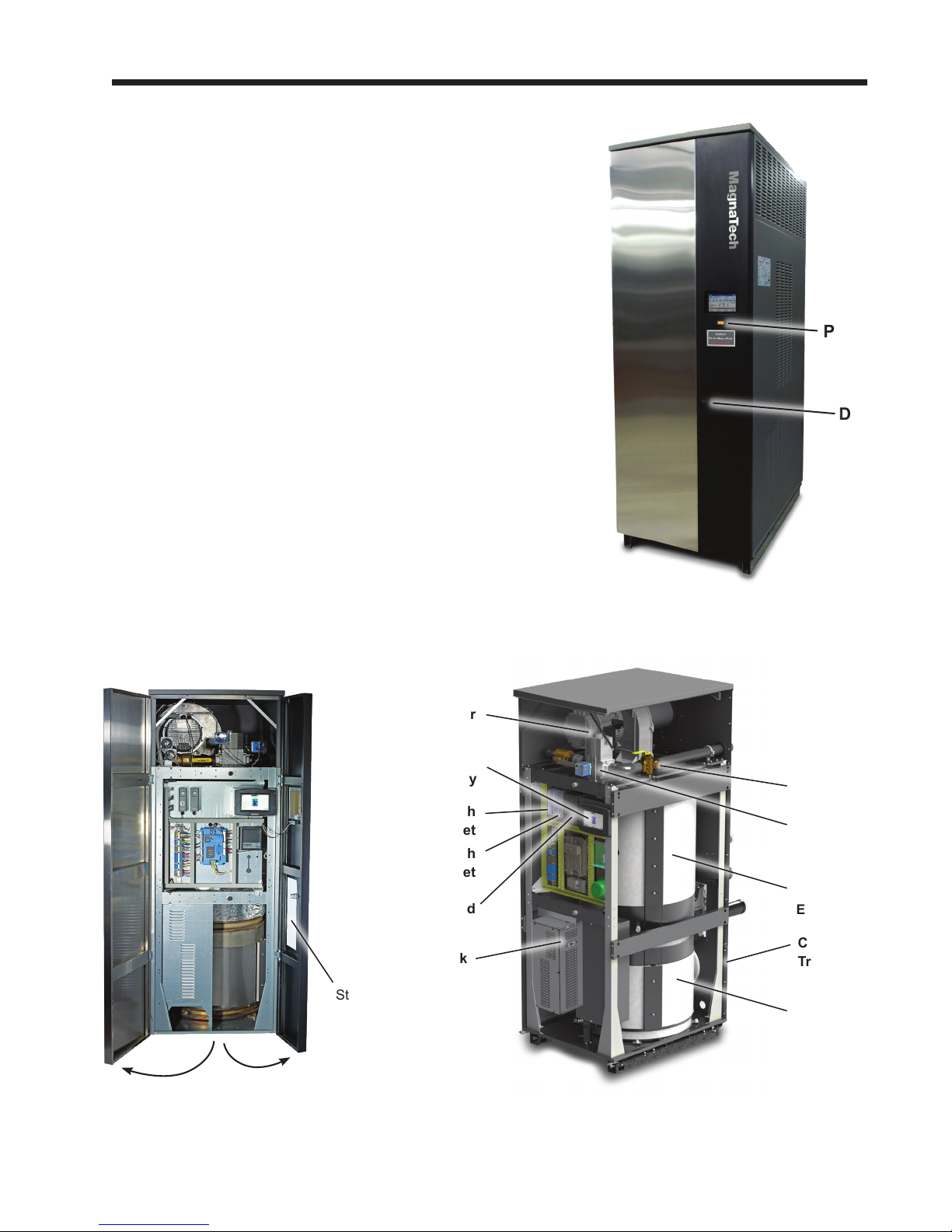
FAMILIARIZING YOURSELF
WITH THE
MagnaTech
Page 1
Power
Switch
Door
Latch
For full instructions regarding the MagnaTech, please reference
the MagnaTech Installation and Operation Manual.
Document #1293. If not available at or near the MagnaTech,
it can be downloaded at www.bradfordwhite.com
Blower
Touch Screen
Display
Automatic High
Limit Reset
Manual High
Limit Reset
Variable Speed
Pump Control
Voltage Pack
Start-Up and
Shutdown Decal
Manual
Gas Valve
Automatic
Gas Valve
Heat
Exchanger
Condensate
Trap
Condensing
Unit
Location of Components
Note - Model 3000 shown for reference.
Some components will vary slightly between the various sizes, but the User Interface & Front Panel remain the same.
Shown without jacket.
Page 3
Page 2
WARNING: If you do not follow these instructions exactly, a fire or explosion may result
causing property damage, personal injury or loss of life.
A. This appliance is equipped with an ignition device which automatically lights the pilot.
B. BEFORE OPERATING smell all around the appliance area for gas. Be sure to smell next to
the floor because some gas is heavier than air and will settle on the floor.
WHAT TO DO IF YOU SMELL GAS
Do not try to light any appliance.
Do not touch any electric switch; do not use any phone in your building.
Immediately call your gas supplier from a neighbor’s phone. Follow the gas supplier’s instructions.
If you cannot reach your gas supplier, ca
ll the fire department.
C. Use only your hand to turn the gas valve handle. Never use tools. If the valve handle will
not turn by hand, don’t try to repair it, call a qualified service technician. Force or
attempted repair may result in a fire or explosion.
D. Do not use this appliance if any part has been under water. Immediately call a qualified
service technician to inspect the appliance and to replace any part of the control system
and any ga
s control which has been under water.
1. STOP! Read the safety information above on this label.
2. Turn off all electric power to the appliance.
3. Set the thermostat to lowest setting.
4.
5. Open front doors.
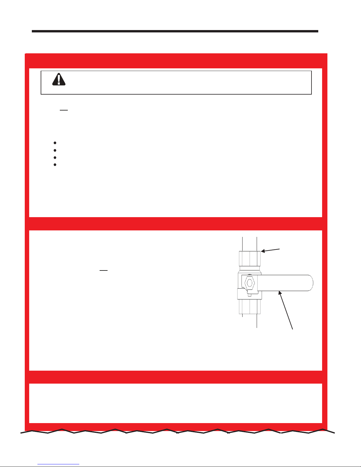
6. Turn off manual gas valve. Valve is off when valve handle is at a
right angle to gas pipe.
7. Wait five (5) minutes to clear out any gas. Then smell for gas,
including near the floor. If you do smell gas, STOP! Follow “B” in th
e
safety information above on this label. If you don’t smell gas, go to
next step.
8. Slowly turn manual gas valve to “ON”. Valve handle will be parallel to gas pipe.
9. Replace front panel.
10. Set mechanical thermostats to desired settings.
11. Turn on all electric power to the appliance.
13. If the appliance will not operate, follow the instructions “To Turn O Gas To Appliance”
12. Set operating thermostat to desired settings using boiler display.
and call your service technician or gas supplier.
1. Turn off all electric power to the appliance if service is to be performed.
2.
Set the thermostat to lowest setting.
3.
4. Turn off manual gas valve. Valve is off when valve handle is at a right angle to gas pipe.
5. Close front doors.
FOR YOUR SAFETY READ BEFORE OPERATING
OPERATING INSTRUCTIONS
TO TURN OFF GAS TO APPLIANCE
Gas inlet
Manual Gas Valve
Shown in the
“OFF” Position
Do not try to light the pilot by hand.
Open front doors.
This appliance is equipped with an ignition device which automatically
lights the pilot. Do not try to light the pilot by hand.
Start-Up and Shut-Down Decal. Located on the inside of the right side door.
BRADFORD WHITE CORP
.
Page 4

causing property damage, personal injury or loss of life.
13.
If the appliance will not operate, follow the instructions “To Turn O Gas To Appliance”
and call your service technician or gas supplier.
1. Turn off all electric power to the appliance if service is to be performed.
2.
Set the thermostat to lowest setting.
3.
4. Turn off manual gas valve. Valve is off when valve handle is at a right angle to gas pipe.
5.
Close front doors.
A. Cet appareil est équipé d'un dispositif d'allumage qui s'allume automatiquement le pilote.
N'essayez pas de lumière le pilote à la main.
B. AVANT DE FAIRE FONCTIONNER, reniflez tout autour de l’appareil pour déceler une odeur de gaz.
Reniflez près du plancher, car certains gaz sont plus lourds que l’air et peuvent s’accumuler au niveau
du sol.
QUE FAIRE SI VOUS SENTEZ UNE ODEUR DE GAZ
Ne pas tenter d’allumer d’appareil.
Appelez immédiatement votre fournisseur de gaz depuis un voisin. Suivez les instructions du
fournisseur.
Si vous ne pouvez rejoindre le fournisseur, appelez le service des incendies.
C. N’utilisez que votre main pour fermer la soupape d’arrêt de gaz. N’utilisez jamais d’outils. Si la poignêe
de la valve ne tourne
pas manuellement, ne tentez pas de la réparer. Communiquez avec un
technicien de service qualifié. Le fait de forcer ou de tenter de réparer la poignée pourrait causer un
incendie ou une explosion.
D.
N’utilisez pas cet appareil s’il a été plongé dans I’eau, même partiellement. Faites inspecter I’appareil
par un technicien qualifié et remplacez toute partie du système de contrôle et toute commande qui ont
été plongées dans I’eau.
1. ARRÊTEZ ! Lisez les instructions de sécurité sur la portion supérieure.
2. Coupez l’alimentation électrique de l’appareil.
3. Réglez le thermostat à la temperature la plus basse.
4.
Cet appareil est équipé d'un dispositif d'allumage qui s'allume
automatiquement le pilote. N'essayez pas de lumière le pilote à la main.
5. Ouvrir les portes avant.
6. Mettez la soupape d’ arrêt de gaz à << OFF >>. La valve est en
position << OFF >> lorsque la poignée se trouve à angle droit du
tuyau de gaz.
7. Attendez cinq (5) minutes afin que le gaz se dissipe. Si vous croyez
sentir une odeur de gaz,
ARRÊTEZ ! Reportez-vous aux
instructions B ci-dessus, sur cette étiquette. S’il n’y a pas d’odeur
de gaz, passez à la prochaine étape.
8. Remettez lentement la soupape d’arrêt de gaz en position
<< ON >>. La poignée sera parallèle au tuyau de gaz.
9. Replacez le couvercle avant.
10. Set thermostats mécaniques sur les réglages désirés.
11. Rétablissez l’alimentation électrique à l’appareil.
13. Si l’appareil ne fonctionne pas, suivez les directives relatives à la fermeture de l’alimentation
en gaz et
12. Réglez le thermostat de fonctionnement désirée à l'aide paramètres affichage chaudière.
communiquez avec votre technicien de service ou le fournisseur de gaz.
1. Coupez toute alimentation électrique à l’appareil si celui-ci doit faire l’objet d’un entretien.
2.
Réglez le thermostat au réglage le plus bas.
3.
4. Mettez la soupape d’arrêt de gaz à << OFF >>. La valve est en position << OFF >> lorsque la poignée
se trouve à angle droit du tuyau de gaz.
5. Fermez les portes avant.
FOR YOUR SAFETY READ BEFORE OPERATING
OPERATING INSTRUCTIONS
TO TURN OFF GAS TO APPLIANCE
H2363600-
POUR VOTRE SÉCURITÉ, LISEZ AVANT DE METTRE EN MARCHE
AVERTISSEMENT: Quiconque ne respecte pas à la lettre les instructions dans la présente notice
risque un début d' incendie ou une explosion entraînant des dommages, des blessures ou la mort.
INSTRUCTIONS DE MISE EN MARCHE
Gas inlet
Manual Gas Valve
“OFF” Position
Entrée
de Gaz
Valve de Gaz
Manule se
Trouvant en
Position “OFF”
FERMENTURE DE L’ALIMENTATION EN GAZ
Ouvrir les portes avant.
Open front doors.
The MagnaTech
Page 3
Page 5

Page 4
BRADFORD WHITE CORP
SHUTTING DOWN THE MAGNATECH
It may sometimes be necessary to shut down the MagnaTech. Here are the steps required to do this:
1. Switch off the main electrical disconnect switch.
2. Open the front access doors and close the main manual gas valve.
3. If freezing is anticipated, drain the MagnaTech. (Also be sure to protect the piping in the building from
freezing.)
The steps listed above may require qualied service personnel.
RESTARTING THE MAGNATECH
It may be necessary to restart the MagnaTech – for example, after a power interruption. Here are the steps
required to do this:
1 Reset any errors using the user interface. See the section on “About Lockouts, Holds, and Alerts.”
2 Turn up the thermostat to call for heat.
.
3. In approximately 2 seconds, the blower will operate. Ignition should occur after 35-40 seconds. It may
take as long as 2-1/2 minutes.
4. If ignition does not occur, wait 5 minutes and then repeat steps 1 through 3.
5. If, after three attempts, the unit still does not light, shut down the boiler and call your service technician.
IN THE EVENT OF POWER FAILURE
The MagnaTech will not operate during an electrical power outage. If there is an extended power outage with
danger of freezing, then the MagnaTech (and all other water systems) should be completely drained. Before
draining the unit, turn off the gas and turn off the main power switch. When you replace the unit in service,
refer to the “Installation and Operation Manual” for instructions on lling and purging.
Page 6

The MagnaTech
CONTROLS AND INDICATORS
Power
Switch
Page 5
Touch
Screen
Display
Each MagnaTech has one burner and one burner
controller. A complete lead lag system can include
up to eight MagnaTechs.
After the system starts, the Touch Screen will
automatically present the Home screen:
The icon for each burner controller will appear
in one of four colors:
Blue Normal operation
Red Lockout
Gray Standby mode (Burner
switch off)
Gray and
crossed out
Yellow Hold state. This could
Communication problem
be Anti short cycle, fan
speed transitions, etc.
To check the operation of an individual burner,
press the large icon on the Home screen. The
system will present a Status Summary screen
for that burner:
Page 7

Page 6
BRADFORD WHITE CORP
ABOUT LOCKOUTS, HOLDS, AND ALERTS
The system responds to three kinds of trouble indications:
• A”lockout” is caused by a serious problem that might involve a safety issue. Once
the controller enters a lockout, the burners will shut down, and will not be allowed
to run again until the cause of the problem is corrected, and you reset the control
system.
• The system may enter a “hold” for a period of time before locking out. This allows
the controller to see if the error becomes resolved prior to the hard lockout.
• An “alert” indicates that some feature of the control system’s operation was not
correct, delayed, or waiting for a response. This does not necessarily indicate a
problem.
If a problem occurs while the system is starting up, the system will declare a Hold or
Lockout:
.
If a problem occurs while the system is running, a Bell symbol will appear in the upper
left corner of the screen, and the system will present a note across the bottom of the
screen. If you tap the bar which includes the message, the system will present more
information about the problem. Press the OK button to indicate that you have seen the
Lockout or Alert.
If an audible alarm on the display is active, tap the Bell symbol to stop it.
Each error message includes a number. For a more detailed description of each message,
see the “Installation and Operation Manual.”
Page 8

The MagnaTech
GENERAL CARE
Keep the area around the MagnaTech clear and free from combustible materials, gasoline
and other ammable vapors and liquids. Clean the jacket surfaces with a damp cloth
and mild soap. Do not use ammable cleaning materials. Keep the vent terminal free of
obstructions. Do not pile snow against the vent terminal.
ANNUAL INSPECTION AND SERVICE
You should visually inspect the vent pipe once a year. Should any corrosion or leaks
exist, have the affected parts replaced.
Once each year a qualied service agency should conduct a detailed inspection of all ue
product carrying areas of the boiler and vent system. Follow the service instructions in
the “Installation and Operating Instructions Manual” for the MagnaTech.
Caution
Do not use this boiler if any part has been under water.
Immediately call a qualied service technician to inspect
the boiler. Any part of the control system and any gas
control which has been under water must be replaced.
WARNING
If the unit overheats or the gas supply fails to shut off, do
not turn off or disconnect the electrical supply to the pump.
Instead, shut off the gas supply at a location external to the
MagnaTech.
En cas de surchauffe ou si l’admission de gaz ne peut
être coupée, ne pas couper ni débrancher l’alimentation
électrique de la pompe. Fermer plutôt le robinet d’admission
de gaz à l’extérieur de l’appareil.
FOR SERVICE
Contact your installing contractor, gas utility, Bradford White dealer, or check www.
BradfordWhite.com for the nearest authorized representative in your area.
200 Lafayette St.
Middleville, MI 49333
Warranty: (800) 531-2111
HLW
H2359301A
www.BradfordWhite.com
Litho in U.S.A. © Bradford White 1507 Document 1294A-BW
 Loading...