

Page 1
S
TANDARD
9001
1
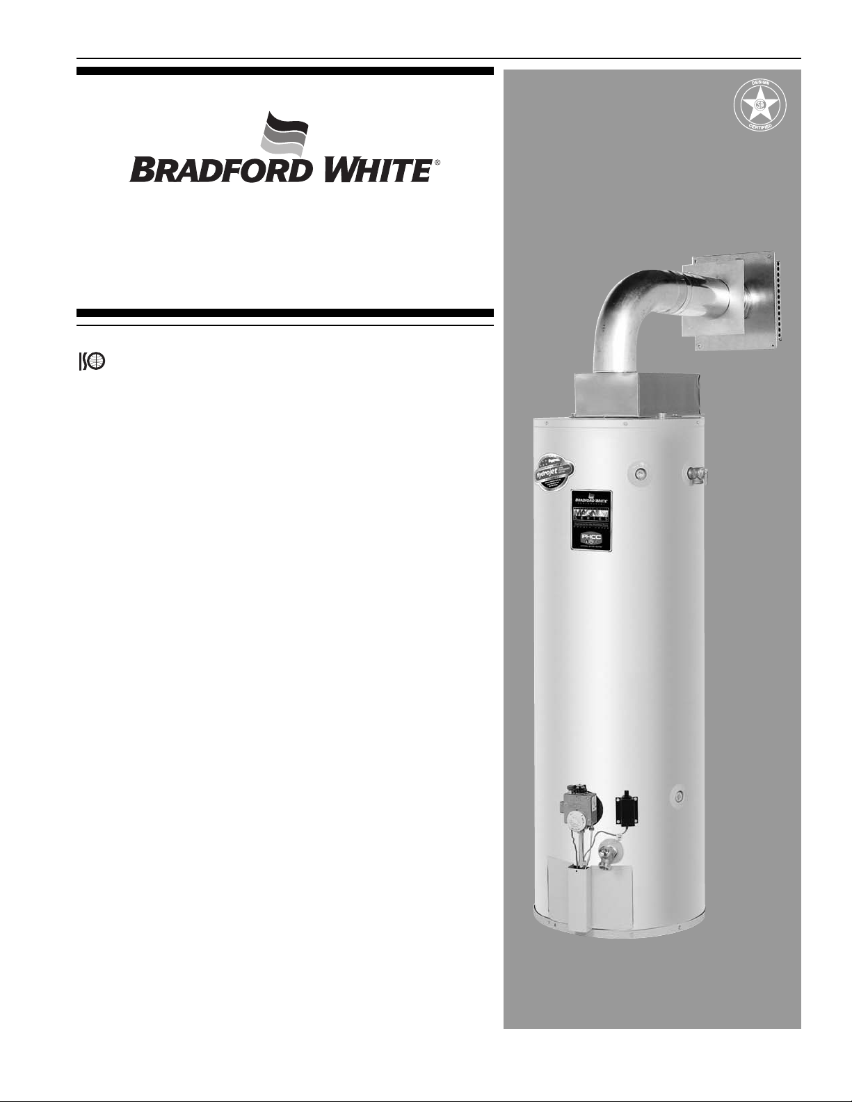
Commercial Gas Light Duty
High Input Direct Vent Water Heater
Features:
Bradford White is ISO registered to the
9001 standard.
■ 1" Non-CFC foam insulation—surrounds the tank surface, saving
energy by retarding loss of heat.
■ Closed combustion—all air for combustion is taken directly from the
outside. The co-axial vent pipe (pipe inside a pipe) draws combustion
air in through the outer pipe (6"), and exhausts the products of
combustion through the inner pipe (4").
■ Co-axial—rotational venting at top of unit.
■ No electrical power necessary.
■ Piezo igniter—for ease of lighting the pilot.
■ Water Connections—3/4" NPT factory installed true dielectric fittings.
Extends water heater life and eases installation.
■ Vitraglas®lined tank—Bradford White water heater tanks are
protected from the corrosive effects of hot water by an exclusive
ceramic porcelain-like coating. The Bradford White high silica Vitraglas
lining provides a tough interior surface for our water heater tanks.
■ Factory installed Hydrojet®Total Performance System—cold inlet
sediment reducing device. Helps prevent sediment build up in tank.
Increases first hour delivery of hot water while minimizing temperature
build up at top of tank.
■ Protective magnesium anode rod—provides added protection
against corrosion for long trouble-free service.
■ Brass drain valve.
■ T&P relief valve—factory installed.
■ Side Tappings—for space heating purposes.
■ Fully automatic controls—automatic temperature selection at your
fingertips. Built-in energy cut-off switch prevents abnormally high water
temperature for extra safety. Built-in gas pressure regulation. Fastacting thermostat starts heat recovery cycle sooner.
■ NSF construction available.
■ Optional vent kits—allow for up to 8 foot max vertical and 8 foot max
horizontal (2.4 meters)). All DH models must be terminated horizontally.
■ Three year limited warranty on steel tank—heavy gauge steel
automatically formed, rolled and welded to assure a continuous seam
for glass lining.
■ One year limited warranty on parts.
■ Design certified by CSA International. (formerly AGA and CGA)
MANUFACTURED UNDER ONE OR MORE OF THE FOLLOWING U.S. PATENTS: 7,063,133 B2; 5,954,492;
5,954,492; 5,761,379; 5,943,984; 5,081,696; 5,988,117; 6,142,216; 5,199,385; 5,574,822; 5,372,185; 5,485,879;
5,277,171; (B1)5,341,770; 5,660,165; 5,596,952; 5,682,666; 4,904,428; 5,023,031; 5,000,893; 4,669,448;
4,829,983; 4,808,356; 5,115,767; 5,092,519; 5,052,346; 4,416,222; 4,628,184; 4,861,968; 4,672,919; Re.
34,534. OTHER U.S. AND FOREIGN PATENT APPLICATIONS PENDING. CURRENT CANADIAN PATENTS:
1,272,914; 1,280,043; 1,289,832; 2,045,862; 2,112,515; 2,108,186; 2,107,012; 2,092,105.5.
®
Page 2
Sales/800-523-2931
Fax/215-641-1670
Technical Support/ 800-334-3393
Fax/269-795-1089
Warranty/800-531-2111
Fax/269-795-1089
International:
Telephone/215-641-9400
Telefax/215-641-9750
Ambler, PA
888-538-7833
Fax on Demand:
bradfordwhite.comwww.
For U.S. and Canada field service,
contact your professional installer or
local Bradford White sales representative.
Sales/Technical Support
866-690-0961
905-238-0100
Fax/905-238-0105
Mississauga, ON
www.bradfordwhitecanada.com
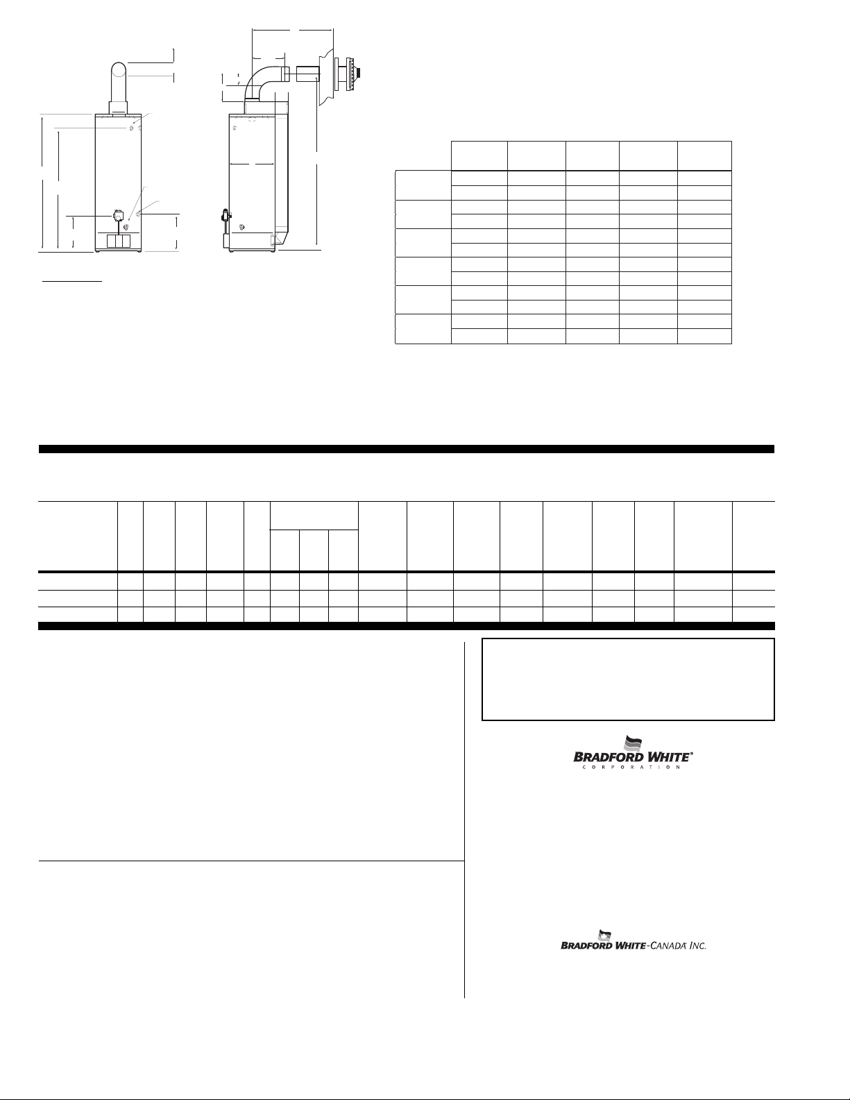
Horizontal "X"
16 1/4 18 25 1/4 37 3/4 61 5/16
17 3/16 20 11/16 35 3/16 57 7/8 107 5/16
order order
n
o add'l order
order
11 9/16
kit F kit G
kit req'd kit H
kit I
16 5/16 *order order
order order
order
1
7 1/4 kit F (2) kit G & F
kit F kit H & F
k
it F & I
1
8 1/16 order order
order order
o
rder
2
0 3/4 kit F & G kit G (2)
kit G kit G & H
k
it G & I
25 5/16
order order order order order
35 1/4
kit F kit G kit H kit H (2) kit I
38 1/16
order order order order order
57 15/16
kit H & F kit H & G kit H (2) kit H (3) kit H & I
61 3/8 order order
order order
order
Vertical "Y"
107 3/8 kit I & F kit I & G
kit I kit I & H
kit I (2)
ptional Kits
C
E & F
D
1/2” GAS
CONNECTION
SIDE WATER OUTLET
DRAIN VALV E
SIDE WATER INLET
G
A
B
6.5 inch (16.5 cm)
Min. Diameter Hole in Wall
Y
11 9/16
X
11 1/2
7 3/16”
B
oot Extension
H
O
Part Number Description
243-42516-00
243-42517-00 Kit G – Telescopes from 61⁄2" to 93⁄16"
243-42514-00 Kit H – Telescopes from 133⁄4" to 2311⁄16"
243-42512-00 Kit I – Telescopes from 4913⁄16" to 9513⁄16"
For more details on the vent kits above, please reference the
upplemental venting instructions.
s
:
Kit F – Telescopes from 43⁄4" to 511⁄16"
Horizontal Installation Only
The standard vent kit (239-42979-00) is ordered and shipped separately. The components
re as follows: 4" vent tube*, 6" Air Intake Tube, Vent Terminal, Inner Wall Term Mounting
a
Flange, Outer Wall Term. Mounting Flange, Vent Terminal Hardware, RTV Silicone Sealant,
" Vent Elbow and a 6" Air Intake Elbow.
4
* (2) = Order two of the kits referenced.
* (3) = Order three of the kits referenced.
he bold text above show what kit(s) are needed in addition to the standard vent and air
T
intake tubes. If the standard vent and air intake tubes are not used in the venting system
(those that do not have bold text) they can be discarded or saved.
or vent distances not found in the selection chart above, please contact the Product
F
anagement Department for sizing recommendations.
M
EC listed. 78% Recovery Efficiency for all models.
Energy Saver Direct Vent Models
NATURAL GAS
GPH Rec.
56°C/100°F. Rise
Model
Number
Imp. US
Gal. Gal. Input
Cap. Cap. Liters BTU KW in. mm in mm in mm in mm in mm in mm in mm in mm Lbs. kg
Imp.
Gal.USGPH
LPH
DH-50T-50B-3N 40 48 182 50,000 14.7 39 47 178 751⁄4 1411 20 508 583⁄4 1492 151⁄4 387 521⁄4 1327 521⁄4
DH-65T-55B-3N 54 65 246 55,000 16.1 43 51 193 781⁄4 1988 22 559 62 1575 151⁄4 387 56 1422 56
DH-75T-60B-3N 62 75 284 60,000 17.6 47 56 212 751⁄2 1918 241⁄2 622 59 1499 151⁄4 387 52 1321 52
All propane gas heaters are equipped with Cast Iron Burner. Change suffix “BN”
to “CX”.
Suitable for Water (Potable) Heating and Space Heating
Toxic chemicals, such as those used for boiler treatment, shall NEVER be introduced
into this system. This unit may NEVER be connected to any existing heating system
or component(s) previously used with a non-potable water heating appliance.
ABCDEFG
Ht. to
Center
Line of
Vent
C
Jacket
Dia.
Ht. to
Top of
Heater
Ht. to
Gas
Conn.
(LP)
Propane Gas Inputs
DH-50T-50-3CX 48,000 BTU/H 14.1 KW 38 45 170
DH-75T-60-3CX 57,000 BTU/H 16.7 KW
Ht. to
T&P
Conn.
Space
Htg.
Outlet
1327
1422
1320
Space
Htg.
Inlet
4/6 102/152 197/89.4
153⁄4 400
4/6 102/152 243/110
153⁄4 400
4/6 102/152 281/127
161⁄2 419
Recovery at
50°C Rise and 100°F Rise
Imp. U.S. Liters/
GPH GPH Hr.
44 53 200
General
All gas water heaters are certified at 300 PSI (2068 kPa) test pressure and 150 PSI
(1034 kPa) working pressure. All water connections are 3⁄4" (19mm) NPT on
8" (703mm) centers on top of unit, all gas connections 1⁄2" (13mm). All models design
certified by CSA International (formerly AGA and CGA). Recovery based on rated
efficiency.
Meets NAECA requirements. All natural gas models meet SCAQMD
requirements.
Dimensions and specifications subject to change without notice in accordance
with our policy of continuous product improvement.
Sample Specification
The water heater shall be a Bradford White model with a rated storage capacity of not less
than _______ gallons (liters), a minimum gas input of _______ BTUH (KWH), and a
minimum recovery of _______ GPH (LPH) at 100
design certified by CSA International (formerly AGA and CGA). The tank shall be lined with
Vitraglas®vitreous enamel. The tank shall have one extruded magnesium anode rod. The
heater shall be insulated with Non-CFC foam insulation. This water heater shall be
equipped with an ASME rated T&P relief valve. The entire installation shall be in
compliance with state and local codes and ordinances.
Vitraglas®and Hydrojet®are registered trademarks of Bradford White®Corporation.
©2006, Bradford White Corporation. All rights reserved.
705-B-HIDV-1106-A Printed in U.S.A.
°F (56°C) temperature rise. It shall be
PRODUCTS ONL Y FOR PROFESSIONALS
Vent
Dia.
Approx.
Shipping
Weight
 Loading...