

B&R PP21, PP41 User Manual

Power Panel
User's Manual
Version: 1.4 (July 2002)
Model No.: MAPP01-E
We reserve the right to change the contents of this manual without warning. The information
contained herein is believed to be accurate as of the date of publication, however, Bernecker +
Rainer Industrie-Elektronik Ges.m.b.H. makes no warranty, expressed or implied, with regards
to the products or the documentation contained within this book. In addition, Bernecker + Rainer
Industrie-Elektronik Ges.m.b.H. shall not be liable in the event of incidental or consequential
damages in connection with or arising from the furnishing, performance, or use of these
products.
Software names, hardware names, and trademarks used in this document are registered by the
Power Panel User's Manual 1

2 Power Panel User's Manual

Chapter 1: Power Panel
Chapter 2: Technical Appendix
Index
Power Panel User's Manual 3

4 Power Panel User's Manual

Contents
Chapter 1: Power Panel ................................................................... 7
1. Safety Guidelines .................................................................................................. 7
1.1 Introduction ...................................................................................................... 7
1.2 Intended Use .................................................................................................... 7
1.3 Transport and Storage ..................................................................................... 7
1.4 Installation ........................................................................................................ 8
1.5 Operation ......................................................................................................... 8
1.5.1 Protection against Touching Electrical Parts .............................................. 8
2. Safety Notices ....................................................................................................... 9
3. Manual History ...................................................................................................... 9
4. General Information ............................................................................................ 10
4.1 Introduction .................................................................................................... 10
4.2 Features ......................................................................................................... 10
4.3 Photo .............................................................................................................. 11
5. Power Panel PP21 .............................................................................................. 12
5.1 Order Data ..................................................................................................... 12
5.2 Photo .............................................................................................................. 13
5.3 Technical Data ............................................................................................... 13
5.4 Images ........................................................................................................... 17
5.5 Dimensions .................................................................................................... 18
6. Power Panel PP41 .............................................................................................. 19
6.1 Order Data ..................................................................................................... 19
6.2 Photo .............................................................................................................. 20
6.3 Technical Data ............................................................................................... 20
6.4 Images ........................................................................................................... 24
6.5 Dimensions .................................................................................................... 25
7. Power Panel Expansion EX101 Module ............................................................. 25
7.1 General Information ....................................................................................... 25
7.2 Order Data ..................................................................................................... 25
7.3 Photo .............................................................................................................. 26
7.4 Technical Data ............................................................................................... 27
7.5 Images ........................................................................................................... 27
7.6 Dimensions .................................................................................................... 28
7.7 Installation ...................................................................................................... 29
8. IF370 CAN Interface Module ............................................................................... 30
8.1 General Information ....................................................................................... 30
8.2 Order Data ..................................................................................................... 30
Power Panel User's Manual 5

Contents
8.3 Photo .............................................................................................................. 30
8.4 Technical Data ............................................................................................... 30
8.5 Status LEDs ................................................................................................... 31
8.6 Pin Assignments ............................................................................................ 31
9. Mounting Instructions .......................................................................................... 32
10. Device Label ..................................................................................................... 33
11. Programming ..................................................................................................... 33
11.1 Programming the PLC CPU ......................................................................... 33
11.2 Visualization ................................................................................................. 33
12. Description of Components ............................................................................... 34
12.1 Status LEDs ................................................................................................. 34
12.2 Power Supply ............................................................................................... 34
12.3 Interfaces ..................................................................................................... 35
12.3.1 CAN Interface ......................................................................................... 35
12.3.2 RS232 Interface ..................................................................................... 36
12.4 Operating Mode Switch ................................................................................ 36
12.5 Programming System Flash ......................................................................... 37
12.6 PCMCIA Slot ................................................................................................ 37
12.6.1 Limitations when using Memory Cards .................................................. 38
12.7 Power Panel Interface .................................................................................. 38
12.8 Screw-in Module Overview .......................................................................... 38
12.9 Data/Realtime Buffering ............................................................................... 39
12.10 Digital Inputs .............................................................................................. 40
12.10.1 Terminal Block Connections ................................................................ 40
12.10.2 Input Circuit Diagram ........................................................................... 40
12.10.3 Connection Example ............................................................................ 41
12.11 Digital Outputs ............................................................................................ 41
12.11.1 Terminal Block Connections ............................................................... 41
12.11.2 Output Circuit Diagram ......................................................................... 42
12.11.3 Output Circuit Diagram for Potential-Free Relay Contact .................... 42
12.11.4 Connection Example for Outputs 1 - 8 ................................................ 42
12.11.5 Connection Example for Potential-Free Relay Contact ........................ 43
13. Changing the Battery ........................................................................................ 44
13.1 Battery Data ................................................................................................. 44
13.2 Buffer Duration ............................................................................................. 44
Chapter 2: Technical Appendix .................................................... 47
1. Décor Foil (polyester foil) .................................................................................... 47
2. Characters for LC Displays (English/Katakana) .................................................. 48
6 Power Panel User's Manual

Power Panel • Safety Guidelines
Chapter 1 • Power Panel
1. Safety Guidelines
1.1 Introduction
Programmable logic controllers (e.g. PLCs, etc.), operating and monitoring devices (e.g.
Industrial PCs, Power Panels, Mobile Panels, etc.) as well as the B&R uninterruptible power
supplies have been designed, developed and manufactured for conventional use in industry.
They were not designed, developed and manufactured for any use involving serious risks or
hazards that without the implementation of exceptionally stringent safety precautions could lead
to death, injury, serious physical damage or loss of any other kind. Such risks and hazards
include in particular the use of these devices in the monitoring of nuclear reactions in nuclear
power plants and of flight control systems, in flight safety, in the control of mass transportation
systems, in medical life support systems, and in the control of weapons systems.
Both when using programmable logic controllers and when using operating and monitoring
devices as control systems in conjunction with a Soft PLC (e.g. B&R Automation Runtime or
comparable products) or a Slot PLC (e.g. B&R LS251 or comparable products), the safety
precautions applying to industrial control systems (e.g. the provision of safety devices such as
emergency stop circuits, etc.) in accordance with applicable national and international
regulations must be observed. The same applies for all other devices connected to the system,
such as drives.
Chapter 1
Power Panel
All tasks such as installation, commissioning and service may only be carried out by qualified
personnel. Qualified personnel are persons who are familiar with transport, mounting,
installation, commissioning and operation of the product and have the appropriate qualifications
(e.g. IEC 60364). National accident prevention guidelines must be followed. The safety
guidelines, connection descriptions (rating plate and documentation) and limit values listed in the
technical data must be read carefully before installation and commissioning and must be
observed.
1.2 Intended Use
Electronic devices are generally not fail-safe. In the event of a failure on the programmable
control system, operating or monitoring device or uninterruptible power supply, the user is
responsible for ensuring that other devices that may be connected, such as motors, are made
safe
1.3 Transport and Storage
During transport and storage, the devices must be protected from excessive stress (mechanical
load, temperature, humidity, aggressive atmosphere).
Power Panel User's Manual 7

Power Panel • Safety Guidelines
1.4 Installation
• The installation must take place according to the documentation using suitable
equipment.
• The devices may only be installed when isolated from the power supply and by
qualified personnel.
• General safety regulations and nationally applicable accident prevention guidelines
must be observed.
• Electrical installation must be carried out according to the relevant guidelines (e.g.
line cross section, fuse, protective ground connection).
1.5 Operation
1.5.1 Protection against Touching Electrical Parts
The operation of programmable logic controlllers, operating and monitoring devices and
uninterruptible power supplies necessarily means that certain components must carry
dangerous voltage levels of over 42 VDC. A life-threatening electric shock could occur if you
touch these parts. This could result in death, severe injury or material damage.
Before turning on programmable control systems, operating and monitoring devices and the
uninterruptible power supply, ensure that the housing is properly connected to protective ground
(PE rail). The ground connection must be established even when testing the operating and
monitoring devices and the uninterruptible power supply or when operating them for only a short
time.
Before turning the device on, make sure that all voltage-carrying parts are securely covered.
During operation, all covers must remain closed.
8 Power Panel User's Manual
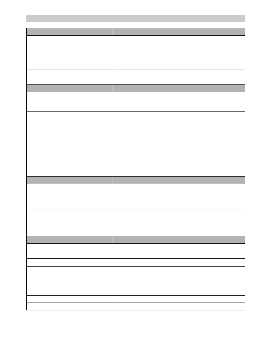
2. Safety Notices
Safety notices are organized as follows:
Power Panel • Safety Notices
Safety Notice Description
Disregarding the safety regulations and guidelines can result in severe injury or heavy damage to material
or the product.
Disregarding the safety regulations and guidelines can result in injury or damage to material and the product.
European dimension standards are valid for all dimension diagrams (e.g.
dimension diagrams, etc.).
3. Manual History
Version Date Comments
1.4 22.05.2002 Changes/New features
- Safety guidelines added
- Error correction: Digital inputs for PP21/PP41: Electrical isolation for input - output Yes
or digital outputs for PP21/PP41: Electrical isolation for input - output Output - Input Yes
- Pin assignment RS232 interface updated
- Guidelines for using PCMCIA memory cards regarding Tasks added
- Input and output circuit diagrams added
- Technical data regarding switching threshold for digital inputs for PP21 and PP41 deleted
Table 1: Safety notices
Chapter 1
Power Panel
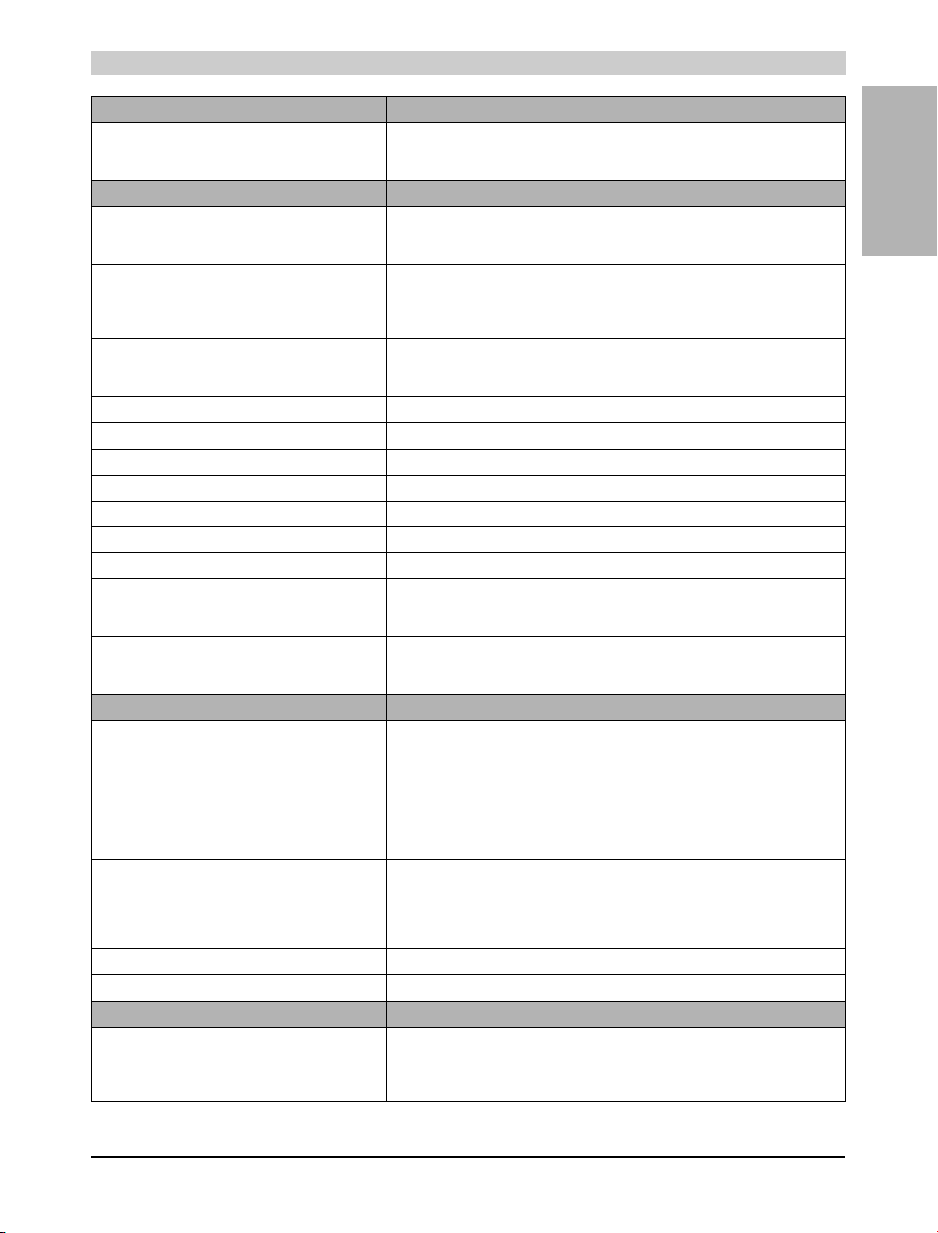
1.3 04.12.2001 Changes/New features
1.2 09.11.2001 Changes/New features
- Operating system updates using the MEMCARD and mode switch described in more detail
- PCMCIA interface description added
- 7AT324.70 screw-in module included
- "Mode switch" picture replaced
- Battery buffer time improved (10 minutes guaranteed)
- Correction of description for the inputs and outputs (they are electrically isolated)
Table 2: Manual history
Power Panel User's Manual 9

Power Panel • General Information
4. General Information
4.1 Introduction
B&R offers the B&R Power Panel PP21 and PP41 for automation of small to midsize machines
and systems. The Power Panel is a combination of operator panel and controller in one device.
A 4 x 20 character text display or a ¼ VGA graphic display can be selected. Each Power Panel
is equipped with a powerful PLC CPU including integrated digital I/O and six slots for B&R
SYSTEM 2003 screw-in modules. An expansion module is offered for the Power Panel PP41
which allows the operation of B&R SYSTEM 2005 interface module inserts.
The visualization application is created using B&R Automation Studio™. Programming the PLC
CPU is done using B&R Automation Studio™ or PG2000.
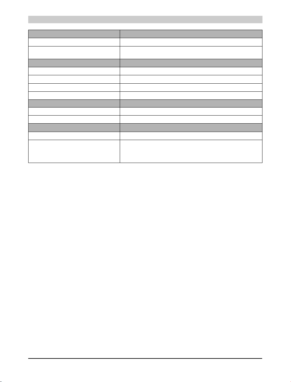
4.2 Features
• 24 VDC supply voltage
• Software compatible with B&R 2000 PLC family
• PCMCIA Slot
• 10 digital inputs
• 8 digital outputs
• 1 potential-free relay contact
• RS232 Interface
• CAN bus interface
• 6 slots for B&R SYSTEM 2003 screw-in modules, 3 of which support additional functions
(TPU) such as event counting, trigger functions, stepper motor control, frequency
measurement or communication modules
• Expansion module for the Power Panel PP41 which allows the operation of B&R SYSTEM
2005 interface module inserts
10 Power Panel User's Manual
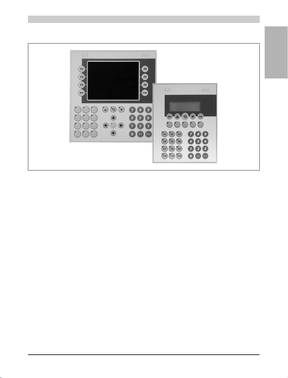
4.3 Photo
Figure 1: Power Panel
Power Panel • General Information
Chapter 1
Power Panel
Power Panel User's Manual 11
Power Panel • Power Panel PP21
5. Power Panel PP21
5.1 Order Data
Model Number Short Description
Power Panel
4P0420.00-490
0AC201.9 Lithium batteries, 5 pcs., 3 V / 950 mAh, button cell
0MC111.9 PCMCIA memory card, 2MB FlashPROM
0MC211.9 PCMCIA memory card, 2MB SRAM
4A0035.00-000 Set of legend strips for 4P0420.00-490 (for 10 devices)
7TB712.9 Terminal block, 12 pin, screw clamps
7TB712.91 Terminal block, 12 pin, cage clamps
7TB712:90-02 Terminal block, 12 pin, 20 pcs., screw clamps
7TB712:91-02 Terminal block, 12 pin, 20 pcs., cage clamps
1) All parts required to install the Power Panel, including key legend sheets, are included in its delivery. The backup battery and the 4 pin
1)
Power Panel PP21, LC display 4x20 characters, background lighting, 34 function keys,
system compatible 2003 CPU, 700Kb SRAM, 1.4MB FlashPROM, 1 PCMCIA slot, 1
RS232 interface, 1 CAN interface: electrically isolated, network capable, 6 slots for screwin modules, 10 digital inputs 24 VDC, 8 digital outputs 24 VDC, 0.4 A, IP65 protection (from
front), 155 x 190 mm (WxH), 24 VDC, Order TB712 terminal blocks separately!
Accessories
Table 3: Order data for the Power Panel PP21
terminal block for the supply are also included. Two 12 pin terminal blocks must be ordered separately.
12 Power Panel User's Manual
5.2 Photo
5.3 Technical Data
Power Panel • Power Panel PP21
Figure 2: Power Panel PP21
Chapter 1
Power Panel
Product ID PP21
General Information
C-UL-US Listed In preparation
Standards
Temperature
Shock / Tests Carried Out
Vibration / Tests Carried Out
Emission / Tests Carried Out
Immunity / Tests Carried Out
Processor
Additional I/O Processor Handles I/O data points
Instruction Cycle Time
(Average value with 70% bit and
30% analog processing)
Standard Memory
User RAM
System PROM
User PROM
IEC61131-2 / IEC60068-2-x
IEC61131-2 / IEC60068-2-27
IEC61131-2 / IEC60068-2-6
EN50081-2 / EN55022+A1
IEC61131-2 / IEC61000-4-x
0.4 µs
700 Kbyte SRAM
600 KByte FlashPROM
1.4 MByte FlashPROM
Table 4: Technical data for PP21
Power Panel User's Manual 13
Power Panel • Power Panel PP21
Product ID PP21
Data Buffering
Backup Battery
Buffer Current
Typical
Maximum
Hardware Watchdog Yes
Voltage Monitoring The internal supply is monitored for overvoltage and undervoltage
Fan No
Peripherals
Real-Time Clock
Resolution
Status Display LEDs
System Bus for Expansions No
Slots for B&R 2003 Screw-in Modules
Suitable for IF Modules (without CAN)
TPU Functionality Support
Suitable for CAN Communication
PCMCIA slot (See "PCMCIA Slot" on page 37.)
Standard
Card Height
Card Type
Memory Size
SRAM
FlashPROM
Standard Communication Interfaces
Application Interface IF1
Electrical Isolation
Design
Max. Distance
Max. Baud Rate
Application Interface IF2
Electrical Isolation
Design
Max. Distance
Max. Baud Rate
Digital Inputs
Number of Inputs 10
Inputs with Additional Functions (TPU) Inputs 1-4
Input Frequency (TPU) 50 kHz (Incremental encoder operation)
Wiring Sink
Input Voltage
Minimum
Nominal
Maximum
Input Current at Nominal Voltage Approx. 4 mA
Input Delay Max. 1 ms (not TPU)
Table 4: Technical data for PP21 (cont.)
Lithium battery 3 V / 950 mAh
10 µA
200 µA
Nonvolatile
1 sec
6
Slots 1-3
Slot 1 with interface module 4IF370.7
JEIDA V 4.0 or PCMCIA Standard Release 2.0
Slots 4-6
1
Max. 3 mm
Memory cards
Max. 4 MByte
Max. 4 MByte
RS232
No
9 pin DSUB plug
15 m / 19200 Baud
115.2 kBaud
CAN
Yes
9 pin DSUB plug
1,000 m
500 kBaud
18 VDC
24 VDC
30 VDC
14 Power Panel User's Manual
Power Panel • Power Panel PP21
Product ID PP21
Electrical Isolation
Input - PLC
Input - Outp ut
Digital Outputs
Amount/Type
Highside Driver IC (Transistor)
Potential-Free Relay Contact
Switching Voltage
Minimum
Nominal
Maximum
Continuous Current per
Output
Module
Load for Potential-Free Relay Contact Max. 0.5 A
Leakage Current when Switched Off 12 µA
Overload Protection Yes
Switching On after Overload Cutoff Automatically within seconds (depends on the panel temperature)
Continuous Short Circuit Current Typ. 4 A
Internal Protective Circuit Yes
Braking Voltage when Switching Off Inductive Loads 47 V
Switching Delay
Log. 0 - Log. 1
Log. 1 - Log. 0
Electrical Isolation
Output - PLC
Output - Input
HMI
Display
Type
Number of Lines
Number of Characters/Line
Character Height
Background Lighting
Character Set
Reading Angle
Keyboard
Number of Keys
Design
Function Keys
System Keys
Front Multi-layered front with insertion slots for key legends
Protection According to IEC 60529 IP65 (from front)
Power Supply
Input Voltage
Minimum
Nominal
Maximum
Covered keypad with metallic snap-action disks
17, with LEDs, labeled with legend sheets
17 (number block, control keys)
Table 4: Technical data for PP21 (cont.)
Yes
Yes
8
1
18 VDC
24 VDC
30 VDC
Max. 0.4 A
Max. 3.2 A
Max. 450 µs
Max. 450 µs
Yes
Yes
LC Display
4
20
4.75 mm
LED
English/Katakana
Approx. 60 °
34 membrane keys
18 VDC
24 VDC
30 VDC
Chapter 1
Power Panel
Power Panel User's Manual 15
Power Panel • Power Panel PP21
Product ID PP21
Power Consumption Max. 20 W
Output Power for Screw-in Modules and
PCMCIA Interface
Operational Conditions
Installation Vertical, ±45°
Altitude Max. 3,000 m
Environment Temperature during Operation 0 to 50 °C
Relative Humidity during Operation 10 to 90% (non-condensing)
Storage Conditions
Storage Temperature -20 to 60 °C
Relative Humidity for Storage 5 to 95 % (non-condensing)
Mechanical Characteristics
Weight Approx. 1.25 kg
Dimensions
Width
Height
Depth
Table 4: Technical data for PP21 (cont.)
10 W
155 mm
190 mm
84.4 mm
16 Power Panel User's Manual
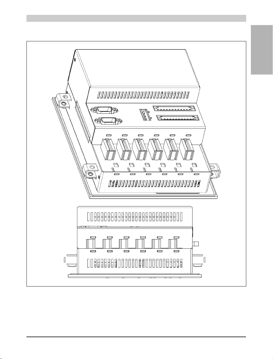
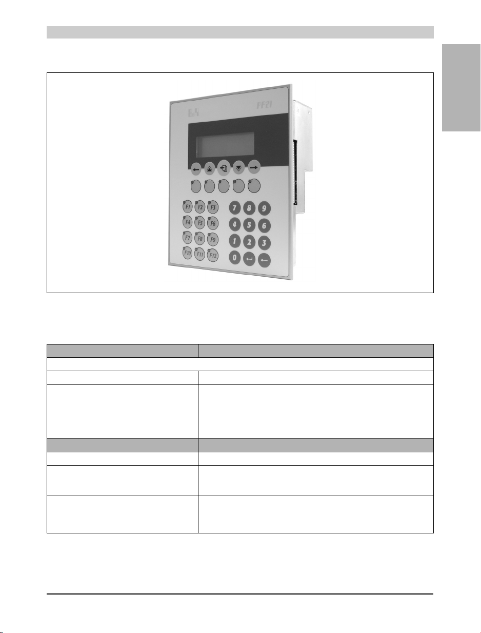
5.4 Images
Power Panel • Power Panel PP21
Chapter 1
Power Panel
Figure 3: PP21
Power Panel User's Manual 17
 Loading...