

Page 1

Power Panel
User's Manual
Version: 1.4 (July 2002)
Model No.: MAPP01-E
We reserve the right to change the contents of this manual without warning. The information
contained herein is believed to be accurate as of the date of publication, however, Bernecker +
Rainer Industrie-Elektronik Ges.m.b.H. makes no warranty, expressed or implied, with regards
to the products or the documentation contained within this book. In addition, Bernecker + Rainer
Industrie-Elektronik Ges.m.b.H. shall not be liable in the event of incidental or consequential
damages in connection with or arising from the furnishing, performance, or use of these
products.
Software names, hardware names, and trademarks used in this document are registered by the
Power Panel User's Manual 1
Page 2

2 Power Panel User's Manual
Page 3

Chapter 1: Power Panel
Chapter 2: Technical Appendix
Index
Power Panel User's Manual 3
Page 4

4 Power Panel User's Manual
Page 5

Contents
Chapter 1: Power Panel ................................................................... 7
1. Safety Guidelines .................................................................................................. 7
1.1 Introduction ...................................................................................................... 7
1.2 Intended Use .................................................................................................... 7
1.3 Transport and Storage ..................................................................................... 7
1.4 Installation ........................................................................................................ 8
1.5 Operation ......................................................................................................... 8
1.5.1 Protection against Touching Electrical Parts .............................................. 8
2. Safety Notices ....................................................................................................... 9
3. Manual History ...................................................................................................... 9
4. General Information ............................................................................................ 10
4.1 Introduction .................................................................................................... 10
4.2 Features ......................................................................................................... 10
4.3 Photo .............................................................................................................. 11
5. Power Panel PP21 .............................................................................................. 12
5.1 Order Data ..................................................................................................... 12
5.2 Photo .............................................................................................................. 13
5.3 Technical Data ............................................................................................... 13
5.4 Images ........................................................................................................... 17
5.5 Dimensions .................................................................................................... 18
6. Power Panel PP41 .............................................................................................. 19
6.1 Order Data ..................................................................................................... 19
6.2 Photo .............................................................................................................. 20
6.3 Technical Data ............................................................................................... 20
6.4 Images ........................................................................................................... 24
6.5 Dimensions .................................................................................................... 25
7. Power Panel Expansion EX101 Module ............................................................. 25
7.1 General Information ....................................................................................... 25
7.2 Order Data ..................................................................................................... 25
7.3 Photo .............................................................................................................. 26
7.4 Technical Data ............................................................................................... 27
7.5 Images ........................................................................................................... 27
7.6 Dimensions .................................................................................................... 28
7.7 Installation ...................................................................................................... 29
8. IF370 CAN Interface Module ............................................................................... 30
8.1 General Information ....................................................................................... 30
8.2 Order Data ..................................................................................................... 30
Power Panel User's Manual 5
Page 6

Contents
8.3 Photo .............................................................................................................. 30
8.4 Technical Data ............................................................................................... 30
8.5 Status LEDs ................................................................................................... 31
8.6 Pin Assignments ............................................................................................ 31
9. Mounting Instructions .......................................................................................... 32
10. Device Label ..................................................................................................... 33
11. Programming ..................................................................................................... 33
11.1 Programming the PLC CPU ......................................................................... 33
11.2 Visualization ................................................................................................. 33
12. Description of Components ............................................................................... 34
12.1 Status LEDs ................................................................................................. 34
12.2 Power Supply ............................................................................................... 34
12.3 Interfaces ..................................................................................................... 35
12.3.1 CAN Interface ......................................................................................... 35
12.3.2 RS232 Interface ..................................................................................... 36
12.4 Operating Mode Switch ................................................................................ 36
12.5 Programming System Flash ......................................................................... 37
12.6 PCMCIA Slot ................................................................................................ 37
12.6.1 Limitations when using Memory Cards .................................................. 38
12.7 Power Panel Interface .................................................................................. 38
12.8 Screw-in Module Overview .......................................................................... 38
12.9 Data/Realtime Buffering ............................................................................... 39
12.10 Digital Inputs .............................................................................................. 40
12.10.1 Terminal Block Connections ................................................................ 40
12.10.2 Input Circuit Diagram ........................................................................... 40
12.10.3 Connection Example ............................................................................ 41
12.11 Digital Outputs ............................................................................................ 41
12.11.1 Terminal Block Connections ............................................................... 41
12.11.2 Output Circuit Diagram ......................................................................... 42
12.11.3 Output Circuit Diagram for Potential-Free Relay Contact .................... 42
12.11.4 Connection Example for Outputs 1 - 8 ................................................ 42
12.11.5 Connection Example for Potential-Free Relay Contact ........................ 43
13. Changing the Battery ........................................................................................ 44
13.1 Battery Data ................................................................................................. 44
13.2 Buffer Duration ............................................................................................. 44
Chapter 2: Technical Appendix .................................................... 47
1. Décor Foil (polyester foil) .................................................................................... 47
2. Characters for LC Displays (English/Katakana) .................................................. 48
6 Power Panel User's Manual
Page 7

Power Panel • Safety Guidelines
Chapter 1 • Power Panel
1. Safety Guidelines
1.1 Introduction
Programmable logic controllers (e.g. PLCs, etc.), operating and monitoring devices (e.g.
Industrial PCs, Power Panels, Mobile Panels, etc.) as well as the B&R uninterruptible power
supplies have been designed, developed and manufactured for conventional use in industry.
They were not designed, developed and manufactured for any use involving serious risks or
hazards that without the implementation of exceptionally stringent safety precautions could lead
to death, injury, serious physical damage or loss of any other kind. Such risks and hazards
include in particular the use of these devices in the monitoring of nuclear reactions in nuclear
power plants and of flight control systems, in flight safety, in the control of mass transportation
systems, in medical life support systems, and in the control of weapons systems.
Both when using programmable logic controllers and when using operating and monitoring
devices as control systems in conjunction with a Soft PLC (e.g. B&R Automation Runtime or
comparable products) or a Slot PLC (e.g. B&R LS251 or comparable products), the safety
precautions applying to industrial control systems (e.g. the provision of safety devices such as
emergency stop circuits, etc.) in accordance with applicable national and international
regulations must be observed. The same applies for all other devices connected to the system,
such as drives.
Chapter 1
Power Panel
All tasks such as installation, commissioning and service may only be carried out by qualified
personnel. Qualified personnel are persons who are familiar with transport, mounting,
installation, commissioning and operation of the product and have the appropriate qualifications
(e.g. IEC 60364). National accident prevention guidelines must be followed. The safety
guidelines, connection descriptions (rating plate and documentation) and limit values listed in the
technical data must be read carefully before installation and commissioning and must be
observed.
1.2 Intended Use
Electronic devices are generally not fail-safe. In the event of a failure on the programmable
control system, operating or monitoring device or uninterruptible power supply, the user is
responsible for ensuring that other devices that may be connected, such as motors, are made
safe
1.3 Transport and Storage
During transport and storage, the devices must be protected from excessive stress (mechanical
load, temperature, humidity, aggressive atmosphere).
Power Panel User's Manual 7
Page 8

Power Panel • Safety Guidelines
1.4 Installation
• The installation must take place according to the documentation using suitable
equipment.
• The devices may only be installed when isolated from the power supply and by
qualified personnel.
• General safety regulations and nationally applicable accident prevention guidelines
must be observed.
• Electrical installation must be carried out according to the relevant guidelines (e.g.
line cross section, fuse, protective ground connection).
1.5 Operation
1.5.1 Protection against Touching Electrical Parts
The operation of programmable logic controlllers, operating and monitoring devices and
uninterruptible power supplies necessarily means that certain components must carry
dangerous voltage levels of over 42 VDC. A life-threatening electric shock could occur if you
touch these parts. This could result in death, severe injury or material damage.
Before turning on programmable control systems, operating and monitoring devices and the
uninterruptible power supply, ensure that the housing is properly connected to protective ground
(PE rail). The ground connection must be established even when testing the operating and
monitoring devices and the uninterruptible power supply or when operating them for only a short
time.
Before turning the device on, make sure that all voltage-carrying parts are securely covered.
During operation, all covers must remain closed.
8 Power Panel User's Manual
Page 9
2. Safety Notices
Safety notices are organized as follows:
Power Panel • Safety Notices
Safety Notice Description
Disregarding the safety regulations and guidelines can result in severe injury or heavy damage to material
or the product.
Disregarding the safety regulations and guidelines can result in injury or damage to material and the product.
European dimension standards are valid for all dimension diagrams (e.g.
dimension diagrams, etc.).
3. Manual History
Version Date Comments
1.4 22.05.2002 Changes/New features
- Safety guidelines added
- Error correction: Digital inputs for PP21/PP41: Electrical isolation for input - output Yes
or digital outputs for PP21/PP41: Electrical isolation for input - output Output - Input Yes
- Pin assignment RS232 interface updated
- Guidelines for using PCMCIA memory cards regarding Tasks added
- Input and output circuit diagrams added
- Technical data regarding switching threshold for digital inputs for PP21 and PP41 deleted
Table 1: Safety notices
Chapter 1
Power Panel
1.3 04.12.2001 Changes/New features
1.2 09.11.2001 Changes/New features
- Operating system updates using the MEMCARD and mode switch described in more detail
- PCMCIA interface description added
- 7AT324.70 screw-in module included
- "Mode switch" picture replaced
- Battery buffer time improved (10 minutes guaranteed)
- Correction of description for the inputs and outputs (they are electrically isolated)
Table 2: Manual history
Power Panel User's Manual 9
Page 10

Power Panel • General Information
4. General Information
4.1 Introduction
B&R offers the B&R Power Panel PP21 and PP41 for automation of small to midsize machines
and systems. The Power Panel is a combination of operator panel and controller in one device.
A 4 x 20 character text display or a ¼ VGA graphic display can be selected. Each Power Panel
is equipped with a powerful PLC CPU including integrated digital I/O and six slots for B&R
SYSTEM 2003 screw-in modules. An expansion module is offered for the Power Panel PP41
which allows the operation of B&R SYSTEM 2005 interface module inserts.
The visualization application is created using B&R Automation Studio™. Programming the PLC
CPU is done using B&R Automation Studio™ or PG2000.
4.2 Features
• 24 VDC supply voltage
• Software compatible with B&R 2000 PLC family
• PCMCIA Slot
• 10 digital inputs
• 8 digital outputs
• 1 potential-free relay contact
• RS232 Interface
• CAN bus interface
• 6 slots for B&R SYSTEM 2003 screw-in modules, 3 of which support additional functions
(TPU) such as event counting, trigger functions, stepper motor control, frequency
measurement or communication modules
• Expansion module for the Power Panel PP41 which allows the operation of B&R SYSTEM
2005 interface module inserts
10 Power Panel User's Manual
Page 11
4.3 Photo
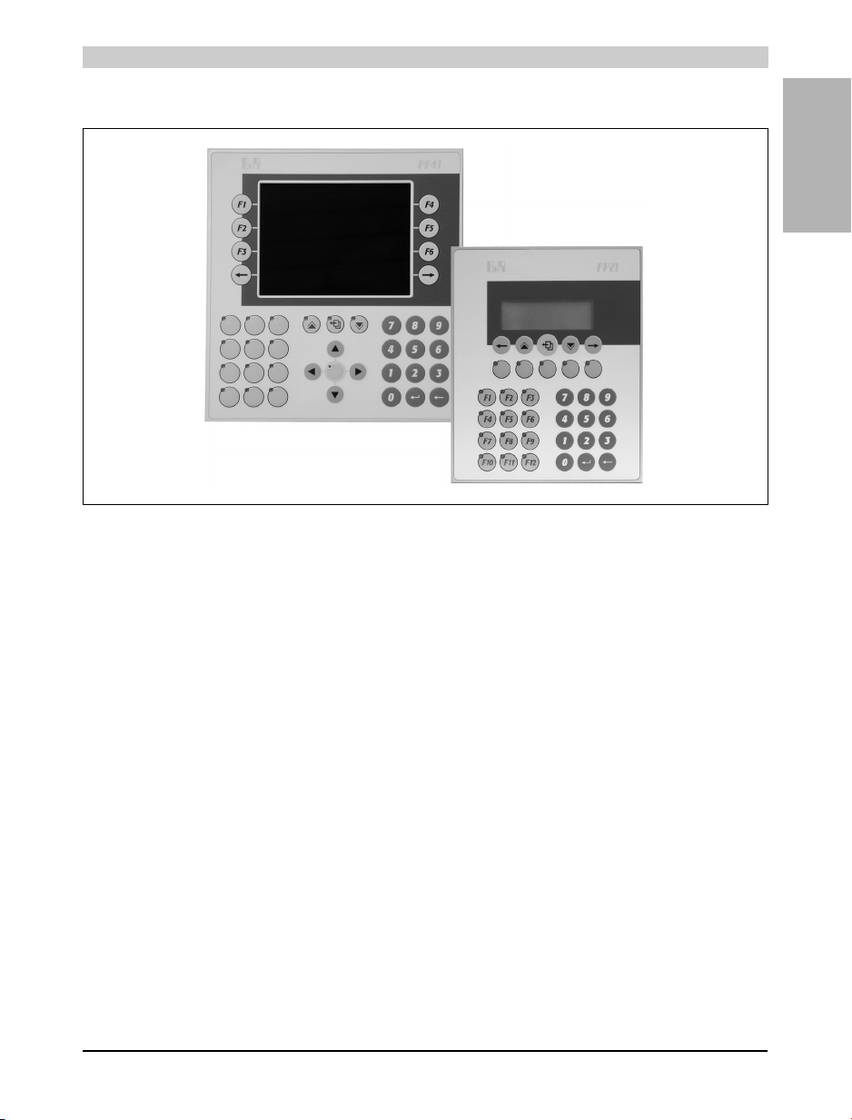
Figure 1: Power Panel
Power Panel • General Information
Chapter 1
Power Panel
Power Panel User's Manual 11
Page 12
Power Panel • Power Panel PP21
5. Power Panel PP21
5.1 Order Data
Model Number Short Description
Power Panel
4P0420.00-490
0AC201.9 Lithium batteries, 5 pcs., 3 V / 950 mAh, button cell
0MC111.9 PCMCIA memory card, 2MB FlashPROM
0MC211.9 PCMCIA memory card, 2MB SRAM
4A0035.00-000 Set of legend strips for 4P0420.00-490 (for 10 devices)
7TB712.9 Terminal block, 12 pin, screw clamps
7TB712.91 Terminal block, 12 pin, cage clamps
7TB712:90-02 Terminal block, 12 pin, 20 pcs., screw clamps
7TB712:91-02 Terminal block, 12 pin, 20 pcs., cage clamps
1) All parts required to install the Power Panel, including key legend sheets, are included in its delivery. The backup battery and the 4 pin
1)
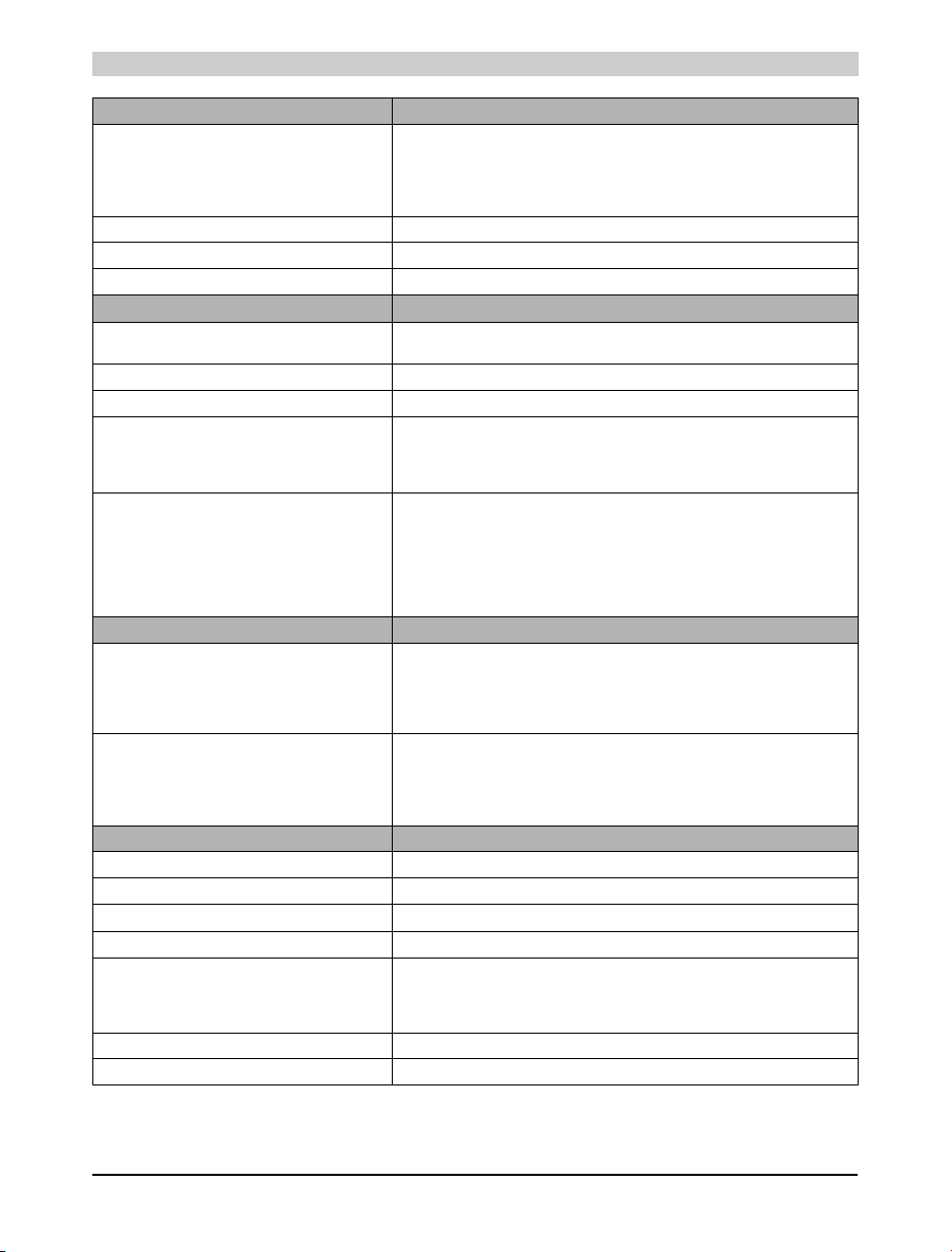
Power Panel PP21, LC display 4x20 characters, background lighting, 34 function keys,
system compatible 2003 CPU, 700Kb SRAM, 1.4MB FlashPROM, 1 PCMCIA slot, 1
RS232 interface, 1 CAN interface: electrically isolated, network capable, 6 slots for screwin modules, 10 digital inputs 24 VDC, 8 digital outputs 24 VDC, 0.4 A, IP65 protection (from
front), 155 x 190 mm (WxH), 24 VDC, Order TB712 terminal blocks separately!
Accessories
Table 3: Order data for the Power Panel PP21
terminal block for the supply are also included. Two 12 pin terminal blocks must be ordered separately.
12 Power Panel User's Manual
Page 13
5.2 Photo
5.3 Technical Data
Power Panel • Power Panel PP21
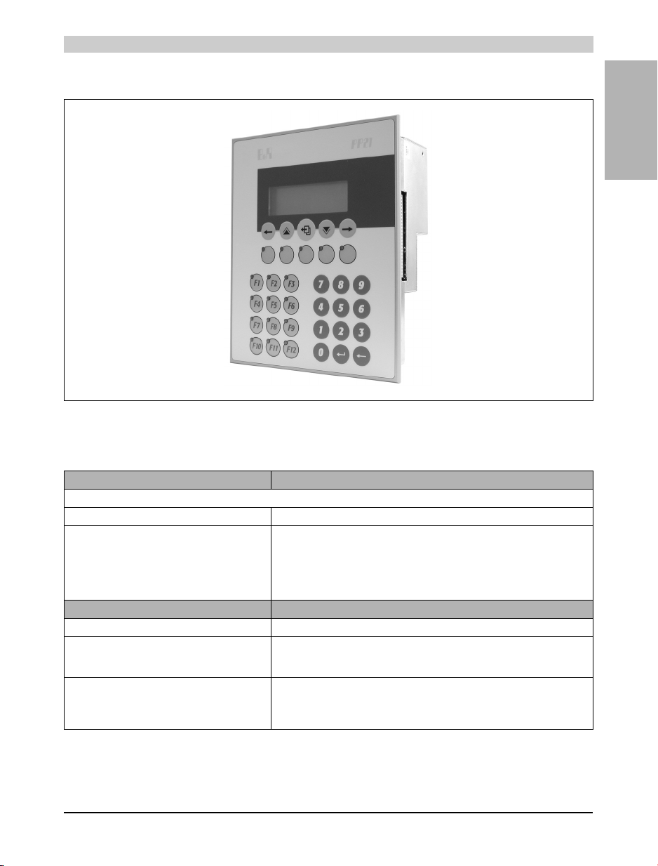
Figure 2: Power Panel PP21
Chapter 1
Power Panel
Product ID PP21
General Information
C-UL-US Listed In preparation
Standards
Temperature
Shock / Tests Carried Out
Vibration / Tests Carried Out
Emission / Tests Carried Out
Immunity / Tests Carried Out
Processor
Additional I/O Processor Handles I/O data points
Instruction Cycle Time
(Average value with 70% bit and
30% analog processing)
Standard Memory
User RAM
System PROM
User PROM
IEC61131-2 / IEC60068-2-x
IEC61131-2 / IEC60068-2-27
IEC61131-2 / IEC60068-2-6
EN50081-2 / EN55022+A1
IEC61131-2 / IEC61000-4-x
0.4 µs
700 Kbyte SRAM
600 KByte FlashPROM
1.4 MByte FlashPROM
Table 4: Technical data for PP21
Power Panel User's Manual 13
Page 14
Power Panel • Power Panel PP21
Product ID PP21
Data Buffering
Backup Battery
Buffer Current
Typical
Maximum
Hardware Watchdog Yes
Voltage Monitoring The internal supply is monitored for overvoltage and undervoltage
Fan No
Peripherals
Real-Time Clock
Resolution
Status Display LEDs
System Bus for Expansions No
Slots for B&R 2003 Screw-in Modules
Suitable for IF Modules (without CAN)
TPU Functionality Support
Suitable for CAN Communication
PCMCIA slot (See "PCMCIA Slot" on page 37.)
Standard
Card Height
Card Type
Memory Size
SRAM
FlashPROM
Standard Communication Interfaces
Application Interface IF1
Electrical Isolation
Design
Max. Distance
Max. Baud Rate
Application Interface IF2
Electrical Isolation
Design
Max. Distance
Max. Baud Rate
Digital Inputs
Number of Inputs 10
Inputs with Additional Functions (TPU) Inputs 1-4
Input Frequency (TPU) 50 kHz (Incremental encoder operation)
Wiring Sink
Input Voltage
Minimum
Nominal
Maximum
Input Current at Nominal Voltage Approx. 4 mA
Input Delay Max. 1 ms (not TPU)
Table 4: Technical data for PP21 (cont.)
Lithium battery 3 V / 950 mAh
10 µA
200 µA
Nonvolatile
1 sec
6
Slots 1-3
Slot 1 with interface module 4IF370.7
JEIDA V 4.0 or PCMCIA Standard Release 2.0
Slots 4-6
1
Max. 3 mm
Memory cards
Max. 4 MByte
Max. 4 MByte
RS232
No
9 pin DSUB plug
15 m / 19200 Baud
115.2 kBaud
CAN
Yes
9 pin DSUB plug
1,000 m
500 kBaud
18 VDC
24 VDC
30 VDC
14 Power Panel User's Manual
Page 15
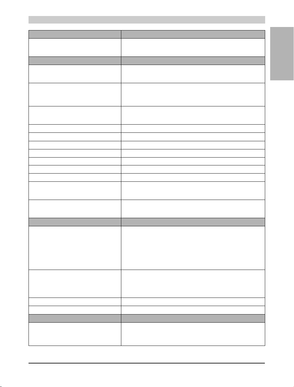
Power Panel • Power Panel PP21
Product ID PP21
Electrical Isolation
Input - PLC
Input - Outp ut
Digital Outputs
Amount/Type
Highside Driver IC (Transistor)
Potential-Free Relay Contact
Switching Voltage
Minimum
Nominal
Maximum
Continuous Current per
Output
Module
Load for Potential-Free Relay Contact Max. 0.5 A
Leakage Current when Switched Off 12 µA
Overload Protection Yes
Switching On after Overload Cutoff Automatically within seconds (depends on the panel temperature)
Continuous Short Circuit Current Typ. 4 A
Internal Protective Circuit Yes
Braking Voltage when Switching Off Inductive Loads 47 V
Switching Delay
Log. 0 - Log. 1
Log. 1 - Log. 0
Electrical Isolation
Output - PLC
Output - Input
HMI
Display
Type
Number of Lines
Number of Characters/Line
Character Height
Background Lighting
Character Set
Reading Angle
Keyboard
Number of Keys
Design
Function Keys
System Keys
Front Multi-layered front with insertion slots for key legends
Protection According to IEC 60529 IP65 (from front)
Power Supply
Input Voltage
Minimum
Nominal
Maximum
Covered keypad with metallic snap-action disks
17, with LEDs, labeled with legend sheets
17 (number block, control keys)
Table 4: Technical data for PP21 (cont.)
Yes
Yes
8
1
18 VDC
24 VDC
30 VDC
Max. 0.4 A
Max. 3.2 A
Max. 450 µs
Max. 450 µs
Yes
Yes
LC Display
4
20
4.75 mm
LED
English/Katakana
Approx. 60 °
34 membrane keys
18 VDC
24 VDC
30 VDC
Chapter 1
Power Panel
Power Panel User's Manual 15
Page 16
Power Panel • Power Panel PP21
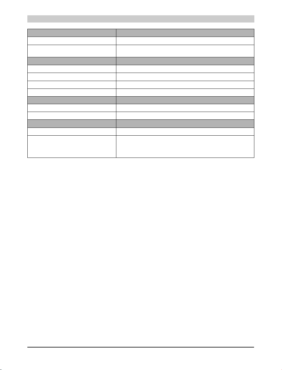
Product ID PP21
Power Consumption Max. 20 W
Output Power for Screw-in Modules and
PCMCIA Interface
Operational Conditions
Installation Vertical, ±45°
Altitude Max. 3,000 m
Environment Temperature during Operation 0 to 50 °C
Relative Humidity during Operation 10 to 90% (non-condensing)
Storage Conditions
Storage Temperature -20 to 60 °C
Relative Humidity for Storage 5 to 95 % (non-condensing)
Mechanical Characteristics
Weight Approx. 1.25 kg
Dimensions
Width
Height
Depth
Table 4: Technical data for PP21 (cont.)
10 W
155 mm
190 mm
84.4 mm
16 Power Panel User's Manual
Page 17
5.4 Images
Power Panel • Power Panel PP21
Chapter 1
Power Panel
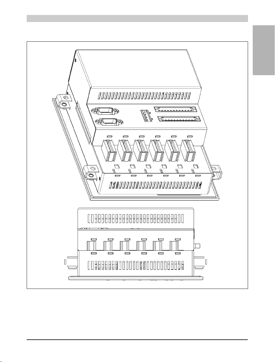
Figure 3: PP21
Power Panel User's Manual 17
Page 18
Power Panel • Power Panel PP21
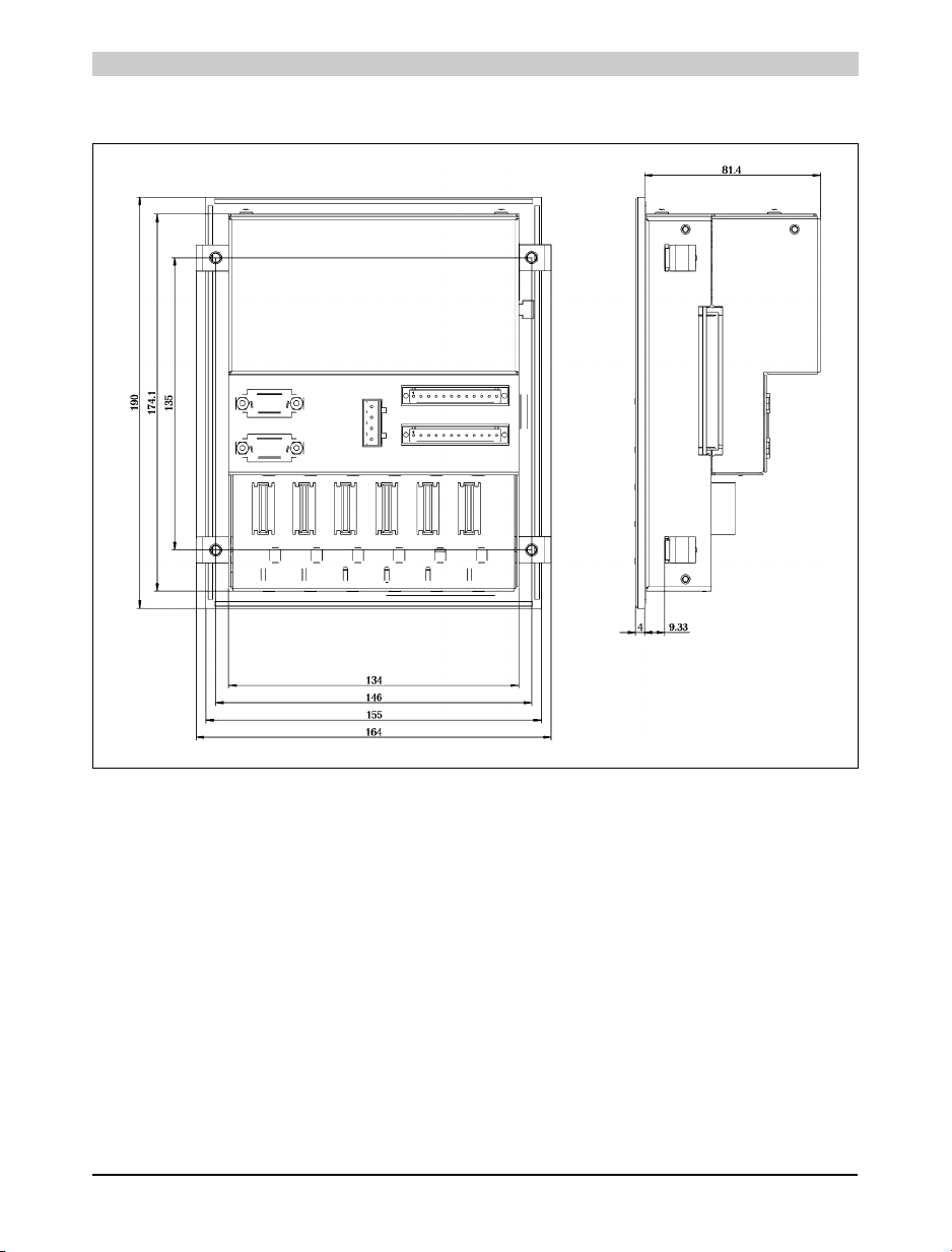
5.5 Dimensions
Figure 4: PP21 dimensions
18 Power Panel User's Manual
Page 19
Power Panel • Power Panel PP41
6. Power Panel PP41
6.1 Order Data
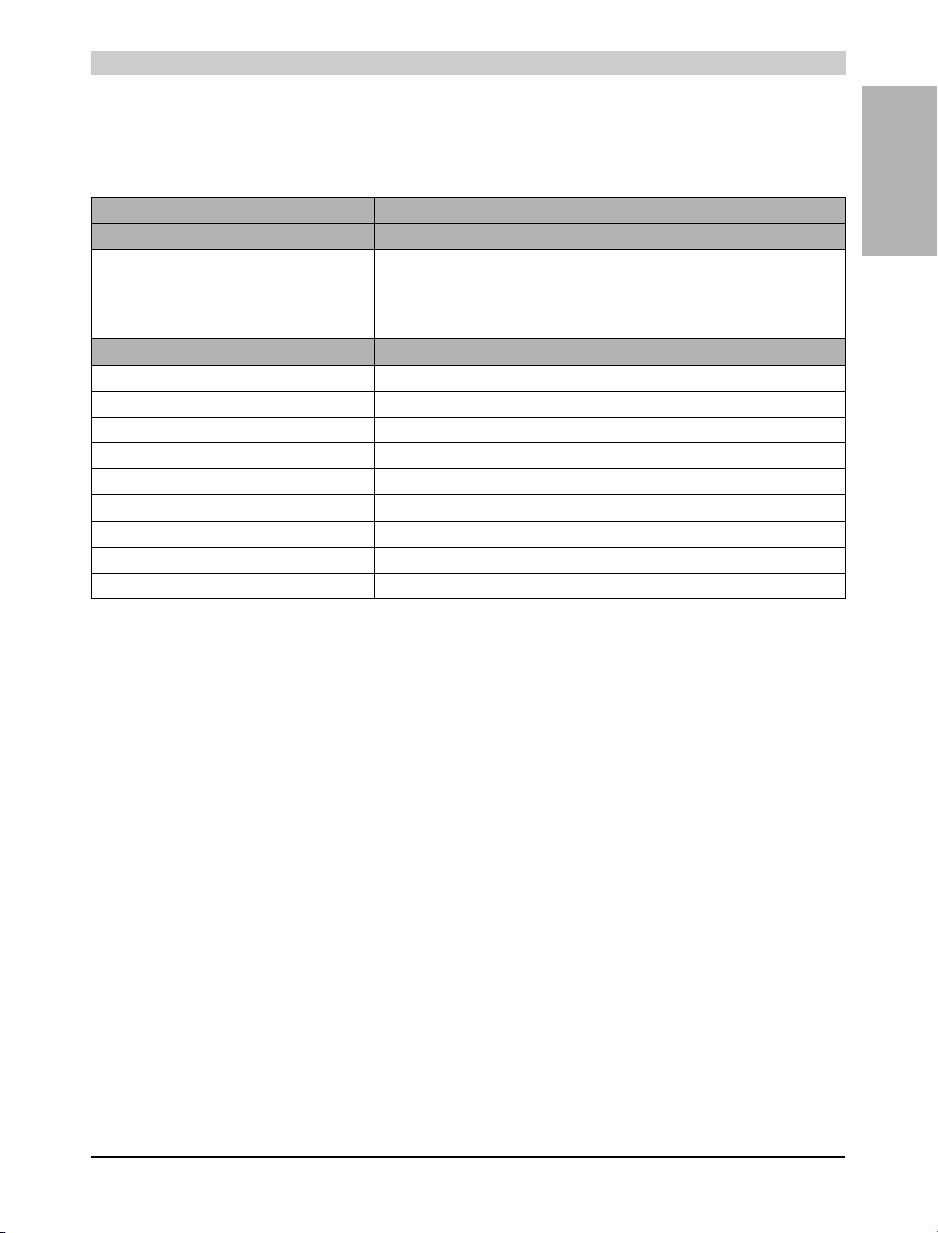
Model Number Short Description
Power Panel
4P3040.00-490
0AC201.9 Lithium batteries, 5 pcs., 3 V / 950 mAh, button cell
0MC111.9 PCMCIA memory card, 2MB FlashPROM
0MC211.9 PCMCIA memory card, 2MB SRAM
4A0034.00-000 Set of legend strips for 4P3040.00-490 (für 10 Geräte)
4EX101.00 Power Panel expansion for PP41, 1 insert slot for interface module inserts
7TB712.9 Terminal block, 12 pin, screw clamps
7TB712.91 Terminal block, 12 pin, cage clamps
7TB712:90-02 Terminal block, 12 pin, 20 pcs., screw clamps
7TB712:91-02 Terminal block, 12 pin, 20 pcs., cage clamps
1)
Power Panel PP41, 5.7 inch QVGA black/white LC display, 8 softkeys and 32 function keys,
system compatible 2003 CPU, 700 KB SRAM, 1.4 MB FlashPROM, 1 PCMCIA slot, 1
RS232 interface, 1 CAN interface: electrically isolated, network capable, 6 slots for screwin modules, 10 digital inputs 24 VDC, 8 digital outputs 24 VDC, 0.4 A, IP65 protection (from
front), 205 x 220 mm (WxH), 24 VDC, Order TB712 terminal blocks separately!
Accessories
Table 5: Order data for PP41
Chapter 1
Power Panel
1) All parts required to install the Power Panel, including key legend sheets, are included in its delivery. The backup battery and the 4 pin
terminal block for the supply are also included. Two 12 pin terminal blocks must be ordered separately.
Power Panel User's Manual 19
Page 20
Power Panel • Power Panel PP41
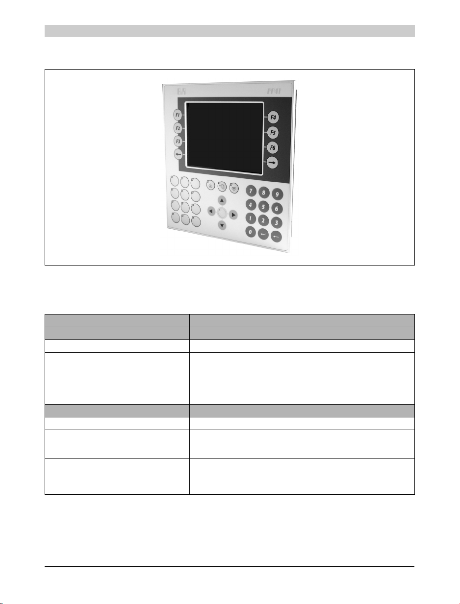
6.2 Photo
6.3 Technical Data
Figure 5: PP41
Product ID PP41
General Information
C-UL-US Listed In preparation
Standards
Temperature
Shock / Tests Carried Out
Vibration / Tests Carried Out
Emission / Tests Carried Out
Immunity / Tests Carried Out
Processor
Additional I/O Processor Handles I/O data points
Instruction Cycle Time
(Average value with 70% bit and
30% analog processing)
Standard Memory
User RAM
System PROM
User PROM
IEC61131-2 / IEC60068-2-x
IEC61131-2 / IEC60068-2-27
IEC61131-2 / IEC60068-2-6
EN50081-2 / EN55022+A1
IEC61131-2 / IEC61000-4-x
0.4 µs
700 Kbyte SRAM
600 KByte FlashPROM
1.4 MByte FlashPROM
Table 6: Technical data for PP41
20 Power Panel User's Manual
Page 21
Power Panel • Power Panel PP41
Product ID PP41
Data Buffering
Backup Battery
Buffer Current
Typical
Maximum
Hardware Watchdog Yes
Voltage Monitoring The internal supply is monitored for overvoltage and undervoltage
Fan No
Peripherals
Real-Time Clock
Resolution
Status Display LEDs
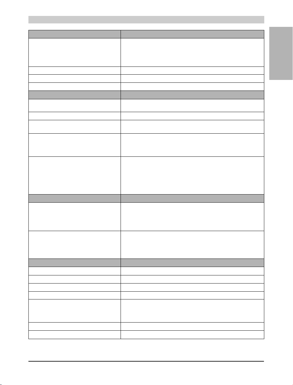
System Bus for Expansions Expansion module EX101
Slots for B&R 2003 Screw-in Modules
Suitable for IF Modules (without CAN)
TPU Functionality Support
Suitable for CAN Communication
PCMCIA slot (See "PCMCIA Slot" on page 37.)
Standard
Card Height
Card Type
Memory Size
SRAM
FlashPROM
Standard Communication Interfaces
Application Interface IF1
Electrical Isolation
Design
Max. Distance
Max. Baud Rate
Application Interface IF2
Electrical Isolation
Design
Max. Distance
Max. Baud Rate
Digital Inputs
Number of Inputs 10
Inputs with Additional Functions (TPU) Inputs 1-4
Input Frequency (TPU) 50 kHz (Incremental encoder operation)
Wiring Sink
Input Voltage
Minimum
Nominal
Maximum
Input Current at Nominal Voltage Approx. 4 mA
Input Delay Max. 1 ms (not TPU)
Insert slot for B&R SYSTEM 2005 interface module inserts
Table 6: Technical data for PP41 (cont.)
Lithium battery 3 V / 950 mAh
10 µA
200 µA
Nonvolatile
1 sec
6
Slots 1-3
Slot 1 with interface module 4IF370.7
JEIDA V 4.0 or PCMCIA Standard Release 2.0
Slots 4-6
1
Max. 3 mm
Memory cards
Max. 4 MByte
Max. 4 MByte
RS232
No
9 pin DSUB plug
15 m / 19200 Baud
115.2 kBaud
CAN
Yes
9 pin DSUB plug
1,000 m
500 kBaud
18 VDC
24 VDC
30 VDC
Chapter 1
Power Panel
Power Panel User's Manual 21
Page 22
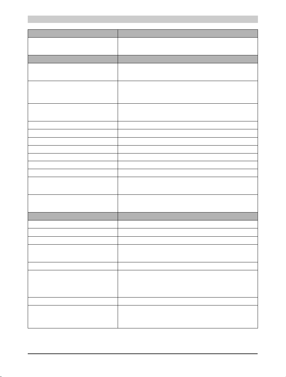
Power Panel • Power Panel PP41
Product ID PP41
Electrical Isolation
Input - PLC
Input - Outp ut
Digital Outputs
Amount/Type
Highside Driver IC (Transistor)
Potential-Free Relay Contact
Switching Voltage
Minimum
Nominal
Maximum
Continuous Current per
Output
Module
Load for Potential-Free Relay Contact Max. 0.5 A
Leakage Current when Switched Off 12 µA
Overload Protection Yes
Switching On after Overload Cutoff Automatically within seconds (depends on the panel temperature)
Continuous Short Circuit Current Typ. 4 A
Internal Protective Circuit Yes
Braking Voltage when Switching Off Inductive Loads 47 V
Switching Delay
Log. 0 - Log. 1
Log. 1 - Log. 0
Electrical Isolation
Output - PLC
Output - Input
HMI
Display Type LCD B/W
Resolution QVGA (320 x 240 pixels)
Display Diagonal 5.7" (145 mm)
Background Lighting
Brightness
1) 2)
Lifespan
Reading Angle Approx. 35°
Keyboard
Number of Keys
Design
Function Keys
System Keys
Front Multi-layered front with insertion slots for key legends
Protection According to IEC 60529 IP65 (from front)
Covered keypad with metallic snap-action disks
16, with LEDs, labeled with legend sheets
24 (number block, cursor block, control keys)
Yes
Yes
8
1
18 VDC
24 VDC
30 VDC
Max. 0.4 A
Max. 3.2 A
Max. 450 µs
Max. 450 µs
Yes
Yes
150 cd/m²
20000 h
40 membrane keys
Table 6: Technical data for PP41 (cont.)
22 Power Panel User's Manual
Page 23
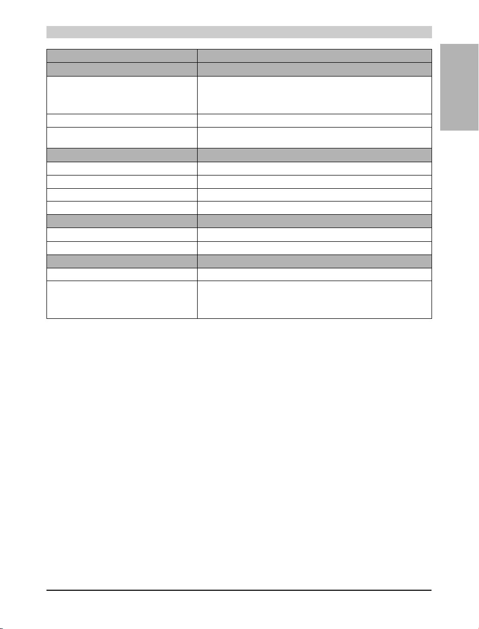
Power Panel • Power Panel PP41
Product ID PP41
Power Supply
Input Voltage
Minimum
Nominal
Maximum
Power Consumption Max. 20 W
Output Power for Screw-in Modules and
PCMCIA Interface
Operational Conditions
Installation Vertical, ±45°
Altitude Max. 3,000 m
Environmental Temperature during Operation
Relative Humidity during Operation 10 to 90% (non-condensing)
Storage Conditions
Storage Temperature -20 to 60 °C
Relative Humidity for Storage 5 to 95 % (non-condensing)
Mechanical Characteristics
Weight Approx. 1.95 kg
Dimensions
Width
Height
Depth
3)
Table 6: Technical data for PP41 (cont.)
18 VDC
24 VDC
30 VDC
11 W
0 to 50 °C
205 mm
220 mm
110.4 mm
Chapter 1
Power Panel
1) 25 °C environmental temperature.
2) Brightness reduced to 50 %.
3) Depending on installation.
Power Panel User's Manual 23
Page 24
Power Panel • Power Panel PP41
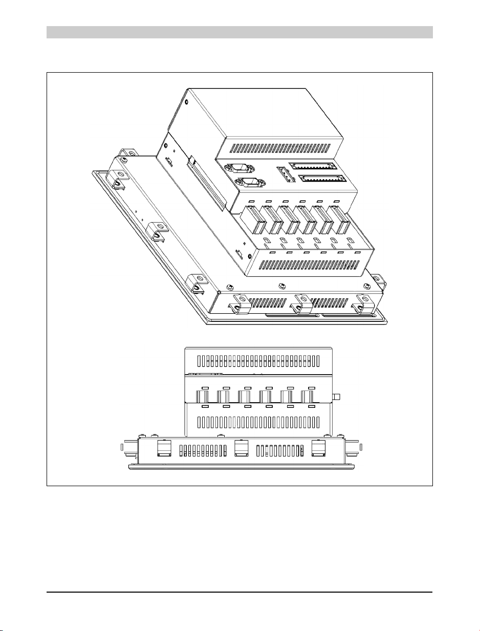
6.4 Images
Figure 6: PP41
24 Power Panel User's Manual
Page 25
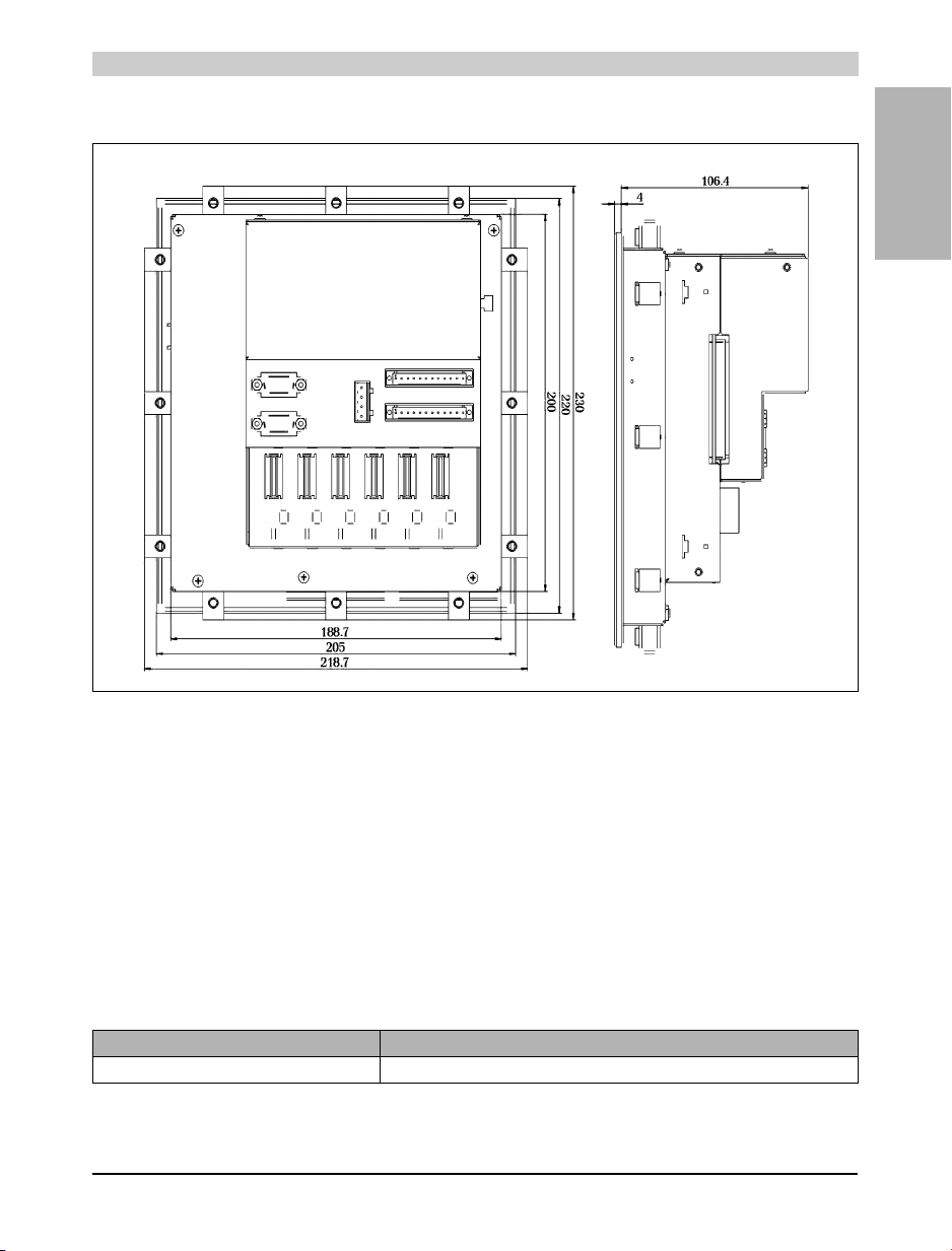
6.5 Dimensions
Power Panel • Power Panel Expansion EX101 Module
Chapter 1
Power Panel
Figure 7: PP41 dimensions
7. Power Panel Expansion EX101 Module
7.1 General Information
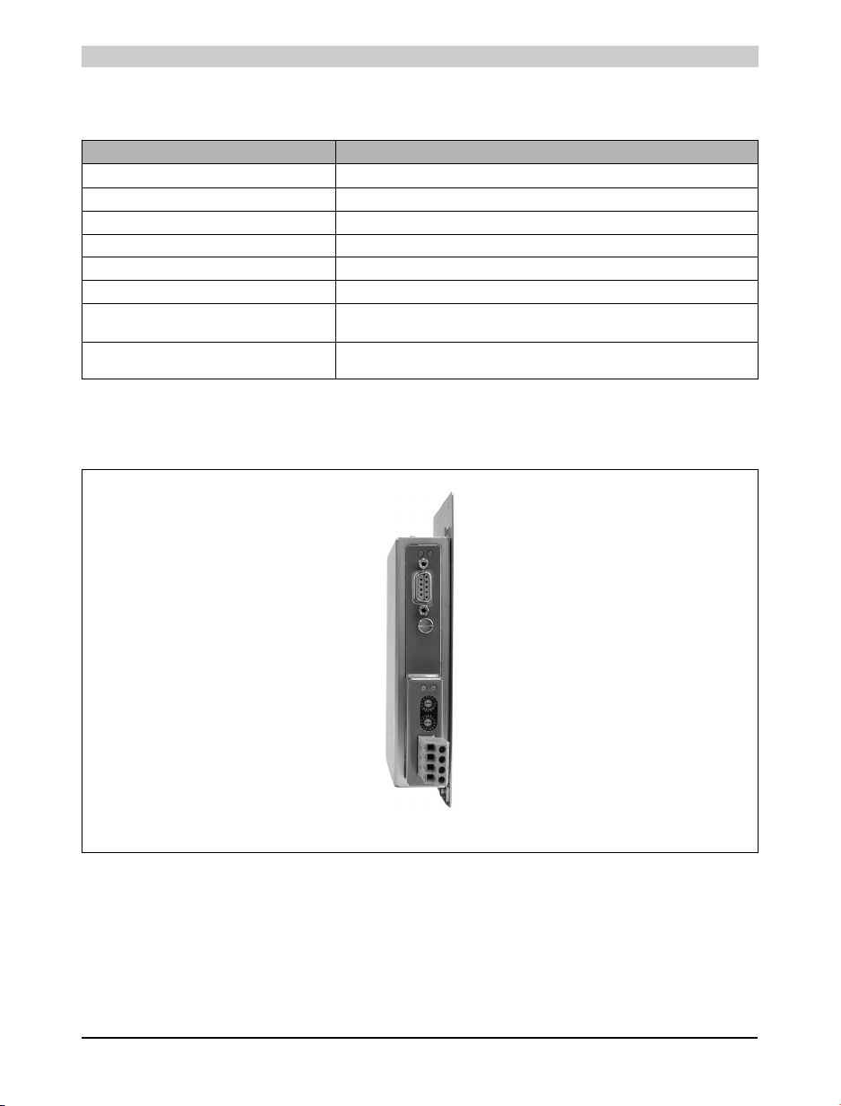
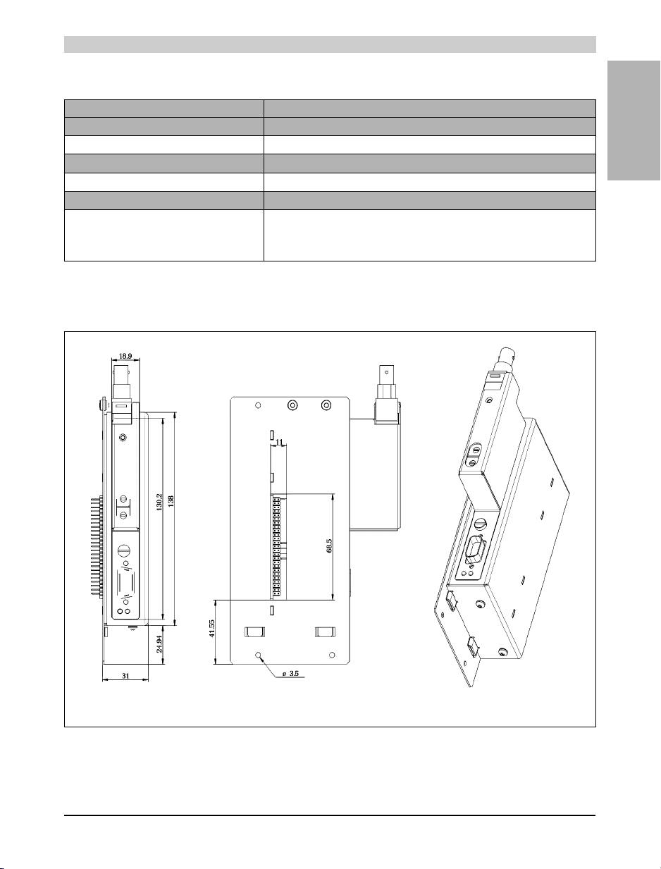
The expansion module EX101 can be installed on the Power Panel PP41. B&R SYSTEMS 2005
interface module inserts can be operated in the EX101 insert slot.
A description for interface module inserts can be found in the "B&R SYSTEM 2005 User's
Manual" (model no.: MASYS22005-E).
7.2 Order Data
Model Number Short Description
4EX101.00 Power Panel expansion for PP41, 1 insert slot for interface module inserts
Table 7: Order data for EX101
Power Panel User's Manual 25
Page 26
Power Panel • Power Panel Expansion EX101 Module
The following B&R SYSTEM 2005 interface module inserts can be operated with the EX101
module:
Model Number Short Description
3IF613.9 Three RS232 interfaces
3IF621.9 One RS485/RS422 interface and one CAN interface
3IF622.9 One RS232 interface and two RS485/RS422 interfaces
3IF661.9 One RS485 interface (PROFIBUS-DP Slave)
3IF671.9 One RS232 interface, one RS485/RS422 interface and one CAN interface
3IF672.9 One RS232 interface and two CAN interfaces
3IF681.95 One RS232 interface and one ETHERNET interface with 10 BASE2 connection
3IF681.96 One RS232 interface and one ETHERNET interface with 10 BASE-T connection (Twisted
(CHEAPERNET BNC socket)
Pair / RJ45 socket)
Table 8: Interface modules that can be operated in the EX101
7.3 Photo
The IF621 interface module insert shown in the picture is not included in the delivery
Figure 8: EX101
26 Power Panel User's Manual
Page 27
Power Panel • Power Panel Expansion EX101 Module
7.4 Technical Data
Product ID EX101
General Information
Module Type Power Panel expansion for PP41
Peripherals
Insert Slots 1 (for interface module inserts)
Mechanical Characteristics
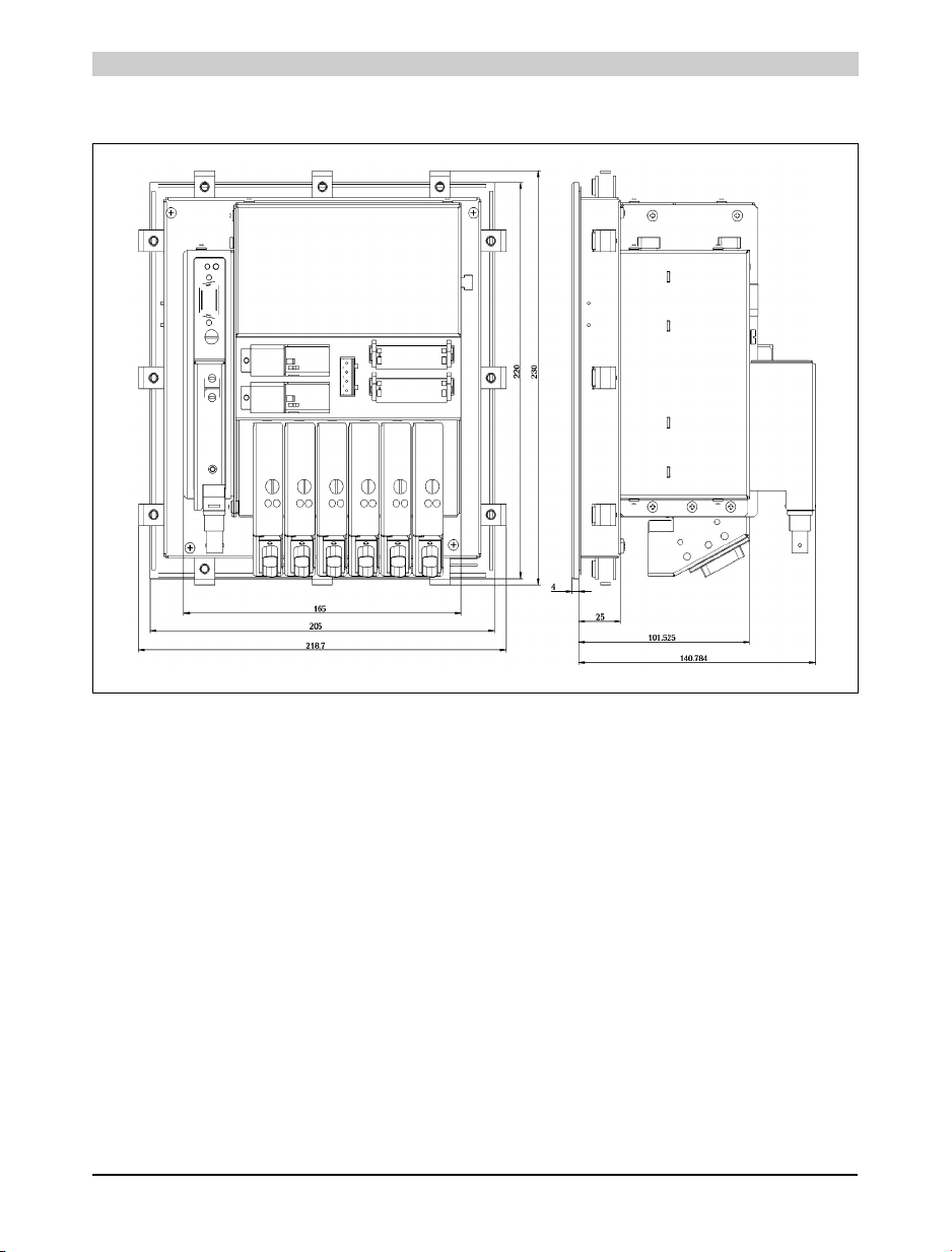
Dimensions
Width
Height
Depth
31 mm
173 mm
81.4 mm
Table 9: Technical data for EX101
7.5 Images
Chapter 1
Power Panel
View from above View from below
Figure 9: EX101
Power Panel User's Manual 27
Page 28
Power Panel • Power Panel Expansion EX101 Module
7.6 Dimensions
Figure 10: EX101 dimensions
28 Power Panel User's Manual
Page 29
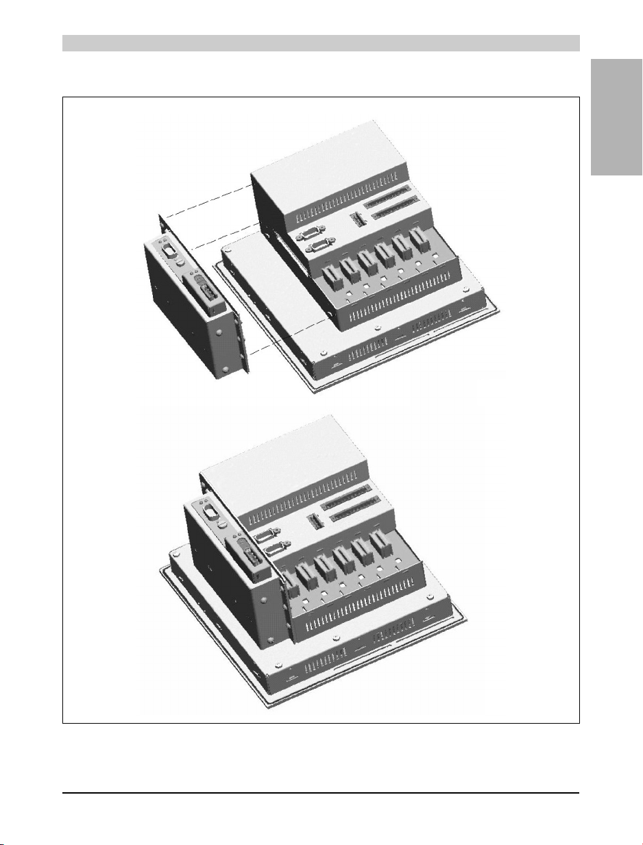
7.7 Installation
Power Panel • Power Panel Expansion EX101 Module
Chapter 1
Power Panel
Figure 11: EX101 installation
Power Panel User's Manual 29
Page 30
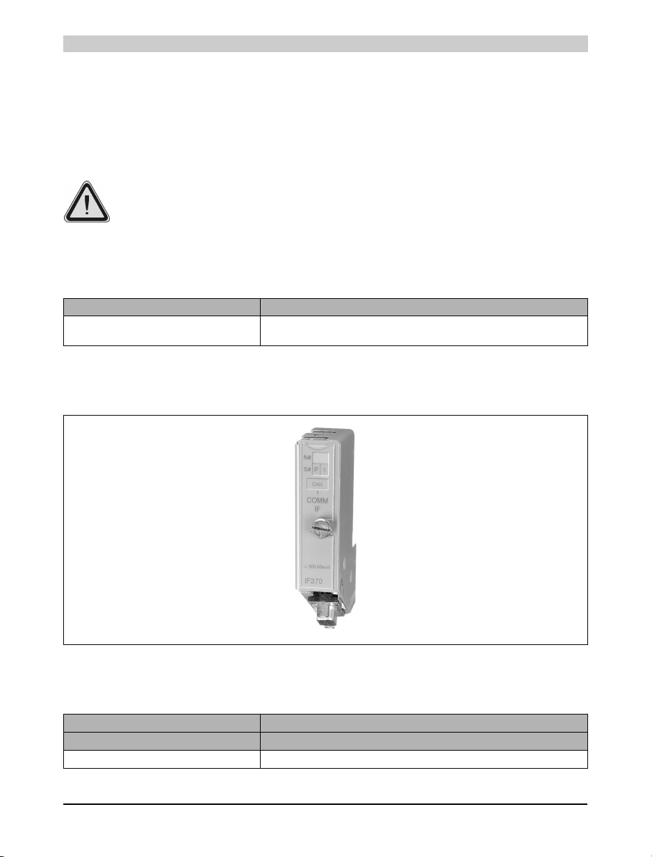
Power Panel • IF370 CAN Interface Module
8. IF370 CAN Interface Module
8.1 General Information
The IF370 interface module is used for connecting the B&R Power Panel to a CAN network. It
must always be operated in slot 1.
The IF370 interface module is only suitable for operating with a B&R Power Panel. It
should never be operated in a B&R SYSTEM 2003 module.
8.2 Order Data
Model Number Short Description
4IF370.7 Power Panel interface module, 1 CAN interface, electrically isolated, network capable,
8.3 Photo
screw-in module
Table 10: Order data for the IF370
Figure 12: IF370
8.4 Technical Data
Product ID IF370
General Information
C-UL-US Listed In preparation
Table 11: Technical data for the IF370
30 Power Panel User's Manual
Page 31
Power Panel • IF370 CAN Interface Module
Product ID IF370
B&R ID Code $44
Module Type B&R Power Panel screw-in module
Slot Power Panel interface, slot 1
Power Consumption TBD
Standard Communication Interface
Interface Type CAN
Electrical Isolation Interface - Power Panel
Design 9 pin DSUB plug
Status Display 2 Status LEDs
Maximum Distance 1,000 m
Maximum Baud Rate
Bus Length 10 - 60 m
Bus Length 100 -200 m
Bus Length 800 -1,000 m
Network Capable Yes
Mechanical Characteristics
Dimensions B&R Power Panel screw-in module
Max. 500 kBit/s
Max. 250 kBit/s
Max. 50 kBit/s
Table 11: Technical data for the IF370
8.5 Status LEDs
Lit LEDs Description
Yellow / Green Data is being sent
Green Data is being received
Table 12: IF370 status LEDs
Chapter 1
Power Panel
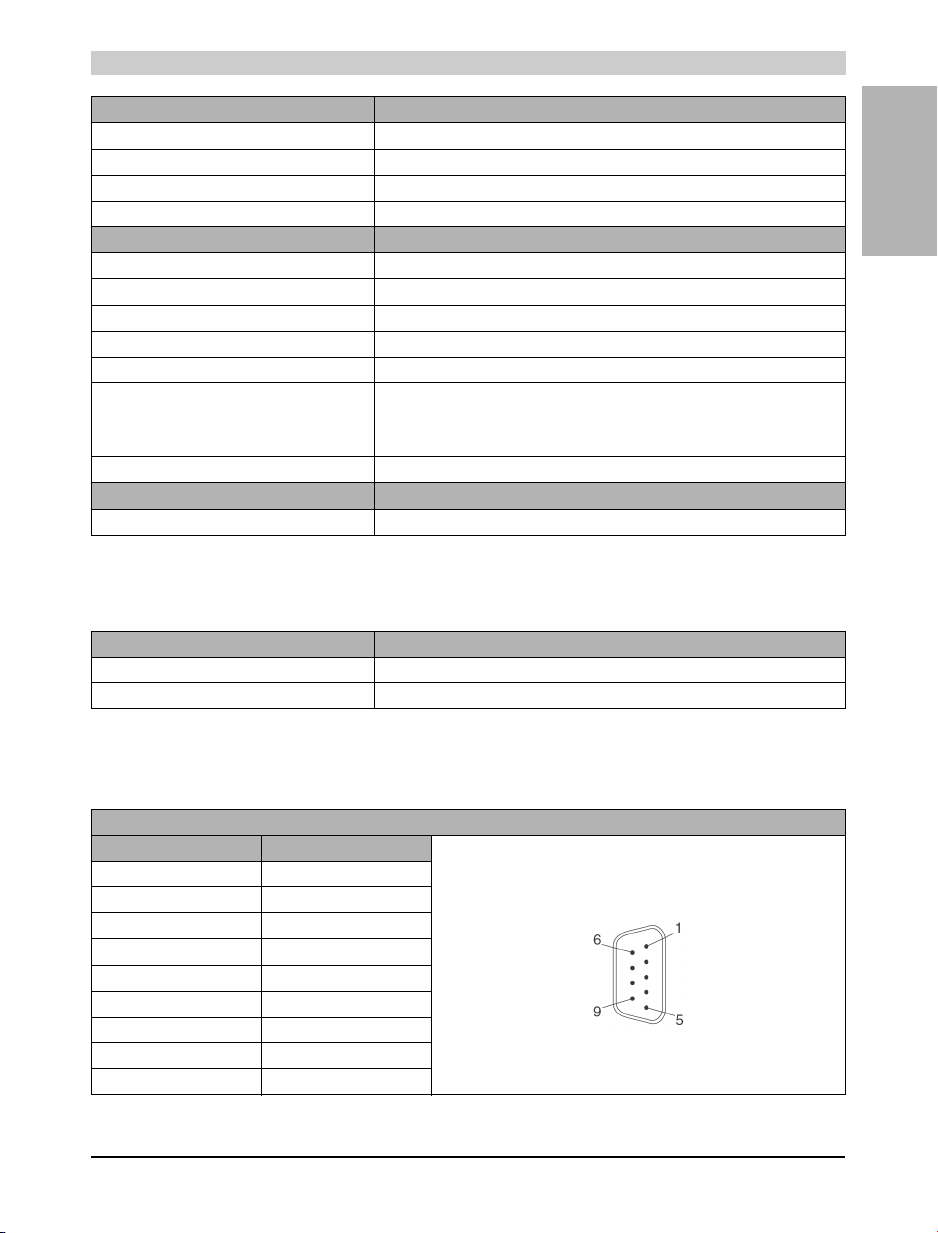
8.6 Pin Assignments
Pin Assignment for CAN interface
Pin Assignment
1NC
2CAN_L
3CAN_GND
4NC
5NC
6Reserved
7CAN_H
8NC
9NC
Table 13: Pin assignments for the IF370 CAN interface
Power Panel User's Manual 31
9 pin DSUB connector
Page 32
Power Panel • Mounting Instructions
9. Mounting Instructions
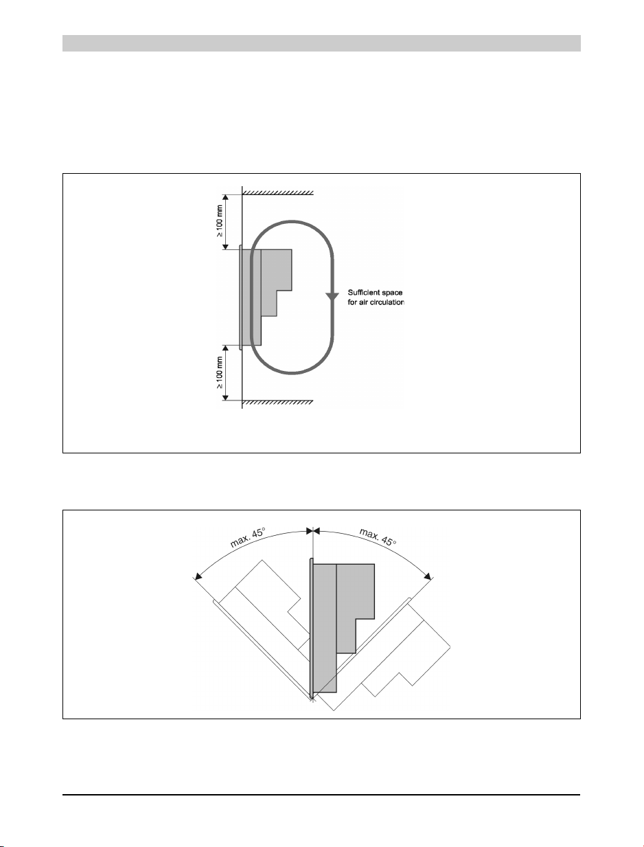
• The Power Panel should be mounted with the four retaining clips (two left and right
which are supplied in the delivery.
• In order to guarantee proper air circulation, allow a distance of at least 10 cm (above and
below) between the ventilation slots and all other objects.
Figure 13: Sufficient space for air circulation
• The Power Panel can be mounted up to a maximum angle of 45°.
Figure 14: Mounting angle
32 Power Panel User's Manual
Page 33
Power Panel • Device Label
10. Device Label
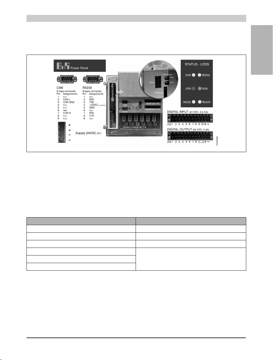
The assignment for the plugs and the pin connectors are indicated on the device label.
Figure 15: Device label
11. Programming
Chapter 1
Power Panel
11.1 Programming the PLC CPU
Programming the PLC CPU is done using Automation Studio™ or PG2000. Several
programming languages are available.
Automation Studio™ PG2000
Automation Basic (previously PL2000) Instruction List (IL)
ANSI C Ladder Diagram (LAD)
IEC 1131 Ladder Diagram (LAD) PL2000 High Level Language (structured text)
IEC 1131 Sequential Function Chart (SFC)
IEC 1131 Structured Text (ST)
IEC 1131 Instruction List (IL)
Table 14: Programming languages
11.2 Visualization
The visualization application is created using B&R Automation Studio™.
Power Panel User's Manual 33
Page 34
Power Panel • Description of Components
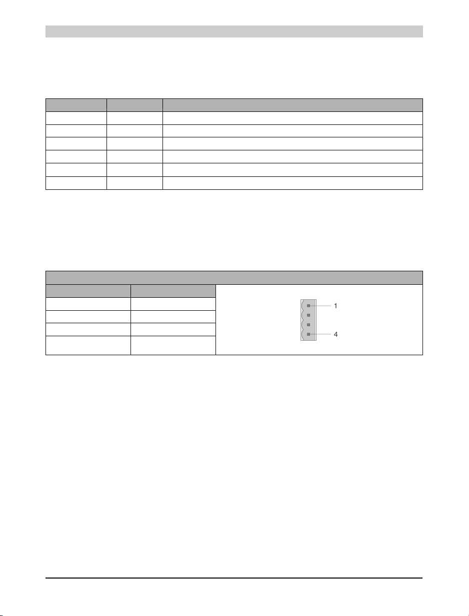
12. Description of Components
12.1 Status LEDs
LED Color Meaning
CAN Yellow Data transfer to or from CAN controller
RS232 Yellow Indicates if data is being transmitted or received
ERR Red Lit in Service mode
RUN Green Lit in RUN and in Service mode
MODE Yellow Lit when programming FlashPROM
READY Yellow Lit in Service mode
Table 15: Status LEDs
12.2 Power Supply
The Power Panel is equipped with a 24 VDC power supply. The pin assignment is printed on the
housing.
Power Supply for Pin Assignment
Pin Description
1+
2+
3-
4-
Table 16: Power supply for pin assignment
Both "+" and "-" pins are connected to each other internally
34 Power Panel User's Manual
Page 35
Power Panel • Description of Components
12.3 Interfaces
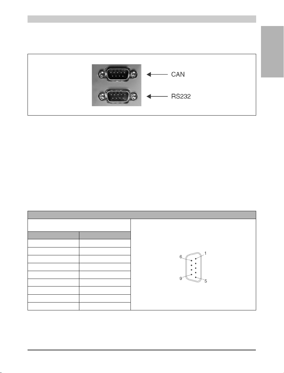
The Power Panel has two interfaces:
Figure 16: Interfaces
12.3.1 CAN Interface
The electrically isolated standard fieldbus interface is used for the following tasks:
• Communication with other control systems
• Decentralization and remote I/O expansion using B&R 2003 components and a CAN bus
controller
We recommend using the AC911 T-connector for coupling to a CAN network. A terminal
resistance is integrated into the T-connector for the bus termination, which can be switched on
or off. For more information on wiring CAN fieldbus systems, see chapter 2, "Installation", section
"CAN Fieldbus" in the B&R SYSTEM 2003 User's Manual.
Chapter 1
Power Panel
Pin Assignment for CAN Interface
Electrically isolated
Assignment According to CiA DS 102-1
Pin Assignment
1n. c.
2CAN_L
3CAN_GND
4n. c.
5n. c.
6Reserved
7CAN_H
8n. c.
9n. c.
Table 17: Pin assignment for CAN interface
9 pin DSUB plug
Power Panel User's Manual 35
Page 36
Power Panel • Description of Components
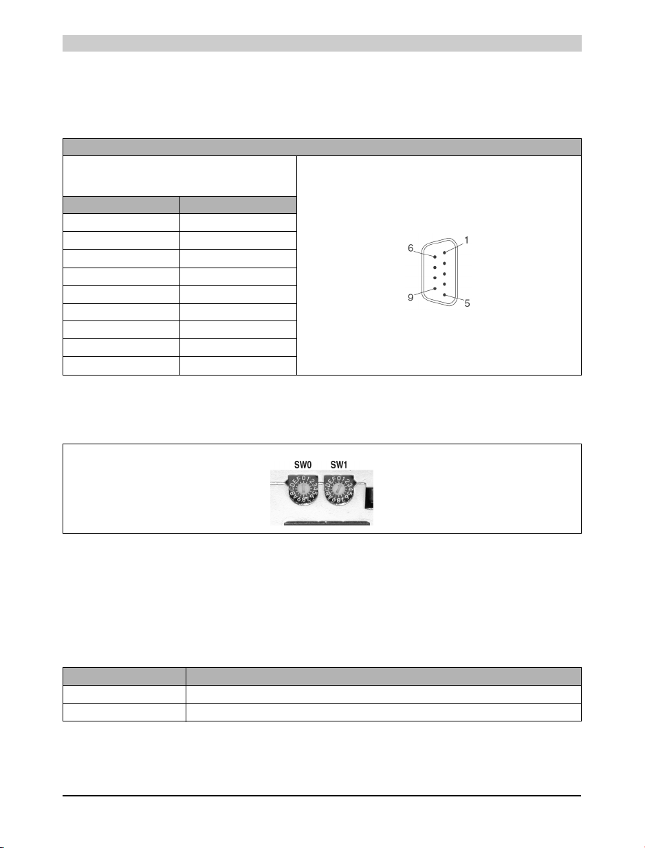
12.3.2 RS232 Interface
This non-electrically isolated interface is primarily intended for programming the CPU. The
RS232 can also be used as a general interface (e.g. printer, bar code reader, etc.).
Pin Assignment for RS232 Interface
RS232 Interface
Not electrically
isolated up to 115 kBaud
Pin Assignment
1CTS
2RXD
3TXD
4 +5 VDC /max. 500 mA
5GND
6n. c.
7RTS
8CTS
9GND
9 pin DSUB connector
Table 18: Pin assignment RS232 interface
12.4 Operating Mode Switch
Figure 17: Operating mode switch
The Power Panels are equipped with 2 hex switches, which are used as an operating mode
switch. Switch positions 01 - FC are available for any purpose in an application. The switch's
position can be evaluated from an application program. The operating system only interprets the
switch position when switched on.
All other switch positions are reserved for special functions.
Switch Position Description
00 Programming System Flash (see respective section)
01 - FC Freely available for use in an application (e.g. CAN node number)
Table 19: Switch settings for the MODE switch
36 Power Panel User's Manual
Page 37

Power Panel • Description of Components
Switch Position Description
FD This setting should not to be used.
FE Reserved for B&R expansions – these settings are not allowed to be used!
FF Diagnosis Mode
Update Mode - In this switch position, the Power Panel checks if an update memory card is inserted. If no card
is inserted, the Power Panel goes into SERVICE mode. Otherwise (depending on the Update configuration) the
operating system and/or the user-ROM for the Power Panel is cleared and reinstalled from the memory card. If
an error occurs during the installation, the red ERROR LED blinks. When no errors have occurred during
installation the green READY LED and the yellow RUN LED blink.
Table 19: Switch settings for the MODE switch
12.5 Programming System Flash
The Power Panel is delivered without an operating system installed. An operating system can be
downloaded or updated using the programming software. Installation of the operating system is
possible with both programming systems. When carrying out operating system download for the
first time using B&R Automation Studio™ , the steps below must be taken:
1) Switch off power supply to the PLC.
2) Set the MODE switch to 00.
3) Switch on the power supply again.
4) Make on-line connection to PC (physcially).
5) Start B&R Automation Studio™ ("OFFLINE" is displayed in the status bar)
Chapter 1
Power Panel
6) Select menu item "PROJECT" - "SERVICES" - "TRANSFER OPERATING SYSTEM"
7) A window named "Operating System Transfer" opens
8) The COM port can be changed in this window, if required. Only in this case (using the "Try
to connect Bootstraploader" button) must the connection be reestablished. If several PLC
sofware versions are available, these can also be selected.
9) By clicking on "Next" in the new window CAN bus specific settings can be made.
12.6 PCMCIA Slot
The Power Panels are equipped with one PCMCIA interface for B&R memory cards. PCMCIA
memory cards conforming to JEIDA V4.0 Type I or PCMCIA Standard Release 2.0 (max. 3 mm
high) are supported.
The memory on the PCMCIA card can be used with all types of B&R modules. Executable
programmes (Task) should not be stored on the PCMCIA card, because accessing the card
takes considerably longer than accessing the Power Panel's onboard memory.
Power Panel User's Manual 37
Page 38
Power Panel • Description of Components
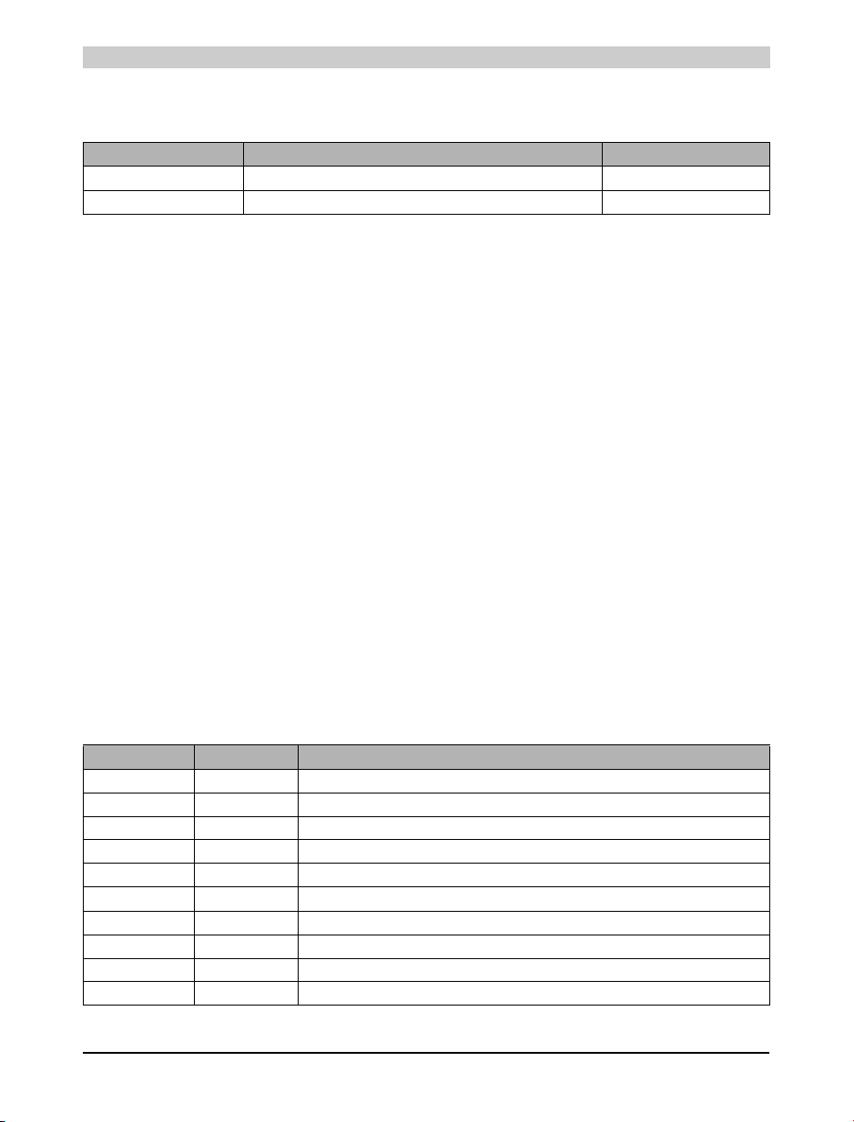
The Power Panel supports memory cards with up to 4 MByte SRAM or with up to 4 MByte
FlashPROM. The following memory card can be ordered from B&R:
Model Number Sh ort Description Power Consumption
0MC111.9 PCMCIA memory card, 2MB FlashPROM Max. 0.8 W
0MC211.9 PCMCIA memory card, 2MB SRAM Max. 0.8 W
The memory cards are used by the Power Panel as ROM Type "MEMCARD".
12.6.1 Limitations when using Memory Cards
Access of memory cards is very slow.
• Internal variables cannot be stored on the memory card
• Memory cannot be allocated on the memory cards
The SRAM and FlashPROM memory cards can only be written to by the Power Panel. Therefore
it is not possible to program system software or the application on a memory card directly on a
PC with a PCMCIA interface.
12.7 Power Panel Interface
The Power Panel is equipped with six slots for B&R SYSTEM 2003 screw-in modules. The
required screw-in modules are inserted into the Power Panel interface and screwed firmly into
place. The screw-in interface modules can be operated in slots 1 - 3. Screw-in modules can be
used in slots 4 - 6, which possess TPU functionality. The first slot has a second CAN port and
allows a second CAN interface by using a IF370 module.
12.8 Screw-in Module Overview
A description of the B&R SYSTEM 2003 screw-in module can be found in the "B&R SYSTEM
2003 User's Manual " (model. no.: MASYS22003-E).
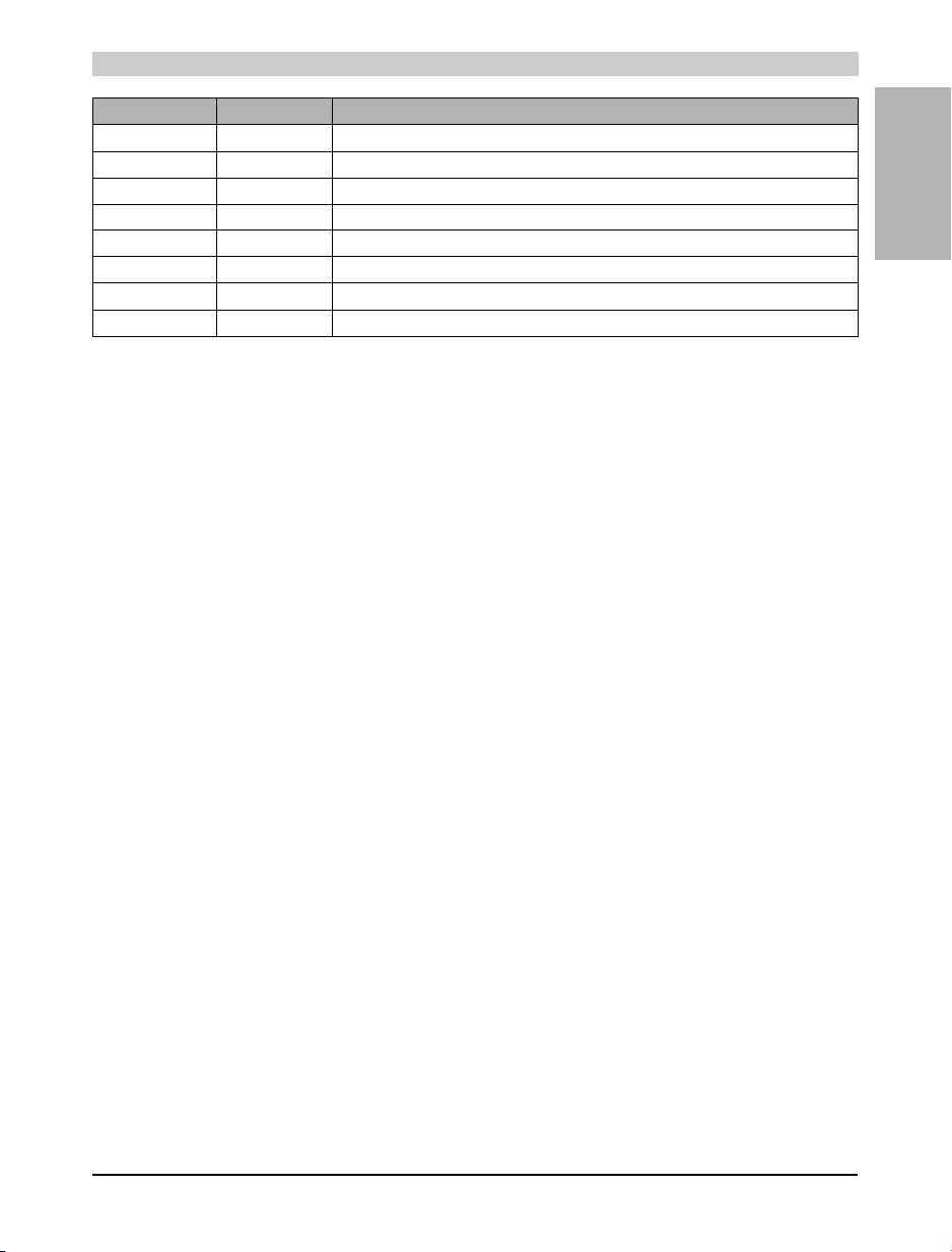
Module Type Description
7AI261.7 Analog IN 1 input used to evaluate a full-bridge strain gauge
7AI351.70 Analog IN 1 x ±10 V or 1 x 0 - 20 mA (1 x ±20 mA also possible), potentiometer operation
7AI354.70 Analog IN 4 x ±10 V
7AI774.70 Analog IN 4 x 0 - 20 mA (4 x ±20 mA also possible)
7AO352.70 Analog OUT 2 x ±10 V / 0 - 20 mA
7AT324.70 Analog In 4 x temperature sensor (PT100, PT1000, KTY10 or KTY84)
7AT352.70 Analog IN 2 x PT100 3-line
7AT664.70 Analog IN 4 x thermocouple
7DI135.70 Digital IN 4 x 24 VDC, 50 kHz
7DI138.70 Digital IN 10 x 24 VDC, 2 x event counter operation
Table 20: Screw-in module overview
38 Power Panel User's Manual
Page 39
Power Panel • Description of Components
Module Type Description
7DI140.70 Digital IN 10 x 24 VDC, 2 x event counter / incremental encoder operation
7DO135.70 Digital OUT 4 x 12 - 24 VDC, 0.1 A, 100 kHz
7DO138.70 Digital OUT 8 x 24 VDC, 0.5 A, can be only be operated in slots 4 - 6
7IF311.7 Interface 1 x RS232
7IF321.7 Interface 1 x RS485/RS422
7IF361.70-1 Interface 1 x PROFIBUS DP Slave
4IF370.7 Interface 1 x CAN, can only be operated in slot 1
7NC161.7 Encoder module 1 x 100 kHz, 5 / 24 VDC
Table 20: Screw-in module overview
12.9 Data/Realtime Buffering
The battery voltage is checked cyclically. The load test of the battery does not considerably
shorten the battery life, instead it gives an early warning of weakened buffer capacity. The status
information, "Battery OK" is available from the B&R-TRAP function, "SYS_battery".
Chapter 1
Power Panel
Power Panel User's Manual 39
Page 40
Power Panel • Description of Components
12.10 Digital Inputs
12.10.1 Terminal Block Connections
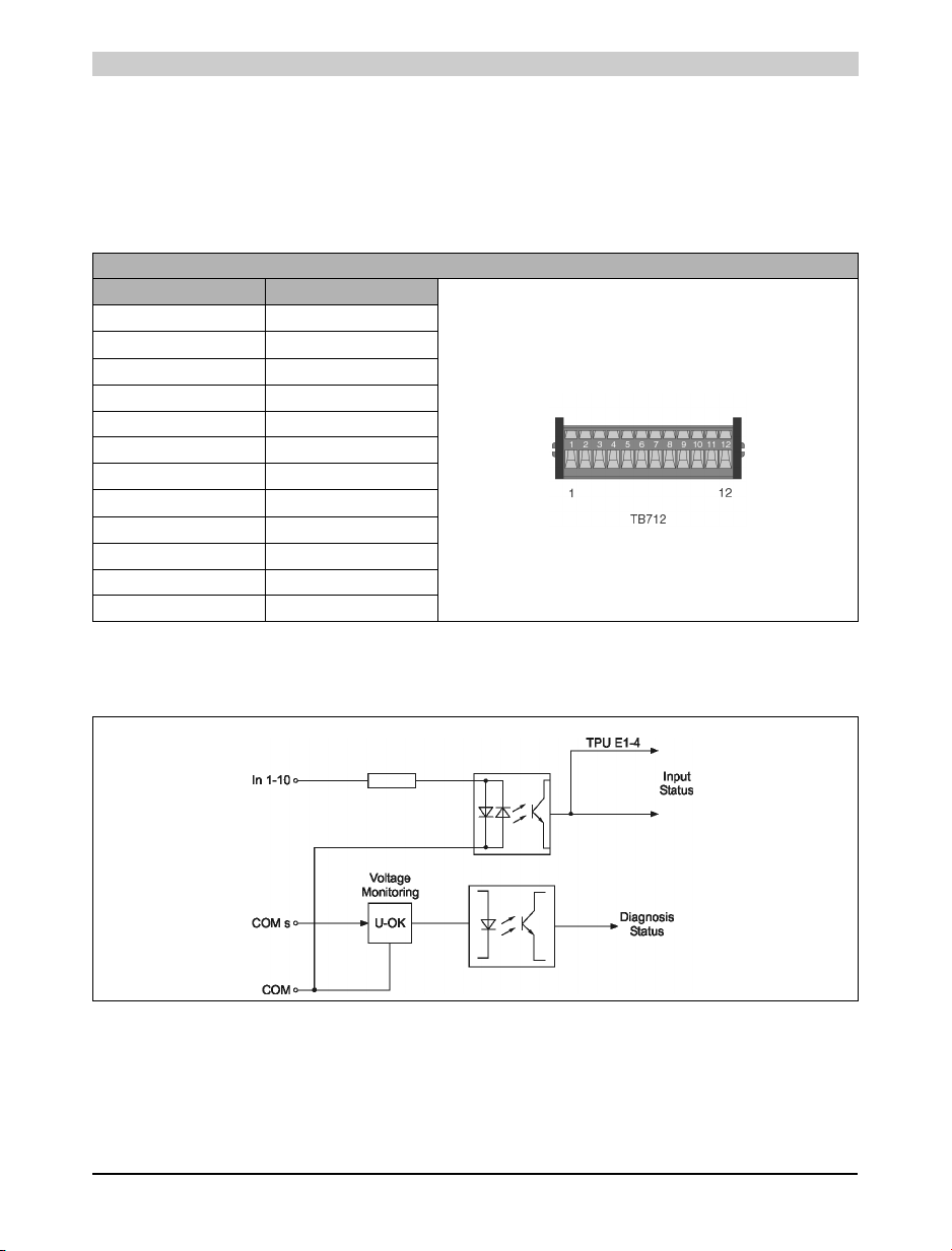
Inputs 1 - 4 are equipped with additional functions (event counter, ABR evaluation, etc.). The
supply voltage for the digital inputs can be monitored with the application program.
Digital inputs pin assignments
Connection Description
1 Input 1
2 Input 2
3 Input 3
4 Input 4
5 Input 5
6 Input 6
7 Input 7
8 Input 8
9 Input 9
10 Input 10
11 +24 VDC
12 GND
Table 21: Digital inputs pin assignments
X2
12.10.2 Input Circuit Diagram
Figure 18: Digital inputs - input circuit diagram
40 Power Panel User's Manual
Page 41
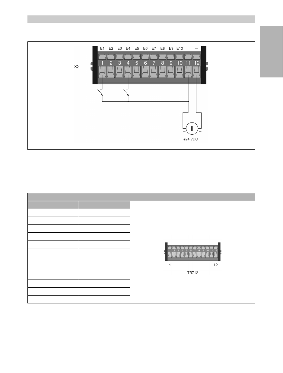
12.10.3 Connection Example
Figure 19: Digital inputs connection example
12.11 Digital Outputs
12.11.1 Terminal Block Connections
Power Panel • Description of Components
Chapter 1
Power Panel
Digital Outputs Pin Assignment
Connection Description
1 Output 1
2 Output 2
3 Output 3
4 Output 4
5 Output 5
6 Output 6
7 Output 7
8 Output 8
9 Potential-Free Relay Contact
10 Potential-Free Relay Contact
11 +24 VDC, outputs 1 - 8
12 GND, outputs 1 - 8
X3
Table 22: Digital outputs pin assignment
Power Panel User's Manual 41
Page 42
Power Panel • Description of Components
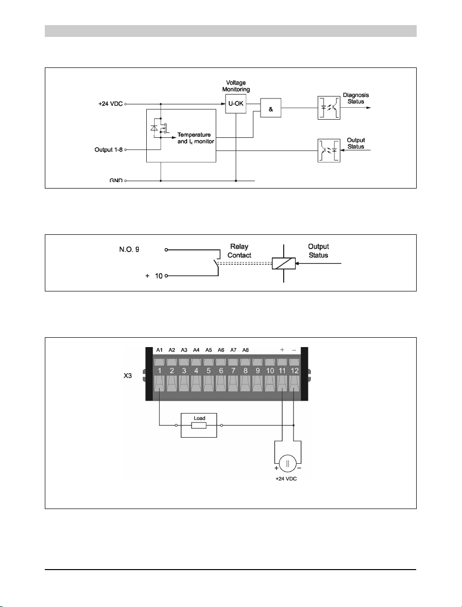
12.11.2 Output Circuit Diagram
Figure 20: Digital outputs - output circuit diagram
12.11.3 Output Circuit Diagram for Potential-Free Relay Contact
Figure 21: Connection example for relay contact
12.11.4 Connection Example for Outputs 1 - 8
Figure 22: Connection example for outputs 1 - 8
42 Power Panel User's Manual
Page 43
Power Panel • Description of Components
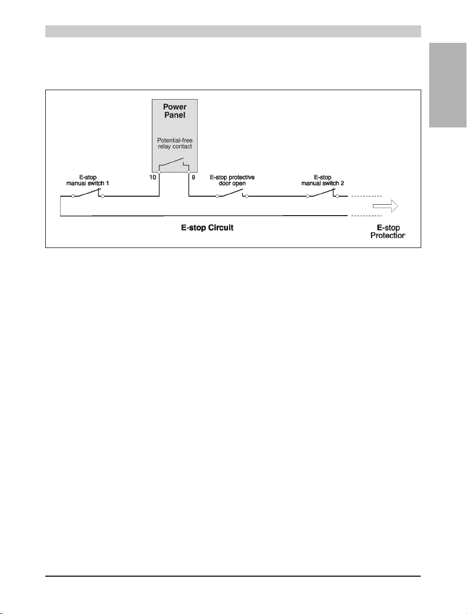
12.11.5 Connection Example for Potential-Free Relay Contact
Example 1: E-STOP Circuit
Figure 23: E-STOP circuit
Chapter 1
Power Panel
Power Panel User's Manual 43
Page 44
Power Panel • Changing the Battery
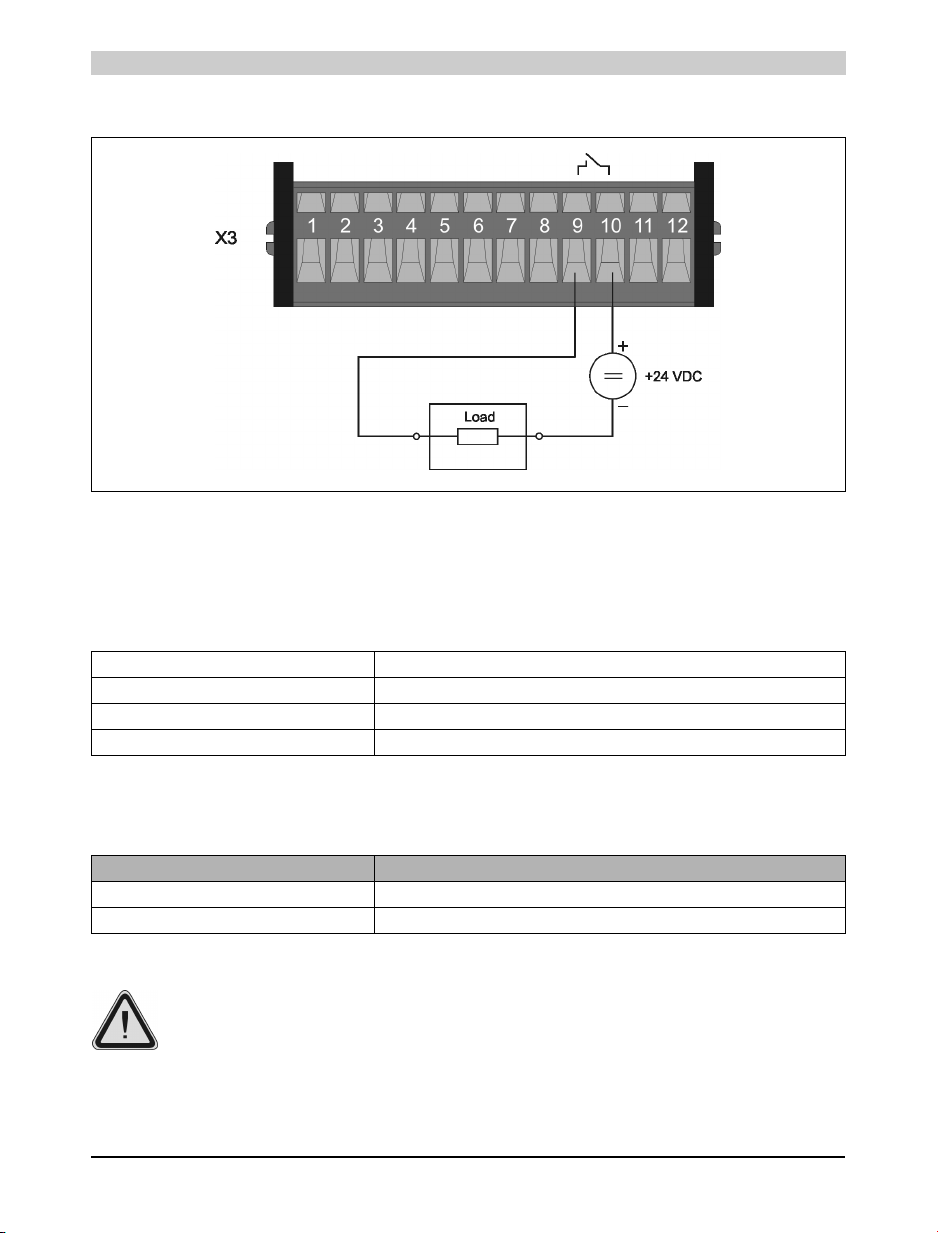
Example 2: Switching a Load
13. Changing the Battery
13.1 Battery Data
Figure 24: Switching a load
Lithium Battery 3 V / 950 mAh
Model Number 0AC201.9 (5 lithium batteries)
Storage Time Max. 3 years at 30 °C
Relative Humidity 0 to 95 % (non-condensing)
Table 23: Battery data
13.2 Buffer Duration
Buffer Curr ent Panel CPU
Typical 10 µA
Maximum 200 µA
Table 24: Buffer duration
B&R recommend changing the batteries after five years of operation.
44 Power Panel User's Manual
Page 45
Power Panel • Changing the Battery
Procedure
The product design allows the battery to be changed with the Power Panel switched on or off. In
some countries, safety regulations do not allow batteries to be changed while the module is
switched on.
The data in RAM is buffered up to 10 min due to the gold foil capacitors. During
this time period, a battery change without data loss is guaranteed.
• Touch the mounting rail or ground connection (not the power supply!) in order to discharge
any electrostatic charge from your body.
• Remove the cover from the lithium battery holder using a screwdriver.
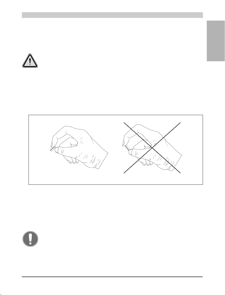
• Remove the battery from the holder by pulling the removal strip (don't use uninsulated tools
>- risk of short circuiting). The battery should not be held by its edges. Insulated tweezers
may also be used for removing the battery.
Chapter 1
Power Panel
Correct Incorrect
Figure 25: Handling the battery
• Insert the new battery with correct polarity. The removal strip should be protruding from the
battery holder and the "+" side of the battery should be facing downward. In order to be
able to remove the battery again in future, the removal strip must protrude from the upper
side of the battery.
• Now wrap the end of the removal strip over the top of the battery and insert it underneath
the battery so that it does not protrude from the battery holder.
Lithium batteries are considered hazardous waste! Used batteries should be
disposed of accordingly.
Power Panel User's Manual 45
Page 46

Power Panel • Changing the Battery
46 Power Panel User's Manual
Page 47

Technical Appendix • Décor Foil (polyester foil)
Chapter 2 • Technical Appendix
1. Décor Foil (polyester foil)
The décor foil used by B&R conforms to DIN 42 115 (section 2). This means it is resistant to
exposure to the following chemicals for a 24 hour period with no visible signs of damage:
Ethanol
Cyclohexanol
Diacetone alcohol
Glycol Isopropanol
Glycerin
Methanol
Triacetin
Dowandol DRM/PM
Acetone
Methyl ethyl ketone
Dioxan
Cyclohexanone
MIBK
Isophorone
Ammonia <40%
Caustic soda <40%
Potassium hydroxide
Alkali carbonate
Bichromate
Potassium
Ferro cyanide/ Ferro cyanide
Acetonitrile
Sodium bisulphate
Formaldehyde 37% - 42%
Acetaldehyde
Aliphatic hydrocarbons
Toluene
Xylene
White spirits
Formic acid <50%
Acetic acid <50%
Phosphoric acid <30%
Hydrochloric acid <36%
Nitric acid <10%
Trichloracetic acid <50%
Sulphuric acid <10%
Cutting oil
Diesel oil
Linseed oil
Paraffin oil
Blown castor oil
Silicon oil
Turpentine oil substitute
Universal brake fluid
Decon
Aviation fuel
Petrol
Water
Sea water
Table 25: Resistance to chemicals
Trichloroethane
Ethyl acetate
Diethyl ether
N-Butyl acetate
Amyl acetate
Butylcellosolve
Ether
Sodium hypochlorite <20%
Hydrogen peroxide <25%
Potassium carbonate
Washing powders
Fabric conditioner
Ferric chloride
Ferrous chloride (FeCl2)
Ferrous chloride (FeCl3)
Dibutyl Phthalate
Dioctyl Phthalate
Sodium carbonate
Chapter 2
Technical Appendix
The décor foil conforms to DIN 42 115 section 2 for exposure to glacial acetic acid < 1 hour
without any sign of visible damage.
Power Panel User's Manual 47
Page 48
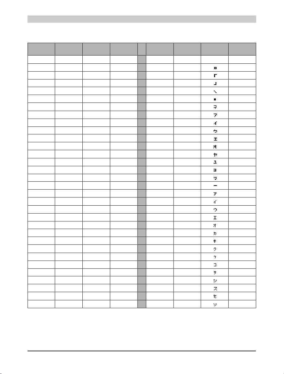
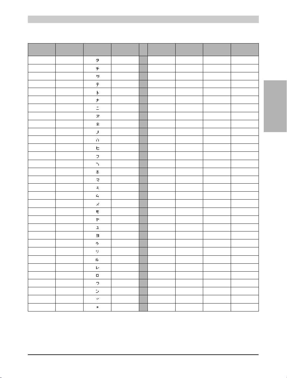
Technical Appendix • Characters for LC Displays (English/Katakana)
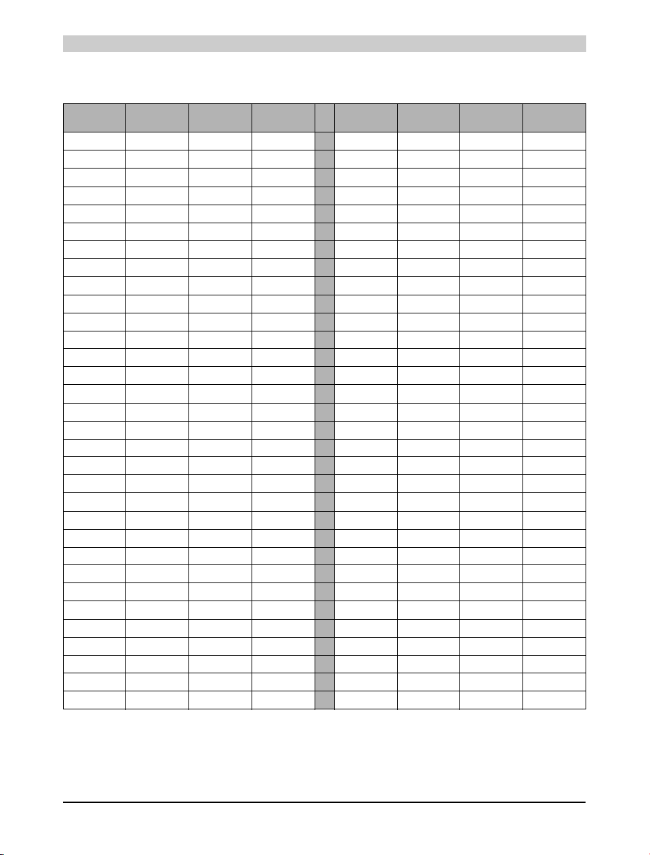
2. Characters for LC Displays (English/Katakana)
Dec. Hex. Character Controller
000 $00 032 $20 SPC
001 $01
002 $02
003 $03
004 $04
005 $05
006 $06
007 $07
008 $08 BS
009 $09
010 $0A LF
011 $0B
012 $0C
013 $0D
014 $0E
015 $0F
016 $10
017 $11 XON
018 $12 DC2
019 $13 XOFF
020 $14 DC4
021 $15
022 $16 SYN
023 $17
024 $18
025 $19
026 $1A
027 $1B ESC
028 $1C
029 $1D
030 $1E
031 $1F
Character
Dec. Hex. Character Controller
033 $21 !
034 $22 "
035 $23 #
036 $24 $
037 $25 %
038 $26 &
039 $27 ’
040 $28 (
041 $29 )
042 $2A *
043 $2B +
044 $2C ,
045 $2D -
046 $2E .
047 $2F /
048 $30 0
049 $31 1
050 $32 2
051 $33 3
052 $34 4
053 $35 5
054 $36 6
055 $37 7
056 $38 8
057 $39 9
058 $3A :
059 $3B ;
060 $3C <
061 $3D =
062 $3E >
063 $3F ?
Character
48 Power Panel User's Manual
Page 49
Technical Appendix • Characters for LC Displays (English/Katakana)
Dec. Hex. Character
064 $40 @
065 $41 A
066 $42 B
067 $43 C
068 $44 D
069 $45 E
070 $46 F
071 $47 G
072 $48 H
073 $49 I
074 $4A J
075 $4B K
076 $4C L
077 $4D M
078 $4E N
079 $4F O
080 $50 P
081 $51 Q
082 $52 R
083 $53 S
084 $54 T
085 $55 U
086 $56 V
087 $57 W
088 $58 X
089 $59 Y
090 $5A Z
091 $5B [
092 $5C ¥
093 $5D ]
094 $5E ^
095 $5F _
Controller
Character
Dec. Hex. Character
096 $60 ‘
097 $61 a
098 $62 b
099 $63 c
100 $64 d
101 $65 e
102 $66 f
103 $67 g
104 $68 h
105 $69 i
106 $6A j
107 $6B k
108 $6C l
109 $6D m
110 $6E n
111 $6F o
112 $70 p
113 $71 q
114 $72 r
115 $73 s
116 $74 t
117 $75 u
118 $76 v
119 $77 w
120 $78 x
121 $79 y
122 $7A z
123 $7B {
124 $7C |
125 $7D }
126 $7E ?
127 $7F ?
Controller
Character
Chapter 2
Technical Appendix
Power Panel User's Manual 49
Page 50
Technical Appendix • Characters for LC Displays (English/Katakana)
Dec. Hex. Character Controller
128 $80 Free
129 $81 e
130 $82 Free
131 $83 Free
132 $84 u
133 $85 Free
134 $86 Free
135 $87 Free
136 $88 Free
137 $89 Free
138 $8A Free
139 $8B Free
140 $8C Free
141 $8D Free
142 $8E Ä
143 $8F Free
144 $90 Free
145 $91 Free
146 $92 Free
147 $93 Free
148 $94 ö
149 $95 Free
150 $96 Free
151 $97 Free
152 $98 Free
153 $99 Ö
154 $9A Ü
155 $9B Free
156 $9C Free
157 $9D Free
158 $9E Free
159 $9F Free
Character
Dec. Hex. Character Controller
160 $A0 Free
161 $A1
162 $A2
163 $A3
164 $A4
165 $A5
166 $A6
167 $A7
168 $A8
169 $A9
170 $AA
171 $AB
172 $AC
173 $AD
174 $AE
175 $AF
176 $B0
177 $B1
178 $B2
179 $B3
180 $B4
181 $B5
182 $B6
183 $B7
184 $B8
185 $B9
186 $BA
187 $BB
188 $BC
189 $BD
190 $BE
191 $BF
Character
50 Power Panel User's Manual
Page 51
Technical Appendix • Characters for LC Displays (English/Katakana)
Dec. Hex. Character Controller
192 $C0
193 $C1
194 $C2
195 $C3
196 $C4
197 $C5
198 $C6
199 $C7
200 $C8
201 $C9
202 $CA
203 $CB
204 $CC
205 $CD
206 $CE
207 $CF
208 $D0
209 $D1
210 $D2
211 $D3
212 $D4
213 $D5
214 $D6
215 $D7
216 $D8
217 $D9
218 $DA
219 $DB
220 $DC
221 $DD
222 $DE
223 $DF
Character
Dec. Hex. Character Controller
224 $E0 Free
225 $E1 ß
226 $E2 Free
227 $E3 Free
228 $E4 Free
229 $E5 Free
230 $E6 Free
231 $E7 Free
232 $E8 Free
233 $E9 Free
234 $EA Free
235 $EB Free
236 $EC Free
237 $ED Free
238 $EE Free
239 $EF Free
240 $F0 Free
241 $F1 Free
242 $F2 Free
243 $F3 Free
244 $F4 Free
245 $F5 Free
246 $F6 Free
247 $F7 Free
248 $F8 Free
249 $F9 Free
250 $FA Free
251 $FB Free
252 $FC Free
253 $FD Free
254 $FE Free
255 $FF Free
Character
Chapter 2
Technical Appendix
Power Panel User's Manual 51
Page 52

Technical Appendix • Characters for LC Displays (English/Katakana)
52 Power Panel User's Manual
Page 53

Index
B
Battery ...................................................... 44
buffer duration ........................................... 44
C
CAN Interface ........................................... 35
Character Set ............................................ 48
D
Décor ........................................................ 47
Décor foil ................................................... 47
Device Label ............................................. 33
Digital Inputs ............................................. 40
Digital Outputs .......................................... 41
E
EX101
Dimensions ............................................ 28
General Information ............................... 25
Images ................................................... 27
Installation ............................................. 29
Order Data ............................................. 25
Photo ..................................................... 26
Technical Data ...................................... 27
I
M
Manual History ............................................ 9
Mounting Instructions ............................... 32
O
Operating Mode Switch ............................ 36
P
PCMCIA Interface ..................................... 37
Power Panel Expansion ........................... 25
Power Panel Interface .............................. 38
Power Panel PP21 ................................... 12
Dimensions ........................................... 18
Images .................................................. 17
Order Data ............................................ 12
Photo ..................................................... 13
Technical Data ...................................... 13
Power Panel PP41 ................................... 19
Dimensions ........................................... 25
Images .................................................. 24
Order Data ............................................ 19
Photo ..................................................... 20
Technical Data ...................................... 20
Power Supply ........................................... 34
Programming ............................................ 33
Programming System Flash ..................... 37
Programming the PLC CPU ..................... 33
Index
IF370 ......................................................... 30
General Information ............................... 30
Order Data ............................................. 30
Photo ..................................................... 30
Pin Assignments .................................... 31
Status LEDs .......................................... 31
Technical Data ...................................... 30
IF370 CAN Interface Module .................... 30
Interfaces .................................................. 35
K
Katakana ................................................... 48
Power Panel User's Manual 53
R
Realtime Buffering .................................... 39
RS232 Interface ........................................ 36
S
Safety Guidelines ....................................... 7
Design ..................................................... 9
Installation ............................................... 8
Intended Use ........................................... 7
Introduction ............................................. 7
Operation ................................................ 8
Screw-in Modules ..................................... 38
Status LEDs .............................................. 34
Page 54

Index
T
Technical Appendix .................................. 47
Terminal Block .......................................... 40
V
Visualization ............................................. 33
54 Power Panel User's Manual
Page 55

Index
Index
Power Panel User's Manual 55
Page 56

Index
56 Power Panel User's Manual
 Loading...