

B&R Panel PC 800, MAPPC800-ENG User Manual

Panel PC 800
User's Manual
Version: 1.00 (Mai 2010)
Model number: MAPPC800-ENG
All information contained in this manual is current as of its creation/publication. We reserve the
right to change the contents of this manual without warning. The information contained herein is
believed to be accurate as of the date of publication; however, Bernecker + Rainer IndustrieElektronik Ges.m.b.H. makes no warranty, expressed or implied, with regards to the products or
the documentation contained within this book. In addition, Bernecker + Rainer IndustrieElektronik Ges.m.b.H. shall not be liable in the event of incidental or consequential damages in
connection with or resulting from the furnishing, performance, or use of these products. The
software names, hardware names, and trademarks used in this manual are registered by the
respective companies.
1Panel PC 800 User's Manual V 1.00

2 Panel PC 800 User's Manual V 1.00 3Panel PC 800 User's Manual V 1.00

Chapter 1: General information
Chapter 2: Technical data
Chapter 3: Commissioning
Chapter 4: Software
Chapter 5: Standards and certifications
Chapter 6: Accessories

4 Panel PC 800 User's Manual V 1.00 5Panel PC 800 User's Manual V 1.00

Chapter 7: Maintenance / Servicing
Appendix A
Figure index
Table index
Model number index
Index

6 Panel PC 800 User's Manual V 1.00

Table of contents
Chapter 1: General information ..................................................... 17
1. Manual history .................................................................................................................... 17
2. Safety notices ..................................................................................................................... 19
2.1 Intended use .................................................................................................................. 19
2.2 Protection against electrostatic discharges ................................................................... 19
2.2.1 Packaging ............................................................................................................... 19
2.2.2 Guidelines for proper ESD handling ....................................................................... 19
2.3 Policy and procedures ................................................................................................... 20
2.4 Transport and storage ................................................................................................... 20
2.5 Installation ..................................................................................................................... 21
2.6 Operation ....................................................................................................................... 21
2.6.1 Protection against touching electrical parts ............................................................ 21
2.6.2 Environmental conditions - dust, humidity, aggressive gases ................................ 21
2.6.3 Programs, viruses, and dangerous programs ......................................................... 22
2.7 Environmentally-friendly disposal .................................................................................. 22
2.7.1 Separation of materials ........................................................................................... 22
3. Organization of safety notices ............................................................................................ 23
4. Directives ............................................................................................................................ 23
5. Model numbers ................................................................................................................... 24
5.1 System units .................................................................................................................. 24
5.2 CPU boards 945GME COM Express ............................................................................ 24
5.3 Heat sink ....................................................................................................................... 25
5.4 Main memory ................................................................................................................. 25
5.5 Expansion ...................................................................................................................... 25
5.6 Bus units ........................................................................................................................ 25
5.7 Option ............................................................................................................................ 26
5.8 Plug-in cards ................................................................................................................. 26
5.9 Drives ............................................................................................................................ 26
5.10 Fan kits ........................................................................................................................ 27
5.11 Accessories ................................................................................................................. 27
5.11.1 Batteries ................................................................................................................ 27
5.11.2 Supply voltage connectors .................................................................................... 27
5.11.3 UPS module + accessories ................................................................................... 27
5.11.4 External UPS ........................................................................................................ 28
5.11.5 CompactFlash cards ............................................................................................. 28
5.11.6 USB flash drives ................................................................................................... 29
5.11.7 Cables ................................................................................................................... 29
5.11.8 Miscellaneous ....................................................................................................... 30
5.12 Software ...................................................................................................................... 31
Chapter 2: Technical data .............................................................. 33
1. Introduction ......................................................................................................................... 33
1.1 Features ........................................................................................................................ 34
1.2 System components / Configuration ............................................................................. 35
1.2.1 Configuration - Basic system .................................................................................. 35
1.2.2 Configuration - Optional components ..................................................................... 36
7Panel PC 800 User's Manual V 1.00

Table of contents
2. Entire device ....................................................................................................................... 37
2.1 Temperature specifications ........................................................................................... 37
2.1.1 Maximum ambient temperature .............................................................................. 38
2.1.2 Minimum ambient temperature ............................................................................... 39
2.1.3 How do you determine the maximum ambient temperature? ................................. 40
2.1.4 Temperature monitoring .......................................................................................... 40
2.2 Humidity specifications .................................................................................................. 41
2.3 Power management ...................................................................................................... 42
2.3.1 Block diagram - supply voltage ............................................................................... 42
2.3.2 Power calculation with 5PC820.1505-00 ................................................................ 43
2.3.3 Power calculation with 5PC820.1906-00 ................................................................ 44
2.4 Block diagram ................................................................................................................ 45
2.5 Serial number sticker ..................................................................................................... 46
2.6 Device interfaces ........................................................................................................... 48
2.6.1 +24 VDC supply voltage ......................................................................................... 48
2.6.2 Monitor / Panel connection - SDL (Smart Display Link / DVI) ................................. 50
2.6.3 Serial interface COM1 ............................................................................................. 51
2.6.4 Ethernet 1 (ETH1) ................................................................................................... 52
2.6.5 Ethernet 2 (ETH2) ................................................................................................... 53
2.6.6 USB interfaces (USB1, 2, 3, 4) ............................................................................... 54
2.6.7 MIC, Line IN, Line OUT ........................................................................................... 56
2.6.8 Add-on UPS slot ..................................................................................................... 57
2.6.9 Status LEDs ............................................................................................................ 58
2.6.10 CMOS profile switch ............................................................................................. 59
2.6.11 Power button ......................................................................................................... 60
2.6.12 Reset button .......................................................................................................... 60
2.6.13 Battery ................................................................................................................... 61
2.6.14 CompactFlash slot 1 ............................................................................................. 62
2.6.15 CompactFlash slot 2 ............................................................................................. 63
2.6.16 Slide-in compact slot ............................................................................................. 64
2.6.17 PCIec slot (card slot) ............................................................................................. 65
3. Individual components ........................................................................................................ 66
3.1 System units .................................................................................................................. 66
3.1.1 Panel PC 5PC820.1505-00 ..................................................................................... 66
3.1.2 Panel PC 5PC820.1906-00 ..................................................................................... 72
3.2 CPU boards 945GME .................................................................................................... 78
3.2.1 Technical data ......................................................................................................... 78
3.3 Heat sink ....................................................................................................................... 79
3.3.1 Technical data ......................................................................................................... 79
3.4 Main memory ................................................................................................................. 80
3.4.1 Technical data ......................................................................................................... 80
3.5 Expansion ...................................................................................................................... 81
3.5.1 Technical data ......................................................................................................... 82
3.5.2 Dimensions - 5PC803.SX01-00 .............................................................................. 82
3.5.3 Dimensions - 5PC803.SX02-00 .............................................................................. 83
3.5.4 Slot for bus units ..................................................................................................... 84
3.5.5 Slide-in slot 1 .......................................................................................................... 85
8 Panel PC 800 User's Manual V 1.00

Table of contents
3.6 Bus units ........................................................................................................................ 86
3.6.1 Technical data ......................................................................................................... 87
3.7 Option ............................................................................................................................ 88
3.8 Plug-in cards ................................................................................................................. 89
3.8.1 Ethernet Card 10/100/1000 - 5ACPCC.ETH0-00 ................................................... 90
3.8.2 POWERLINK card 2-port - 5ACPCC.MPL0-00 ....................................................... 92
3.9 Drives ............................................................................................................................ 95
3.9.1 Slide-in compact HDD 40GB EE25 - 5AC801.HDDI-00 ......................................... 95
3.9.2 Slide-in compact HDD 160 GB 24x7 ET - 5AC801.HDDI-02 .................................. 98
3.9.3 Slide-in compact SSD - 5AC801.SSDI-00 ............................................................ 101
3.9.4 Hard disk adapter (slide-in compact) - 5AC801.ADAS-00 .................................... 105
3.9.5 Slide-in HDD EE25 - 5AC801.HDDS-00 ............................................................... 106
3.9.6 Slide-in DVD-ROM - 5AC801.DVDS-00 ............................................................... 109
3.9.7 Slide-in DVD-R/RW - 5AC801.DVRS-00 .............................................................. 112
3.9.8 PCI SATA RAID 2 x 160 GB 24x7 ET - 5ACPCI.RAIC-03 .................................... 116
3.9.9 Replacement PCI SATA RAID HDD 160 GB - 5ACPCI.RAIC-04 ......................... 121
3.10 Fan kits ...................................................................................................................... 124
3.10.1 Fan kit 1 card slot - 5AC803.FA01-00 ................................................................. 124
3.10.2 Fan kit 2 card slot - 5AC803.FA02-00 ................................................................. 125
3.10.3 Fan kit 3 card slot - 5AC803.FA03-00 ................................................................. 126
Chapter 3: Commissioning .......................................................... 127
1. Installation ......................................................................................................................... 127
1.1 Important mounting information ................................................................................... 128
1.2 Mounting orientation .................................................................................................... 129
1.2.1 Standard mounting ................................................................................................ 129
1.2.2 Standard mounting with 5AC801.DVRS-00 .......................................................... 130
1.2.3 Standard mounting with 5AC801.DVDS-00 .......................................................... 131
1.2.4 Spacing for air circulation. ..................................................................................... 132
2. Cable connections ............................................................................................................ 133
3. Grounding concept ........................................................................................................... 134
4. Connection examples ....................................................................................................... 135
4.1 Selecting the display units ........................................................................................... 135
4.2 One Automation Panel 900 via DVI ............................................................................. 136
4.2.1 Basic system requirements ................................................................................... 136
4.2.2 Link modules ......................................................................................................... 137
4.2.3 Cables ................................................................................................................... 137
4.2.4 Possible Automation Panel units, resolutions und segment lengths ..................... 137
4.2.5 BIOS settings ........................................................................................................ 138
4.3 One Automation Panel 900 via SDL ............................................................................ 139
4.3.1 Basic system requirements ................................................................................... 139
4.3.2 Link modules ......................................................................................................... 140
4.3.3 Cables ................................................................................................................... 140
4.3.4 BIOS settings ........................................................................................................ 141
4.4 One Automation Panel 800 via SDL ............................................................................ 142
4.4.1 Basic system requirements ................................................................................... 142
9Panel PC 800 User's Manual V 1.00

Table of contents
4.4.2 Cables ................................................................................................................... 143
4.4.3 BIOS settings ........................................................................................................ 144
4.5 One AP900 and one AP800 via SDL .......................................................................... 145
4.5.1 Basic system requirements ................................................................................... 145
4.5.2 Link modules ......................................................................................................... 146
4.5.3 Cables ................................................................................................................... 146
4.5.4 BIOS settings ........................................................................................................ 146
4.6 Four Automation Panel 900 units via SDL .................................................................. 147
4.6.1 Basic system requirements ................................................................................... 147
4.6.2 Link modules ......................................................................................................... 148
4.6.3 Cables ................................................................................................................... 148
4.6.4 BIOS settings ........................................................................................................ 150
5. Touch screen calibration ................................................................................................... 151
5.1 Windows XP Professional ........................................................................................... 151
5.2 Windows CE ................................................................................................................ 151
5.3 Windows XP Embedded .............................................................................................. 151
5.4 Windows Embedded Standard 2009 ........................................................................... 151
5.5 Automation Runtime / Visual Components .................................................................. 151
6. Connection of USB peripheral devices ............................................................................. 152
6.1 Locally on the PPC800 ................................................................................................ 152
6.2 Remote connection to Automation Panel 900 via DVI ................................................ 153
6.3 Remote connection to Automation Panel 800/900 via SDL ........................................ 154
7. Configuration of a SATA RAID array ................................................................................ 155
7.1 Create RAID set .......................................................................................................... 156
7.1.1 Create RAID set - Striped ..................................................................................... 157
7.1.2 Create RAID set - Mirrored ................................................................................... 158
7.2 Delete RAID set ........................................................................................................... 159
7.3 Rebuild mirrored set .................................................................................................... 160
7.4 Resolve conflicts ......................................................................................................... 161
7.5 Low level format .......................................................................................................... 162
8. Known problems / issues .................................................................................................. 163
9. User tips for increasing the display lifespan ..................................................................... 164
9.1 Backlight ...................................................................................................................... 164
9.1.1 How can the lifespan of backlights be extended? ................................................. 164
9.2 Image sticking ............................................................................................................. 164
9.2.1 What causes image sticking? ............................................................................... 164
9.2.2 How can image sticking be avoided? .................................................................... 165
Chapter 4: Software ...................................................................... 167
1. BIOS options ..................................................................................................................... 167
1.1 General information ..................................................................................................... 167
1.2 BIOS setup and boot procedure .................................................................................. 167
1.2.1 BIOS setup keys ................................................................................................... 168
1.3 Main ............................................................................................................................. 170
1.4 Advanced .................................................................................................................... 171
1.4.1 ACPI configuration ................................................................................................ 173
10 Panel PC 800 User's Manual V 1.00

Table of contents
1.4.2 PCI Configuration .................................................................................................. 175
1.4.3 PCI express configuration ..................................................................................... 179
1.4.4 Graphics configuration .......................................................................................... 181
1.4.5 CPU configuration ................................................................................................. 185
1.4.6 Chipset configuration ............................................................................................ 186
1.4.7 I/O interface configuration ..................................................................................... 188
1.4.8 Clock Configuration ............................................................................................... 189
1.4.9 IDE Configuration .................................................................................................. 190
1.4.10 USB configuration ............................................................................................... 198
1.4.11 Keyboard/mouse configuration ........................................................................... 200
1.4.12 Remote access configuration .............................................................................. 201
1.4.13 CPU board monitor ............................................................................................. 203
1.4.14 Main Board/Panel Features ................................................................................ 204
1.5 Boot ............................................................................................................................. 210
1.6 Security ....................................................................................................................... 212
1.6.1 Hard disk security user password ......................................................................... 213
1.6.2 Hard disk security master password ..................................................................... 214
1.7 Power .......................................................................................................................... 215
1.8 Exit .............................................................................................................................. 217
1.9 BIOS default settings ................................................................................................... 217
1.9.1 Main ...................................................................................................................... 219
1.9.2 Advanced .............................................................................................................. 219
1.9.3 Boot ....................................................................................................................... 226
1.9.4 Security ................................................................................................................. 227
1.9.5 Power .................................................................................................................... 227
1.10 BIOS Error signals (beep codes) ............................................................................... 228
1.10.1 BIOS 945GME .................................................................................................... 228
1.11 Distribution of resources ............................................................................................ 229
1.11.1 RAM address assignment ................................................................................... 229
1.11.2 I/O address assignment ...................................................................................... 230
1.11.3 Interrupt assignments in PCI mode ..................................................................... 231
1.11.4 Interrupt assignments in APCI mode .................................................................. 232
2. Upgrade information ......................................................................................................... 234
2.1 BIOS upgrade .............................................................................................................. 234
2.1.1 What information do I need? ................................................................................. 234
2.1.2 BIOS upgrade for 945GME COM Express ........................................................... 237
2.2 Firmware upgrade ....................................................................................................... 238
2.2.1 Procedure ............................................................................................................. 238
2.2.2 Possible upgrade problems and software dependencies (for V1.02) ................... 240
2.3 Creating an MS-DOS boot diskette in Windows XP .................................................... 241
2.4 Creating a bootable USB flash drive for B&R upgrade files ........................................ 243
2.4.1 Requirements ........................................................................................................ 243
2.4.2 Procedure ............................................................................................................. 243
2.4.3 Where do I get MS-DOS? ..................................................................................... 244
2.5 Creating a bootable CompactFlash card for B&R upgrade files .................................. 245
2.5.1 Requirements ........................................................................................................ 245
2.5.2 Procedure ............................................................................................................. 245
11Panel PC 800 User's Manual V 1.00

Table of contents
2.5.3 Where do I get MS-DOS? ..................................................................................... 246
2.6 Upgrade problems ....................................................................................................... 246
3. Panel PC 800 with MS-DOS ............................................................................................. 247
3.1 Known problems .......................................................................................................... 247
4. Panel PC 800 with Windows XP Professional .................................................................. 249
4.1 Installation ................................................................................................................... 249
5. Panel PC 800 with Windows XP Embedded .................................................................... 250
5.1 General information ..................................................................................................... 250
5.2 Features with FP2007 (Feature Pack 2007) ............................................................... 251
5.3 Installation ................................................................................................................... 252
5.4 Drivers ......................................................................................................................... 252
5.4.1 Touch screen driver .............................................................................................. 252
6. Panel PC 800 with Windows Embedded Standard 2009 .................................................. 253
6.1 General information ..................................................................................................... 253
6.2 Features with WES2009 (Windows Embedded Standard 2009) ................................. 254
6.3 Installation ................................................................................................................... 255
6.4 Drivers ......................................................................................................................... 255
6.4.1 Touch screen driver .............................................................................................. 255
7. Panel PC 800 with Automation Runtime ........................................................................... 256
7.1 General information ..................................................................................................... 256
7.2 AR010 ......................................................................................................................... 256
8. Automation Device Interface (ADI) - Control Center ......................................................... 257
8.1 Function ....................................................................................................................... 257
8.2 Installation ................................................................................................................... 259
8.3 SDL equalizer setting .................................................................................................. 260
8.4 UPS configuration ....................................................................................................... 261
8.4.1 Installing the UPS service for the B&R APC add-on UPS .................................... 262
8.4.2 Displaying UPS status values ............................................................................... 262
8.4.3 Changing UPS battery settings ............................................................................. 264
8.4.4 Updating UPS battery settings .............................................................................. 265
8.4.5 Saving UPS battery settings ................................................................................. 266
8.4.6 Configuring UPS system settings ......................................................................... 266
8.4.7 Changing additional UPS settings ........................................................................ 268
Chapter 5: Standards and certifications ..................................... 271
1. Applicable European guidelines ....................................................................................... 271
2. Overview of standards ...................................................................................................... 271
3. Emission requirements (emission) .................................................................................... 273
3.1 Network-related emissions .......................................................................................... 274
3.2 Emissions, electromagnetic emissions ........................................................................ 275
4. Requirements for immunity to disturbances (immunity) .................................................... 276
4.1 Electrostatic discharge (ESD) ..................................................................................... 277
4.2 High-frequency electromagnetic fields (HF field) ........................................................ 277
4.3 High-speed transient electrical disturbances (burst) ................................................... 278
4.4 Surges (surge) ............................................................................................................. 278
4.5 Conducted disturbances .............................................................................................. 279
12 Panel PC 800 User's Manual V 1.00

Table of contents
4.6 Magnetic fields with electrical frequencies .................................................................. 279
4.7 Voltage dips, fluctuations and short-term interruptions ............................................... 279
4.8 Damped oscillatory waves ........................................................................................... 280
5. Mechanical conditions ...................................................................................................... 281
5.1 Vibration operation ...................................................................................................... 281
5.2 Vibration during transport (packaged) ......................................................................... 282
5.3 Shock during operation ............................................................................................... 282
5.4 Shock during transport (packaged) ............................................................................. 282
5.5 Toppling ....................................................................................................................... 282
5.6 Free fall (packaged) .................................................................................................... 283
6. Climate conditions ............................................................................................................ 284
6.1 Worst case operation .................................................................................................. 284
6.2 Dry heat ....................................................................................................................... 284
6.3 Dry cold ....................................................................................................................... 284
6.4 Large temperature fluctuations .................................................................................... 285
6.5 Temperature fluctuations in operation ......................................................................... 285
6.6 Humid heat, cyclic ....................................................................................................... 285
6.7 Humid heat, constant (storage) ................................................................................... 285
7. Safety ................................................................................................................................ 286
7.1 Ground resistance ....................................................................................................... 286
7.2 Insulation resistance .................................................................................................... 287
7.3 High voltage ................................................................................................................ 287
7.4 Residual voltage .......................................................................................................... 287
7.5 Leakage current .......................................................................................................... 288
7.6 Overload ...................................................................................................................... 288
7.7 Defective component ................................................................................................... 288
7.8 Voltage range .............................................................................................................. 288
8. Other tests ........................................................................................................................ 289
8.1 Protection type ............................................................................................................ 289
9. International certifications ................................................................................................. 290
Chapter 6: Accessories ................................................................ 291
1. Overview ........................................................................................................................... 291
2. Replacement CMOS batteries .......................................................................................... 294
2.1 Order data ................................................................................................................... 294
2.2 Technical data ............................................................................................................. 294
3. Supply voltage connector (TB103 3-pin) .......................................................................... 296
3.1 General information ..................................................................................................... 296
3.2 Order data ................................................................................................................... 296
3.3 Technical data ............................................................................................................. 296
4. DVI - monitor adapter 5AC900.1000-00 ........................................................................... 298
4.1 Order data ................................................................................................................... 298
5. USB interface cover (attached) ......................................................................................... 299
5.1 Order data ................................................................................................................... 299
6. Uninterruptible power supply ............................................................................................ 300
6.1 Features ...................................................................................................................... 301
13Panel PC 800 User's Manual V 1.00

Table of contents
6.2 Requirements .............................................................................................................. 301
6.3 Individual components ................................................................................................. 302
6.3.1 Add-on UPS module 5AC600.UPSI-00 ................................................................. 302
6.3.2 Battery unit 5AC600.UPSB-00 .............................................................................. 304
6.3.3 UPS connection cable ........................................................................................... 308
7. External UPS .................................................................................................................... 309
7.1 General information ..................................................................................................... 309
7.2 Order data ................................................................................................................... 310
8. CompactFlash cards 5CFCRD.xxxx-04 ............................................................................ 311
8.1 General information ..................................................................................................... 311
8.2 Order data ................................................................................................................... 311
8.3 Technical data ............................................................................................................. 312
8.3.1 Temperature humidity diagram - Operation and storage ...................................... 314
8.4 Dimensions .................................................................................................................. 314
8.5 Benchmark .................................................................................................................. 315
9. CompactFlash cards - 5CFCRD.xxxx-03 .......................................................................... 316
9.1 General information ..................................................................................................... 316
9.2 Order data ................................................................................................................... 316
9.3 Technical data ............................................................................................................. 317
9.3.1 Temperature humidity diagram - Operation and storage ...................................... 319
9.4 Dimensions .................................................................................................................. 319
10. USB flash drive ............................................................................................................... 320
10.1 General information ................................................................................................... 320
10.2 Order data ................................................................................................................. 320
10.3 Technical data ........................................................................................................... 320
10.3.1 Temperature humidity diagram - Operation and storage .................................... 322
11. B&R Automation Studio 3.0USBdongle .......................................................................... 323
11.1 Order data ................................................................................................................. 323
12. HMI Drivers & Utilities DVD 5SWHMI.0000-00 ............................................................... 324
13. Cables ............................................................................................................................. 327
13.1 DVI cable 5CADVI.0xxx-00 ....................................................................................... 327
13.1.1 Order data ........................................................................................................... 327
13.1.2 Technical data ..................................................................................................... 328
13.1.3 Flex radius specification ...................................................................................... 328
13.1.4 Cable specifications ............................................................................................ 329
13.2 SDL cable 5CASDL.0xxx-00 ..................................................................................... 330
13.2.1 Order data ........................................................................................................... 330
13.2.2 Technical data ..................................................................................................... 331
13.2.3 Flex radius specification ...................................................................................... 331
13.2.4 Cable specifications ............................................................................................ 332
13.3 SDL cable with 45° plug 5CASDL.0xxx-01 ................................................................ 333
13.3.1 Order data ........................................................................................................... 333
13.3.2 Technical data ..................................................................................................... 334
13.3.3 Flex radius specification ...................................................................................... 334
13.3.4 Cable specifications ............................................................................................ 335
13.4 SDL flex cable 5CASDL.0xxx-03 ............................................................................... 336
13.4.1 Order data ........................................................................................................... 336
14 Panel PC 800 User's Manual V 1.00

Table of contents
13.4.2 Technical data ..................................................................................................... 337
13.4.3 Flex radius specification ...................................................................................... 338
13.4.4 Dimensions ......................................................................................................... 338
13.4.5 Structure ............................................................................................................. 339
13.4.6 Cable specifications ............................................................................................ 340
13.5 SDL flex cable with extender 5CASDL.0x00-13 ........................................................ 341
13.5.1 Order data ........................................................................................................... 341
13.5.2 Technical data ..................................................................................................... 341
13.5.3 Flex radius specification ...................................................................................... 343
13.5.4 Dimensions ......................................................................................................... 343
13.5.5 Cable connection ................................................................................................ 344
13.5.6 Cable specifications ............................................................................................ 345
13.6 RS232 cable .............................................................................................................. 346
13.6.1 Order data ........................................................................................................... 346
13.6.2 Technical data ..................................................................................................... 346
13.6.3 Cable specifications ............................................................................................ 347
13.7 USB cable ................................................................................................................. 348
13.7.1 Order data ........................................................................................................... 348
13.7.2 Technical data ..................................................................................................... 348
13.7.3 Cable specifications ............................................................................................ 349
Chapter 7: Maintenance / Servicing ............................................ 351
1. Changing the battery ........................................................................................................ 351
1.1 Battery test .................................................................................................................. 351
1.2 Procedure .................................................................................................................... 352
Appendix A .................................................................................... 353
1. Temperature sensor locations .......................................................................................... 353
2. Maintenance Controller Extended (MTCX) ....................................................................... 354
2.1 Temperature monitoring - Fan control ......................................................................... 355
3. B&R Key Editor ................................................................................................................. 356
4. B&R Automation Device Interface (ADI) development kit ................................................. 358
4.1 Installation ................................................................................................................... 359
5. Membrane ......................................................................................................................... 360
6. Viewing angles .................................................................................................................. 361
7. Glossary ............................................................................................................................ 362
15Panel PC 800 User's Manual V 1.00

Table of contents
16 Panel PC 800 User's Manual V 1.00

General information • Manual history
Chapter 1 • General information
Information:
B&R does its best to keep the printed versions of its user's manuals as current as
possible. However, any newer versions of the User's Manual can always be
downloaded in electronic form (pdf) from the B&R homepage www.br-
automation.com.
1. Manual history
Version Date Change
0.10 Preliminary 2009-11-10 - First version
Table 1: Manual history
Section 1
General information
17Panel PC 800 User's Manual V 1.00

General information • Manual history
Version Date Change
1.00 2010-05-06 - Dimension diagrams for the PPC800 system units corrected.
- Section 1 "Temperature sensor locations", on page 353 expanded.
- Additional point added to section 8 "Known problems / issues", on page 163.
- Section 2.2 "Firmware upgrade", on page 238 updated.
- Section 2.1 "Temperature specifications", on page 37 updated.
- Section 2.2 "Humidity specifications", on page 41 updated.
- Section 2.3 "Power management", on page 42 updated.
- Section 2.4 "Block diagram", on page 45 updated.
- Section 7 "Panel PC 800 with Automation Runtime", on page 256 updated.
- Section 2.5 "Serial number sticker", on page 46 updated.
- Section 3.10 "Fan kits", on page 124 updated.
- Section 2.1 "Temperature monitoring - Fan control", on page 355 updated.
- Section 8 "Automation Device Interface (ADI) - Control Center", on page 257 updated.
- Section 5 "Touch screen calibration", on page 151 updated.
- Section 6 "Connection of USB peripheral devices", on page 152 updated.
- Section 1.2.4 "Spacing for air circulation.", on page 132 updated.
- Section 1.2 "Mounting orientation", on page 129 updated.
- Section 6 "Panel PC 800 with Windows Embedded Standard 2009", on page 253 updated.
- Section 4 "Connection examples", on page 135 updated.
- Chapter 5 "Standards and certifications", on page 271 updated.
- The dongle 1A4300.LZ1U was updated, see section 11 "B&R Automation Studio 3.0USBdongle", on
page 323.
- Technical data updated for the system units 5PC820.1505-00 and 5PC820.1906-00.
- Technical data revised for the sections 13.2 "SDL cable 5CASDL.0xxx-00", 13.3 "SDL cable with 45°
plug 5CASDL.0xxx-01", 13.4 "SDL flex cable 5CASDL.0xxx-03" and 13.5 "SDL flex cable with
extender 5CASDL.0x00-13".
- Warning regarding replacement of batteries updated in section 2 "Replacement CMOS batteries", on
page 294 and 1 "Changing the battery", on page 351.
- Figures updated for expansions, options and bus units.
- CPU boards 5PC800.B945-05, 5PC800.B945-10, 5PC800.B945-11, 5PC800.B945-12,
5PC800.B945-13 and 5PC800.B945-14 were updated.
- Description of +24 VDC supply voltage changed on page 48.
- USB port caps (attached) 5AC900.1200-01, 5AC900.1200-02 and 5AC900.1200-03 updated in
Chapter 6 "Accessories".
- The PCI SATA RAID controller 5ACPCI.RAIC-03 and the replacement PCI SATA RAID HDD
5ACPCI.RAIC-04 were updated.
- Section 7 "Configuration of a SATA RAID array", on page 155 updated.
Table 1: Manual history
18
Panel PC 800 User's Manual V 1.00

2. Safety notices
2.1 Intended use
General information • Safety notices
Programmable logic controllers (PLCs), operating and monitoring devices (industrial PCs, Power
Panels, Mobile Panels, etc.), and B&R uninterruptible power supplies have been designed,
developed, and manufactured for conventional use in industry. They were not designed,
developed, and manufactured for any use involving serious risks or hazards that could lead to
death, injury, serious physical damage, or loss of any kind without the implementation of
exceptionally stringent safety precautions. In particular, such risks and hazards include the use
of these devices to monitor nuclear reactions in nuclear power plants, as well as flight control
systems, flight safety, the control of mass transit systems, medical life support systems and the
control of weapons systems.
2.2 Protection against electrostatic discharges
Electrical components that are vulnerable to electrostatic discharge (ESD) must be handled
accordingly.
2.2.1 Packaging
• Electrical components with housing
… do not require special ESD packaging, but must be handled properly
(see "Electrical components with housing").
• Electrical components without housing
… must be protected by ESD-suitable packaging.
2.2.2 Guidelines for proper ESD handling
Electrical components with housing
Section 1
General information
• Do not touch the connector contacts on connected cables.
• Do not touch the contact tips on the circuit boards.
Electrical components without housing
In addition to "Electrical components with housing", the following also applies:
• Any persons handling electrical components or devices that will be installed in the
electrical components must be grounded.
• Components can only be touched on the small sides or on the front plate.
• Components should always be stored in a suitable medium (ESD packaging, conductive
foam, etc.).
Metallic surfaces are not suitable storage surfaces!
19Panel PC 800 User's Manual V 1.00

General information • Safety notices
• Electrostatic discharges should be avoided on the components (e.g. through charged
plastics).
• A minimum distance of 10 cm must be kept from monitors and TV sets.
• Measurement devices and equipment must be grounded.
• Measurement probes on potential-free measurement devices must be discharged on
sufficiently grounded surfaces before taking measurements.
Individual components
• ESD protective measures for individual components are thoroughly integrated at B&R
(conductive floors, footwear, arm bands, etc.).
The increased ESD protective measures for individual components are not necessary for our
customers for handling B&R products.
2.3 Policy and procedures
Electronic devices are generally not failsafe. In the event of a failure on the programmable
control system operating or monitoring device, or uninterruptible power supply, the user is
responsible for ensuring that other devices that may be connected, e.g. motors, are in a secure
state.
Both when using programmable logic controllers and when using operating and monitoring
devices as control systems in conjunction with a soft PLC (e.g. B&R Automation Runtime or
comparable products) or a slot PLC (e.g. B&R LS251 or comparable products), the safety
precautions applying to industrial control systems (e.g. the provision of safety devices such as
emergency stop circuits, etc.) must be observed in accordance with applicable national and
international regulations. The same applies for all other devices connected to the system, such
as drives.
All tasks such as installation, commissioning, and maintenance are only permitted to be carried
out by qualified personnel. Qualified personnel are persons familiar with transport, ounting,
installation, commissioning, and operation of the product who also have the respective
qualifications (e.g. IEC 60364). National accident prevention guidelines must be followed.
The safety guidelines, connection descriptions (type plate and documentation), and limit values
listed in the technical data are to be read carefully before installation and commissioning and
must be observed.
2.4 Transport and storage
During transport and storage, devices must be protected from excessive stress (mechanical
load, temperature, humidity, aggressive atmospheres, etc.).
20
Panel PC 800 User's Manual V 1.00

General information • Safety notices
2.5 Installation
• Installation must take place according to the documentation, using suitable equipment
and tools.
• Devices must be installed without voltage applied and by qualified personnel.
• General safety regulations and nationally applicable accident prevention guidelines must
be observed.
• Electrical installation must be carried out according to the relevant guidelines (e.g. line
cross section, fuse, protective ground connection).
2.6 Operation
2.6.1 Protection against touching electrical parts
To operate programmable logic controllers, operating and monitoring devices or uninterruptible
power supplies, certain components must carry dangerous voltage levels of over 42 VDC. A lifethreatening electrical shock could occur if you come into contact with these parts. This could
result in death, severe injury or material damage.
Before turning on the programmable logic controller, the operating and monitoring devices and
the uninterruptible power supply, ensure that the housing is properly grounded (PE rail). The
ground connection must be established when testing the operating and monitoring devices or
the uninterruptible power supply, even when operating them for only a short time.
Section 1
General information
Before turning the device on, make sure that all parts with voltage applied are securely covered.
During operation, all covers must remain closed.
2.6.2 Environmental conditions - dust, humidity, aggressive gases
Use of operating and monitoring devices (e.g. industrial PCs, power panels, mobile panels, etc.)
and uninterruptible power supplies in very dusty environments should be avoided. Dust
collection on the devices influences their function and, especially in systems with active cooling
(fans), sufficient cooling cannot be guaranteed.
The presence of aggressive gases in the environment can also lead to malfunctions. When
combined with high temperature and humidity, aggressive gases - e.g. with sulfur, nitrogen and
chlorine components - start chemical processes that can damage electronic components very
quickly. Signs of the presence of aggressive gases are blackened copper surfaces and cable
ends on existing installations.
For operation in dusty or humid conditions, correctly installed (cutout installation) operating and
monitoring devices like Automation Panel or Power Panel are protected on the front side. The
rear side of all devices must be protected from dust and humidity and must be cleaned at suitable
intervals.
21Panel PC 800 User's Manual V 1.00

General information • Safety notices
2.6.3 Programs, viruses, and dangerous programs
The system is subject to potential danger each time data is exchanged or software is installed
from a data medium (e.g. diskette, CD-ROM, USB flash drive, etc.), a network connection, or the
Internet. The user is responsible for assessing these dangers, implementing preventative
measures such as virus protection programs, firewalls, etc. and obtaining software from reliable
sources.
2.7 Environmentally-friendly disposal
All B&R programmable controllers, operating and monitoring devices, and uninterruptible power
supplies are designed to inflict as little harm on the environment as possible.
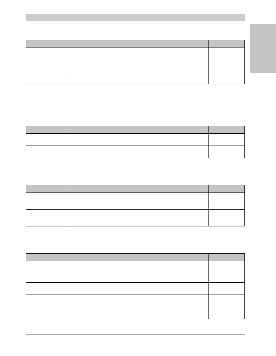
2.7.1 Separation of materials
It is necessary to separate different materials so the device can undergo an environmentallyfriendly recycling process.
.
Component Disposal
Programmable logic controllers
Operating and monitoring devices
Uninterruptible power supply
Cables
Cardboard box / paper packaging Paper / cardboard recycling
Plastic packaging Plastic recycling
Table 2: Environmentally-friendly separation of materials
Electronics recycling
Disposal must comply with the respective legal regulations.
22
Panel PC 800 User's Manual V 1.00
General information • Organization of safety notices
3. Organization of safety notices
The safety notices in this manual are organized as follows:
Safety notice Description
Danger! Disregarding the safety regulations and guidelines can be life-threatening.
Caution! Disregarding the safety regulations and guidelines can result in severe injury or major damage to material.
Warning! Disregarding the safety regulations and guidelines can result in injury or damage to material.
Information: Important information for preventing errors.
4. Directives
Section 1
General information
Table 3: Organization of safety notices
European dimension standards apply to all dimensions (e.g. dimension
diagrams, etc.).
23Panel PC 800 User's Manual V 1.00
General information • Model numbers
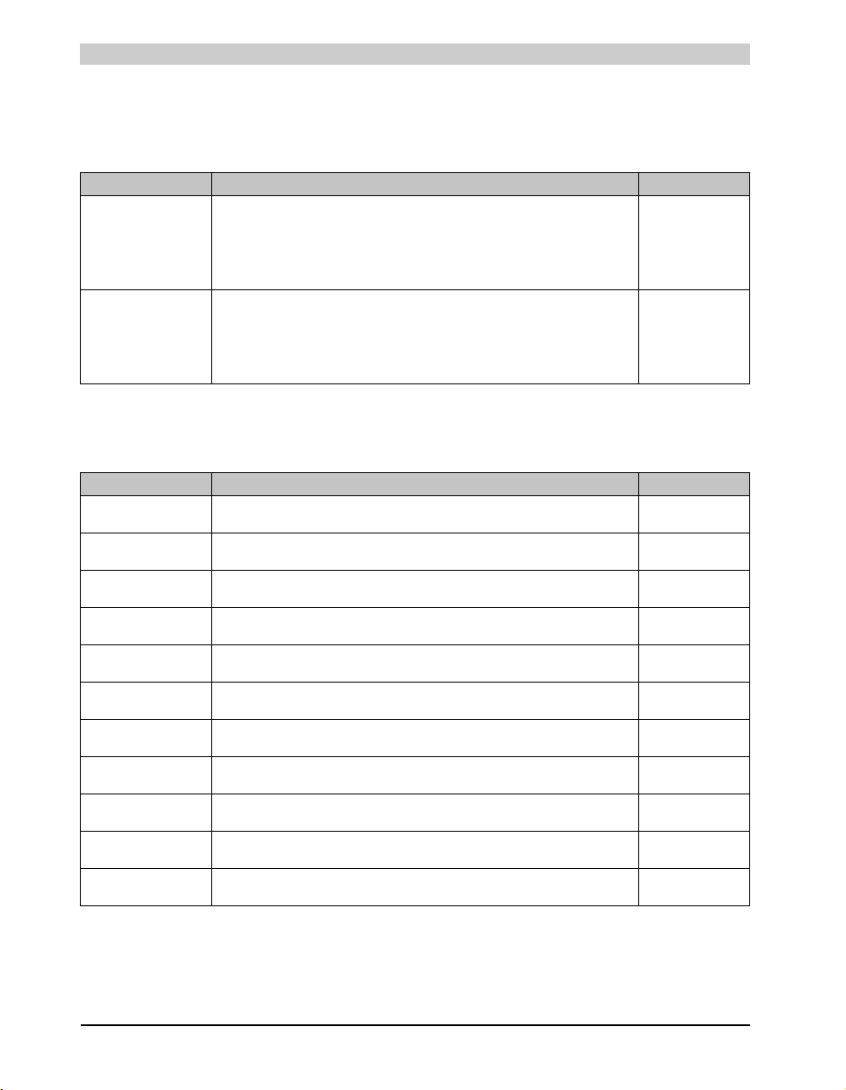
5. Model numbers
5.1 System units
Model number Short description Note
5PC820.1505-00 PPC820 TFT C XGA 15in T
5PC820.1906-00 PPC820 TFT C SXGA 19in T
5.2 CPU boards 945GME COM Express
Model number Short description Note
5PC800.B945-00 CPU board Intel® Core™ Duo L2400, 1.66 GHz
5PC800.B945-10 CPU board Intel® Core™ Duo L2400, 1.66 GHz /2
5PC800.B945-01 CPU board Intel® Core™2 Duo L7400, 1.5 GHz
5PC800.B945-11 CPU board Intel® Core™2 Duo L7400, 1.5 /2
5PC800.B945-02 CPU board Intel® Core™2 Duo U7500, 1.06 GHz
5PC800.B945-12 CPU board Intel® Core™2 Duo U7500, 1.06 GHz /2
5PC800.B945-03 CPU board Intel® Celeron® M 423, 1.06 GHz
5PC800.B945-13 CPU board Intel® Celeron® M 423, 1.06 GHz /2
5PC800.B945-04 CPU board Intel® Core™2 Duo T7400, 2.16 GHz
5PC800.B945-14 CPU board Intel® Core™2 Duo T7400, 2.16 GHz /2
5PC800.B945-05 CPU board Intel® Atom™ N270, 1.6 GHz
Panel PC 820 15" TFT display with touch screen (resistive); connections for 1x RS232, 5x
USB 2.0, Smart Display Link/DVI/monitor, 2x Ethernet 10/100/1000, HDA sound, add-on UPS
slot, expandable with 1 or 2 PCI / PCI Express slots, optional PCI Express compact and slidein compact slot; IP65 protection (front side); 24 VDC. Plug for power supply must be ordered
separately (screw clamps: 0TB103.9; cage clamps: 0TB103.91).
Panel PC 820 19" SXGA color TFT display with touch screen (resistive); connections for 1x
RS232, 5x USB 2.0, Smart Display Link/DVI/monitor, 2x Ethernet 10/100/1000, HDA sound,
add-on UPS slot, expandable with 1 or 2 PCI / PCI Express slots, optional PCI Express
compact and slide-in compact slot; IP65 protection (front side); 24 VDC. Plug for power
supply must be ordered separately (screw clamps: 0TB103.9; cage clamps: 0TB103.91).
Table 4: Model numbers - system units
667 MHz FSB, 2 MB L2 cache; 945GME chipset; 2 sockets for SO-DIMM DDR2 module
667 MHz FSB, 2 MB L2 cache; 945GME chipset; 2 sockets for SO-DIMM DDR2 module
667 MHz FSB, 2 MB L2 cache; 945GME chipset; 4 sockets for SO-DIMM DDR2 module
667 MHz FSB, 2 MB L2 cache; 945GME chipset; 4 sockets for SO-DIMM DDR2 module
533 MHz FSB, 2 MB L2 cache; 945GME chipset; 2 sockets for SO-DIMM DDR2 module
533 MHz FSB, 2 MB L2 cache; 945GME chipset; 2 sockets for SO-DIMM DDR2 module
533 MHz FSB, 2 MB L2 cache; 945GME chipset; 1 sockets for SO-DIMM DDR2 module
533 MHz FSB, 2 MB L2 cache; 945GME chipset; 1 sockets for SO-DIMM DDR2 module
667 MHz FSB, 2 MB L2 cache; 945GME chipset; 4 sockets for SO-DIMM DDR2 module
667 MHz FSB, 2 MB L2 cache; 945GME chipset; 4 sockets for SO-DIMM DDR2 module
533 MHz FSB, 512 kB L2 Cache; Chipset 945GME; 2 sockets for SO-DIMM DDR2 module
Table 5: Model numbers - CPU boards 945GME
See page 66
See page 72
See page 78
See page 78
See page 78
See page 78
See page 78
See page 78
See page 78
See page 78
See page 78
See page 78
See page 78
24
Panel PC 800 User's Manual V 1.00
General information • Model numbers
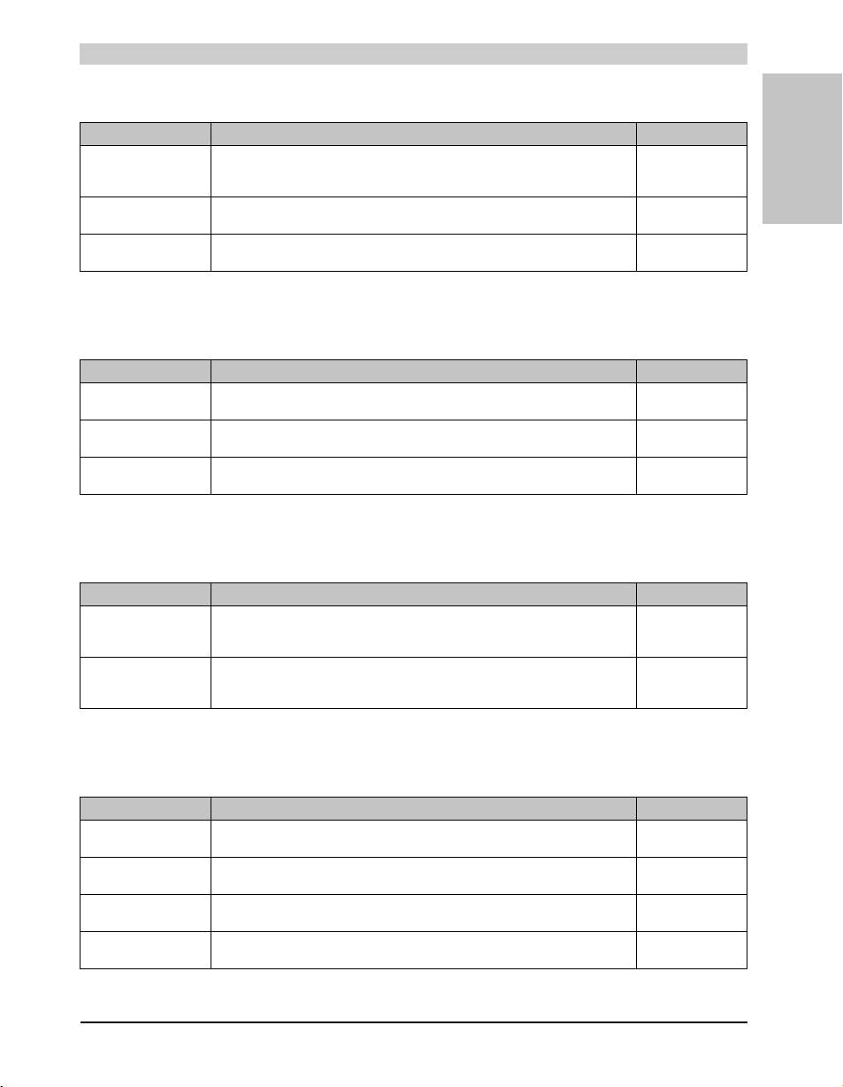
5.3 Heat sink
Model number Short description Note
5AC803.HS00-00 Panel PC 800 heat sink
5AC803.HS00-01 Panel PC 800 heat sink T7400
5AC803.HS00-02 Panel PC 800 heat sink 945GME N270
PPC800 heat sink for CPU boards with Dual Core processors L2400, L7400, U7500 and
Celeron M 423.
PPC800 heat sink for CPU board with Dual Core processor T7400.
PPC800 heat sink for CPU boards with Atom N270 processor and Chipset 945GME.
See page 79
See page 79
See page 79
Table 6: Model numbers - Heat sinks
5.4 Main memory
Model number Short description Note
5MMDDR.0512-01 SO-DIMM DDR2 512MB PC2-5300
5MMDDR.1024-01 SO-DIMM DDR2 1024MB PC2-5300 See page 80
5MMDDR.2048-01 SO-DIMM DDR2 2048MB PC2-5300 See page 80
See page 80
Table 7: Model numbers - Main memory
5.5 Expansion
Section 1
General information
Model number Short description Note
5AC803.SX01-00 PPC800 Expansion 1CS 1SI
5AC803.SX02-00 PPC800 Expansion 2CS 1SI
PPC800 expansion 1 PCI/PCI Express and 1 slide-in (bus 5AC803.BX01-00 or
5AC803.BX01-01 required).
PPC800 expansion 2 PCI/PCI Express and 1 slide-in (bus 5AC803.BX02-00 or
5AC803.BX02-01 required).
See page 81
See page 81
Table 8: Model numbers - Expansion
5.6 Bus units
Model number Short description Note
5AC803.BX01-00 PPC800 bus 1PCI 1SI
5AC803.BX01-01 PPC800 bus 1PCIe.x1 1SI
5AC803.BX02-00 PPC800 bus 2PCI 1SI
5AC803.BX02-01 PPC800 bus 1PCI 1PCIe.x1 1SI
PPC800 bus 1 PCI, 1 slide-in slot.
PPC800 bus 1 PCI Express, 1 slide-in slot.
PPPC800 bus 2 PCI, 1 slide-in slot.
PPC800 bus 1 PCI, 1 PCI Express, 1 slide-in slot.
Table 9: Model numbers - bus units
See page 86
See page 86
See page 86
See page 86
25Panel PC 800 User's Manual V 1.00
General information • Model numbers
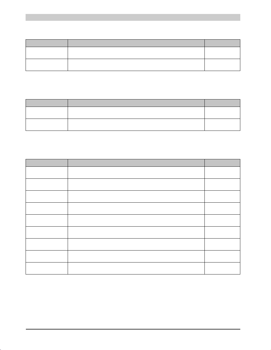
5.7 Option
Model number Short description Note
5AC803.BC01-00 PPC800 option PCI Express compact
PPC800 option for expanding a PCIec card in the system unit.
5AC803.BC02-00 PPC800 option slide-in compact
PPC800 option for expanding a slide-in compact drive in the system unit.
See page 88
See page 88
Table 10: Model numbers - Option
5.8 Plug-in cards
Model number Short description Note
5ACPCC.ETH0-00 PCIec Ethernet card 10/100/1000
PCIec Ethernet plug-in card, 1 Ethernet interface 10/100/1000
5ACPCC.MPL0-00 PCIec POWERLINK MN 2-port
PCIec POWERLINK plug-in card, 2 POWERLINK interfaces
See page 90
See page 92
Table 11: Model numbers - Drives
5.9 Drives
Model number Short description Note
5AC801.ADAS-00 APC810 slide-in compact adapter
5AC801.HDDI-00 APC810 slide-in compact HDD 40GB
5AC801.HDDI-02 APC810 slide-in compact HDD 160GB 24x7 ET
5AC801.HDDS-00 APC810 slide-in HDD 40GB
5AC801.SSDI-00 APC8 10 slide-in compact HDD 32GB (SLC)
5AC801.DVDS-00 APC810 slide-in DVD-ROM
5AC801.DVRS-00 APC810 slide-in DVD-R/RW
5ACPCI.RAIC-03 PCI SATA RAID System 2x160 GB
5ACPCI.RAIC-04 Replacement SATA-HDD 160GB
Adapter for operating compact slide-in drives in a slide-in slot drive slot.
40 GB SATA hard disk (slide-in compact), 24/7 hard disk with extended temperature range.
160 GB SATA hard disk (slide-in compact), 24/7 hard disk with extended temperature range.
40 GB SATA hard disk (slide-in), 24/7 hard disk with extended temperature range.
32 GB SSD drive (slide-in)
DVD-ROM drive (slide-in)
DVD-R/RW, DVD+R/RW drive (slide-in)
PCI RAID controller + 2 x 160 GB SATA hard disks; requires a free PCI slot.
Hard disk 160 GB SATA, replacement part for 5ACPCI.RAIC-03
Table 12: Model numbers - Drives
See page 105
See page 95
See page 98
See page 106
See page 101
See page 109
See page 112
See page 116
See page 121
26
Panel PC 800 User's Manual V 1.00
General information • Model numbers
5.10 Fan kits
Model number Short description Note
5AC803.FA01-00 PPC800 fan kit 1CS
APC800 fan kit for system units without an expansion.
5AC803.FA02-00 PPC800 fan kit 2CS
APC800 fan kit for system units with expansion 5AC803.SX01-00.
5AC803.FA03-00 PPC800 fan kit 3CS
APC800 fan kit for system units with expansion 5AC803.SX02-00.
See page 124
See page 125
See page 126
Table 13: Model numbers - Fan kits
5.11 Accessories
5.11.1 Batteries
Model number Short description Note
0AC201.91 Lithiu m batteries, 4 pcs.
4A0006.00-000 Lithium battery, 1 pc.
Lithium batteries, 4 pcs., 3 V / 950 mAh, button cell
Lithium battery, 1 pc., 3 V / 950 mAh, button cell
Table 14: Model numbers - Batteries
5.11.2 Supply voltage connectors
See page 294
See page 294
Section 1
General information
Model number Short description Note
0TB103.9 Plug 24V 5.08 3-pin screw clamps
0TB103.91 Plug 24V 5.08 3-pin cage clamps
24 VDC 3-pin connector, female. Screw clamp, 3.31 mm², protected against vibration by the
screw flange.
24 VDC 3-pin connector, female. Cage clamps, 3.31 mm², protected against vibration by the
screw flange.
See page 296
See page 296
Table 15: Model numbers - Supply voltage connectors
5.11.3 UPS module + accessories
Model number Short description Note
5AC600.UPSI-00 Add-on UPS module
5AC600.UPSB-00 Battery unit 5 Ah
5CAUPS.0005-00 0.5 m APC620 UPS cable
5CAUPS.0030-00 3 m APC620 UPS cable
UPS module for APC620 / APC810 / PPC800 system units.
Order cable (5CAUPS.0005-00 or 5CAUPS.0030-00) and battery unit (5AC600.UPSB-00)
separately.
UPS battery unit for the add-on UPS module
Connection cable between add-on UPS module and UPS battery unit, length 0.5 meters
Connection cable between add-on UPS module and UPS battery unit, length 3 meters
Table 16: Model numbers - UPS module + accessories
See page 300
See page 300
See page 300
See page 300
27Panel PC 800 User's Manual V 1.00

General information • Model numbers
5.11.4 External UPS
Model number Short description Note
9A0100.11 UPS 24 VDC
9A0100.14 UPS battery unit type B
9A0100.15 UPS battery unit type B (replacement part)
9A0017.01 RS232 Null Modem Cable, 0.6 m
9A0017.02 RS232 Null Modem Cable, 1.8 m
24 VDC input, 24 VDC output, serial interface
24 V; 2.2 Ah; including battery cage
2 x 12 V; 2.2 Ah; for battery unit 9A0100.14
To connect UPS and load system (9-pin DSUB socket - 9-pin DSUB socket)
To connect UPS and load system (9-pin DSUB socket - 9-pin DSUB socket)
See page 309
See page 309
See page 309
See page 309
See page 309
Table 17: Model numbers - External UPS
5.11.5 CompactFlash cards
Model number Short description Note
5CFCRD.0512-04 CompactFlash 512 MB B&R
5CFCRD.1024-04 CompactFlash 1024 MB B&R
5CFCRD.2048-04 CompactFlash 2048 MB B&R
5CFCRD.4096-04 CompactFlash 4096 MB B&R
5CFCRD.8192-04 CompactFlash 8192 MB B&R
5CFCRD.016G-04 16 GB B&R CompactFlash card
5CFCRD.0064-03 CompactFlash 64 MB SSI
5CFCRD.0128-03 CompactFlash 128 MB SSI
5CFCRD.0256-03 CompactFlash 256 MB SSI
5CFCRD.0512-03 CompactFlash 512 MB SSI
5CFCRD.1024-03 CompactFlash 1024 MB SSI
5CFCRD.2048-03 CompactFlash 2048 MB SSI
5CFCRD.4096-03 CompactFlash 4096 MB SSI
5CFCRD.8192-03 CompactFlash 8192 MB SSI
CompactFlash card with 512 MB SLC NAND flash and IDE/ATA interface
CompactFlash card with 1024 MB SLC NAND flash and IDE/ATA interface
CompactFlash card with 2048 MB SLC NAND flash and IDE/ATA interface
CompactFlash card with 4096 MB SLC NAND flash and IDE/ATA interface
CompactFlash card with 8192 MB SLC NAND flash and IDE/ATA interface
CompactFlash card with 16 GB SLC NAND flash and IDE/ATA interface
CompactFlash card with 64 MB SLC NAND flash and IDE/ATA interface
CompactFlash card with 128 MB SLC NAND flash and IDE/ATA interface
CompactFlash card with 256 MB SLC NAND flash and IDE/ATA interface
CompactFlash card with 512 MB SLC NAND flash and IDE/ATA interface
CompactFlash card with 1024 MB SLC NAND flash and IDE/ATA interface
CompactFlash card with 2048 MB SLC NAND flash and IDE/ATA interface
CompactFlash card with 4096 MB SLC NAND flash and IDE/ATA interface
CompactFlash card with 8192 MB SLC NAND flash and IDE/ATA interface
Table 18: Model numbers - CompactFlash cards
See page 311
See page 311
See page 311
See page 311
See page 311
See page 311
See page 316
See page 316
See page 316
See page 316
See page 316
See page 316
See page 316
See page 316
28
Panel PC 800 User's Manual V 1.00

General information • Model numbers
5.11.6 USB flash drives
Model number Short description Note
5MMUSB.2048-00 USB flash drive 2 GB SanDisk
USB 2.0 flash drive 2 GB
See page 320
Table 19: Model numbers - USB flash drives
5.11.7 Cables
Model number Short description Note
5CADVI.0018-00 DVI-D cable 1.8 m
5CADVI.0050-00 DVI-D cable 5 m
5CADVI.0100-00 DVI-D cable 10 m
5CASDL.0018-00 SDL cable 1.8 m
5CASDL.0018-01 SDL cable 1.8 m 45°
5CASDL.0018-03 SDL flex cable 1.8 m
5CASDL.0050-00 SDL cable 5 m
5CASDL.0050-01 SDL cable 5 m 45°
5CASDL.0050-03 5 m flex SDL cable
5CASDL.0100-00 SDL cable 10 m
5CASDL.0100-01 SDL cable 10 m 45°
5CASDL.0100-03 10 m flex SDL cable
5CASDL.0150-00 SDL cable 15 m
5CASDL.0150-01 SDL cable 15 m 45°
5CASDL.0150-03 15 m flex SDL cable
5CASDL.0200-00 SDL cable 20 m
5CASDL.0200-03 20 m flex SDL cable
5CASDL.0250-00 SDL cable 25 m
Single cable, DVI-D/m:DVI-D/m; length: 1.8 m
Single cable, DVI-D/m:DVI-D/m; length: 5 m
Single cable, DVI-D/m:DVI-D/m; length: 10 m
SDL cable for a fixed type of layout; length: 1.8 m
SDL cable for fixed type of layout with one-sided 45° plug; length: 1.8 m
SDL cable for fixed and flexible type of layout; length: 1.8 m
SDL cable for a fixed type of layout; length: 5 m
SDL cable for fixed type of layout with one-sided 45° plug; length: 5 m
SDL cable for fixed and flexible type of layout; length: 5 m
SDL cable for a fixed type of layout; length: 10 m
SDL cable for fixed type of layout with one-sided 45° plug; length: 10 m
SDL cable for fixed and flexible type of layout; length: 10 m
SDL cable for a fixed type of layout; length: 15 m
SDL cable for fixed type of layout with one-sided 45° plug; length: 15 m
SDL cable for fixed and flexible type of layout; length: 15 m
SDL cable for a fixed type of layout; length: 20 m
SDL cable for fixed and flexible type of layout; length: 20 m
SDL cable for a fixed type of layout; length: 25 m
Table 20: Model numbers - Cables
See page 327
See page 327
See page 327
See page 330
See page 333
See page 336
See page 330
See page 333
See page 336
See page 330
See page 333
See page 336
See page 330
See page 333
See page 336
See page 330
See page 336
See page 330
Section 1
General information
29Panel PC 800 User's Manual V 1.00
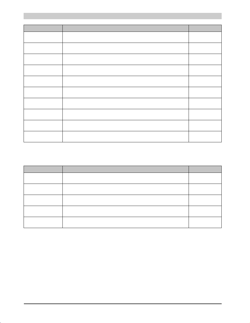
General information • Model numbers
Model number Short description Note
5CASDL.0250-03 25 m flex SDL cable
5CASDL.0300-00 SDL cable 30 m
5CASDL.0300-03 30 m flex SDL cable
5CASDL.0300-13 30 m SDL flex cable with extender
5CASDL.0400-13 40 m SDL flex cable with extender
5CAUSB.0018-00 USB 2.0 cable, A/m:B/m 1.8 m
5CAUSB.0050-00 USB 2.0 cable, A/m:B/m 5 m
9A0014.02 RS232 cable DB9/f:DB9/m 1.8 m
9A0014.05 RS232 cable DB9/f:DB9/m 5 m
9A0014.10 RS232 cable DB9/f:DB9/m 10 m
SDL cable for fixed and flexible type of layout; length: 25 m
SDL cable for a fixed type of layout; length: 30 m
SDL cable for fixed and flexible type of layout; length: 30 m
SDL cable with extender for fixed and flexible type of layout; length: 30 m
SDL cable with extender for fixed and flexible type of layout; length: 40 m
USB 2.0 connection cable; plug type A - type B; length 1.8 m
USB 2.0 connection cable; plug type A - type B; length 5 m
RS232 extension cable for remote operation of a display unit with touch screen; length 1.8 m.
RS232 extension cable for remote operation of a display unit with touch screen; length 5 m.
RS232 extension cable for remote operation of a display unit with touch screen; length 10 m.
See page 336
See page 330
See page 336
See page 341
See page 341
See page 348
See page 348
See page 346
See page 346
See page 346
Table 20: Model numbers - Cables (cont.)
5.11.8 Miscellaneous
Model number Short description Note
5AC900.1000-00 Adapter DVI-A/m to CRT DB15HD/f
5AC900.1200-01 USB port cap IP65 M20 /2
5AC900.1200-02 USB port cap IP65 M20 /3
5AC900.1200-03 USB port cap IP65 M20 /4
1A4300.LZ1U B&R Automation Studio 3.0 USB dongle
Adapter DVI (plug) to CRT (socket), for connecting a standard monitor to a DVI-I interface.
Front-side USB port cap (attached) knurled, short, not slotted.
Front-side USB port cap (attached) knurled, tall, not slotted.
Front-side USB port cap (attached) knurled, tall, slotted.
Dongle for using AR010.
See page 298
See page 299
See page 299
See page 299
See page 323
Table 21: Model numbers - Other items
30
Panel PC 800 User's Manual V 1.00
 Loading...