

Page 1

Panel PC 800
User's Manual
Version: 1.00 (Mai 2010)
Model number: MAPPC800-ENG
All information contained in this manual is current as of its creation/publication. We reserve the
right to change the contents of this manual without warning. The information contained herein is
believed to be accurate as of the date of publication; however, Bernecker + Rainer IndustrieElektronik Ges.m.b.H. makes no warranty, expressed or implied, with regards to the products or
the documentation contained within this book. In addition, Bernecker + Rainer IndustrieElektronik Ges.m.b.H. shall not be liable in the event of incidental or consequential damages in
connection with or resulting from the furnishing, performance, or use of these products. The
software names, hardware names, and trademarks used in this manual are registered by the
respective companies.
1Panel PC 800 User's Manual V 1.00
Page 2

2 Panel PC 800 User's Manual V 1.00 3Panel PC 800 User's Manual V 1.00
Page 3

Chapter 1: General information
Chapter 2: Technical data
Chapter 3: Commissioning
Chapter 4: Software
Chapter 5: Standards and certifications
Chapter 6: Accessories
Page 4

4 Panel PC 800 User's Manual V 1.00 5Panel PC 800 User's Manual V 1.00
Page 5

Chapter 7: Maintenance / Servicing
Appendix A
Figure index
Table index
Model number index
Index
Page 6

6 Panel PC 800 User's Manual V 1.00
Page 7

Table of contents
Chapter 1: General information ..................................................... 17
1. Manual history .................................................................................................................... 17
2. Safety notices ..................................................................................................................... 19
2.1 Intended use .................................................................................................................. 19
2.2 Protection against electrostatic discharges ................................................................... 19
2.2.1 Packaging ............................................................................................................... 19
2.2.2 Guidelines for proper ESD handling ....................................................................... 19
2.3 Policy and procedures ................................................................................................... 20
2.4 Transport and storage ................................................................................................... 20
2.5 Installation ..................................................................................................................... 21
2.6 Operation ....................................................................................................................... 21
2.6.1 Protection against touching electrical parts ............................................................ 21
2.6.2 Environmental conditions - dust, humidity, aggressive gases ................................ 21
2.6.3 Programs, viruses, and dangerous programs ......................................................... 22
2.7 Environmentally-friendly disposal .................................................................................. 22
2.7.1 Separation of materials ........................................................................................... 22
3. Organization of safety notices ............................................................................................ 23
4. Directives ............................................................................................................................ 23
5. Model numbers ................................................................................................................... 24
5.1 System units .................................................................................................................. 24
5.2 CPU boards 945GME COM Express ............................................................................ 24
5.3 Heat sink ....................................................................................................................... 25
5.4 Main memory ................................................................................................................. 25
5.5 Expansion ...................................................................................................................... 25
5.6 Bus units ........................................................................................................................ 25
5.7 Option ............................................................................................................................ 26
5.8 Plug-in cards ................................................................................................................. 26
5.9 Drives ............................................................................................................................ 26
5.10 Fan kits ........................................................................................................................ 27
5.11 Accessories ................................................................................................................. 27
5.11.1 Batteries ................................................................................................................ 27
5.11.2 Supply voltage connectors .................................................................................... 27
5.11.3 UPS module + accessories ................................................................................... 27
5.11.4 External UPS ........................................................................................................ 28
5.11.5 CompactFlash cards ............................................................................................. 28
5.11.6 USB flash drives ................................................................................................... 29
5.11.7 Cables ................................................................................................................... 29
5.11.8 Miscellaneous ....................................................................................................... 30
5.12 Software ...................................................................................................................... 31
Chapter 2: Technical data .............................................................. 33
1. Introduction ......................................................................................................................... 33
1.1 Features ........................................................................................................................ 34
1.2 System components / Configuration ............................................................................. 35
1.2.1 Configuration - Basic system .................................................................................. 35
1.2.2 Configuration - Optional components ..................................................................... 36
7Panel PC 800 User's Manual V 1.00
Page 8

Table of contents
2. Entire device ....................................................................................................................... 37
2.1 Temperature specifications ........................................................................................... 37
2.1.1 Maximum ambient temperature .............................................................................. 38
2.1.2 Minimum ambient temperature ............................................................................... 39
2.1.3 How do you determine the maximum ambient temperature? ................................. 40
2.1.4 Temperature monitoring .......................................................................................... 40
2.2 Humidity specifications .................................................................................................. 41
2.3 Power management ...................................................................................................... 42
2.3.1 Block diagram - supply voltage ............................................................................... 42
2.3.2 Power calculation with 5PC820.1505-00 ................................................................ 43
2.3.3 Power calculation with 5PC820.1906-00 ................................................................ 44
2.4 Block diagram ................................................................................................................ 45
2.5 Serial number sticker ..................................................................................................... 46
2.6 Device interfaces ........................................................................................................... 48
2.6.1 +24 VDC supply voltage ......................................................................................... 48
2.6.2 Monitor / Panel connection - SDL (Smart Display Link / DVI) ................................. 50
2.6.3 Serial interface COM1 ............................................................................................. 51
2.6.4 Ethernet 1 (ETH1) ................................................................................................... 52
2.6.5 Ethernet 2 (ETH2) ................................................................................................... 53
2.6.6 USB interfaces (USB1, 2, 3, 4) ............................................................................... 54
2.6.7 MIC, Line IN, Line OUT ........................................................................................... 56
2.6.8 Add-on UPS slot ..................................................................................................... 57
2.6.9 Status LEDs ............................................................................................................ 58
2.6.10 CMOS profile switch ............................................................................................. 59
2.6.11 Power button ......................................................................................................... 60
2.6.12 Reset button .......................................................................................................... 60
2.6.13 Battery ................................................................................................................... 61
2.6.14 CompactFlash slot 1 ............................................................................................. 62
2.6.15 CompactFlash slot 2 ............................................................................................. 63
2.6.16 Slide-in compact slot ............................................................................................. 64
2.6.17 PCIec slot (card slot) ............................................................................................. 65
3. Individual components ........................................................................................................ 66
3.1 System units .................................................................................................................. 66
3.1.1 Panel PC 5PC820.1505-00 ..................................................................................... 66
3.1.2 Panel PC 5PC820.1906-00 ..................................................................................... 72
3.2 CPU boards 945GME .................................................................................................... 78
3.2.1 Technical data ......................................................................................................... 78
3.3 Heat sink ....................................................................................................................... 79
3.3.1 Technical data ......................................................................................................... 79
3.4 Main memory ................................................................................................................. 80
3.4.1 Technical data ......................................................................................................... 80
3.5 Expansion ...................................................................................................................... 81
3.5.1 Technical data ......................................................................................................... 82
3.5.2 Dimensions - 5PC803.SX01-00 .............................................................................. 82
3.5.3 Dimensions - 5PC803.SX02-00 .............................................................................. 83
3.5.4 Slot for bus units ..................................................................................................... 84
3.5.5 Slide-in slot 1 .......................................................................................................... 85
8 Panel PC 800 User's Manual V 1.00
Page 9

Table of contents
3.6 Bus units ........................................................................................................................ 86
3.6.1 Technical data ......................................................................................................... 87
3.7 Option ............................................................................................................................ 88
3.8 Plug-in cards ................................................................................................................. 89
3.8.1 Ethernet Card 10/100/1000 - 5ACPCC.ETH0-00 ................................................... 90
3.8.2 POWERLINK card 2-port - 5ACPCC.MPL0-00 ....................................................... 92
3.9 Drives ............................................................................................................................ 95
3.9.1 Slide-in compact HDD 40GB EE25 - 5AC801.HDDI-00 ......................................... 95
3.9.2 Slide-in compact HDD 160 GB 24x7 ET - 5AC801.HDDI-02 .................................. 98
3.9.3 Slide-in compact SSD - 5AC801.SSDI-00 ............................................................ 101
3.9.4 Hard disk adapter (slide-in compact) - 5AC801.ADAS-00 .................................... 105
3.9.5 Slide-in HDD EE25 - 5AC801.HDDS-00 ............................................................... 106
3.9.6 Slide-in DVD-ROM - 5AC801.DVDS-00 ............................................................... 109
3.9.7 Slide-in DVD-R/RW - 5AC801.DVRS-00 .............................................................. 112
3.9.8 PCI SATA RAID 2 x 160 GB 24x7 ET - 5ACPCI.RAIC-03 .................................... 116
3.9.9 Replacement PCI SATA RAID HDD 160 GB - 5ACPCI.RAIC-04 ......................... 121
3.10 Fan kits ...................................................................................................................... 124
3.10.1 Fan kit 1 card slot - 5AC803.FA01-00 ................................................................. 124
3.10.2 Fan kit 2 card slot - 5AC803.FA02-00 ................................................................. 125
3.10.3 Fan kit 3 card slot - 5AC803.FA03-00 ................................................................. 126
Chapter 3: Commissioning .......................................................... 127
1. Installation ......................................................................................................................... 127
1.1 Important mounting information ................................................................................... 128
1.2 Mounting orientation .................................................................................................... 129
1.2.1 Standard mounting ................................................................................................ 129
1.2.2 Standard mounting with 5AC801.DVRS-00 .......................................................... 130
1.2.3 Standard mounting with 5AC801.DVDS-00 .......................................................... 131
1.2.4 Spacing for air circulation. ..................................................................................... 132
2. Cable connections ............................................................................................................ 133
3. Grounding concept ........................................................................................................... 134
4. Connection examples ....................................................................................................... 135
4.1 Selecting the display units ........................................................................................... 135
4.2 One Automation Panel 900 via DVI ............................................................................. 136
4.2.1 Basic system requirements ................................................................................... 136
4.2.2 Link modules ......................................................................................................... 137
4.2.3 Cables ................................................................................................................... 137
4.2.4 Possible Automation Panel units, resolutions und segment lengths ..................... 137
4.2.5 BIOS settings ........................................................................................................ 138
4.3 One Automation Panel 900 via SDL ............................................................................ 139
4.3.1 Basic system requirements ................................................................................... 139
4.3.2 Link modules ......................................................................................................... 140
4.3.3 Cables ................................................................................................................... 140
4.3.4 BIOS settings ........................................................................................................ 141
4.4 One Automation Panel 800 via SDL ............................................................................ 142
4.4.1 Basic system requirements ................................................................................... 142
9Panel PC 800 User's Manual V 1.00
Page 10

Table of contents
4.4.2 Cables ................................................................................................................... 143
4.4.3 BIOS settings ........................................................................................................ 144
4.5 One AP900 and one AP800 via SDL .......................................................................... 145
4.5.1 Basic system requirements ................................................................................... 145
4.5.2 Link modules ......................................................................................................... 146
4.5.3 Cables ................................................................................................................... 146
4.5.4 BIOS settings ........................................................................................................ 146
4.6 Four Automation Panel 900 units via SDL .................................................................. 147
4.6.1 Basic system requirements ................................................................................... 147
4.6.2 Link modules ......................................................................................................... 148
4.6.3 Cables ................................................................................................................... 148
4.6.4 BIOS settings ........................................................................................................ 150
5. Touch screen calibration ................................................................................................... 151
5.1 Windows XP Professional ........................................................................................... 151
5.2 Windows CE ................................................................................................................ 151
5.3 Windows XP Embedded .............................................................................................. 151
5.4 Windows Embedded Standard 2009 ........................................................................... 151
5.5 Automation Runtime / Visual Components .................................................................. 151
6. Connection of USB peripheral devices ............................................................................. 152
6.1 Locally on the PPC800 ................................................................................................ 152
6.2 Remote connection to Automation Panel 900 via DVI ................................................ 153
6.3 Remote connection to Automation Panel 800/900 via SDL ........................................ 154
7. Configuration of a SATA RAID array ................................................................................ 155
7.1 Create RAID set .......................................................................................................... 156
7.1.1 Create RAID set - Striped ..................................................................................... 157
7.1.2 Create RAID set - Mirrored ................................................................................... 158
7.2 Delete RAID set ........................................................................................................... 159
7.3 Rebuild mirrored set .................................................................................................... 160
7.4 Resolve conflicts ......................................................................................................... 161
7.5 Low level format .......................................................................................................... 162
8. Known problems / issues .................................................................................................. 163
9. User tips for increasing the display lifespan ..................................................................... 164
9.1 Backlight ...................................................................................................................... 164
9.1.1 How can the lifespan of backlights be extended? ................................................. 164
9.2 Image sticking ............................................................................................................. 164
9.2.1 What causes image sticking? ............................................................................... 164
9.2.2 How can image sticking be avoided? .................................................................... 165
Chapter 4: Software ...................................................................... 167
1. BIOS options ..................................................................................................................... 167
1.1 General information ..................................................................................................... 167
1.2 BIOS setup and boot procedure .................................................................................. 167
1.2.1 BIOS setup keys ................................................................................................... 168
1.3 Main ............................................................................................................................. 170
1.4 Advanced .................................................................................................................... 171
1.4.1 ACPI configuration ................................................................................................ 173
10 Panel PC 800 User's Manual V 1.00
Page 11

Table of contents
1.4.2 PCI Configuration .................................................................................................. 175
1.4.3 PCI express configuration ..................................................................................... 179
1.4.4 Graphics configuration .......................................................................................... 181
1.4.5 CPU configuration ................................................................................................. 185
1.4.6 Chipset configuration ............................................................................................ 186
1.4.7 I/O interface configuration ..................................................................................... 188
1.4.8 Clock Configuration ............................................................................................... 189
1.4.9 IDE Configuration .................................................................................................. 190
1.4.10 USB configuration ............................................................................................... 198
1.4.11 Keyboard/mouse configuration ........................................................................... 200
1.4.12 Remote access configuration .............................................................................. 201
1.4.13 CPU board monitor ............................................................................................. 203
1.4.14 Main Board/Panel Features ................................................................................ 204
1.5 Boot ............................................................................................................................. 210
1.6 Security ....................................................................................................................... 212
1.6.1 Hard disk security user password ......................................................................... 213
1.6.2 Hard disk security master password ..................................................................... 214
1.7 Power .......................................................................................................................... 215
1.8 Exit .............................................................................................................................. 217
1.9 BIOS default settings ................................................................................................... 217
1.9.1 Main ...................................................................................................................... 219
1.9.2 Advanced .............................................................................................................. 219
1.9.3 Boot ....................................................................................................................... 226
1.9.4 Security ................................................................................................................. 227
1.9.5 Power .................................................................................................................... 227
1.10 BIOS Error signals (beep codes) ............................................................................... 228
1.10.1 BIOS 945GME .................................................................................................... 228
1.11 Distribution of resources ............................................................................................ 229
1.11.1 RAM address assignment ................................................................................... 229
1.11.2 I/O address assignment ...................................................................................... 230
1.11.3 Interrupt assignments in PCI mode ..................................................................... 231
1.11.4 Interrupt assignments in APCI mode .................................................................. 232
2. Upgrade information ......................................................................................................... 234
2.1 BIOS upgrade .............................................................................................................. 234
2.1.1 What information do I need? ................................................................................. 234
2.1.2 BIOS upgrade for 945GME COM Express ........................................................... 237
2.2 Firmware upgrade ....................................................................................................... 238
2.2.1 Procedure ............................................................................................................. 238
2.2.2 Possible upgrade problems and software dependencies (for V1.02) ................... 240
2.3 Creating an MS-DOS boot diskette in Windows XP .................................................... 241
2.4 Creating a bootable USB flash drive for B&R upgrade files ........................................ 243
2.4.1 Requirements ........................................................................................................ 243
2.4.2 Procedure ............................................................................................................. 243
2.4.3 Where do I get MS-DOS? ..................................................................................... 244
2.5 Creating a bootable CompactFlash card for B&R upgrade files .................................. 245
2.5.1 Requirements ........................................................................................................ 245
2.5.2 Procedure ............................................................................................................. 245
11Panel PC 800 User's Manual V 1.00
Page 12

Table of contents
2.5.3 Where do I get MS-DOS? ..................................................................................... 246
2.6 Upgrade problems ....................................................................................................... 246
3. Panel PC 800 with MS-DOS ............................................................................................. 247
3.1 Known problems .......................................................................................................... 247
4. Panel PC 800 with Windows XP Professional .................................................................. 249
4.1 Installation ................................................................................................................... 249
5. Panel PC 800 with Windows XP Embedded .................................................................... 250
5.1 General information ..................................................................................................... 250
5.2 Features with FP2007 (Feature Pack 2007) ............................................................... 251
5.3 Installation ................................................................................................................... 252
5.4 Drivers ......................................................................................................................... 252
5.4.1 Touch screen driver .............................................................................................. 252
6. Panel PC 800 with Windows Embedded Standard 2009 .................................................. 253
6.1 General information ..................................................................................................... 253
6.2 Features with WES2009 (Windows Embedded Standard 2009) ................................. 254
6.3 Installation ................................................................................................................... 255
6.4 Drivers ......................................................................................................................... 255
6.4.1 Touch screen driver .............................................................................................. 255
7. Panel PC 800 with Automation Runtime ........................................................................... 256
7.1 General information ..................................................................................................... 256
7.2 AR010 ......................................................................................................................... 256
8. Automation Device Interface (ADI) - Control Center ......................................................... 257
8.1 Function ....................................................................................................................... 257
8.2 Installation ................................................................................................................... 259
8.3 SDL equalizer setting .................................................................................................. 260
8.4 UPS configuration ....................................................................................................... 261
8.4.1 Installing the UPS service for the B&R APC add-on UPS .................................... 262
8.4.2 Displaying UPS status values ............................................................................... 262
8.4.3 Changing UPS battery settings ............................................................................. 264
8.4.4 Updating UPS battery settings .............................................................................. 265
8.4.5 Saving UPS battery settings ................................................................................. 266
8.4.6 Configuring UPS system settings ......................................................................... 266
8.4.7 Changing additional UPS settings ........................................................................ 268
Chapter 5: Standards and certifications ..................................... 271
1. Applicable European guidelines ....................................................................................... 271
2. Overview of standards ...................................................................................................... 271
3. Emission requirements (emission) .................................................................................... 273
3.1 Network-related emissions .......................................................................................... 274
3.2 Emissions, electromagnetic emissions ........................................................................ 275
4. Requirements for immunity to disturbances (immunity) .................................................... 276
4.1 Electrostatic discharge (ESD) ..................................................................................... 277
4.2 High-frequency electromagnetic fields (HF field) ........................................................ 277
4.3 High-speed transient electrical disturbances (burst) ................................................... 278
4.4 Surges (surge) ............................................................................................................. 278
4.5 Conducted disturbances .............................................................................................. 279
12 Panel PC 800 User's Manual V 1.00
Page 13

Table of contents
4.6 Magnetic fields with electrical frequencies .................................................................. 279
4.7 Voltage dips, fluctuations and short-term interruptions ............................................... 279
4.8 Damped oscillatory waves ........................................................................................... 280
5. Mechanical conditions ...................................................................................................... 281
5.1 Vibration operation ...................................................................................................... 281
5.2 Vibration during transport (packaged) ......................................................................... 282
5.3 Shock during operation ............................................................................................... 282
5.4 Shock during transport (packaged) ............................................................................. 282
5.5 Toppling ....................................................................................................................... 282
5.6 Free fall (packaged) .................................................................................................... 283
6. Climate conditions ............................................................................................................ 284
6.1 Worst case operation .................................................................................................. 284
6.2 Dry heat ....................................................................................................................... 284
6.3 Dry cold ....................................................................................................................... 284
6.4 Large temperature fluctuations .................................................................................... 285
6.5 Temperature fluctuations in operation ......................................................................... 285
6.6 Humid heat, cyclic ....................................................................................................... 285
6.7 Humid heat, constant (storage) ................................................................................... 285
7. Safety ................................................................................................................................ 286
7.1 Ground resistance ....................................................................................................... 286
7.2 Insulation resistance .................................................................................................... 287
7.3 High voltage ................................................................................................................ 287
7.4 Residual voltage .......................................................................................................... 287
7.5 Leakage current .......................................................................................................... 288
7.6 Overload ...................................................................................................................... 288
7.7 Defective component ................................................................................................... 288
7.8 Voltage range .............................................................................................................. 288
8. Other tests ........................................................................................................................ 289
8.1 Protection type ............................................................................................................ 289
9. International certifications ................................................................................................. 290
Chapter 6: Accessories ................................................................ 291
1. Overview ........................................................................................................................... 291
2. Replacement CMOS batteries .......................................................................................... 294
2.1 Order data ................................................................................................................... 294
2.2 Technical data ............................................................................................................. 294
3. Supply voltage connector (TB103 3-pin) .......................................................................... 296
3.1 General information ..................................................................................................... 296
3.2 Order data ................................................................................................................... 296
3.3 Technical data ............................................................................................................. 296
4. DVI - monitor adapter 5AC900.1000-00 ........................................................................... 298
4.1 Order data ................................................................................................................... 298
5. USB interface cover (attached) ......................................................................................... 299
5.1 Order data ................................................................................................................... 299
6. Uninterruptible power supply ............................................................................................ 300
6.1 Features ...................................................................................................................... 301
13Panel PC 800 User's Manual V 1.00
Page 14

Table of contents
6.2 Requirements .............................................................................................................. 301
6.3 Individual components ................................................................................................. 302
6.3.1 Add-on UPS module 5AC600.UPSI-00 ................................................................. 302
6.3.2 Battery unit 5AC600.UPSB-00 .............................................................................. 304
6.3.3 UPS connection cable ........................................................................................... 308
7. External UPS .................................................................................................................... 309
7.1 General information ..................................................................................................... 309
7.2 Order data ................................................................................................................... 310
8. CompactFlash cards 5CFCRD.xxxx-04 ............................................................................ 311
8.1 General information ..................................................................................................... 311
8.2 Order data ................................................................................................................... 311
8.3 Technical data ............................................................................................................. 312
8.3.1 Temperature humidity diagram - Operation and storage ...................................... 314
8.4 Dimensions .................................................................................................................. 314
8.5 Benchmark .................................................................................................................. 315
9. CompactFlash cards - 5CFCRD.xxxx-03 .......................................................................... 316
9.1 General information ..................................................................................................... 316
9.2 Order data ................................................................................................................... 316
9.3 Technical data ............................................................................................................. 317
9.3.1 Temperature humidity diagram - Operation and storage ...................................... 319
9.4 Dimensions .................................................................................................................. 319
10. USB flash drive ............................................................................................................... 320
10.1 General information ................................................................................................... 320
10.2 Order data ................................................................................................................. 320
10.3 Technical data ........................................................................................................... 320
10.3.1 Temperature humidity diagram - Operation and storage .................................... 322
11. B&R Automation Studio 3.0USBdongle .......................................................................... 323
11.1 Order data ................................................................................................................. 323
12. HMI Drivers & Utilities DVD 5SWHMI.0000-00 ............................................................... 324
13. Cables ............................................................................................................................. 327
13.1 DVI cable 5CADVI.0xxx-00 ....................................................................................... 327
13.1.1 Order data ........................................................................................................... 327
13.1.2 Technical data ..................................................................................................... 328
13.1.3 Flex radius specification ...................................................................................... 328
13.1.4 Cable specifications ............................................................................................ 329
13.2 SDL cable 5CASDL.0xxx-00 ..................................................................................... 330
13.2.1 Order data ........................................................................................................... 330
13.2.2 Technical data ..................................................................................................... 331
13.2.3 Flex radius specification ...................................................................................... 331
13.2.4 Cable specifications ............................................................................................ 332
13.3 SDL cable with 45° plug 5CASDL.0xxx-01 ................................................................ 333
13.3.1 Order data ........................................................................................................... 333
13.3.2 Technical data ..................................................................................................... 334
13.3.3 Flex radius specification ...................................................................................... 334
13.3.4 Cable specifications ............................................................................................ 335
13.4 SDL flex cable 5CASDL.0xxx-03 ............................................................................... 336
13.4.1 Order data ........................................................................................................... 336
14 Panel PC 800 User's Manual V 1.00
Page 15

Table of contents
13.4.2 Technical data ..................................................................................................... 337
13.4.3 Flex radius specification ...................................................................................... 338
13.4.4 Dimensions ......................................................................................................... 338
13.4.5 Structure ............................................................................................................. 339
13.4.6 Cable specifications ............................................................................................ 340
13.5 SDL flex cable with extender 5CASDL.0x00-13 ........................................................ 341
13.5.1 Order data ........................................................................................................... 341
13.5.2 Technical data ..................................................................................................... 341
13.5.3 Flex radius specification ...................................................................................... 343
13.5.4 Dimensions ......................................................................................................... 343
13.5.5 Cable connection ................................................................................................ 344
13.5.6 Cable specifications ............................................................................................ 345
13.6 RS232 cable .............................................................................................................. 346
13.6.1 Order data ........................................................................................................... 346
13.6.2 Technical data ..................................................................................................... 346
13.6.3 Cable specifications ............................................................................................ 347
13.7 USB cable ................................................................................................................. 348
13.7.1 Order data ........................................................................................................... 348
13.7.2 Technical data ..................................................................................................... 348
13.7.3 Cable specifications ............................................................................................ 349
Chapter 7: Maintenance / Servicing ............................................ 351
1. Changing the battery ........................................................................................................ 351
1.1 Battery test .................................................................................................................. 351
1.2 Procedure .................................................................................................................... 352
Appendix A .................................................................................... 353
1. Temperature sensor locations .......................................................................................... 353
2. Maintenance Controller Extended (MTCX) ....................................................................... 354
2.1 Temperature monitoring - Fan control ......................................................................... 355
3. B&R Key Editor ................................................................................................................. 356
4. B&R Automation Device Interface (ADI) development kit ................................................. 358
4.1 Installation ................................................................................................................... 359
5. Membrane ......................................................................................................................... 360
6. Viewing angles .................................................................................................................. 361
7. Glossary ............................................................................................................................ 362
15Panel PC 800 User's Manual V 1.00
Page 16

Table of contents
16 Panel PC 800 User's Manual V 1.00
Page 17
General information • Manual history
Chapter 1 • General information
Information:
B&R does its best to keep the printed versions of its user's manuals as current as
possible. However, any newer versions of the User's Manual can always be
downloaded in electronic form (pdf) from the B&R homepage www.br-
automation.com.
1. Manual history
Version Date Change
0.10 Preliminary 2009-11-10 - First version
Table 1: Manual history
Section 1
General information
17Panel PC 800 User's Manual V 1.00
Page 18

General information • Manual history
Version Date Change
1.00 2010-05-06 - Dimension diagrams for the PPC800 system units corrected.
- Section 1 "Temperature sensor locations", on page 353 expanded.
- Additional point added to section 8 "Known problems / issues", on page 163.
- Section 2.2 "Firmware upgrade", on page 238 updated.
- Section 2.1 "Temperature specifications", on page 37 updated.
- Section 2.2 "Humidity specifications", on page 41 updated.
- Section 2.3 "Power management", on page 42 updated.
- Section 2.4 "Block diagram", on page 45 updated.
- Section 7 "Panel PC 800 with Automation Runtime", on page 256 updated.
- Section 2.5 "Serial number sticker", on page 46 updated.
- Section 3.10 "Fan kits", on page 124 updated.
- Section 2.1 "Temperature monitoring - Fan control", on page 355 updated.
- Section 8 "Automation Device Interface (ADI) - Control Center", on page 257 updated.
- Section 5 "Touch screen calibration", on page 151 updated.
- Section 6 "Connection of USB peripheral devices", on page 152 updated.
- Section 1.2.4 "Spacing for air circulation.", on page 132 updated.
- Section 1.2 "Mounting orientation", on page 129 updated.
- Section 6 "Panel PC 800 with Windows Embedded Standard 2009", on page 253 updated.
- Section 4 "Connection examples", on page 135 updated.
- Chapter 5 "Standards and certifications", on page 271 updated.
- The dongle 1A4300.LZ1U was updated, see section 11 "B&R Automation Studio 3.0USBdongle", on
page 323.
- Technical data updated for the system units 5PC820.1505-00 and 5PC820.1906-00.
- Technical data revised for the sections 13.2 "SDL cable 5CASDL.0xxx-00", 13.3 "SDL cable with 45°
plug 5CASDL.0xxx-01", 13.4 "SDL flex cable 5CASDL.0xxx-03" and 13.5 "SDL flex cable with
extender 5CASDL.0x00-13".
- Warning regarding replacement of batteries updated in section 2 "Replacement CMOS batteries", on
page 294 and 1 "Changing the battery", on page 351.
- Figures updated for expansions, options and bus units.
- CPU boards 5PC800.B945-05, 5PC800.B945-10, 5PC800.B945-11, 5PC800.B945-12,
5PC800.B945-13 and 5PC800.B945-14 were updated.
- Description of +24 VDC supply voltage changed on page 48.
- USB port caps (attached) 5AC900.1200-01, 5AC900.1200-02 and 5AC900.1200-03 updated in
Chapter 6 "Accessories".
- The PCI SATA RAID controller 5ACPCI.RAIC-03 and the replacement PCI SATA RAID HDD
5ACPCI.RAIC-04 were updated.
- Section 7 "Configuration of a SATA RAID array", on page 155 updated.
Table 1: Manual history
18
Panel PC 800 User's Manual V 1.00
Page 19

2. Safety notices
2.1 Intended use
General information • Safety notices
Programmable logic controllers (PLCs), operating and monitoring devices (industrial PCs, Power
Panels, Mobile Panels, etc.), and B&R uninterruptible power supplies have been designed,
developed, and manufactured for conventional use in industry. They were not designed,
developed, and manufactured for any use involving serious risks or hazards that could lead to
death, injury, serious physical damage, or loss of any kind without the implementation of
exceptionally stringent safety precautions. In particular, such risks and hazards include the use
of these devices to monitor nuclear reactions in nuclear power plants, as well as flight control
systems, flight safety, the control of mass transit systems, medical life support systems and the
control of weapons systems.
2.2 Protection against electrostatic discharges
Electrical components that are vulnerable to electrostatic discharge (ESD) must be handled
accordingly.
2.2.1 Packaging
• Electrical components with housing
… do not require special ESD packaging, but must be handled properly
(see "Electrical components with housing").
• Electrical components without housing
… must be protected by ESD-suitable packaging.
2.2.2 Guidelines for proper ESD handling
Electrical components with housing
Section 1
General information
• Do not touch the connector contacts on connected cables.
• Do not touch the contact tips on the circuit boards.
Electrical components without housing
In addition to "Electrical components with housing", the following also applies:
• Any persons handling electrical components or devices that will be installed in the
electrical components must be grounded.
• Components can only be touched on the small sides or on the front plate.
• Components should always be stored in a suitable medium (ESD packaging, conductive
foam, etc.).
Metallic surfaces are not suitable storage surfaces!
19Panel PC 800 User's Manual V 1.00
Page 20

General information • Safety notices
• Electrostatic discharges should be avoided on the components (e.g. through charged
plastics).
• A minimum distance of 10 cm must be kept from monitors and TV sets.
• Measurement devices and equipment must be grounded.
• Measurement probes on potential-free measurement devices must be discharged on
sufficiently grounded surfaces before taking measurements.
Individual components
• ESD protective measures for individual components are thoroughly integrated at B&R
(conductive floors, footwear, arm bands, etc.).
The increased ESD protective measures for individual components are not necessary for our
customers for handling B&R products.
2.3 Policy and procedures
Electronic devices are generally not failsafe. In the event of a failure on the programmable
control system operating or monitoring device, or uninterruptible power supply, the user is
responsible for ensuring that other devices that may be connected, e.g. motors, are in a secure
state.
Both when using programmable logic controllers and when using operating and monitoring
devices as control systems in conjunction with a soft PLC (e.g. B&R Automation Runtime or
comparable products) or a slot PLC (e.g. B&R LS251 or comparable products), the safety
precautions applying to industrial control systems (e.g. the provision of safety devices such as
emergency stop circuits, etc.) must be observed in accordance with applicable national and
international regulations. The same applies for all other devices connected to the system, such
as drives.
All tasks such as installation, commissioning, and maintenance are only permitted to be carried
out by qualified personnel. Qualified personnel are persons familiar with transport, ounting,
installation, commissioning, and operation of the product who also have the respective
qualifications (e.g. IEC 60364). National accident prevention guidelines must be followed.
The safety guidelines, connection descriptions (type plate and documentation), and limit values
listed in the technical data are to be read carefully before installation and commissioning and
must be observed.
2.4 Transport and storage
During transport and storage, devices must be protected from excessive stress (mechanical
load, temperature, humidity, aggressive atmospheres, etc.).
20
Panel PC 800 User's Manual V 1.00
Page 21

General information • Safety notices
2.5 Installation
• Installation must take place according to the documentation, using suitable equipment
and tools.
• Devices must be installed without voltage applied and by qualified personnel.
• General safety regulations and nationally applicable accident prevention guidelines must
be observed.
• Electrical installation must be carried out according to the relevant guidelines (e.g. line
cross section, fuse, protective ground connection).
2.6 Operation
2.6.1 Protection against touching electrical parts
To operate programmable logic controllers, operating and monitoring devices or uninterruptible
power supplies, certain components must carry dangerous voltage levels of over 42 VDC. A lifethreatening electrical shock could occur if you come into contact with these parts. This could
result in death, severe injury or material damage.
Before turning on the programmable logic controller, the operating and monitoring devices and
the uninterruptible power supply, ensure that the housing is properly grounded (PE rail). The
ground connection must be established when testing the operating and monitoring devices or
the uninterruptible power supply, even when operating them for only a short time.
Section 1
General information
Before turning the device on, make sure that all parts with voltage applied are securely covered.
During operation, all covers must remain closed.
2.6.2 Environmental conditions - dust, humidity, aggressive gases
Use of operating and monitoring devices (e.g. industrial PCs, power panels, mobile panels, etc.)
and uninterruptible power supplies in very dusty environments should be avoided. Dust
collection on the devices influences their function and, especially in systems with active cooling
(fans), sufficient cooling cannot be guaranteed.
The presence of aggressive gases in the environment can also lead to malfunctions. When
combined with high temperature and humidity, aggressive gases - e.g. with sulfur, nitrogen and
chlorine components - start chemical processes that can damage electronic components very
quickly. Signs of the presence of aggressive gases are blackened copper surfaces and cable
ends on existing installations.
For operation in dusty or humid conditions, correctly installed (cutout installation) operating and
monitoring devices like Automation Panel or Power Panel are protected on the front side. The
rear side of all devices must be protected from dust and humidity and must be cleaned at suitable
intervals.
21Panel PC 800 User's Manual V 1.00
Page 22
General information • Safety notices
2.6.3 Programs, viruses, and dangerous programs
The system is subject to potential danger each time data is exchanged or software is installed
from a data medium (e.g. diskette, CD-ROM, USB flash drive, etc.), a network connection, or the
Internet. The user is responsible for assessing these dangers, implementing preventative
measures such as virus protection programs, firewalls, etc. and obtaining software from reliable
sources.
2.7 Environmentally-friendly disposal
All B&R programmable controllers, operating and monitoring devices, and uninterruptible power
supplies are designed to inflict as little harm on the environment as possible.
2.7.1 Separation of materials
It is necessary to separate different materials so the device can undergo an environmentallyfriendly recycling process.
.
Component Disposal
Programmable logic controllers
Operating and monitoring devices
Uninterruptible power supply
Cables
Cardboard box / paper packaging Paper / cardboard recycling
Plastic packaging Plastic recycling
Table 2: Environmentally-friendly separation of materials
Electronics recycling
Disposal must comply with the respective legal regulations.
22
Panel PC 800 User's Manual V 1.00
Page 23
General information • Organization of safety notices
3. Organization of safety notices
The safety notices in this manual are organized as follows:
Safety notice Description
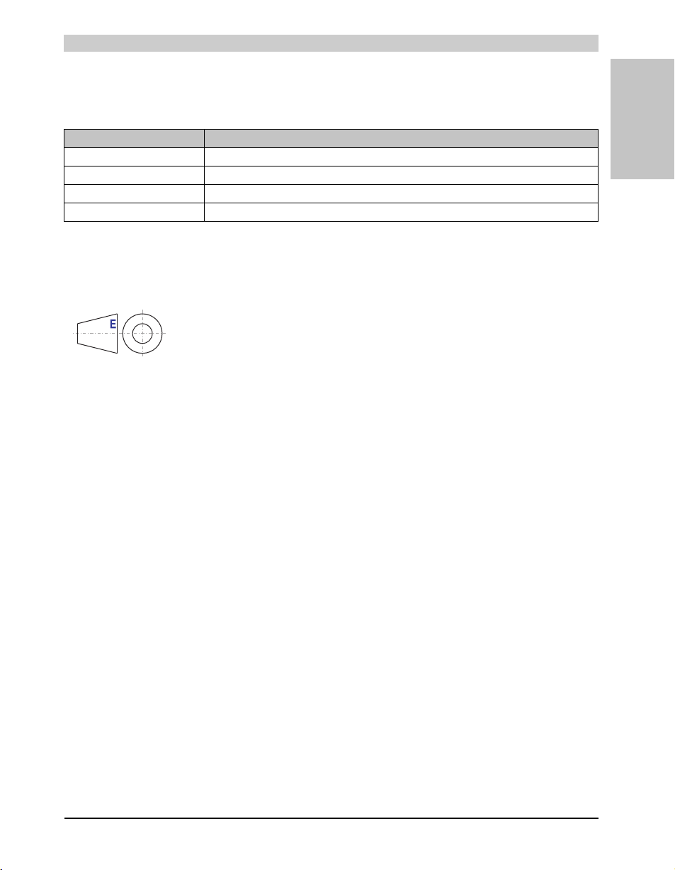
Danger! Disregarding the safety regulations and guidelines can be life-threatening.
Caution! Disregarding the safety regulations and guidelines can result in severe injury or major damage to material.
Warning! Disregarding the safety regulations and guidelines can result in injury or damage to material.
Information: Important information for preventing errors.
4. Directives
Section 1
General information
Table 3: Organization of safety notices
European dimension standards apply to all dimensions (e.g. dimension
diagrams, etc.).
23Panel PC 800 User's Manual V 1.00
Page 24
General information • Model numbers
5. Model numbers
5.1 System units
Model number Short description Note
5PC820.1505-00 PPC820 TFT C XGA 15in T
5PC820.1906-00 PPC820 TFT C SXGA 19in T
5.2 CPU boards 945GME COM Express
Model number Short description Note
5PC800.B945-00 CPU board Intel® Core™ Duo L2400, 1.66 GHz
5PC800.B945-10 CPU board Intel® Core™ Duo L2400, 1.66 GHz /2
5PC800.B945-01 CPU board Intel® Core™2 Duo L7400, 1.5 GHz
5PC800.B945-11 CPU board Intel® Core™2 Duo L7400, 1.5 /2
5PC800.B945-02 CPU board Intel® Core™2 Duo U7500, 1.06 GHz
5PC800.B945-12 CPU board Intel® Core™2 Duo U7500, 1.06 GHz /2
5PC800.B945-03 CPU board Intel® Celeron® M 423, 1.06 GHz
5PC800.B945-13 CPU board Intel® Celeron® M 423, 1.06 GHz /2
5PC800.B945-04 CPU board Intel® Core™2 Duo T7400, 2.16 GHz
5PC800.B945-14 CPU board Intel® Core™2 Duo T7400, 2.16 GHz /2
5PC800.B945-05 CPU board Intel® Atom™ N270, 1.6 GHz
Panel PC 820 15" TFT display with touch screen (resistive); connections for 1x RS232, 5x
USB 2.0, Smart Display Link/DVI/monitor, 2x Ethernet 10/100/1000, HDA sound, add-on UPS
slot, expandable with 1 or 2 PCI / PCI Express slots, optional PCI Express compact and slidein compact slot; IP65 protection (front side); 24 VDC. Plug for power supply must be ordered
separately (screw clamps: 0TB103.9; cage clamps: 0TB103.91).
Panel PC 820 19" SXGA color TFT display with touch screen (resistive); connections for 1x
RS232, 5x USB 2.0, Smart Display Link/DVI/monitor, 2x Ethernet 10/100/1000, HDA sound,
add-on UPS slot, expandable with 1 or 2 PCI / PCI Express slots, optional PCI Express
compact and slide-in compact slot; IP65 protection (front side); 24 VDC. Plug for power
supply must be ordered separately (screw clamps: 0TB103.9; cage clamps: 0TB103.91).
Table 4: Model numbers - system units
667 MHz FSB, 2 MB L2 cache; 945GME chipset; 2 sockets for SO-DIMM DDR2 module
667 MHz FSB, 2 MB L2 cache; 945GME chipset; 2 sockets for SO-DIMM DDR2 module
667 MHz FSB, 2 MB L2 cache; 945GME chipset; 4 sockets for SO-DIMM DDR2 module
667 MHz FSB, 2 MB L2 cache; 945GME chipset; 4 sockets for SO-DIMM DDR2 module
533 MHz FSB, 2 MB L2 cache; 945GME chipset; 2 sockets for SO-DIMM DDR2 module
533 MHz FSB, 2 MB L2 cache; 945GME chipset; 2 sockets for SO-DIMM DDR2 module
533 MHz FSB, 2 MB L2 cache; 945GME chipset; 1 sockets for SO-DIMM DDR2 module
533 MHz FSB, 2 MB L2 cache; 945GME chipset; 1 sockets for SO-DIMM DDR2 module
667 MHz FSB, 2 MB L2 cache; 945GME chipset; 4 sockets for SO-DIMM DDR2 module
667 MHz FSB, 2 MB L2 cache; 945GME chipset; 4 sockets for SO-DIMM DDR2 module
533 MHz FSB, 512 kB L2 Cache; Chipset 945GME; 2 sockets for SO-DIMM DDR2 module
Table 5: Model numbers - CPU boards 945GME
See page 66
See page 72
See page 78
See page 78
See page 78
See page 78
See page 78
See page 78
See page 78
See page 78
See page 78
See page 78
See page 78
24
Panel PC 800 User's Manual V 1.00
Page 25
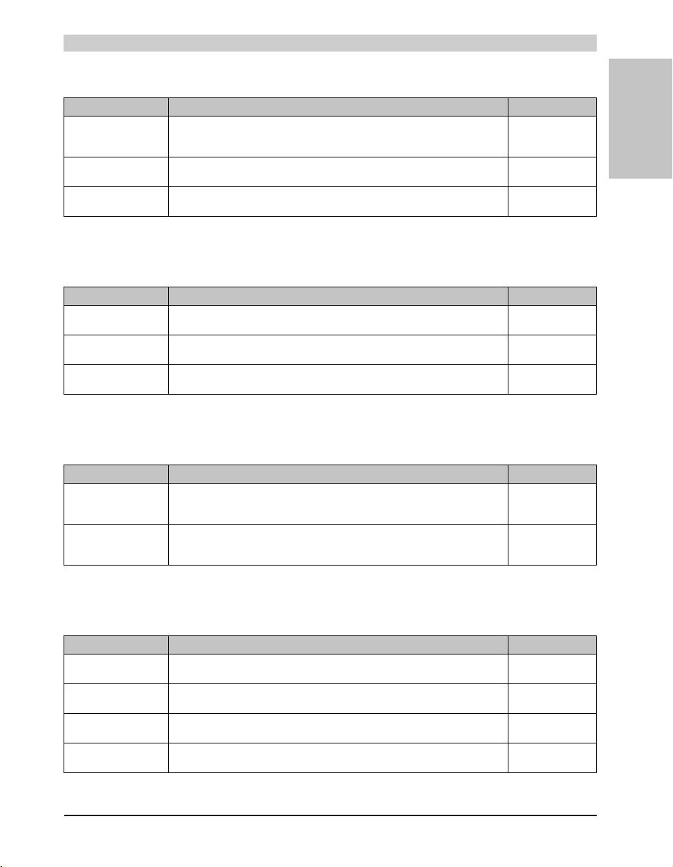
General information • Model numbers
5.3 Heat sink
Model number Short description Note
5AC803.HS00-00 Panel PC 800 heat sink
5AC803.HS00-01 Panel PC 800 heat sink T7400
5AC803.HS00-02 Panel PC 800 heat sink 945GME N270
PPC800 heat sink for CPU boards with Dual Core processors L2400, L7400, U7500 and
Celeron M 423.
PPC800 heat sink for CPU board with Dual Core processor T7400.
PPC800 heat sink for CPU boards with Atom N270 processor and Chipset 945GME.
See page 79
See page 79
See page 79
Table 6: Model numbers - Heat sinks
5.4 Main memory
Model number Short description Note
5MMDDR.0512-01 SO-DIMM DDR2 512MB PC2-5300
5MMDDR.1024-01 SO-DIMM DDR2 1024MB PC2-5300 See page 80
5MMDDR.2048-01 SO-DIMM DDR2 2048MB PC2-5300 See page 80
See page 80
Table 7: Model numbers - Main memory
5.5 Expansion
Section 1
General information
Model number Short description Note
5AC803.SX01-00 PPC800 Expansion 1CS 1SI
5AC803.SX02-00 PPC800 Expansion 2CS 1SI
PPC800 expansion 1 PCI/PCI Express and 1 slide-in (bus 5AC803.BX01-00 or
5AC803.BX01-01 required).
PPC800 expansion 2 PCI/PCI Express and 1 slide-in (bus 5AC803.BX02-00 or
5AC803.BX02-01 required).
See page 81
See page 81
Table 8: Model numbers - Expansion
5.6 Bus units
Model number Short description Note
5AC803.BX01-00 PPC800 bus 1PCI 1SI
5AC803.BX01-01 PPC800 bus 1PCIe.x1 1SI
5AC803.BX02-00 PPC800 bus 2PCI 1SI
5AC803.BX02-01 PPC800 bus 1PCI 1PCIe.x1 1SI
PPC800 bus 1 PCI, 1 slide-in slot.
PPC800 bus 1 PCI Express, 1 slide-in slot.
PPPC800 bus 2 PCI, 1 slide-in slot.
PPC800 bus 1 PCI, 1 PCI Express, 1 slide-in slot.
Table 9: Model numbers - bus units
See page 86
See page 86
See page 86
See page 86
25Panel PC 800 User's Manual V 1.00
Page 26
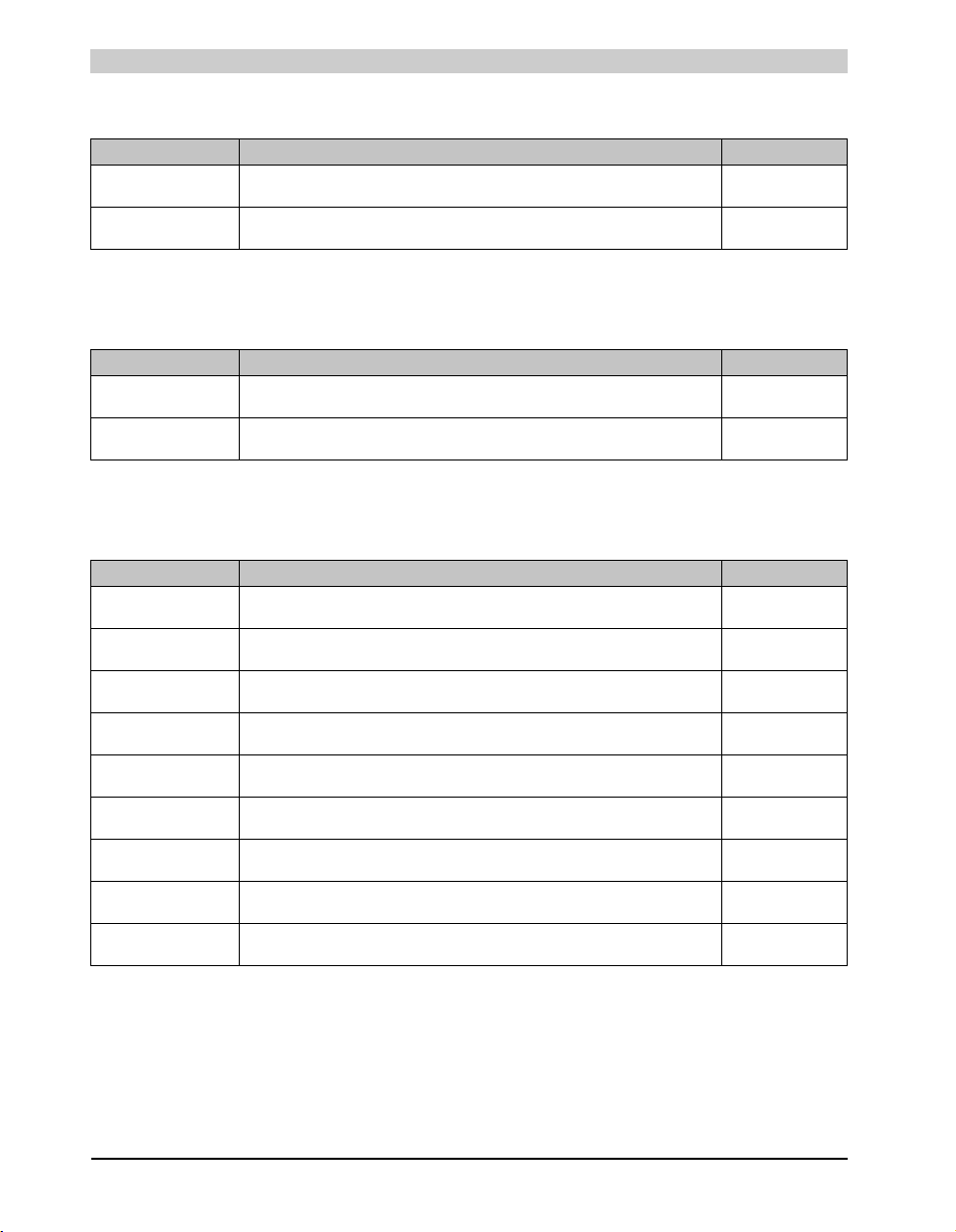
General information • Model numbers
5.7 Option
Model number Short description Note
5AC803.BC01-00 PPC800 option PCI Express compact
PPC800 option for expanding a PCIec card in the system unit.
5AC803.BC02-00 PPC800 option slide-in compact
PPC800 option for expanding a slide-in compact drive in the system unit.
See page 88
See page 88
Table 10: Model numbers - Option
5.8 Plug-in cards
Model number Short description Note
5ACPCC.ETH0-00 PCIec Ethernet card 10/100/1000
PCIec Ethernet plug-in card, 1 Ethernet interface 10/100/1000
5ACPCC.MPL0-00 PCIec POWERLINK MN 2-port
PCIec POWERLINK plug-in card, 2 POWERLINK interfaces
See page 90
See page 92
Table 11: Model numbers - Drives
5.9 Drives
Model number Short description Note
5AC801.ADAS-00 APC810 slide-in compact adapter
5AC801.HDDI-00 APC810 slide-in compact HDD 40GB
5AC801.HDDI-02 APC810 slide-in compact HDD 160GB 24x7 ET
5AC801.HDDS-00 APC810 slide-in HDD 40GB
5AC801.SSDI-00 APC8 10 slide-in compact HDD 32GB (SLC)
5AC801.DVDS-00 APC810 slide-in DVD-ROM
5AC801.DVRS-00 APC810 slide-in DVD-R/RW
5ACPCI.RAIC-03 PCI SATA RAID System 2x160 GB
5ACPCI.RAIC-04 Replacement SATA-HDD 160GB
Adapter for operating compact slide-in drives in a slide-in slot drive slot.
40 GB SATA hard disk (slide-in compact), 24/7 hard disk with extended temperature range.
160 GB SATA hard disk (slide-in compact), 24/7 hard disk with extended temperature range.
40 GB SATA hard disk (slide-in), 24/7 hard disk with extended temperature range.
32 GB SSD drive (slide-in)
DVD-ROM drive (slide-in)
DVD-R/RW, DVD+R/RW drive (slide-in)
PCI RAID controller + 2 x 160 GB SATA hard disks; requires a free PCI slot.
Hard disk 160 GB SATA, replacement part for 5ACPCI.RAIC-03
Table 12: Model numbers - Drives
See page 105
See page 95
See page 98
See page 106
See page 101
See page 109
See page 112
See page 116
See page 121
26
Panel PC 800 User's Manual V 1.00
Page 27
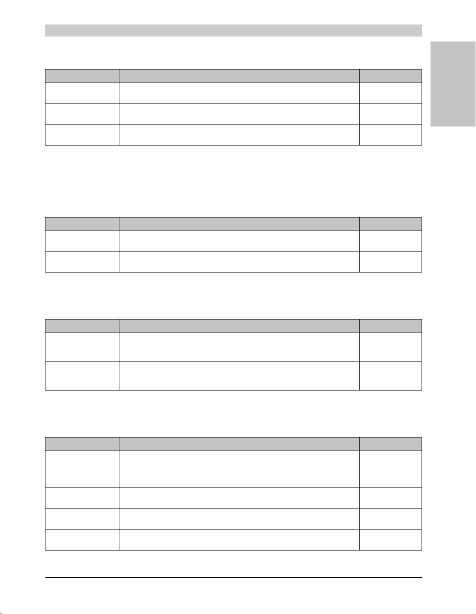
General information • Model numbers
5.10 Fan kits
Model number Short description Note
5AC803.FA01-00 PPC800 fan kit 1CS
APC800 fan kit for system units without an expansion.
5AC803.FA02-00 PPC800 fan kit 2CS
APC800 fan kit for system units with expansion 5AC803.SX01-00.
5AC803.FA03-00 PPC800 fan kit 3CS
APC800 fan kit for system units with expansion 5AC803.SX02-00.
See page 124
See page 125
See page 126
Table 13: Model numbers - Fan kits
5.11 Accessories
5.11.1 Batteries
Model number Short description Note
0AC201.91 Lithiu m batteries, 4 pcs.
4A0006.00-000 Lithium battery, 1 pc.
Lithium batteries, 4 pcs., 3 V / 950 mAh, button cell
Lithium battery, 1 pc., 3 V / 950 mAh, button cell
Table 14: Model numbers - Batteries
5.11.2 Supply voltage connectors
See page 294
See page 294
Section 1
General information
Model number Short description Note
0TB103.9 Plug 24V 5.08 3-pin screw clamps
0TB103.91 Plug 24V 5.08 3-pin cage clamps
24 VDC 3-pin connector, female. Screw clamp, 3.31 mm², protected against vibration by the
screw flange.
24 VDC 3-pin connector, female. Cage clamps, 3.31 mm², protected against vibration by the
screw flange.
See page 296
See page 296
Table 15: Model numbers - Supply voltage connectors
5.11.3 UPS module + accessories
Model number Short description Note
5AC600.UPSI-00 Add-on UPS module
5AC600.UPSB-00 Battery unit 5 Ah
5CAUPS.0005-00 0.5 m APC620 UPS cable
5CAUPS.0030-00 3 m APC620 UPS cable
UPS module for APC620 / APC810 / PPC800 system units.
Order cable (5CAUPS.0005-00 or 5CAUPS.0030-00) and battery unit (5AC600.UPSB-00)
separately.
UPS battery unit for the add-on UPS module
Connection cable between add-on UPS module and UPS battery unit, length 0.5 meters
Connection cable between add-on UPS module and UPS battery unit, length 3 meters
Table 16: Model numbers - UPS module + accessories
See page 300
See page 300
See page 300
See page 300
27Panel PC 800 User's Manual V 1.00
Page 28
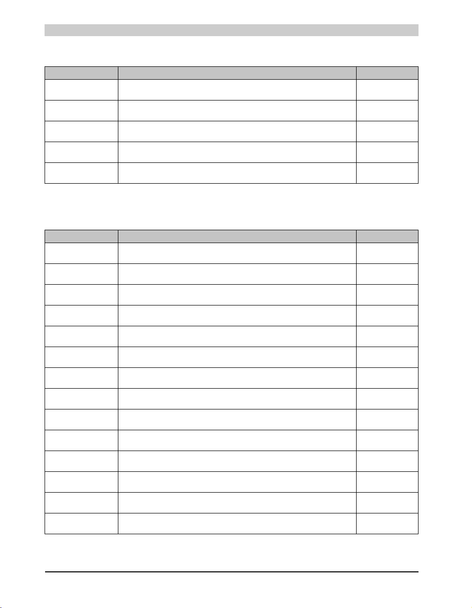
General information • Model numbers
5.11.4 External UPS
Model number Short description Note
9A0100.11 UPS 24 VDC
9A0100.14 UPS battery unit type B
9A0100.15 UPS battery unit type B (replacement part)
9A0017.01 RS232 Null Modem Cable, 0.6 m
9A0017.02 RS232 Null Modem Cable, 1.8 m
24 VDC input, 24 VDC output, serial interface
24 V; 2.2 Ah; including battery cage
2 x 12 V; 2.2 Ah; for battery unit 9A0100.14
To connect UPS and load system (9-pin DSUB socket - 9-pin DSUB socket)
To connect UPS and load system (9-pin DSUB socket - 9-pin DSUB socket)
See page 309
See page 309
See page 309
See page 309
See page 309
Table 17: Model numbers - External UPS
5.11.5 CompactFlash cards
Model number Short description Note
5CFCRD.0512-04 CompactFlash 512 MB B&R
5CFCRD.1024-04 CompactFlash 1024 MB B&R
5CFCRD.2048-04 CompactFlash 2048 MB B&R
5CFCRD.4096-04 CompactFlash 4096 MB B&R
5CFCRD.8192-04 CompactFlash 8192 MB B&R
5CFCRD.016G-04 16 GB B&R CompactFlash card
5CFCRD.0064-03 CompactFlash 64 MB SSI
5CFCRD.0128-03 CompactFlash 128 MB SSI
5CFCRD.0256-03 CompactFlash 256 MB SSI
5CFCRD.0512-03 CompactFlash 512 MB SSI
5CFCRD.1024-03 CompactFlash 1024 MB SSI
5CFCRD.2048-03 CompactFlash 2048 MB SSI
5CFCRD.4096-03 CompactFlash 4096 MB SSI
5CFCRD.8192-03 CompactFlash 8192 MB SSI
CompactFlash card with 512 MB SLC NAND flash and IDE/ATA interface
CompactFlash card with 1024 MB SLC NAND flash and IDE/ATA interface
CompactFlash card with 2048 MB SLC NAND flash and IDE/ATA interface
CompactFlash card with 4096 MB SLC NAND flash and IDE/ATA interface
CompactFlash card with 8192 MB SLC NAND flash and IDE/ATA interface
CompactFlash card with 16 GB SLC NAND flash and IDE/ATA interface
CompactFlash card with 64 MB SLC NAND flash and IDE/ATA interface
CompactFlash card with 128 MB SLC NAND flash and IDE/ATA interface
CompactFlash card with 256 MB SLC NAND flash and IDE/ATA interface
CompactFlash card with 512 MB SLC NAND flash and IDE/ATA interface
CompactFlash card with 1024 MB SLC NAND flash and IDE/ATA interface
CompactFlash card with 2048 MB SLC NAND flash and IDE/ATA interface
CompactFlash card with 4096 MB SLC NAND flash and IDE/ATA interface
CompactFlash card with 8192 MB SLC NAND flash and IDE/ATA interface
Table 18: Model numbers - CompactFlash cards
See page 311
See page 311
See page 311
See page 311
See page 311
See page 311
See page 316
See page 316
See page 316
See page 316
See page 316
See page 316
See page 316
See page 316
28
Panel PC 800 User's Manual V 1.00
Page 29
General information • Model numbers
5.11.6 USB flash drives
Model number Short description Note
5MMUSB.2048-00 USB flash drive 2 GB SanDisk
USB 2.0 flash drive 2 GB
See page 320
Table 19: Model numbers - USB flash drives
5.11.7 Cables
Model number Short description Note
5CADVI.0018-00 DVI-D cable 1.8 m
5CADVI.0050-00 DVI-D cable 5 m
5CADVI.0100-00 DVI-D cable 10 m
5CASDL.0018-00 SDL cable 1.8 m
5CASDL.0018-01 SDL cable 1.8 m 45°
5CASDL.0018-03 SDL flex cable 1.8 m
5CASDL.0050-00 SDL cable 5 m
5CASDL.0050-01 SDL cable 5 m 45°
5CASDL.0050-03 5 m flex SDL cable
5CASDL.0100-00 SDL cable 10 m
5CASDL.0100-01 SDL cable 10 m 45°
5CASDL.0100-03 10 m flex SDL cable
5CASDL.0150-00 SDL cable 15 m
5CASDL.0150-01 SDL cable 15 m 45°
5CASDL.0150-03 15 m flex SDL cable
5CASDL.0200-00 SDL cable 20 m
5CASDL.0200-03 20 m flex SDL cable
5CASDL.0250-00 SDL cable 25 m
Single cable, DVI-D/m:DVI-D/m; length: 1.8 m
Single cable, DVI-D/m:DVI-D/m; length: 5 m
Single cable, DVI-D/m:DVI-D/m; length: 10 m
SDL cable for a fixed type of layout; length: 1.8 m
SDL cable for fixed type of layout with one-sided 45° plug; length: 1.8 m
SDL cable for fixed and flexible type of layout; length: 1.8 m
SDL cable for a fixed type of layout; length: 5 m
SDL cable for fixed type of layout with one-sided 45° plug; length: 5 m
SDL cable for fixed and flexible type of layout; length: 5 m
SDL cable for a fixed type of layout; length: 10 m
SDL cable for fixed type of layout with one-sided 45° plug; length: 10 m
SDL cable for fixed and flexible type of layout; length: 10 m
SDL cable for a fixed type of layout; length: 15 m
SDL cable for fixed type of layout with one-sided 45° plug; length: 15 m
SDL cable for fixed and flexible type of layout; length: 15 m
SDL cable for a fixed type of layout; length: 20 m
SDL cable for fixed and flexible type of layout; length: 20 m
SDL cable for a fixed type of layout; length: 25 m
Table 20: Model numbers - Cables
See page 327
See page 327
See page 327
See page 330
See page 333
See page 336
See page 330
See page 333
See page 336
See page 330
See page 333
See page 336
See page 330
See page 333
See page 336
See page 330
See page 336
See page 330
Section 1
General information
29Panel PC 800 User's Manual V 1.00
Page 30
General information • Model numbers
Model number Short description Note
5CASDL.0250-03 25 m flex SDL cable
5CASDL.0300-00 SDL cable 30 m
5CASDL.0300-03 30 m flex SDL cable
5CASDL.0300-13 30 m SDL flex cable with extender
5CASDL.0400-13 40 m SDL flex cable with extender
5CAUSB.0018-00 USB 2.0 cable, A/m:B/m 1.8 m
5CAUSB.0050-00 USB 2.0 cable, A/m:B/m 5 m
9A0014.02 RS232 cable DB9/f:DB9/m 1.8 m
9A0014.05 RS232 cable DB9/f:DB9/m 5 m
9A0014.10 RS232 cable DB9/f:DB9/m 10 m
SDL cable for fixed and flexible type of layout; length: 25 m
SDL cable for a fixed type of layout; length: 30 m
SDL cable for fixed and flexible type of layout; length: 30 m
SDL cable with extender for fixed and flexible type of layout; length: 30 m
SDL cable with extender for fixed and flexible type of layout; length: 40 m
USB 2.0 connection cable; plug type A - type B; length 1.8 m
USB 2.0 connection cable; plug type A - type B; length 5 m
RS232 extension cable for remote operation of a display unit with touch screen; length 1.8 m.
RS232 extension cable for remote operation of a display unit with touch screen; length 5 m.
RS232 extension cable for remote operation of a display unit with touch screen; length 10 m.
See page 336
See page 330
See page 336
See page 341
See page 341
See page 348
See page 348
See page 346
See page 346
See page 346
Table 20: Model numbers - Cables (cont.)
5.11.8 Miscellaneous
Model number Short description Note
5AC900.1000-00 Adapter DVI-A/m to CRT DB15HD/f
5AC900.1200-01 USB port cap IP65 M20 /2
5AC900.1200-02 USB port cap IP65 M20 /3
5AC900.1200-03 USB port cap IP65 M20 /4
1A4300.LZ1U B&R Automation Studio 3.0 USB dongle
Adapter DVI (plug) to CRT (socket), for connecting a standard monitor to a DVI-I interface.
Front-side USB port cap (attached) knurled, short, not slotted.
Front-side USB port cap (attached) knurled, tall, not slotted.
Front-side USB port cap (attached) knurled, tall, slotted.
Dongle for using AR010.
See page 298
See page 299
See page 299
See page 299
See page 323
Table 21: Model numbers - Other items
30
Panel PC 800 User's Manual V 1.00
Page 31
General information • Model numbers
5.12 Software
Model number Short description Note
5SWHMI.0000-00 HMI Drivers & Utilities DVD
9S0000.01-010 OEM MS-DOS 6.22 German (disk)
9S0000.01-020 OEM MS-DOS 6.22 English (disk)
5SWWXP.0600-GER WinXP Professional with SP3, GER
5SWWXP.0600-ENG WinXP Professional with SP3, ENG
5SWWXP.0600-MUL WinXP Professional with SP3, MUL
5SWWXP.0500-GER WinXP Professional with SP 2c, GER
5SWWXP.0500-ENG WinXP Professional with SP 2c, ENG
5SWWXP.0500-MUL WinXP Professional with SP 2c, MUL
5SWWXP.0427-ENG WinXPe FP2007 PPC800 945GME
5SWWXP.0727-ENG Windows Embedded Standard 2009 PPC800 945GME
Contains drivers, utilities, software upgrades and user's manuals for B&R panel system
products (see B&R homepage – Industrial PCs, Visualization and Operation).
OEM MS-DOS 6.22 German disks
Only delivered with a new industrial PC.
OEM MS-DOS 6.22 English disks
Only delivered with a new industrial PC.
Microsoft OEM Windows XP Professional Service Pack 3, CD, German. Only available with
a new device.
Microsoft OEM Windows XP Professional Service Pack 3, CD, English. Only available with a
new device.
Microsoft OEM Windows XP Professional Service Pack 3, CD, multi-language. Only available
with a new device.
Microsoft OEM Windows XP Professional Service Pack 2c, CD, German. Only available with
a new device.
Microsoft OEM Windows XP Professional Service Pack 2c, CD, English. Only available with
a new device.
Microsoft OEM Windows XP Professional Service Pack 2c, CD, multi-language. Only
available with a new device.
Order Microsoft OEM Windows XP embedded Feature Pack 2007, English; for PPC800 with
CPU boards 5PC800.B945-00, 5PC800.B945-01, 5PC800.B945-02, 5PC800.B945-03,
5PC800.B945-04; 5PC800.B945-05; CompactFlash separately (at least 512 MB).
Order Microsoft OEM Windows Embedded Standard 2009, English; for PPC800 with CPU
boards 5PC800.B945-00, 5PC800.B945-01, 5PC800.B945-02, 5PC800.B945-03,
5PC800.B945-04, 5PC800.B945-05; CompactFlash separately (at least 1 GB).
Table 22: Model numbers - Software
See page
See page 247
See page 247
See page 249
See page 249
See page 249
See page 249
See page 249
See page 249
See page 250
See page 253
Section 1
General information
31Panel PC 800 User's Manual V 1.00
Page 32

General information • Model numbers
32
Panel PC 800 User's Manual V 1.00
Page 33
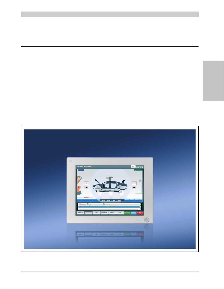
Technical data • Introduction
Chapter 2 • Technical data
1. Introduction
The Panel PC 800 covers a wide performance range from efficient Intel Atom N270 processors
to Core2 Duo processors for applications with the highest performance requirements. Brilliant
15" XGA and 19" SXGA touch screen displays provide a simple and intuitive user interface. The
flexibility was raised to a new level when designing the PPC800. Therefore, many options can
be implemented on the cost-optimized basic device. This includes up to two PCI and PCI
Express slots, modular drives, additional interfaces and an integrated UPS. The chipset,
processor and other components are connected directly to the heat sink using heat conductive
materials. This makes it possible to operate Atom processors without a fan, and also select dual
core processors.
Section 2
Technical data
33Panel PC 800 User's Manual V 1.00
Page 34

Technical data • Introduction
1.1 Features
• 15" and 19" diagonals
• Latest processor technologies - Core Duo, Core 2 Duo, Celeron M and Atom N270
• Up to 3 GB main memory (Dual Channel Memory Support)
• 2 CompactFlash slots (type I)
• Expandable expansion with 1 or 2 slots for PCI / PCI Express (PCIe) cards and a slidein drive slot
• 1 optional PCIec (PCI express compact) card slot (can be expanded with option)
• 1 optional slide-in compact slot (can be expanded with option)
• 5x USB 2.0
• 2x Ethernet 10/100/1000 MBit interfaces
• 1x RS232 interface, modem compatible
• 24 VDC supply voltage
•BIOS (AMI)
• Real-time clock, RTC (battery-buffered)
• Easy slide-in drive exchange (SATA hot plug capable)
• HDA Sound
• Add-on UPS slot
34
Panel PC 800 User's Manual V 1.00
Page 35
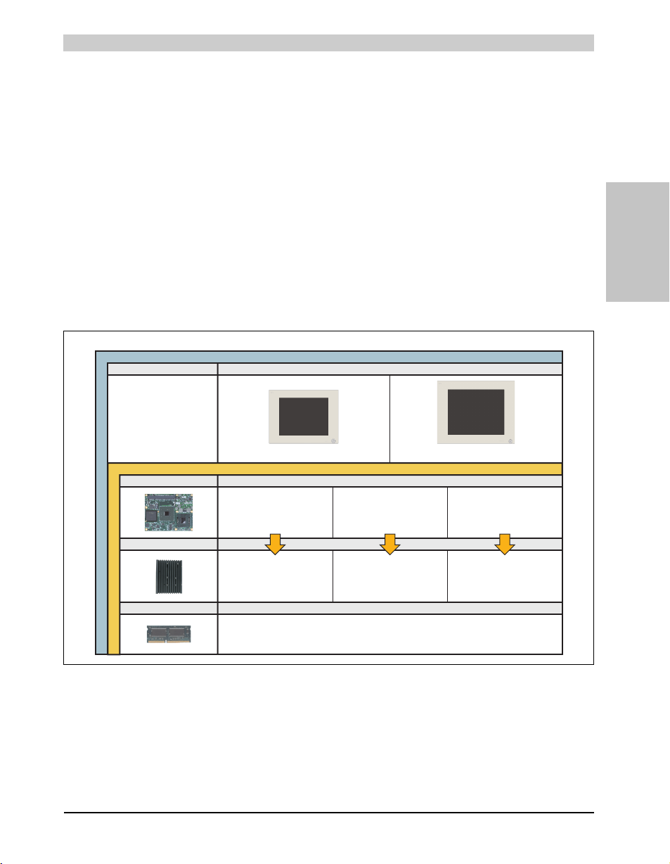
Technical data • Introduction
5AC803.HS00-02
5PC800.B945-05
CPU board
5AC803.HS00-01
1 or 2 can be selected (max. 3 GB can be used)
Select 1
Select 1
5PC800.B945-00 / -10
5PC800.B945-01 / -11
5PC800.B945-02 / -12
5PC800.B945-03 / -13
5AC803.HS00-00
System unit
Configuration - Base system
5MMDDR.0512-01 - 512 MB
5MMDDR.1024-01 - 1 GB
5MMDDR.2048-01 - 2 GB
CPU board - Heat sink - Main memory
Select 1
Main memory
Heat sink
5PC800.B945-04 / -14
5PC820.1505-00 5PC820.1906-00
1.2 System components / Configuration
The PPC800 system can be assembled to meet individual requirements and operating
conditions.
The following components are absolutely essential for operation:
• System unit
• CPU board
• Heat sink (CPU board dependent)
• Main memory
• Drive (mass memory such as CompactFlash card or hard disk) for the operating system
• Software
1.2.1 Configuration - Basic system
Section 2
Technical data
Figure 1: Configuration - Basic system
35Panel PC 800 User's Manual V 1.00
Page 36
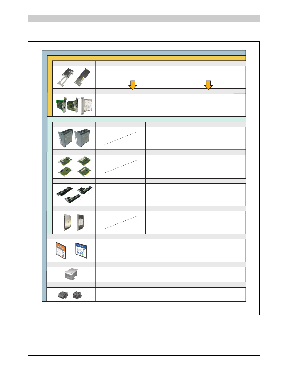
Technical data • Introduction
Configuration of a system unit with option
Configuration of a system unit with expansion
Configuration - Optional components
5AC801.HDDI-00 (40 GB)
5AC801.HDDI-02 (160 GB)
5AC801.SSDI-00 (32 GB)
Fan kit
5AC803.FA01-00 5AC803.FA02-00 5AC803.FA03-00
Slide-in compact drives, select 1
Select 1
UPS battery
Select 1
Supply voltage connector
0TB103.9 (screw clamp)
0TB103.91 (cage clamp)
CompactFlash Select 1 or 2
5CFCRD.0512-04, 5CFCRD.1024-04,
5CFCRD.2048-04, 5CFCRD.4096-04,
5CFCRD.8192-04, 5CFCRD.016G-04
5AC600.UPSI-00 (add-on UPS module), 5AC600.UPSB-00 (UPS battery unit)
onnection cable -> Battery: 5CAUPS.0005-00 (0.5 meter) or 5CAUPS.0030-00 (3 meters)APC c
5CFCRD.0064-03, 5CFCRD.0128-03,
5CFCRD.0256-03, 5CFCRD.0512-03,
5CFCRD.1024-03, 5CFCRD.2048-03,
5CFCRD.4096-03, 5CFCRD.8192-03
5AC803.BX02-00
5AC803.BX02-01
Expansion 1 PCI/PCIe slot + 1 slide-in slot
Select 1
5AC803.SX01-00
Bus units Select 1
5AC803.BX01-00
5AC803.BX01-01
5AC803.SX02-00
5AC803.BC01-00
Select 1 or both
5ACPCC.ETH0-00 (PCIec Ethernet Card 10/100/1000)
5ACPCC.MPL0-00 (PCIec POWERLINK MN 2-port)
1PCIec plug-in cards, select
2)
1)2)If both options are used, then a PCIec plug-in card and a slide-in compact drive can also be operated in a device.
A fan kit may be necessary for certain system configurations.
5AC803.BC02-00
Option
1)
No expansion
Slide-in drives
5AC801.HDDS-00 (40 GB)
5AC801.DVRS-00 (DVD burner)
5
5AC801.DVDS-00 (DVD drive)
AC801.ADAS-00 (adapter)
Select 1
2 PCI/PCIe slots + 1 slide-in slot
Select 1
Select 1 Select 1
1.2.2 Configuration - Optional components
36
Figure 2: Configuration - Optional components
Panel PC 800 User's Manual V 1.00
Page 37

Technical data • Entire device
2. Entire device
2.1 Temperature specifications
It is possible to combine CPU boards with various other components, such as drives, main
memory, additional insert cards, etc. depending on system unit and fan kit. The various
configurations result in varying maximum possible ambient temperatures, which can be seen in
the following graphics.
Information:
The maximum specified ambient temperatures for operation with and without a fan
kit were determined under worst-case conditions. Experience has shown that higher
ambient temperatures can be reached under typical conditions, e.g. using Microsoft
Windows. The testing and evaluation is to be done on-site by the user (temperatures
can be read in BIOS or using the B&R Control Center).
Information on the worst-case conditions
• Thermal Analysis Tool (TAT V3.8) from Intel for simulating 100% processor load
• BurnIn testing tool (BurnIn V4.0 Pro from Passmark Software) to simulate a 100% load
on the interface via loop-back adapters (serial interfaces, slide-in drives, USB interfaces,
audio outputs)
• Maximum system extension and power consumption
What must be considered when determining the maximum ambient temperature?
• Operating the entire device with or without fan kit
Section 2
Technical data
37Panel PC 800 User's Manual V 1.00
Page 38
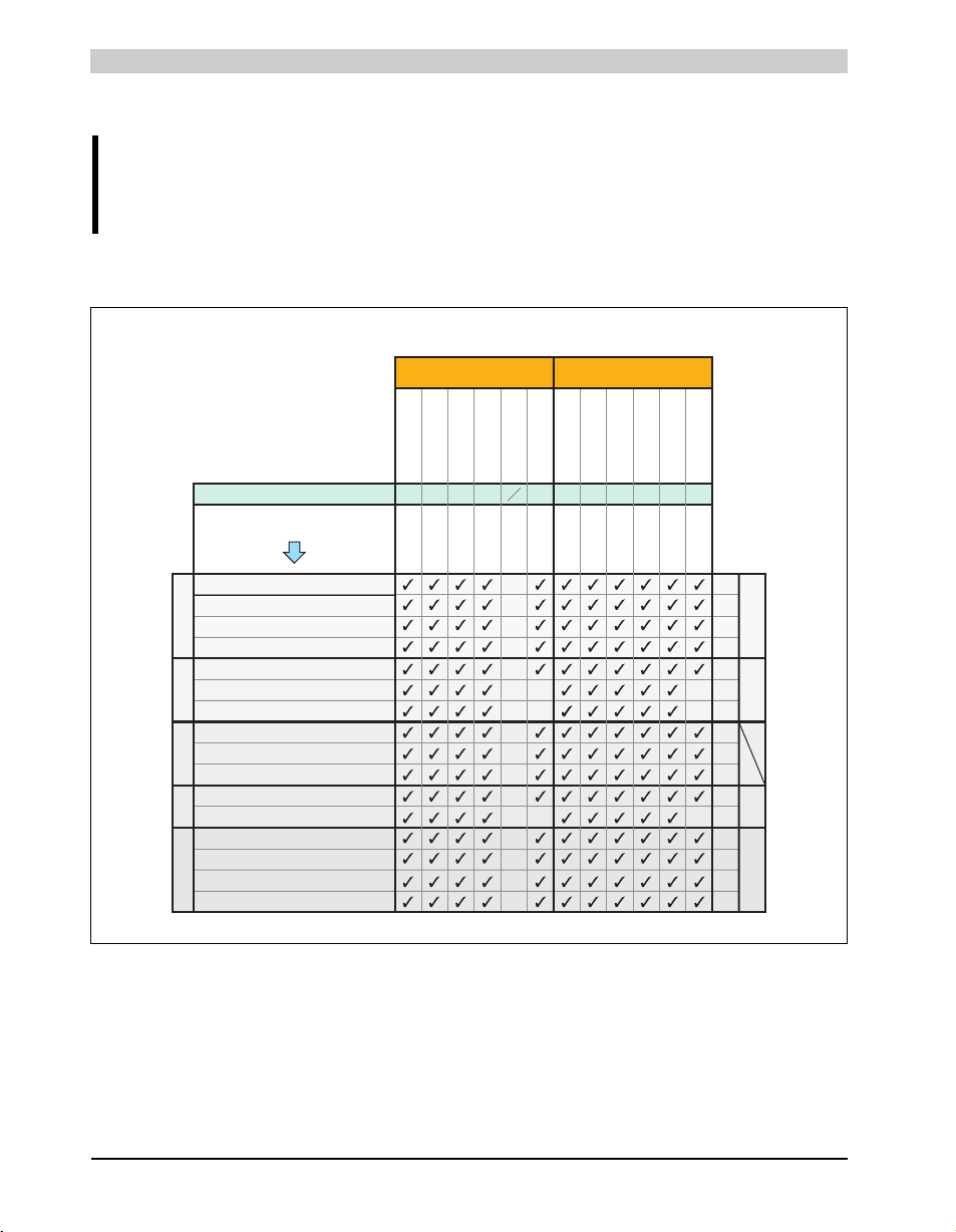
Technical data • Entire device
-
-
-
-
-
80
80
80
80
80
80
50
50
70
50
50
-
-
50
50
45 50
Operation with fan kit
On-board CompactFlash
5AC801.HDDI-00
5AC801.DVDS-00
5AC801.DVRS-00
Slide-in option
Main memory
5MMDDR.0512-01
5MMDDR.1024-01
5MMDDR.2048-01
System
units
5PC820.1505-00
5PC820.1906-00
5ACPCC.ETH0-00
5ACPCC.MPL0-00
Maximum ambient temperature
1) Only possible with a CompactFlash card ( .5CFCRD.xxxx-04 or 5CFCRD.xxxx-03) from B&R
5AC801.HDDS-00
Additional insert cards
PCIec card slot
Board power
Slide-in
drive
Power
Supply
All temperature values in degrees
celsius (°C) at 500 meters above sea level.
Derating of the maximum ambient
temperature generally 1°C per 1000 meters
starting at 500 meters above sea level.
30 35 45 45 50 50
Slide-in Compact
5AC801.HDDI-02
30
35 35
Location of sensor(s)
1)
5AC801.HDDI-02
5AC801.SSDI-00
What can also be operated at the max. ambient
temperature, or are there limits?
5PC800.B945-02
5PC800.B945-03
U7500 CM 423
5PC800.B945-00
L2400
5PC800.B945-01
L7400
Temperature limits
5PC800.B945-02
5PC800.B945-03
U7500 CM 423
5PC800.B945-00
L2400
5PC800.B945-01
L7400
5PC800.B945-04
T7400
5PC800.B945-04
T7400
Additional
insert cards
Operation without fan kit
55
5PC800.B945-05
N270
60
5PC800.B945-05
N270
ETH1: up to 1 GBit operation
ETH2: up to 1 GBit operation
ETH1: up to 1 GBit operation
ETH2: up to 1 GBit operation
5ACPCI.RAIC-03 (24 hours / default)
5ACPCI.RAIC-04 (24 hours / default)
2.1.1 Maximum ambient temperature
Information:
Only specified mounting orientations are permitted. See chapter 3
"Commissioning", section 1.2 "Mounting orientation", on page 129.
Ambient temperature for CPU boards 5PC800.B945-0x
Figure 3: Ambient temperatures with and without fan kit - CPU boards 5PC800.B945-0x
38
Panel PC 800 User's Manual V 1.00
Page 39
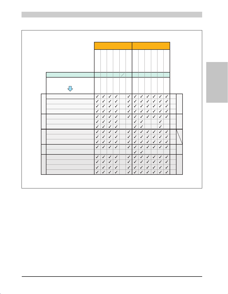
Technical data • Entire device
-
-
-
-
-
-
-
80
80
80
80
80
80
50
50
70
30 35 3530 50 50 35
50
50
50
50
505050
50
5ACPCI.RAIC-03 (24 hours / default)
5ACPCI.RAIC-04 (24 hours / default)
Operation with fan kit
On-board CompactFlash
5AC801.HDDI-00
5AC801.DVDS-00
5AC801.DVRS-00
Slide-in option
Main memory
5MMDDR.0512-01
5MMDDR.1024-01
5MMDDR.2048-01
System
units
5PC820.1505-00
5PC820.1906-00
5ACPCC.ETH0-00
5ACPCC.MPL0-00
Maxim um ambient temperature
1) The specified temperature is only valid for the CPU board 5PC800.B945-14 with the heat sink 5AC803.HS00-01 Rev > A5.
If a heat sink with an earlier revision is used, then the maximum ambient temperature of the CPU board 5PC800.B954-04 must be referred to.
2) Only possible with a CompactFlash card ( .5CFCRD.xxxx-04 or 5CFCRD.xxxx-03) from B&R
5AC801.HDDS-00
Additional insert cards
PCIec card slot
Board power
Slide-in
drive
Power
Supply
All temperature values in degrees
celsius (°C) at 500 meters above sea level.
Derating of the maximum ambient
temperature, generally 1°C per 1000 meters
starting at 500 meters above sea level.
35 45 45 45 55 55
Slide-in Compact
5AC801.HDDI-02
35
45 45
Location of sensor(s)
2)
5AC801.HDDI-02
5AC801.SSDI-00
What can also be operated at the max. ambient
temperature, or are there limits?
5PC800.B945-12
5PC800.B945-13
U7500 CM 423
5PC800.B945-10
L2400
5PC800.B945-11
L7400
Temperature limits
5PC800.B945-12
5PC800.B945-13
U7500 CM 423
5PC800.B945-10
L2400
5PC800.B945-11
L7400
5PC800.B945-14
T7400
5PC800.B945-14
T7400
Additional
insert cards
Operation without fan kit
55
5PC800.B945-05
N270
60
5PC800.B945-05
N270
ETH1: up to 1 Gbit
ETH2: 1 GBit
operation
up to operation
ETH1: 1 Gbit
ETH2: 1 GBit operation
up to operation
up to
1)
5045
Ambient temperature for CPU boards 5PC800.B945-1x and 5PC800.B945-05
Section 2
Technical data
Figure 4: Ambient temperatures with and without fan kit - CPU boards 5PC800.B945-1x and 5PC800.B945-
05
2.1.2 Minimum ambient temperature
For systems containing one of the following components, the minimum ambient temperature is
+5°C: 5AC801.DVDS-00, 5AC801.DVRS-00. If none of these components are used, then the
minimum ambient temperature is 0°C.
39Panel PC 800 User's Manual V 1.00
Page 40

Technical data • Entire device
2.1.3 How do you determine the maximum ambient temperature?
1) Selection of the CPU board (use with or without fan kit).
2) The "maximum ambient temperature" line shows the maximum ambient temperature for the
entire system when using the respective CPU board.
Information:
Maximum temperature data is for operation at 500 meters. Derating the maximum
ambient temperature - typically 1°C per 1000 meters (from 500 meters above sea
level).
3) Incorporating additional drives (slide-in), main memory, additional insert cards, etc. can
change the temperature limits of an PPC800 system.
If there is a ✓ (checkmark) next to the component, it can be used at the maximum ambient
temperature of the whole system without problems.
If there is a specific temperature, for example "50", next to the component, then the ambient
temperature of the whole PPC800 system cannot exceed this temperature.
2.1.4 Temperature monitoring
Sensors monitor temperature values in various places (board I/O, board ETH2, board power,
power supply, slide-in drive 1, IF slot) in the PPC800. The position of the temperature sensors
can be found in the figure "Temperature sensor locations", on page 353. The value listed in the
table represents the defined maximum temperature for this measurement point
triggered when this temperature is exceeded. The temperatures
1)
can be read in BIOS (menu
item "Advanced" - Baseboard/panel features - Baseboard monitor) or in Microsoft Windows
XP/Embedded and Windows Embedded Standard 9000 using the B&R Control Center.
Additionally, the hard disks for PPC800 systems available from B&R are equipped with
S.M.A.R.T, or Self Monitoring, Analysis, and Reporting Technology. This makes it possible to
read various parameters, for example the temperature, using software (e.g. HDD thermometer freeware) in Microsoft Windows XP/Embedded and Windows Embedded Standard 2009.
1)
. An alarm is not
1) The measured temperature is a guideline for the immediate ambient temperature, but can be influenced by neighboring components.
40
Panel PC 800 User's Manual V 1.00
Page 41
Technical data • Entire device
2.2 Humidity specifications
The following table displays the minimum and maximum humidity for the individual components
that are relevant for the humidity limitations of the entire device. The lowest and highest common
values are always used when establishing these limits.
Component Operation Storage / Transport
CPU boards 945GME COM Express 10 - 90% 5 - 95%
Main memory for CPU boards 10 - 90% 5 - 95%
5AC801.HDDI-00 5 - 90% 5 - 95%
5AC801.HDDI-02 8 - 80% 5 - 95%
Slide-in compact drives
Slide-in drives
Additional insert cards
Accessories
Table 23: Overview of humidity specifications for individual components
5AC801.SSDI-00 5 - 95% 5 - 95%
5AC801.HDDS-00 5 - 90% 5 - 90%
5AC801.DVDS-00 8 - 90% 5 - 95%
5AC801.DVRS-00 8 - 90% 5 - 95%
5ACPCI.RAIC-03 (24 hours/default) 8 - 90% 5 - 95%
5ACPCI.RAIC-04 (24 hours/default) 8 - 90% 5 - 95%
CompactFlash cards 5CFCRD.xxxx-04 85% 85%
CompactFlash cards - 5CFCRD.xxxx-03 8 - 95% 8 - 95%
Flash drive 5MMUSB.2048-00 10 - 90% 5 - 90%
USB Media Drive 5MD900.USB2-01 20 - 80% 5 - 90%
Section 2
Technical data
The listed specifications correspond to the humidity at an ambient temperature of 30°C. More
detailed information about the specific temperature-dependent humidity values can be found in
the technical data for the individual components.
41Panel PC 800 User's Manual V 1.00
Page 42
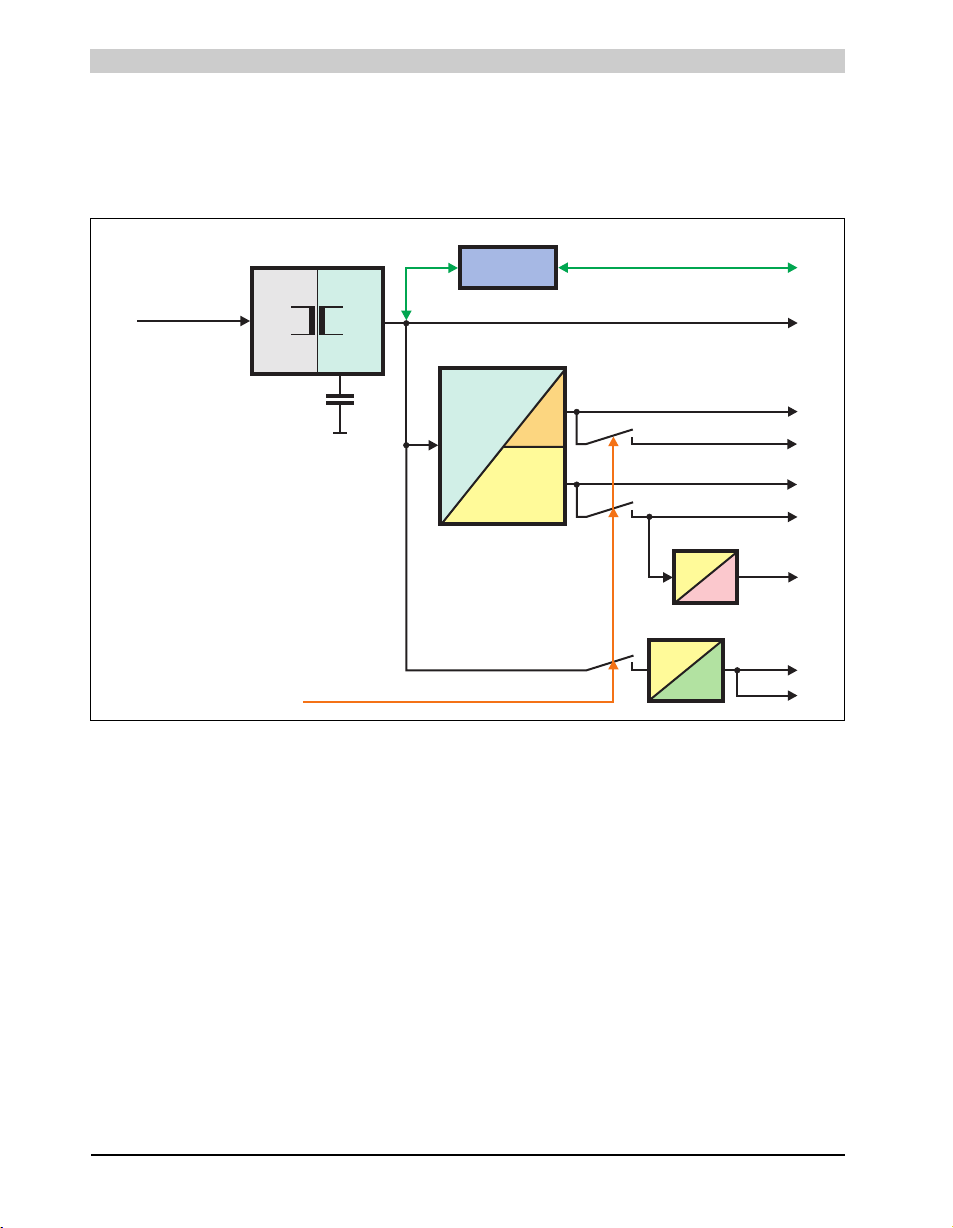
Technical data • Entire device
24V
15V
Supply voltage
+24 VDC
Buffering capacitors
(for min. 10 ms)
electrically
isolated
3V3 Standby
3V3
3V3
5V
15V
+12V
+12V
5V
5V
15V
Power On
15V
-12V
-12V
5V Standby
UPS battery
Add-on UPS
module (optional)
+12V
PCI bus
2.3 Power management
2.3.1 Block diagram - supply voltage
The following block diagram shows the simplified structure of the PPC800 supply voltage.
Figure 5: Block diagram - supply voltage
Description
The supply voltage is converted to 15 V with a DC/DC converter. These electrically isolated 15
V feed further DC/DC converters, which generate the remaining voltages.
After the system is turned on (e.g. using the power button), the voltages 3V3 and 5 V are placed
on the bus. At the 5 V output, another DC/DC converter generates -12 V, and places these on
the bus. An additional DC/DC converter generates +12 V.
The optional Add-on UPS (with battery unit) is supplied with 15 V and provides an uninterrupted
power supply from the 15 V bus during power failures.
42
Panel PC 800 User's Manual V 1.00
Page 43
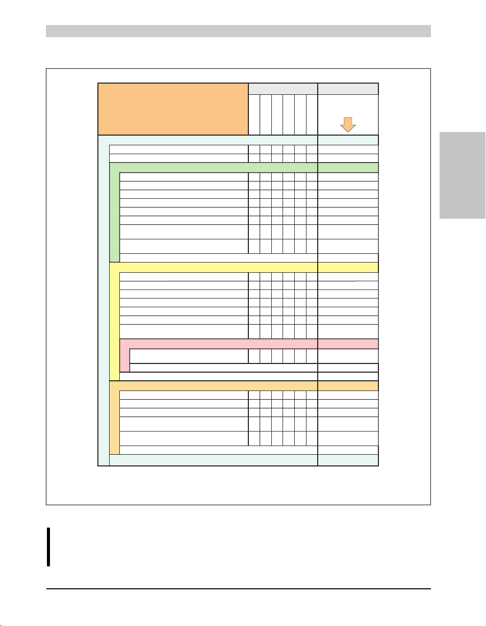
2.3.2 Power calculation with 5PC820.1505-00
N270
11
9
7.5
5PC800.B945-05
2.4
4
4
14
4
CM423 T7400L2400 L7400 U7500
CPU board, fixed device
26 30 181443
99999
System unit, fixed device
Fan kit, optional
Devices 3V3
Devices +12V
Devices -12V
This system
Devices
Power required by PCI card, optional
(max. 3 W without fan kit, max.6 W with fan kit)
1)
Power required by
PCI card, optional
(max. 3 W without fan kit, max.15 W with fan kit)
1)
Power required by PCI card, optional
(max. 1.2 W with and without fan kit)
1)
Power required by PCIec card, optional
(max. 4 W)
Power required by PCIec card, optional
(max. 4 W)
Maximum possible at +12V 75
+5V
Maximum possible at 3V3
40
3V3
+12V
-12V
Maximum possible at -12V 1.2
Total power supply
Total power supply rating (maximum) 130
Add-on UPS module, optional
7.5 7.5 7.5 7.5 7.5
5PC800.B945-03
5PC800.B945-13
5PC800.B945-04
5PC800.B945-14
5PC800.B945-00
5PC800.B945-10
5PC800.B945-01
5PC800.B945-11
5PC800.B945-02
5PC800.B945-12
1) The total performance of one PCI / PCIe card per PCI slot (= sum of power consumptions for each voltage
area) may not exceed the limits stated for operation with or without a fan kit.
Information:
All values in watts
The entries for the are maximum values.
The entries for the are determined maximum
values, but not peak values.
generator
device
Enter values in
this column
Devices 5V
512MB RAM max. 2 pcs., each 1.5 W
1024MB RAM max. 2 pcs., each 2.5 W
2048MB RAM max. 2 pcs., each 3 W
2.4 2.4 2.4 2.4 2.4
Power required by PCIe x1 card, optional
(max. 3 W without fan kit, max.20 W with fan kit)
1)
Maximum possible at +5V
System unit, fixed device
44444
65
Hard disk (slide-in compact)
44444
Power required by PCI card, optional
(max. 3 W without fan kit, max.20 W with fan kit)
1)
CompactFlash, each 1 W
Power required by
PCIe x1 card, optional
(max. 3 W without fan kit, max.10 W with fan kit)
1)
CPU boards
å
å
å
å
å
Backlight display 15"
14 14 14 14 14
USB peripheral USB1 and USB3, each 2.5 W
USB peripheral USB2, USB4 and USB5, each 5 W
Slide-in drive (hard disk, DVD-ROM, etc.)
44444
Power required by PCIec card, optional
(max. 4 W)
2) The total performance of one PCIec card per PCIec slot (= sum of power consumptions for each voltage
area) may not exceed the limits stated for operation with or without a fan kit.
2)
2)
2)
Technical data • Entire device
Section 2
Technical data
Information:
The PCIec card must not consume more than a total of 4 W (12V/5V/3V3)!
Figure 6: Power calculation for 5PC820.1505-00
43Panel PC 800 User's Manual V 1.00
Page 44
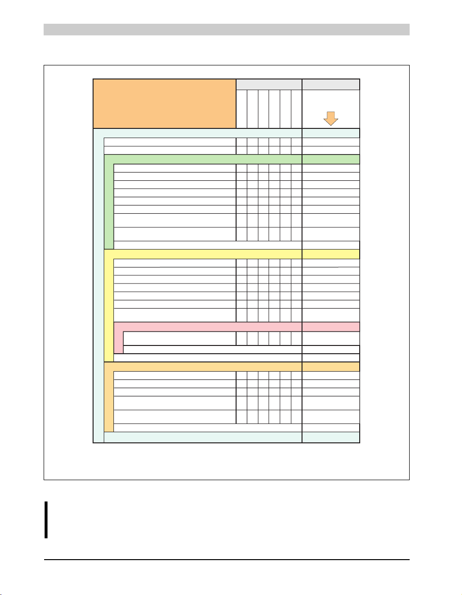
Technical data • Entire device
CM423 T7400L2400 L7400 U7500
CPU board, fixed device
26 30 181443
55555
System unit, fixed device
Fan kit, optional
Devices 3V3
Devices +12V
Devices -12V
This system
Devices
Power required by PCI card, optional
(max. 3 W without fan kit, max.6 W with fan kit)
1)
Power required by PCI card, optional
(max. 3 W without fan kit, max.15 W with fan kit)
1)
Power required by PCI card, optional
(max. 1.2 W with and without fan kit)
1)
Power required by PCIec card, optional
(max. 4 W)
Power required by PCIec card, optional
(max. 4 W)
Maximum possible at +12V 75
+5V
Maximum possible at 3V3
40
3V3
+12V
-12V
Maximum possible at -12V 1.2
Total power supply
Total power supply rating (maximum) 130
Add-on UPS module, optional
7.5 7.5 7.5 7.5 7.5
5PC800.B945-03
5PC800.B945-13
5PC800.B945-04
5PC800.B945-14
5PC800.B945-00
5PC800.B945-10
5PC800.B945-01
5PC800.B945-11
5PC800.B945-02
5PC800.B945-12
1) The total performance of one PCI / PCIe card per PCI slot (= sum of power consumptions for each voltage
area) may not exceed the limits stated for operation with or without a fan kit.
Information:
All values in watts
generator
device
The entries for the are maximum values.
The entries for the are determined maximum
values, but not peak values.
Enter values in
this column
Devices 5V
512MB RAM max. 2 pcs., each 1.5 W
1024MB RAM max. 2 pcs., each 2.5 W
2048MB RAM max. 2 pcs., each 3 W
2.4 2.4 2.4 2.4 2.4
Power required by PCIe x1 card, optional
(max. 3 W without fan kit, max.20 W with fan kit)
1)
Maximum possible at +5V
System unit, fixed device
12 12 12 12 12
65
Hard disk (slide-in compact)
44444
Power required by PCI card, optional
(max. 3 W without fan kit, max.20 W with fan kit)
1)
CompactFlash, each 1 W
Power required by PCIe x1 card, optional
(max. 3 W without fan kit, max.10 W with fan kit)
1)
CPU boards
å
å
å
å
å
Backlight display 19"
323232 32 32
USB peripheral USB1 and USB3, each 2.5 W
USB USB2, USB4 and USB5, each 5 Wperipheral
Slide-in drive (hard disk, DVD-ROM, etc.)
44444
Power required by PCIec card, optional
(max. 4 W)
2) The total performance of one PCIec card per PCIec slot (= sum of power consumptions for each voltage
area) may not exceed the limits stated for operation with or without a fan kit.
2)
2)
2)
N270
11
5
7.5
5PC800.B945-05
2.4
12
4
32
4
2.3.3 Power calculation with 5PC820.1906-00
Information:
The PCIec card must not consume more than a total of 4 W (12V/5V/3V3)!
44
Figure 7: Power calculation for 5PC820.1906-00
Panel PC 800 User's Manual V 1.00
Page 45
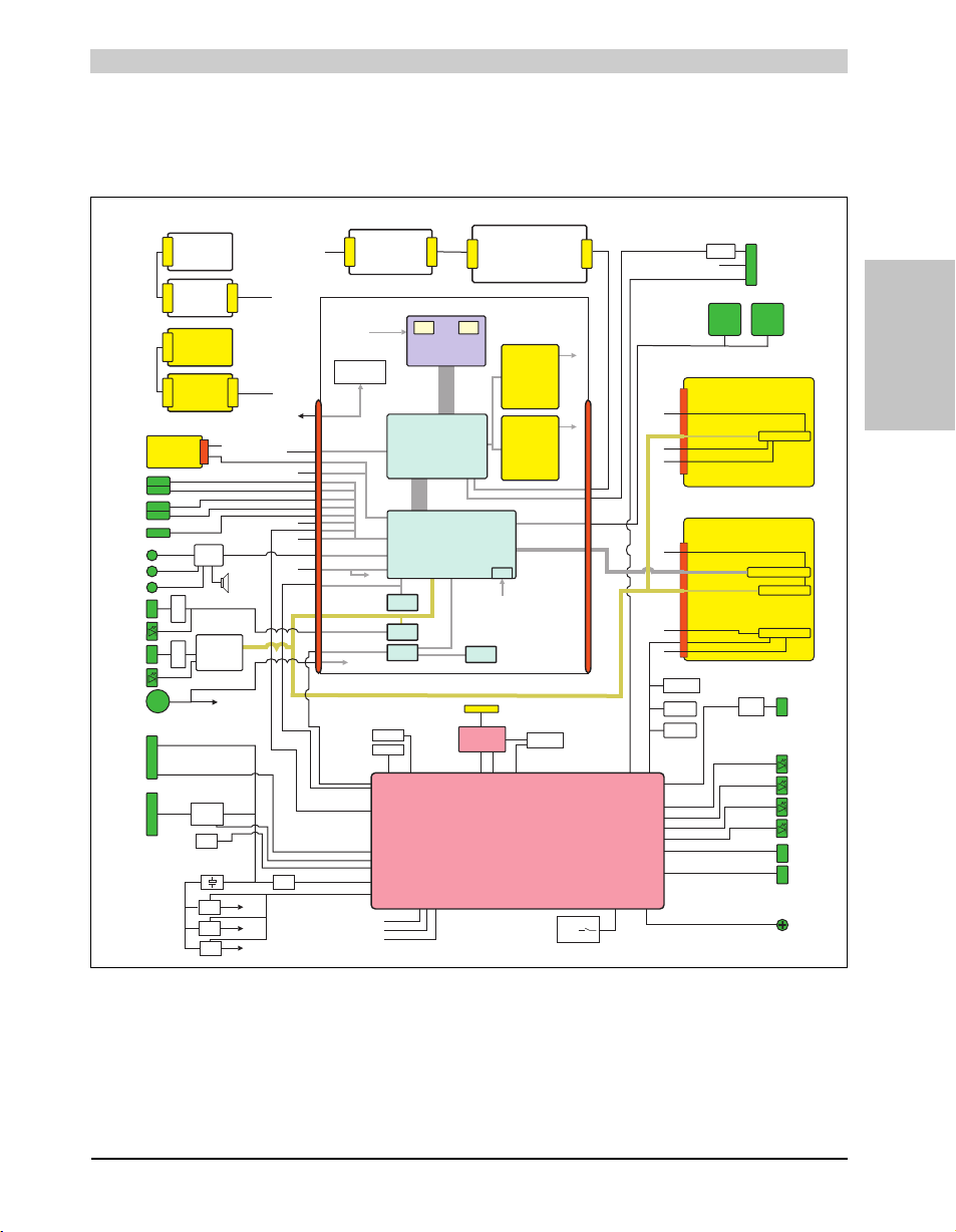
Technical data • Entire device
Backlight
Backlight inverter
UpDate
Controller
UpDate (JTAG)
Serial EEPROM
JTAG
SPI
SPI
ETH 1 LED
green-orange/orange
ETH 2 LED
green-orange/orange
PPCTouch IF
Touch PCB
Touch pad
Key PAD
(optional)
Key PCB
(optional)
PPC PW keys
Supply
voltage
3-pin
DC/DC
Isolated
15.6V
Temp .
Sensor
15.6V
I2C
Power good
130W power supply
UPSI
Temperature
sensor 1
Temperature
sensor 2
8-bit configuration
switch
and
config R´s
RAM 128 kB
Serial Flash
Serial EEPROM
Factory Settings
Ethernet
Controller
Intel 82574
Monitor / Panel
SDL1 / DVI-I
Power / LED
red/green
HDD LED
yellow
Link1 LED
yellow
RUN Led
red/green
Power button
Ethernet
ETH1
Ethernet
ETH2
USB1
USB2
USB3
USB4
USB5
Front
RS232 COM1
Hex switch
Cmos profile
Optional
slide-in
SATA
hard disk
Compact Flash
Slot 1
Master
Compact Flash
Slot 2
Slave
Batterie
950 mAh
V battery
Line driver
RS232
Buffering 10 ms
DC/DC
switching
ADC
DC/DC
switching
DC/DC
switching
+ 5V
+ 3.3V
+ 12V
+ 15.6V
USB0
+5V
USB2
USB4
Gbit LAN1
PCIe (0)
PCIe (1-4)
I2C module
LPC bus
USB 6
I2C
Power control
Power good
USB7
SM bus
USB5
PCIe ()
SATA 1
COM 1
SDL IF
I2C
PPC PW keys
PPCTouch IF
PPC BKL
PPC BKL
+12V
SATA 0
USB3
USB1
FPGA MTCX Controller
Reset button
Analog RGB
Analog RGB
SDL IF
Gbit LAN
transformer
Gbit LAN
transformer
SDVO B
TMDS
Sil 1362A
LVDS
TFT module
Voltage supply
DC/DC controller
North Bridge
Intel 82945GME
Core
Core
South Bridge
ICH7-DH
Intel 82801GHM
CPU temperature
SO-DIMM
Module 1
256MB - 2GB
SO-DIMM
Module 2
256MB - 2GB
ETH Controller
Realtek 8111B
SM Bus
AC97 / HD Audio
LPC bus
PCI bus
PCIexpress (Lane0-4)
Gbit Ethernet
I2C
V battery
V battery
SPI
PCIe (5)
SM bus
RTC
+12V
System bus
533 / 667MHz
Memory bus
533 / 667MHz
DMI interface
Analog RGB
SATA 0
SATA 1
USB0
USB1
USB2
USB3
USB4
USB5
USB6
USB7
BIOS
Flash
Board
controller
Hardware
monitor
SM bus
SM bus
CPU
Intel Core2 Duo
Core Duo, Celeron M,
Atom N270
LVDS A B
SDVO B
Prim IDE
Mic
Line In
Line Out
HD audio
Buzzer
HD Audio
Sound
SM bus
USB5
PCI bus
I2C
SATA 1
SM bus
USB7
I2C
1 slot Ife bus 1PCIe
USB
I2C
PCIe (2)
SM bus
PCIe X1 Slot 1
2 slot bus 1PCI / 1PCIe
PCIe X1 slot 2
Slide-in slot 1
32-bit PCI bus slot 3
USB
I2C
SATA2
PCIe ()
PCI bus
SM bus
PCIe(2)
DataOut
2.4 Block diagram
The following block diagram shows the simplified system unit structure with a 945GME CPU
board.
Section 2
Technical data
Figure 8: Block diagram
45Panel PC 800 User's Manual V 1.00
Page 46
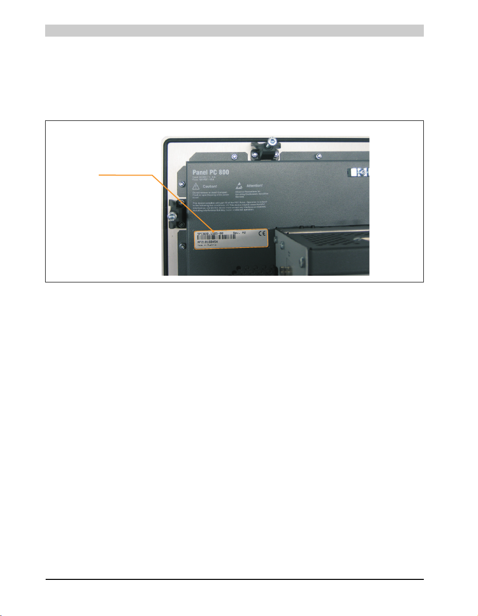
Technical data • Entire device
Serial number sticker
2.5 Serial number sticker
Each B&R device is assigned a unique serial number label with a bar code (type 128), which
allows the device to be clearly identified. This serial number represents all of the components
built into the system (model number, name, revision, serial number, delivery date and duration
of warranty).
Figure 9: Serial number sticker (back)
46
Panel PC 800 User's Manual V 1.00
Page 47
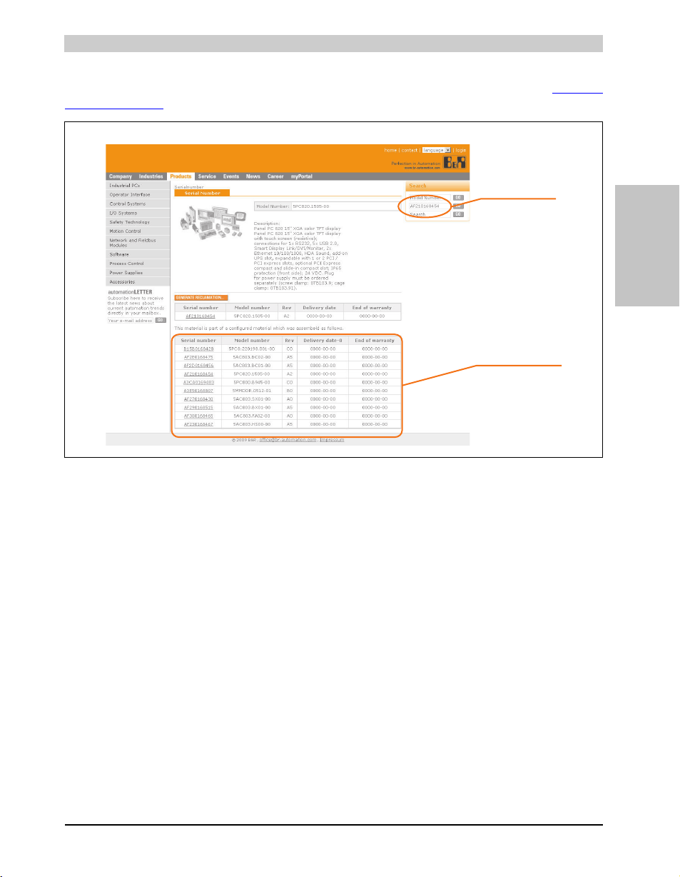
Technical data • Entire device
Enter serial number
e.g. AF210168454
List of installed
components according
to serial number search
This information can also be found on the B&R homepage. Enter the serial number of the entire
device (found behind the front door) in the serial number search field on the start page www.br-
automation.com. The search provides you with a detailed list of the individual components.
Section 2
Technical data
Figure 10: Example of serial number search
47Panel PC 800 User's Manual V 1.00
Page 48
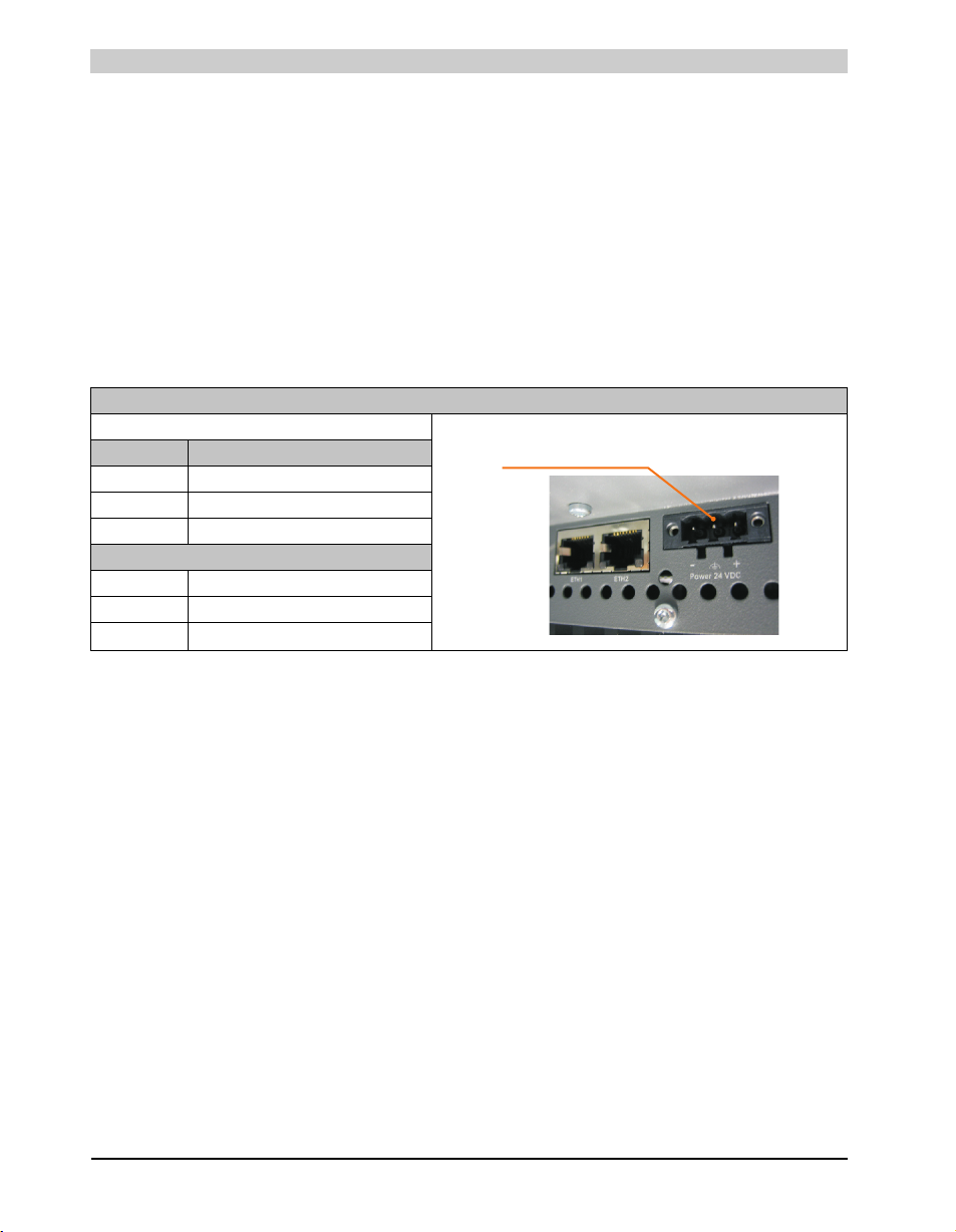
Technical data • Entire device
123
Supply voltage + 24 VDC
2.6 Device interfaces
2.6.1 +24 VDC supply voltage
The 3-pin socket required for the supply voltage connection is not included in delivery. This can
be ordered from B&R using the model number 0TB103.9 (screw clamp) or 0TB103.91 (cage
clamp).
The pin assignments can be found either in the following table or printed on the PPC800 housing.
The supply voltage is protected internally by a soldered fuse (15A, fast-acting), so that the device
cannot be damaged if there is an overload (fuse replacement necessary) or if the voltage supply
is connected incorrectly (reverse polarity protection - fuse replacement not necessary). The
device must be returned to B&R for repairs if the fuse is blown because of an error.
Supply voltage
Protected against reverse polarity 3-pin, male
Pin Description
1+
2 Functional ground
3-
Accessories
0TB103.9 Plug 24 V 5.08 3p screw clamps
0TB103.91 Plug 24 V 5.08 3p cage clamps
48
Table 24: Supply voltage connection + 24VDC
Panel PC 800 User's Manual V 1.00
Page 49
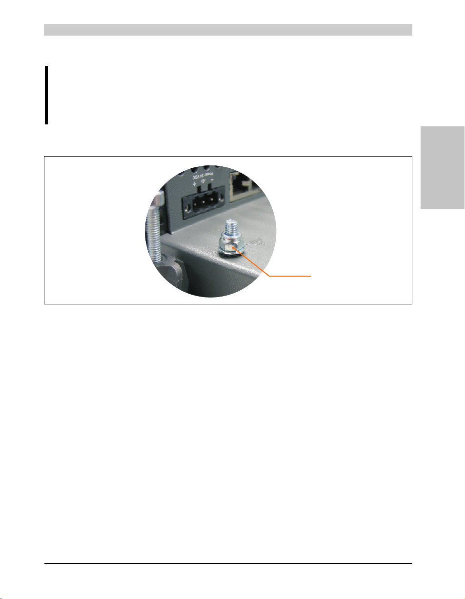
Technical data • Entire device
Ground connection
Ground
Caution!
The pin's connection to the functional ground (pin 2, e.g. switching cabinet) should
be as short as possible. We recommend using the largest possible conductor cross
section on the supply plug.
The grounding connection is located on the top right on the back of the PPC800 system.
Figure 11: Ground connection
Section 2
Technical data
The M4 self-locking nut can be used, for example, to fasten a copper strip that is built into the
PPC800 at a central grounding point in the switching cabinet or system. The largest possible
conductor cross section should be used (at least 2.5 mm²).
49Panel PC 800 User's Manual V 1.00
Page 50
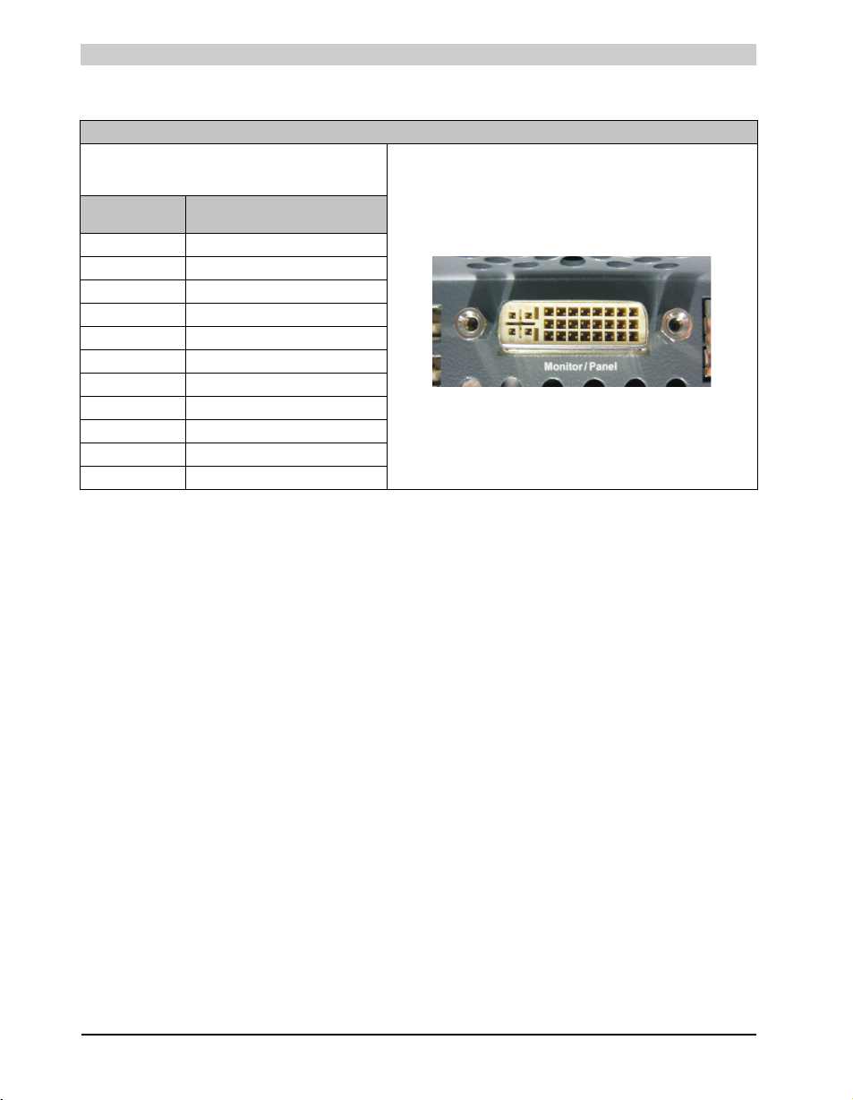
Technical data • Entire device
2.6.2 Monitor / Panel connection - SDL (Smart Display Link / DVI)
Monitor / Panel connection - SDL (Smart Display Link / DVI)
The following will provide an overview of the video signals
available on the monitor/panel output.
For details, see technical data for the CPU board being used.
CPU board Video signals with all
5PC800.B945-00 RGB, DVI, SDL
5PC800.B945-01 RGB, DVI, SDL
5PC800.B945-02 RGB, DVI, SDL
5PC800.B945-03 RGB, DVI, SDL
5PC800.B945-04 RGB, DVI, SDL
5PC800.B945-05 RGB, DVI, SDL
5PC800.B945-10 RGB, DVI, SDL
5PC800.B945-11 RGB, DVI, SDL
5PC800.B945-12 RGB, DVI, SDL
5PC800.B945-13 RGB, DVI, SDL
5PC800.B945-14 RGB, DVI, SDL
system unit variations
Table 25: Monitor / Panel connection - RGB, DVI, SDL
50
Panel PC 800 User's Manual V 1.00
Page 51
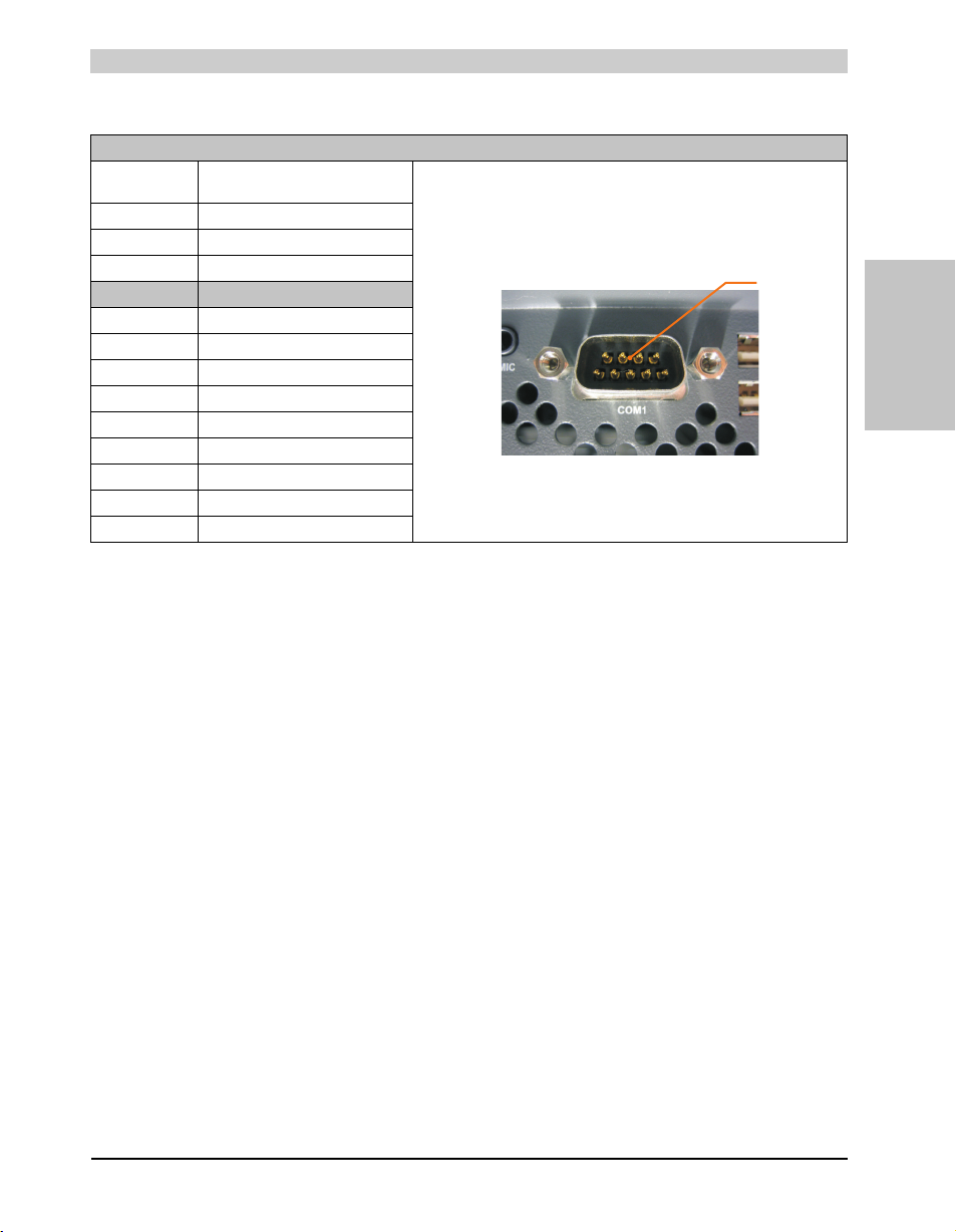
2.6.3 Serial interface COM1
COM1
Technical data • Entire device
1)
9-pin DSUB, male
Type RS232, modem-capable, not
UART 16550-compatible, 16-byte FIFO
Transfer rate Max. 115 kBaud
Cable length Max. 15 meters
Pin Assignment
1 DCD
2RXD
3TXD
4DTR
5GND
6DSR
7RTS
8CTS
9RI
electrically isolated
Serial interfaces COM1
Table 26: Pin assignments - COM1
1) The interfaces, etc. available on the device or module were numbered accordingly for easy identification. This numbering can differ from
the numbering used by the particular operating system.
Section 2
Technical data
51Panel PC 800 User's Manual V 1.00
Page 52
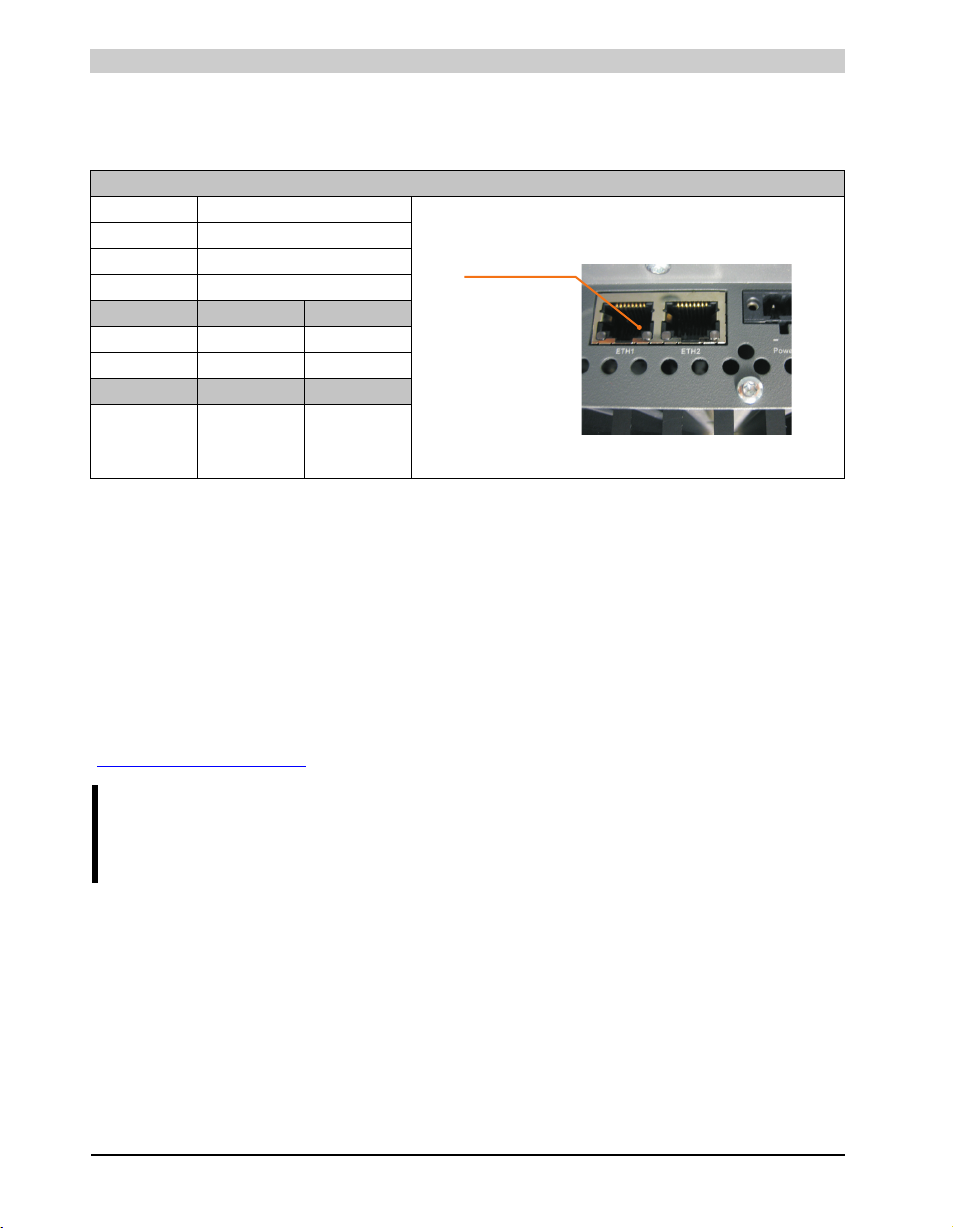
Technical data • Entire device
Ethernet 1
(ETH1)
(10/100/1000)
2.6.4 Ethernet 1 (ETH1)
This Ethernet controller is integrated in the main board and is fed outwards via the system unit.
Ethernet 1 connection (ETH1
Controller Realtek RTL8111B/C
Cabling S/STP (Cat5e)
Transfer rate 10/100/1000 MBit/s
Cable length max. 100 m (min. Cat5e)
Speed LED On Off
Green 100 Mbit/s 10 Mbit/s
Orange 1000 Mbit/s -
Link LED On Off
Orange Link
(Ethernet network
connection
available)
2)
3)
4)
Activity (blinking)
(Data transfer in
progress)
Table 27: Ethernet connection (ETH1)
1) The interfaces, etc. available on the device or module were numbered accordingly for easy identification. This numbering can differ from
the numbering used by the particular operating system.
2) The Realtek RTL8111C is integrated in the CPU boards 5PC800.B945-05, 5PC800.B945-10, 5PC800.B945-11, 5PC800.B945-12,
5PC800.B945-13, 5PC800.B945-14.
3) Change-over takes place automatically.
4) The 10 MBit/s transfer speed / connection is only present if the Link LED is simultaneously active.
1)
)
RJ45 twisted pair (10BaseT/100BaseT), female
Driver support
A special driver is necessary for operating the Realtek Ethernet controllers RTL8111B/C. The
necessary software can be downloaded from the download area on the B&R homepage
(www.br-automation.com
).
Information:
Required drivers can only be downloaded from the B&R homepage, not from
manufacturers' pages.
52
Panel PC 800 User's Manual V 1.00
Page 53
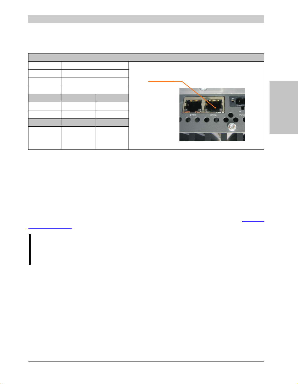
Technical data • Entire device
Ethernet 2 (10/100/1000)
(ETH2)
2.6.5 Ethernet 2 (ETH2)
This Ethernet controller is integrated in the CPU board and is fed outwards via the system unit.
Ethernet 2 connection (ETH2
Controller Intel 82574
Cabling S/STP (Cat5e)
Transfer rate 10/100/1000 MBit/s
Cable length max. 100 m (min. Cat5e)
Speed LED On Off
Green 100 Mbit/s 10 Mbit/s
Orange 1000 Mbit/s -
Link LED On Off
Orange Link
(Ethernet network
connection
available)
2)
3)
Activity (blinking)
(Data transfer in
progress)
Table 28: Ethernet connection (ETH2)
1) The interfaces, etc. available on the device or module were numbered accordingly for easy identification. This numbering can differ from
the numbering used by the particular operating system.
2) Change-over takes place automatically.
3) The 10 MBit/s transfer speed / connection is only present if the Link LED is simultaneously active.
1)
)
RJ45 twisted pair (10BaseT/100BaseT), female
Driver support
Section 2
Technical data
A special driver is necessary for operating the Intel Ethernet controller 82574. The necessary
software can be downloaded from the download area on the B&R homepage (www.br-
automation.com).
Information:
Required drivers can only be downloaded from the B&R homepage, not from
manufacturers' pages.
53Panel PC 800 User's Manual V 1.00
Page 54
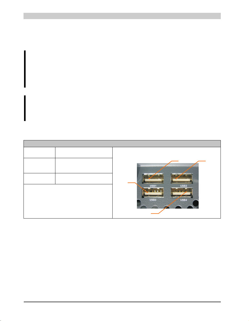
Technical data • Entire device
USB2
USB1
USB4
USB3
2.6.6 USB interfaces (USB1, 2, 3, 4)
The PPC800 devices have a USB 2.0 (Universal Serial Bus) host controller with multiple USB
ports, two of which are on the outside for easy access.
Warning!
Peripheral USB devices can be connected to the USB interfaces. Due to the vast
number of USB devices available on the market, B&R cannot guarantee their
performance. B&R does ensure the performance of all USB devices that they
provide.
Caution!
Because of general PC specifications, this interface should be handled with extreme
care with regard to EMC, location of cables, etc.
USB1,2,3,4
Universal Serial Bus (USB1, USB2, USB3, USB4)
Transfer rate Low speed (1.5 MBit/s), Full speed (12
Power supply
USB1, USB3
USB2, USB4
Maximum
Cable length
MBit/s) up to High speed (480 MBit/s)
2)
Max. 500 mA
Max. 1 A
5 m (without hub)
1)
4 x USB type A, female
Table 29: USB1, USB2, USB3, USB4 connection
1) The interfaces, etc. available on the device or module were numbered accordingly for easy identification. This numbering can differ from
the numbering used by the particular operating system.
2) For safety, every USB port is equipped with a maintenance free "USB current-limiting circuit breaker" (max. 500 mA or 1 A).
54
Panel PC 800 User's Manual V 1.00
Page 55
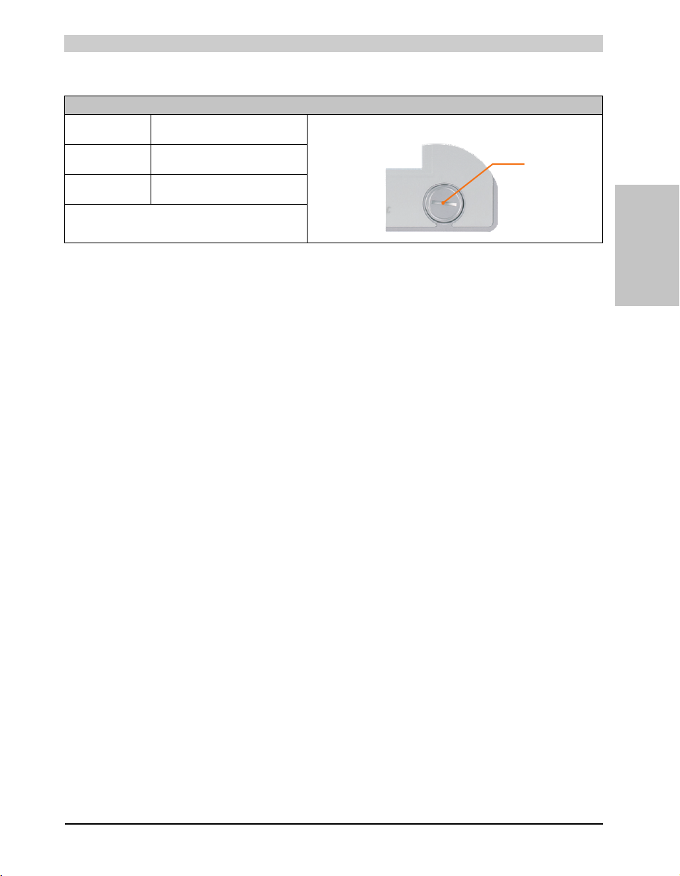
USB5
USB front
Technical data • Entire device
Universal Serial Bus (USB5)
Transfer rate Low speed (1.5 MBit/s), full speed
Power supply
USB5
Maximum
Cable length
(12 MBit/s), to high speed (480 MBit/s)
2)
Max. 1 A
5 m (without hub)
1)
1 x USB type A, female
Table 30: USB5 connection
1) The interfaces, etc. available on the device or module were numbered accordingly for easy identification. This numbering can differ from
the numbering used by the particular operating system.
2) For safety, the USB port is equipped with a maintenance free "USB current-limiting circuit breaker" (max. 1 A)
Section 2
Technical data
55Panel PC 800 User's Manual V 1.00
Page 56
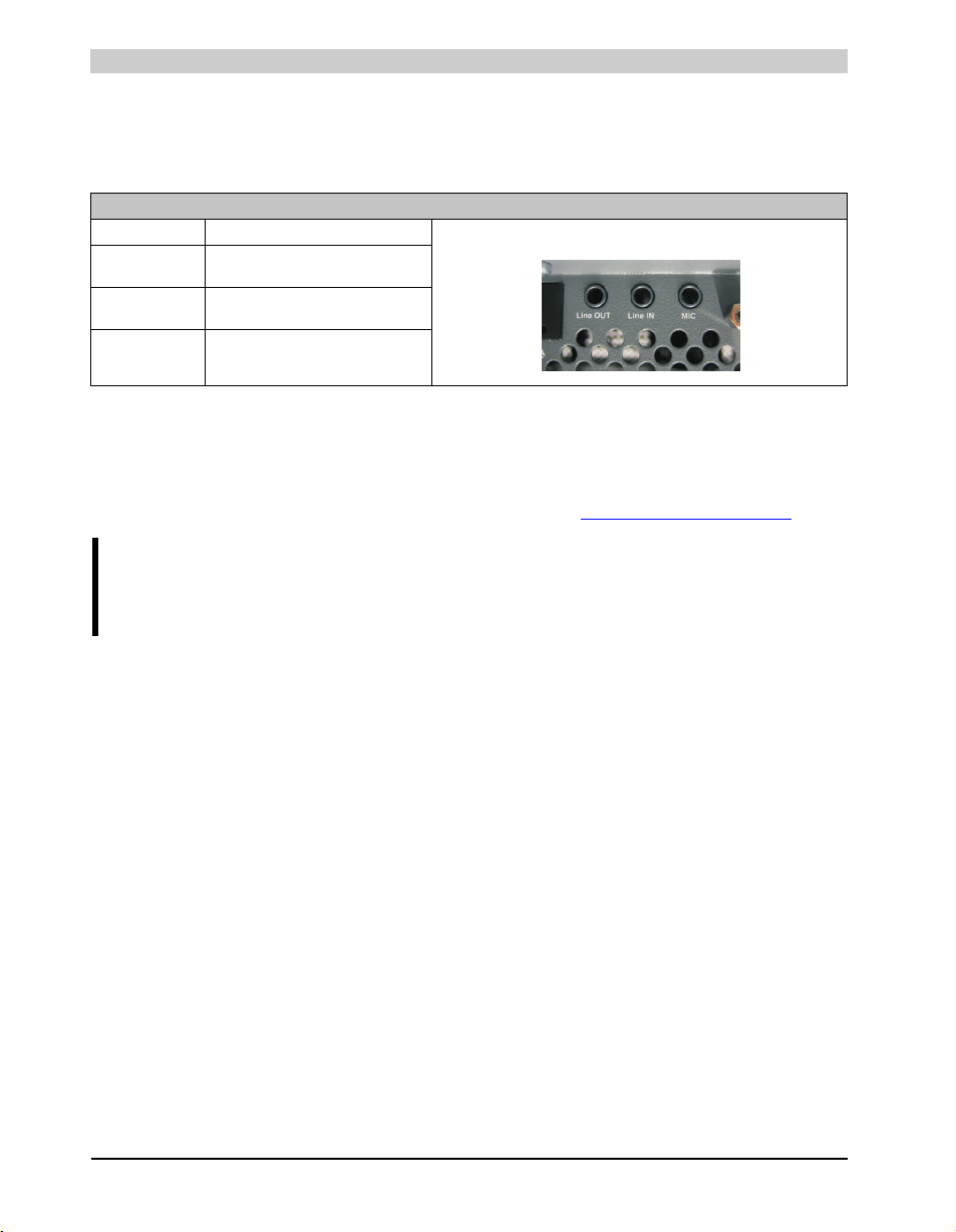
Technical data • Entire device
2.6.7 MIC, Line IN, Line OUT
All PPC800 systems include an HDA compatible sound chip with access to the channels MIC,
Line IN and Line OUT from the outside.
MIC, Line IN, Line OUT
Controller Realtek ALC 662 3.5 mm jack, female
MIC Connection of a mono microphone with a
Line IN Stereo Line IN signal supplied via 3.5 mm
Line OUT Connection of a stereo sound device (e.g.
3.5 mm stereo (headphone) jack.
jack.
amplifier) via a 3.5 mm jack.
Table 31: MIC, Line IN, Line OUT
Driver support
A special driver is necessary for operating the audio controller. The necessary software can be
downloaded from the download area on the B&R homepage (www.br-automation.com
).
Information:
Required drivers can only be downloaded from the B&R homepage, not from
manufacturers' pages.
56
Panel PC 800 User's Manual V 1.00
Page 57
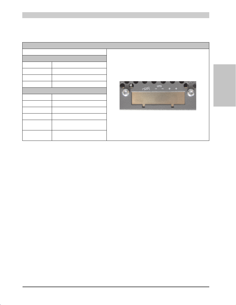
Technical data • Entire device
123456
2.6.8 Add-on UPS slot
An optional Automation PC add-on UPS module can be installed here.
Add-on UPS slot
Add-on UPS + accessories
5AC600.UPSI-00 Add-on UPS module
5AC600.UPSB-00 Battery unit 5 Ah
5CAUPS.0005-00 UPS cable 0.5 m
5CAUPS.0030-00 UPS cable 3 m
Pin assignments with mounted add-on UPS module
1+
2+
3-
4-
5 NTC (for battery temperature
measurement
6 NTC (for battery temperature
measurement
Table 32: Add-on UPS slot (with and without mounted UPS)
For more on the UPS module, see chapter 6 "Accessories", section 6 "Uninterruptible power
supply", on page 300.
Section 2
Technical data
57Panel PC 800 User's Manual V 1.00
Page 58
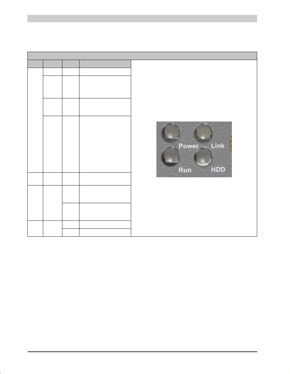
Technical data • Entire device
2.6.9 Status LEDs
The status LEDs are on the back of the system unit.
Status LEDs
LED Color Meaning
Green On Supply voltage OK
The system is in standby mode
Red On
Orange
1)
Power
red /
green
HDD Yellow On
Link Yellow
Run Green
(S5: soft-off mode or S4:
Hibernate mode -Suspend-toDisk)
Supply voltage not OK; the
On
system is operating on battery
power.
MTCX upgrade service
function: A red/green blinking
power LED indicates a faulty
or incomplete MTCX upgrade.
The MTCX runs using the
Blinking
firmware version installed
when delivered. This could be
caused by a power failure
during an MTCX upgrade. An
MTCX upgrade must be
performed again.
Signals IDE drive access (CF,
HDD, CD, etc.)
Indicates an active SDL
On
connection on the monitor /
panel plug.
An active SDL connection has
Blinking
been interrupted by a loss of
power in the display unit.
On Application running
Off Application is not running
Table 33: Data - status LEDs
1) Only lit when add-on UPS module is installed.
58
Panel PC 800 User's Manual V 1.00
Page 59
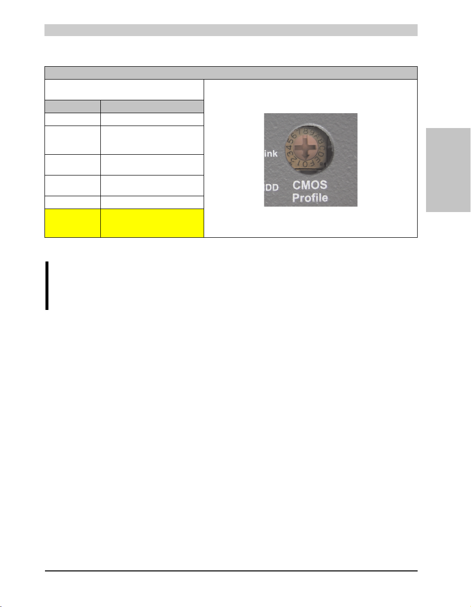
Technical data • Entire device
2.6.10 CMOS profile switch
CMOS profile switch
Different BIOS default value profiles can be defined using the
16-position CMOS profile switch.
Switch position Description
0 Profile 0: Default profile reserved.
1 Profile 1: Optimized for system units
2 Profile 2: Optimized for
3 Profile 3: Optimized for the
4 Profile 4: Reserved
5 Profile 5: Optimized for system
5PC810.SX01-00 and 5PC810.SX0200
5PC810.SX05-00 system unit
5PC820.SX01-00 system unit
units 5PC820.1505-00 and
5PC820.1906-00
Table 34: CMOS profile switch
Information:
The switch position that is set upon delivery represents the optimum BIOS default
values for this system and should therefore not be changed.
Section 2
Technical data
The position of the CMOS profile switch is is displayed in the BIOS setup pages and in the B&R
ADI Control Center, among other places.
59Panel PC 800 User's Manual V 1.00
Page 60
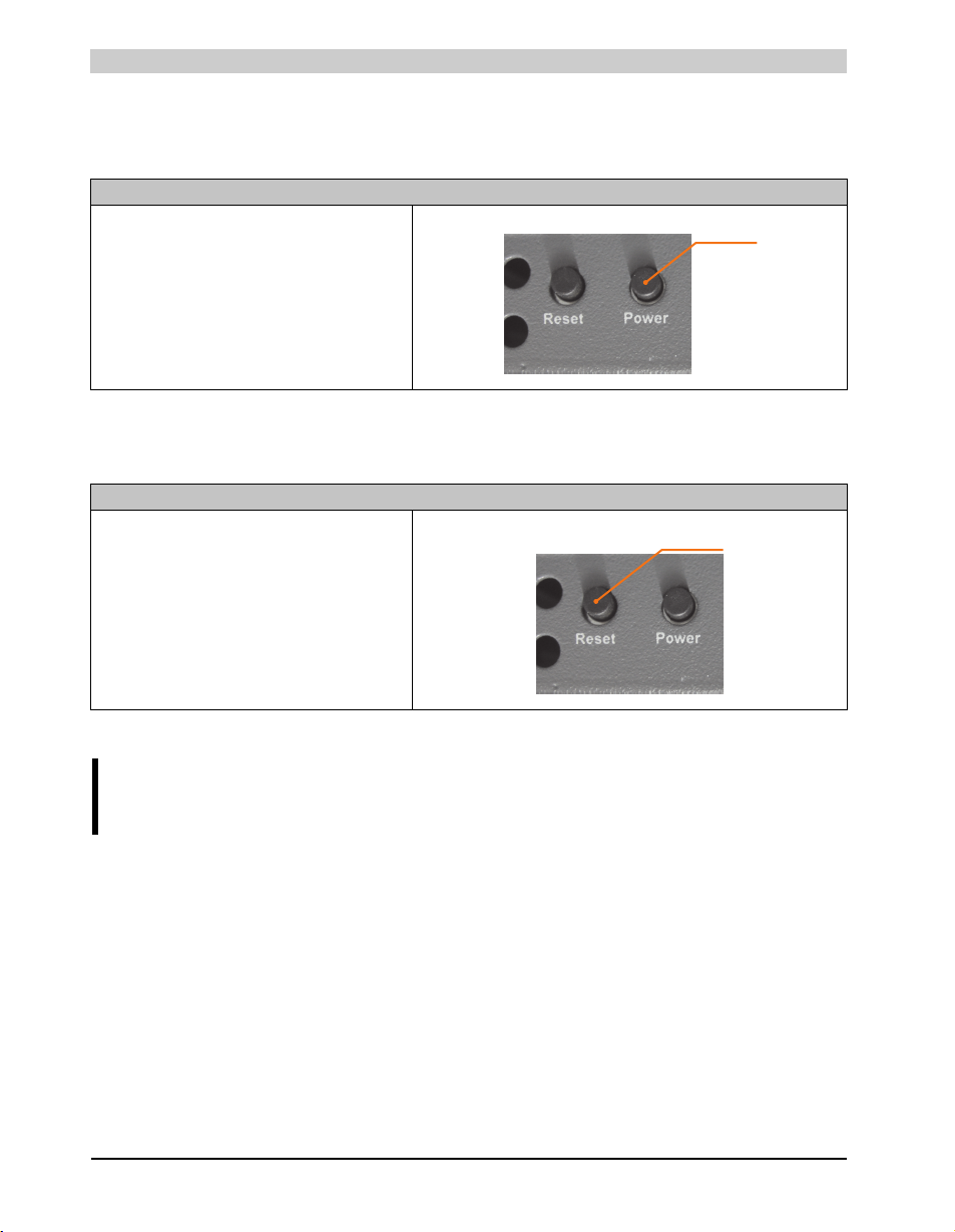
Technical data • Entire device
Power button
Reset button
2.6.11 Power button
The power button has a variety of functions due to full ATX power supply support.
Power button
The power button acts like the on/off switch on a normal
desktop PC with ATX power supply:
Press and release ... Switches on PPC800 or shuts down
operating system and switches off the PPC800.
Press and hold ... ATX power supply switches off without
shutting down the PPC800 (data could be lost!).
Pressing the power button does not reset the MTCX
processor.
Table 35: Power button
2.6.12 Reset button
Reset button
Pushing the reset button results in a hardware-reset, PCIreset. The PPC800 is restarted (cold restart).
The MTCX processor is not reset when the reset button is
pressed.
Table 36: Reset button
Warning!
A system reset can cause data to be lost!
60
Panel PC 800 User's Manual V 1.00
Page 61
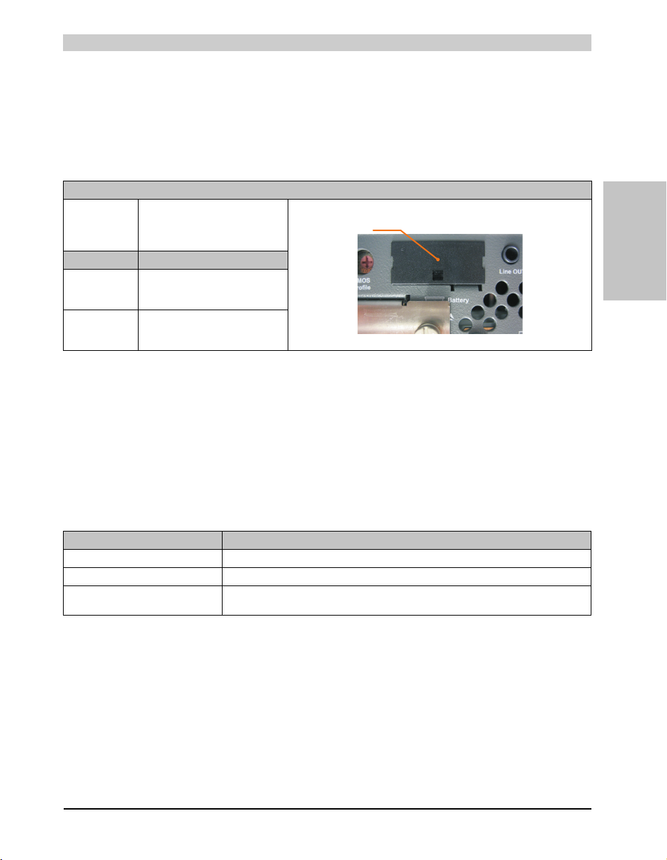
Technical data • Entire device
Battery
2.6.13 Battery
The lithium battery (3 V, 950 mAh) buffers the internal real-time clock (RTC) as well as the
individually saved BIOS settings and is located behind the black cover. The buffer duration of the
battery is at least 2½ years (at 50°C, 8.5 µA current requirements of the supplied components
and a self discharge of 40%). The battery is subject to wear and should be replaced regularly (at
least following the specified lifespan).
Battery
Battery
Type
Removable
Lifespan
Accessories Short description
0AC201.91 Lithium batteries, 4 pcs.
4A0006.00-000 Lithium battery, 1 pc.
Renata 950 mAh
Yes, accessible from the outside
Lithium batteries, 4 pcs.,
3 V / 950 mAh, button cell
Lithium batteries, 1 pcs.,
3 V / 950 mAh, button cell
2½ years
1)
Table 37: Battery
1) At 50°C, 8.5 µA of the supplied components and a self discharge of 40%.
Battery status evaluation
Section 2
Technical data
The battery status is evaluated immediately following start-up of the device and is subsequently
checked by the system every 24 hours. The battery is subjected to a brief load (1 second) during
the measurement and then evaluated. The evaluated battery status is displayed in the BIOS
Setup pages (under Advanced - Main board monitor) and in the B&R Control Center (ADI driver),
but can also be read in a customer application via the ADI Library.
Battery status Meaning
N/A Hardware, i.e. firmware used is too old and does not support read.
Good Data buffering is guaranteed
Bad Data buffering is guaranteed for approx. another 500 hours from the point in time that the battery
capacity is determined to be BAD (insufficient).
Table 38: Meaning of battery status
61Panel PC 800 User's Manual V 1.00
Page 62
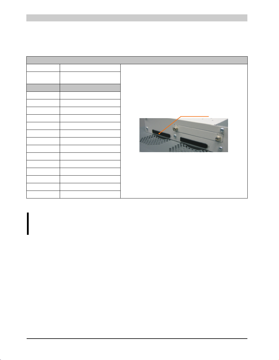
Technical data • Entire device
CompactFlash slot 1
2.6.14 CompactFlash slot 1
This CompactFlash slot is a fixed part of an PPC800 system and is internally connected with the
chipset via IDE PATA. Type I CompactFlash cards are supported.
CompactFlash slot (CF1)
Connection PATA Master
CompactFlash
Type Type I
Accessories Short description
5CFCRD.0512-04 512 MB B&R CompactFlash card
5CFCRD.1024-04 1024 MB B&R CompactFlash card
5CFCRD.2048-04 2048 MB B&R CompactFlash card
5CFCRD.4096-04 4096 MB B&R CompactFlash card
5CFCRD.8192-04 8192 MB B&R CompactFlash card
5CFCRD.016G-04 16 GB B&R CompactFlash card
5CFCRD.0064-03 CompactFlash 64 MB SSI
5CFCRD.0128-03 CompactFlash 128 MB SSI
5CFCRD.0256-03 CompactFlash 256 MB SSI
5CFCRD.0512-03 CompactFlash 512 MB SSI
5CFCRD.1024-03 CompactFlash 1024 MB SSI
5CFCRD.2048-03 CompactFlash 2048 MB SSI
5CFCRD.4096-03 CompactFlash 4096 MB SSI
5CFCRD.8192-03 CompactFlash 8192 MB SSI
Table 39: CompactFlash slot (CF1)
Warning!
Turn off power before inserting or removing the CompactFlash card!
62
Panel PC 800 User's Manual V 1.00
Page 63
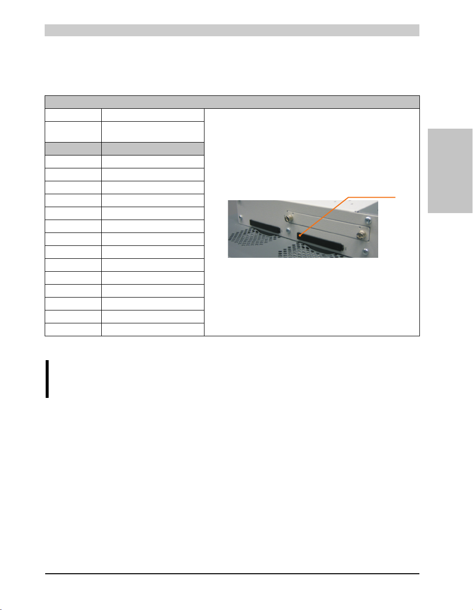
Technical data • Entire device
CompactFlash slot 2
2.6.15 CompactFlash slot 2
This CompactFlash slot is a fixed part of an PPC800 system and is internally connected with the
chipset via IDE PATA. Type I CompactFlash cards are supported.
CompactFlash slot (CF2)
Connection PATA Slave
CompactFlash
Type Type I
Accessories Short description
5CFCRD.0512-04 512 MB B&R CompactFlash card
5CFCRD.1024-04 1024 MB B&R CompactFlash card
5CFCRD.2048-04 2048 MB B&R CompactFlash card
5CFCRD.4096-04 4096 MB B&R CompactFlash card
5CFCRD.8192-04 8192 MB B&R CompactFlash card
5CFCRD.016G-04 16 GB B&R CompactFlash card
5CFCRD.0064-03 CompactFlash 64 MB SSI
5CFCRD.0128-03 CompactFlash 128 MB SSI
5CFCRD.0256-03 CompactFlash 256 MB SSI
5CFCRD.0512-03 CompactFlash 512 MB SSI
5CFCRD.1024-03 CompactFlash 1024 MB SSI
5CFCRD.2048-03 CompactFlash 2048 MB SSI
5CFCRD.4096-03 CompactFlash 4096 MB SSI
5CFCRD.8192-03 CompactFlash 8192 MB SSI
Table 40: CompactFlash slot (CF2)
Section 2
Technical data
Warning!
Turn off power before inserting or removing the CompactFlash card!
63Panel PC 800 User's Manual V 1.00
Page 64
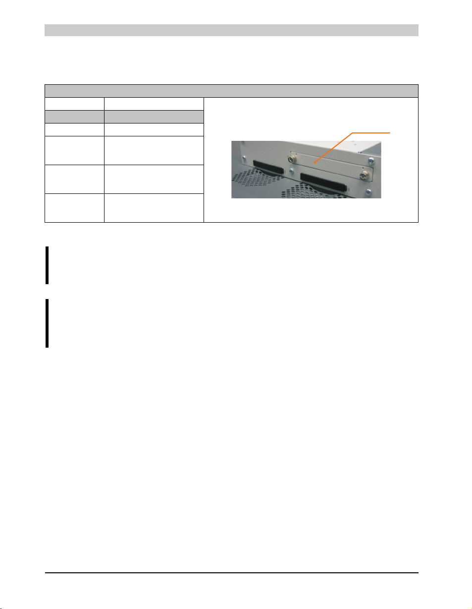
Technical data • Entire device
Slide-in compact
drive
2.6.16 Slide-in compact slot
The slide-in compact slot is internally connected with the chipset via SATA I.
Slide-in compact slot
Connection SATA I
Accessories Short description
5AC803.BC02-00 PPC800 option slide-in compact
5AC801.HDDI-00 APC810 and PPC800 slide-in
5AC801.HDDI-02 APC810 and PPC800 slide-in
5AC801.SSDI-00 APC810 and PPC800 slide-in
compact HDD
40GB EE25
compact HDD
160GB EE25
compact SSD
32GB (SLC)
Table 41: Slide-in compact slot
Information:
The option 5AC803.BC02-00 is required for the use of slide-in compact drives.
Information:
The SATA I interface allows data carriers to be exchanged during operation (hotplug). To utilize this capability, it must be supported by the operating system.
64
Panel PC 800 User's Manual V 1.00
Page 65
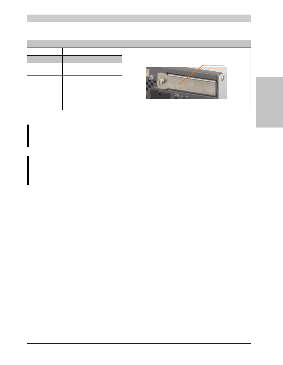
Technical data • Entire device
PCIec card slot
2.6.17 PCIec slot (card slot)
Slide-in compact slot
Accessories Short description
5AC803.BC01-00 PPC800 option PCI Express
5ACPCC.ETH0-00 PCIec Ethernet card 10/100/1000
5ACPCC.MPL0-00 PCIec POWERLINK MN 2-port
compact
PCIec Ethernet plug-in card,
1 Ethernet interface 10/100/1000
PCIec POWERLINK plug-in card, 2
POWERLINK interfaces
Table 42: Slide-in compact slot
Information:
The option 5AC803.BC01-00 is required for the use of PCIec plug-in cards.
Information:
Only B&R PCIec cards that were specially designed for the Automation PC 820 and
Panel PC 800 can be used.
Section 2
Technical data
More information can be found in section 3.8 "Plug-in cards", on page 89.
65Panel PC 800 User's Manual V 1.00
Page 66
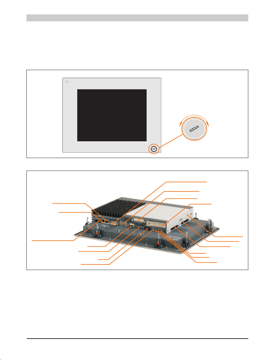
Technical data • Individual components
PANELPC
O
p
e
n
C
l
o
s
e
USB connection on front
PCIec Card slot
Add-on UPS slot
USB 1, USB2, USB3, USB4
Ethernet 2 (10/100/1000)
(ETH2)
HDA Sound
MIC, Line IN, Line OUT
Reset button
COM1 RS232
Supply voltage + 24 VDC
Battery
LED for: Power,
Link1, Run, HDD
Power button
Ethernet 1
(ETH1)
(10/100/1000)
Monitor/Panel
SDL (Smart Display Link) / DVI
CMOS profile switch
CompactFlash slot CF1
CompactFlash slot CF2
Slide-in compact slot
3. Individual components
3.1 System units
3.1.1 Panel PC 5PC820.1505-00
Figure 12: Front view - 5PC820.1505-00
66
Figure 13: Rear view 5PC820.1505-00
Panel PC 800 User's Manual V 1.00
Page 67
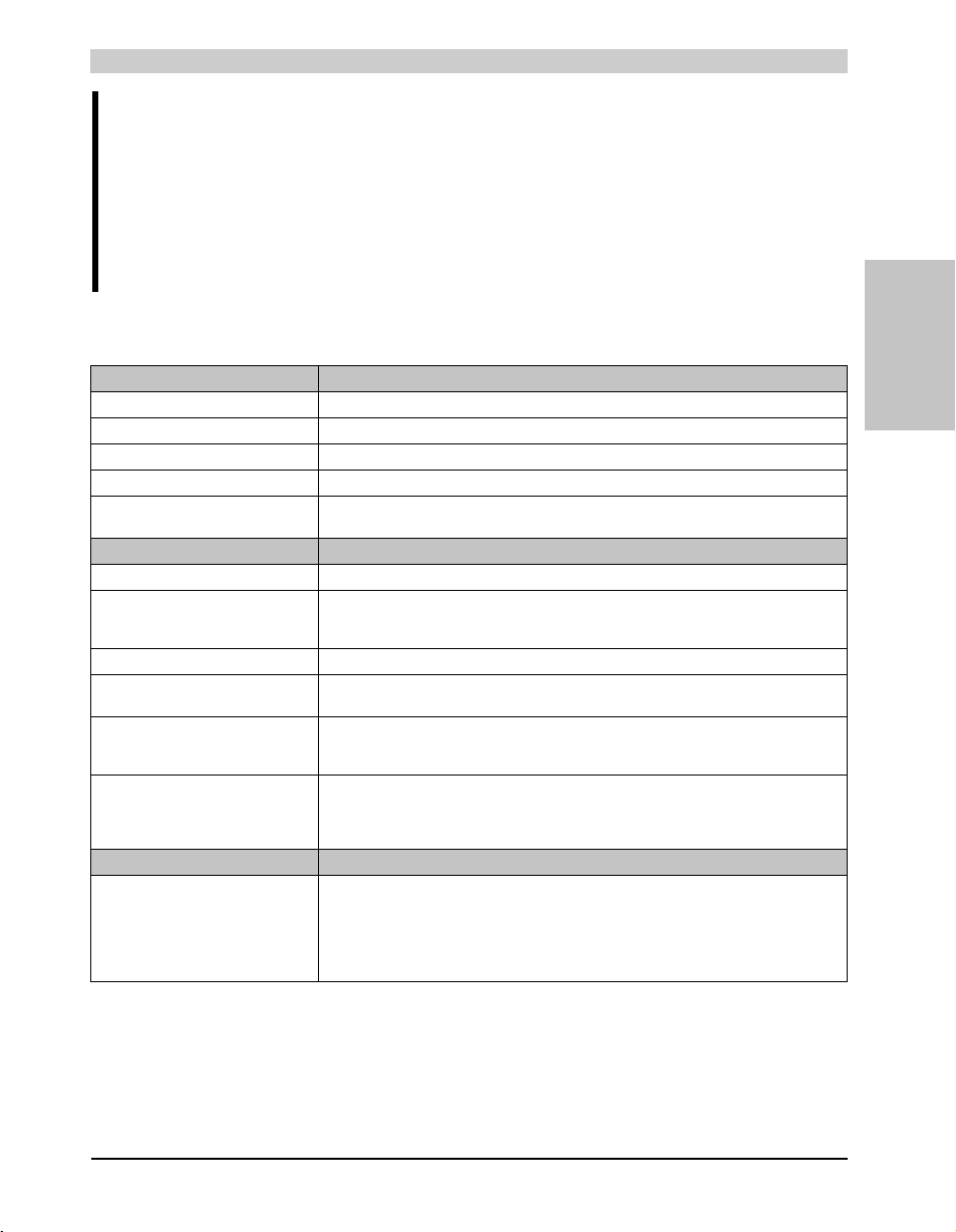
Technical data • Individual components
Warning!
Do not remove the mounting screws from the heat sink, as it is connected to the
processor and chipset by a thermal coupling. If this connection is broken, the
PPC800 must be sent for repair. Removal of the mounting screws, which can be
determined by a broken seal, voids all warranty.
During operation, surface temperatures of the heat sink may reach 70°C (warning
"hot surface").
Technical data
General information 5PC820.1505-00
B&R ID code $AF21
Reset button Yes
Power button Yes
Buzzer Yes
LED
Amount 4 directed outwards via fiber optic lines
Controller
Bootloader BIOS
Processor
Cooling
Method
Main memory Max. 3 GB
Graphics
Controller Component-dependent, see technical data for the 3.2 "CPU boards 945GME", on page 78
Power failure logic
Controller
Buffer time
Battery
Type
Removable
Lifespan
Interfaces
Serial interfaces
Type
Amount
UART
Transfer rate
Connection
Component-dependent, see technical data for the 3.2 "CPU boards 945GME", on page 78
Passive via heat sink and supported with an active fan kit
1)
MTCX
10 ms
Renata 950 mA
Yes, accessible from the outside
2½ years
RS232, modem-capable, not electrically isolated
16550-compatible, 16-byte FIFO
1
Max. 115 kBaud
9-pin D-SUB
Table 43: Technical data - 5PC820.1505-00
Section 2
Technical data
67Panel PC 800 User's Manual V 1.00
Page 68

Technical data • Individual components
Interfaces 5PC820.1505-00
Ethernet
Amount
Transfer rate
Connection
Controller
USB interfaces
Type
Amount
Transfer rate
Connection
Current load
Sound
Inputs
Outputs
CompactFlash slot
Type
Amount
Inserts
PCI slots
Amount 1 or 2 optional
PCIe slots
Amount 1 or 2 optional
PCIec slots
Amount 1, optional with 5AC803.BC01-00
Insert for slide-in compact drive
Amount 1, optional with 5AC803.BC02-00
Insert for slide-in drive 1
Amount Component-dependent (on the expansion and bus unit being used)
Fan insert for fan kit Yes
Add-on UPS slot Yes
Display
Touch screen
Display
Background lighting
2)
Touch screen type
Technology
Controller
Degree of transmission
Type
Diagonal
Colors
Resolution
Contrast
Viewing angle (see page 361)
Horizontal
Vertical
Brightness
Half-brightness time
3)
Low speed (1.5 MBit/s), full speed (12 MBit/s), to high speed (480 MBit/s)
RJ45 twisted pair (10 Base T / 100 Base T)
See page 52 and page 53
Max. 500 mA or 1 A per connection
Direction R = 60° / direction L = 60°
Direction U = 45°/ direction D = 55°
Table 43: Technical data - 5PC820.1505-00 (cont.)
2
10/100/1000 MBit/s
USB 2.0
5
Type A
HDA Sound
Microphone, Line in
Line out
Type I
2
Accu Touch
Analog, resistive
Elo, serial, 12-bit
81±3%
Color TFT
38.10 cm (381 mm)
16 million
XGA, 1024 x 768 pixels
550, 1
250 cd/m²
50,000 hours
68
Panel PC 800 User's Manual V 1.00
Page 69
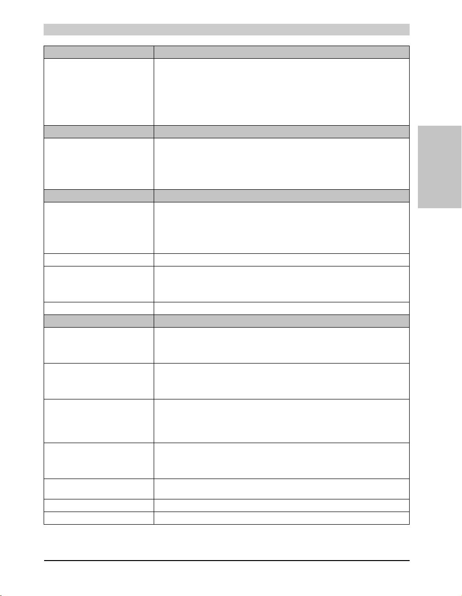
Technical data • Individual components
Display 5PC820.1505-00
Keys
Function keys
Soft keys
Cursor keys
Number block
Other keys
Key lifespan
LED brightness
Electrical characteristics
Power supply
Rated voltage
Rated current
Starting current
Power consumption
Electrical isolation
Mechanical characteristics
Front
Frame
Design
Membrane
Light background
Gasket
Housing Metal
Outer dimensions
Width
Height
Depth
Weight Approx. 5.5 kg (component-dependent)
Environmental characteristics
Ambient temperature
Operation
Storage
Transport
Relative humidity
Operation
Storage
Transport
Vibration
Operation (continuous)
Operation (occasional)
Storage
Transport
Shock
Operation
Storage
Transport
Protection type IP20 back side
Altitude -300 to 3000 m above sea level
Drop height 1 m
Component-dependent, see "Power calculation with 5PC820.1505-00", on page 43
IP65 / NEMA 250 type 4X, dust and sprayed water protection (front side)
Typ. 10 A, max. 50 A for <300µs
Naturally anodized aluminum
Similar to Pantone 427CV
Flat gasket around display front
See also "Dimensions", on page 70
See 2.1.1 "Maximum ambient temperature", on page 38
≤ 40°C: 5 to 90% and > 40°C: < 90%, non-condensing
≤ 40°C: 5 to 90% and > 40°C: < 90%, non-condensing
2 - 8 Hz: 7.5 mm, 8 - 200 Hz: 2 g, 200 - 500 Hz: 4 g
2 - 8 Hz: 7.5 mm, 8 - 200 Hz: 2 g, 200 - 500 Hz: 4 g
10 to 85%, non-condensing
2 - 9 Hz: 1.75 mm, 9 - 150 Hz: 0.5 g
2 - 9 Hz: 3.5 mm, 9 - 150 Hz: 1 g
Table 43: Technical data - 5PC820.1505-00 (cont.)
-
24 VDC ±25%
6 A
Yes
Gray
Polyester
435 mm
330 mm
Component-dependent
-20 to +60°C
-20 to +60°C
15 g, 11 ms
30 g, 15 ms
30 g, 15 ms
Section 2
Technical data
69Panel PC 800 User's Manual V 1.00
Page 70
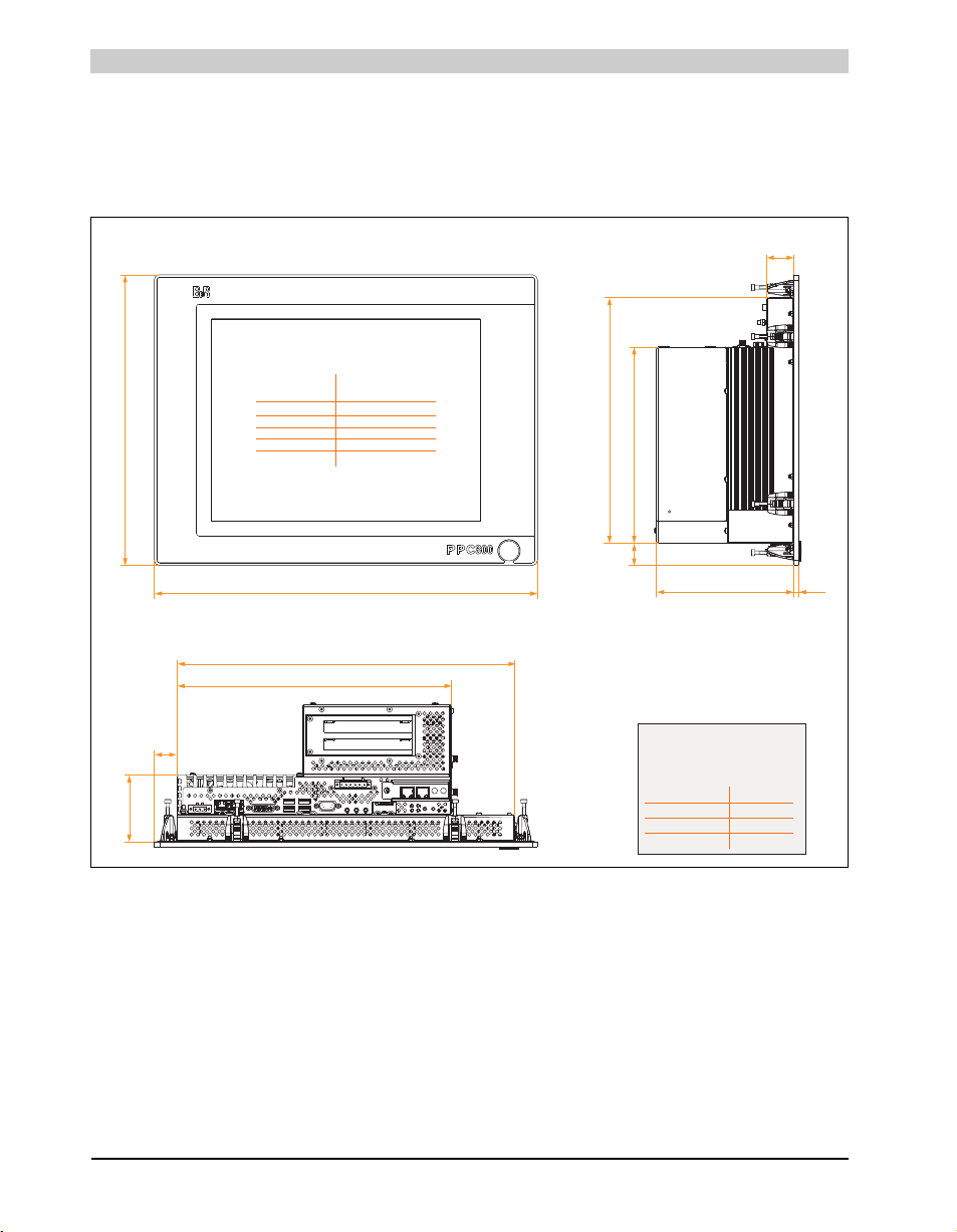
Technical data • Individual components
up to 6 mm
over 6 to 30 mm
over 30 to 120 mm
over 120 to 400
over 400 to 1000
± 0.1 mm
± 0.2 mm
± 0.3 mm
± 0.5 mm
± 0.8 mm
Nominal General tolerance acc.
measurement area to DIN ISO 2768 medium
311
383
26
76
435
26
330
222
278
“A”
Information:
The value depends on the
expansion being used!
A
5AC803.SX01-00
136
without expansion
81.7
5.7
5AC803.SX02-00
156
Model number
Values in mm
The screw heads with a height of 2.5 mm must
also be accounted for in the depth measurement.
31
1) Maintenance controller extended.
2) Touch screen drivers can be downloaded from the download area on the B&R homepage (www.br-automation.com).
3) At 25°C ambient temperature. Reducing the brightness by 50% can result in an approximate 50% increase of the half-brightness time.
Dimensions
Figure 14: Dimensions - 5PC820.1505-00
70
Panel PC 800 User's Manual V 1.00
Page 71
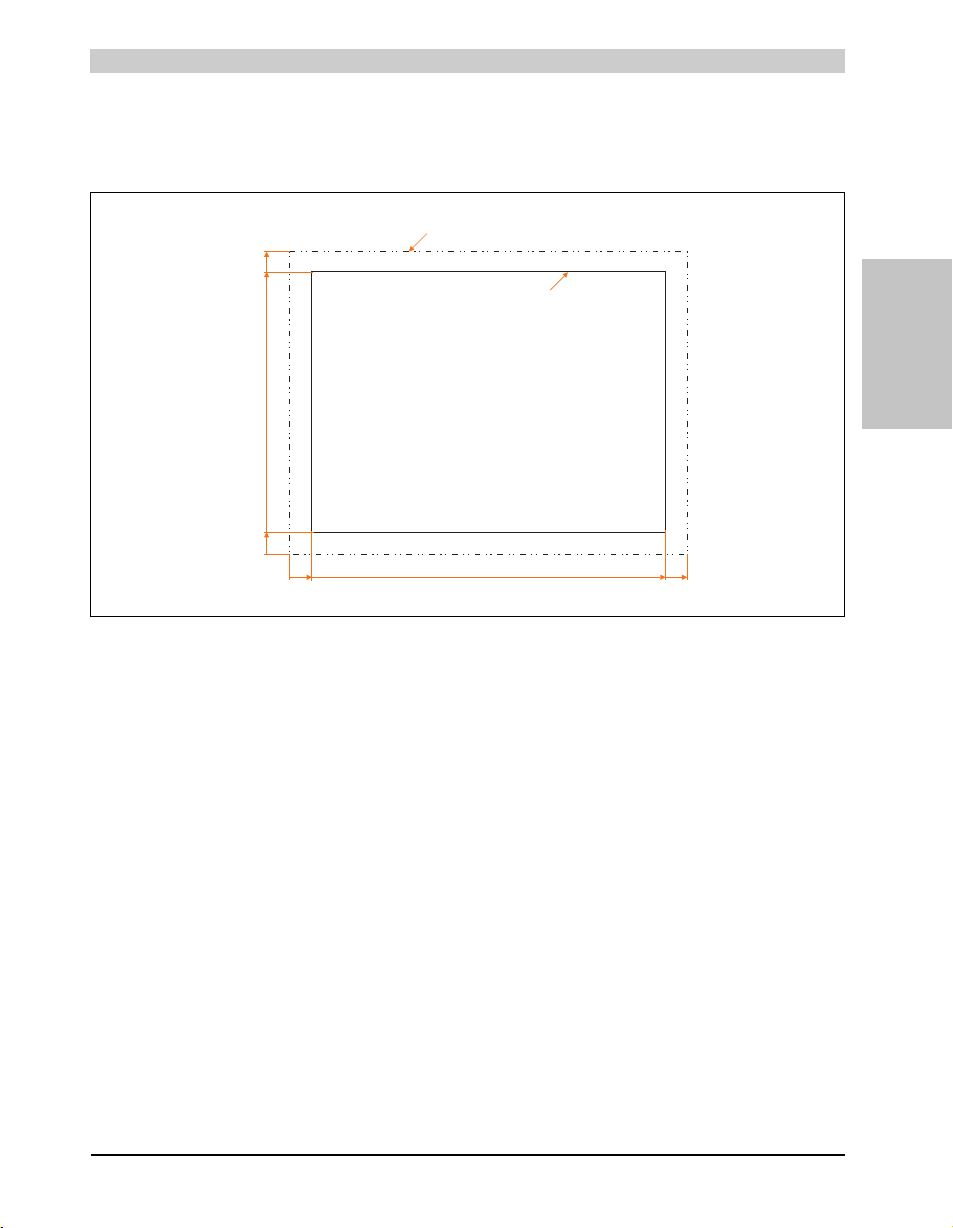
Technical data • Individual components
0
Cut-out dimensions 415 ±0.5 mm x 312 ±0.5 mm suitable for
5PC820.1505-00
Cut-out
Outer contours (Panel PC 800)
10
435
425
0
330
9
321
Cutout installation
The Panel PC 800 with preassembled mounting blocks is installed e.g. in a housing cutout. A
cutout that corresponds to the following drawing must be made.
Figure 15: Cutout installation - 5PC820.1505-00
Section 2
Technical data
71Panel PC 800 User's Manual V 1.00
Page 72
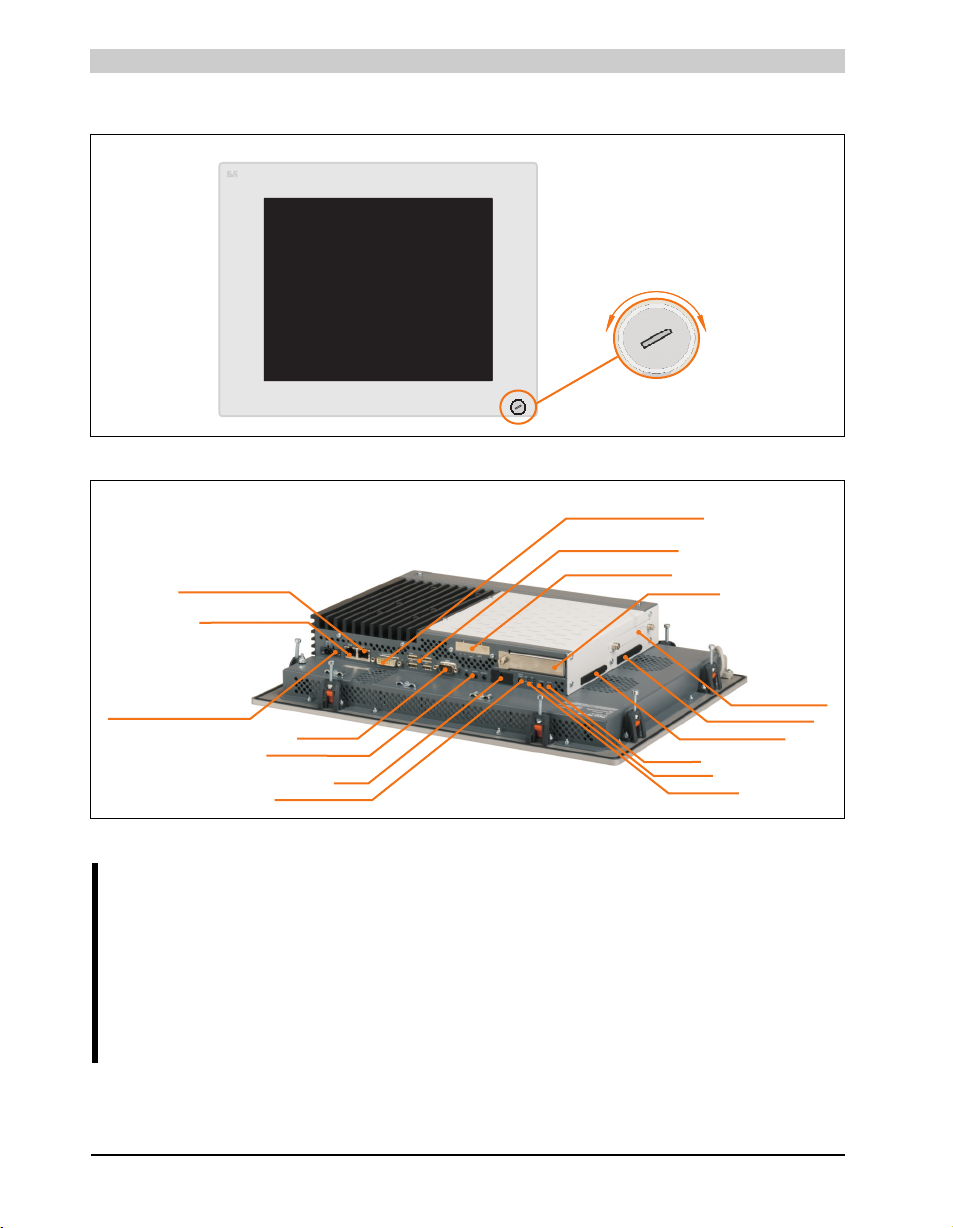
Technical data • Individual components
PANELPC
O
p
e
n
C
l
o
s
e
USB connection on front
PCIec Card slot
Add-on UPS slot
USB 1, USB2, USB3, USB4
Ethernet 2 (10/100/1000)
(ETH2)
HDA Sound
MIC, Line IN, Line OUT
Reset button
COM1 RS232
Supply voltage + 24 VDC
Battery
LED for: Power,
Link1, Run, HDD
Power button
Ethernet 1
(ETH1)
(10/100/1000)
Monitor/Panel
SDL (Smart Display Link) / DVI
CMOS profile switch
CompactFlash slot CF1
CompactFlash slot CF2
Slide-in compact slot
3.1.2 Panel PC 5PC820.1906-00
Figure 16: Front view - 5PC820.1906-00
Warning!
Do not remove the mounting screws from the heat sink, as it is connected to the
processor and chipset by a thermal coupling. If this connection is broken, the
PPC800 must be sent for repair. Removal of the mounting screws, which can be
determined by a broken seal, voids all warranty.
During operation, surface temperatures of the heat sink may reach 70°C (warning
"hot surface").
72
Figure 17: Rear view - 5PC820.1906-00
Panel PC 800 User's Manual V 1.00
Page 73
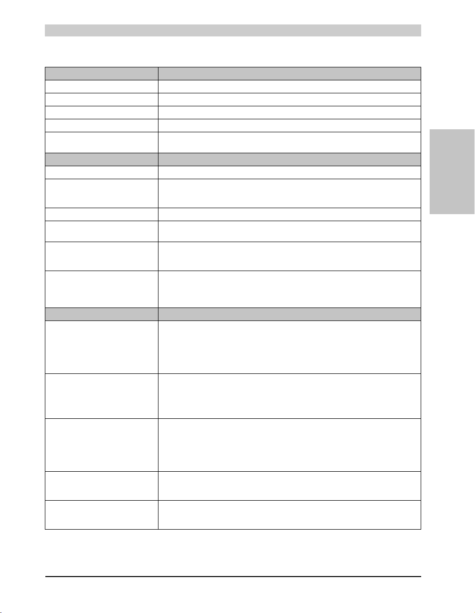
Technical data • Individual components
Technical data
General information 5PC820.1906-00
B&R ID code $AF22
Reset button Yes
Power button Yes
Buzzer Yes
LED
Amount 4 directed outwards via fiber optic lines
Controller
Bootloader BIOS
Processor
Cooling
Method
Main memory Max. 3 GB
Graphics
Controller Component-dependent, see technical data for the 3.2 "CPU boards 945GME", on page 78
Power failure logic
Controller
Buffer time
Battery
Type
Removable
Lifespan
Interfaces
Serial interfaces
Type
Amount
UART
Transfer rate
Connection
Ethernet
Amount
Transfer rate
Connection
Controller
USB interfaces
Type
Amount
Transfer rate
Connection
Current load
Sound
Inputs
Outputs
CompactFlash slot
Type
Amount
Component-dependent, see technical data for the 3.2 "CPU boards 945GME", on page 78
Passive via heat sink and supported with an active fan kit
1)
MTCX
10 ms
Renata 950 mA
Yes, accessible from the outside
2½ years
RS232, modem-capable, not electrically isolated
16550-compatible, 16-byte FIFO
RJ45 twisted pair (10 Base T / 100 Base T)
See page 52 and page 53
Low speed (1.5 MBit/s), full speed (12 MBit/s), to high speed (480 MBit/s)
Max. 500 mA or 1 A per connection
1
Max. 115 kBaud
9-pin D-SUB
2
10/100/1000 MBit/s
USB 2.0
5
Type A
HDA Sound
Microphone, Line in
Line out
Type I
2
Table 44: Technical data - 5PC820.1906-00
Section 2
Technical data
73Panel PC 800 User's Manual V 1.00
Page 74

Technical data • Individual components
Inserts 5PC820.1906-00
PCI slots
Amount 1 or 2 optional
PCIe slots
Amount 1 or 2 optional
PCIec slots
Amount 1, optional with 5AC803.BC01-00
Insert for slide-in compact drive
Amount 1, optional with 5AC803.BC02-00
Insert for slide-in drive 1
Amount Component-dependent (on the expansion and bus unit being used)
Fan insert for fan kit Yes
Add-on UPS slot Yes
Display
Touch screen
Display
Background lighting
Keys
Electrical characteristics
Power supply
2)
Touch screen type
Technology
Controller
Degree of transmission
Type
Diagonal
Colors
Resolution
Contrast
Viewing angle (see page 361)
Horizontal
Vertical
Brightness
Half-brightness time
Function keys
Soft keys
Cursor keys
Number block
Other keys
Key lifespan
LED brightness
Rated voltage
Rated current
Starting current
Power consumption
Electrical isolation
3)
Accu Touch
Analog, resistive
Elo, serial, 12-bit
81% ±3
Color TFT
19 inch (480 mm)
16,777,216 colors
SXGA, 1280 x 1024 pixels
900, 1
Direction R / direction L = 85°
Direction U / direction D = 85°
300 cd/m²
50,000 hours
-
24 VDC ±25%
Component-dependent, see "Power calculation with 5PC820.1906-00", on page 44
Typ. 10 A, max. 50 A for <300µs
6 A
Yes
Table 44: Technical data - 5PC820.1906-00 (cont.)
74
Panel PC 800 User's Manual V 1.00
Page 75
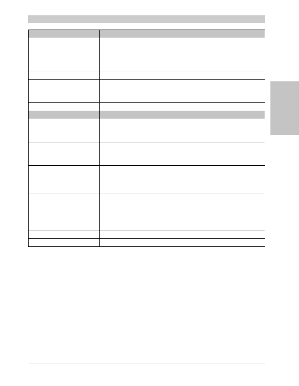
Technical data • Individual components
Mechanical characteristics 5PC820.1906-00
Front
Frame
Design
Membrane
Light background
Gasket
Housing Metal
Outer dimensions
Width
Height
Depth
Weight Approx. 10 kg (component-dependent)
Environmental characteristics
Ambient temperature
Operation
Storage
Transport
Relative humidity
Operation
Storage
Transport
Vibration
Operation (continuous)
Operation (occasional)
Storage
Transport
Shock
Operation
Storage
Transport
Protection type IP20 back side
Altitude -300 to 3000 m above sea level
Drop height 1 m
See 2.1.1 "Maximum ambient temperature", on page 38
≤ 50°C: 10 to 85% and > 50°C: max. 80%, non-condensing
≤ 40°C: 5 to 90% and > 40°C: < 90%, non-condensing
≤ 40°C: 5 to 90% and > 40°C: < 90%, non-condensing
IP65 / NEMA 250 type 4X, dust and sprayed water protection (front side)
Table 44: Technical data - 5PC820.1906-00 (cont.)
Naturally anodized aluminum
Flat gasket around display front
See also "Dimensions", on page 76
2 - 9 Hz: 1.75 mm, 9 - 150 Hz: 0.5 g
2 - 9 Hz: 3.5 mm, 9 - 150 Hz: 1 g
2 - 8 Hz: 7.5 mm, 8 - 200 Hz: 2 g, 200 - 500 Hz: 4 g
2 - 8 Hz: 7.5 mm, 8 - 200 Hz: 2 g, 200 - 500 Hz: 4 g
Gray
Polyester
Similar to Pantone 427CV
527 mm
421 mm
Component-dependent
-20 to +60°C
-20 to +60°C
15 g, 11 ms
30 g, 15 ms
30 g, 15 ms
Section 2
Technical data
1) Maintenance controller extended.
2) Touch screen drivers can be downloaded from the download area on the B&R homepage (www.br-automation.com).
3) At 25°C ambient temperature. Reducing the brightness by 50% can result in an approximate 50% increase of the half-brightness time.
75Panel PC 800 User's Manual V 1.00
Page 76
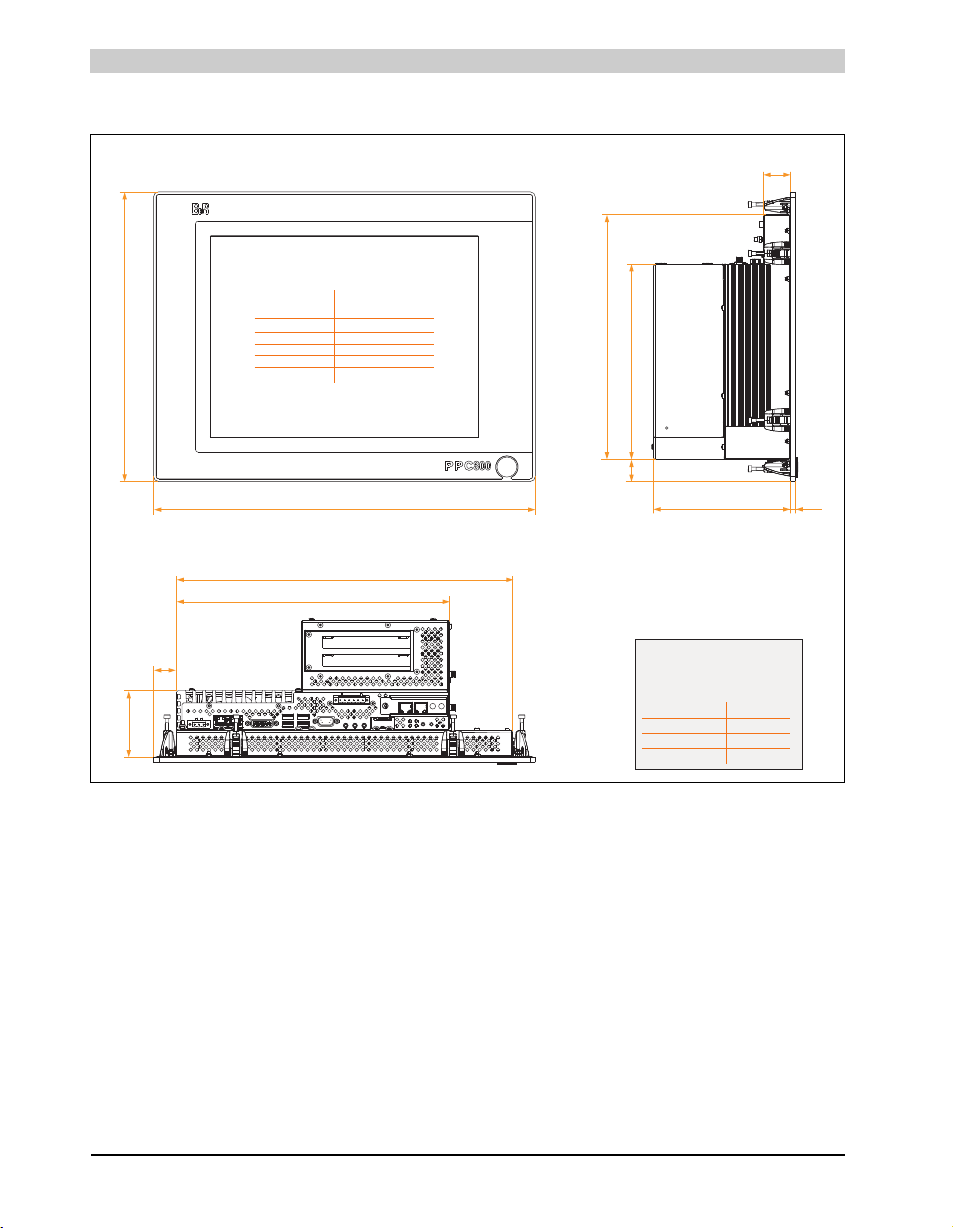
Technical data • Individual components
up to 6 mm
over 6 to 30 mm
over 30 to 120 mm
over 120 to 400
over 400 to 1000
± 0.1 mm
± 0.2 mm
± 0.3 mm
± 0.5 mm
± 0.8 mm
Nominal General tolerance acc.
measurement range to DIN ISO 2768 medium
311
475
76
527
26
421
222
369
“A”
5.7
26
Information:
The value depends on the
expansion being used!
A
5AC803.SX01-00
136
without expansion
81.7
5AC803.SX02-00
156
Model numbers
Values in mm
The screw heads with a height of 2.5 mm must
also be accounted for in the depth measurement.
31
Dimensions
76
Figure 18: Dimensions - 5PC820.1906-00
Panel PC 800 User's Manual V 1.00
Page 77
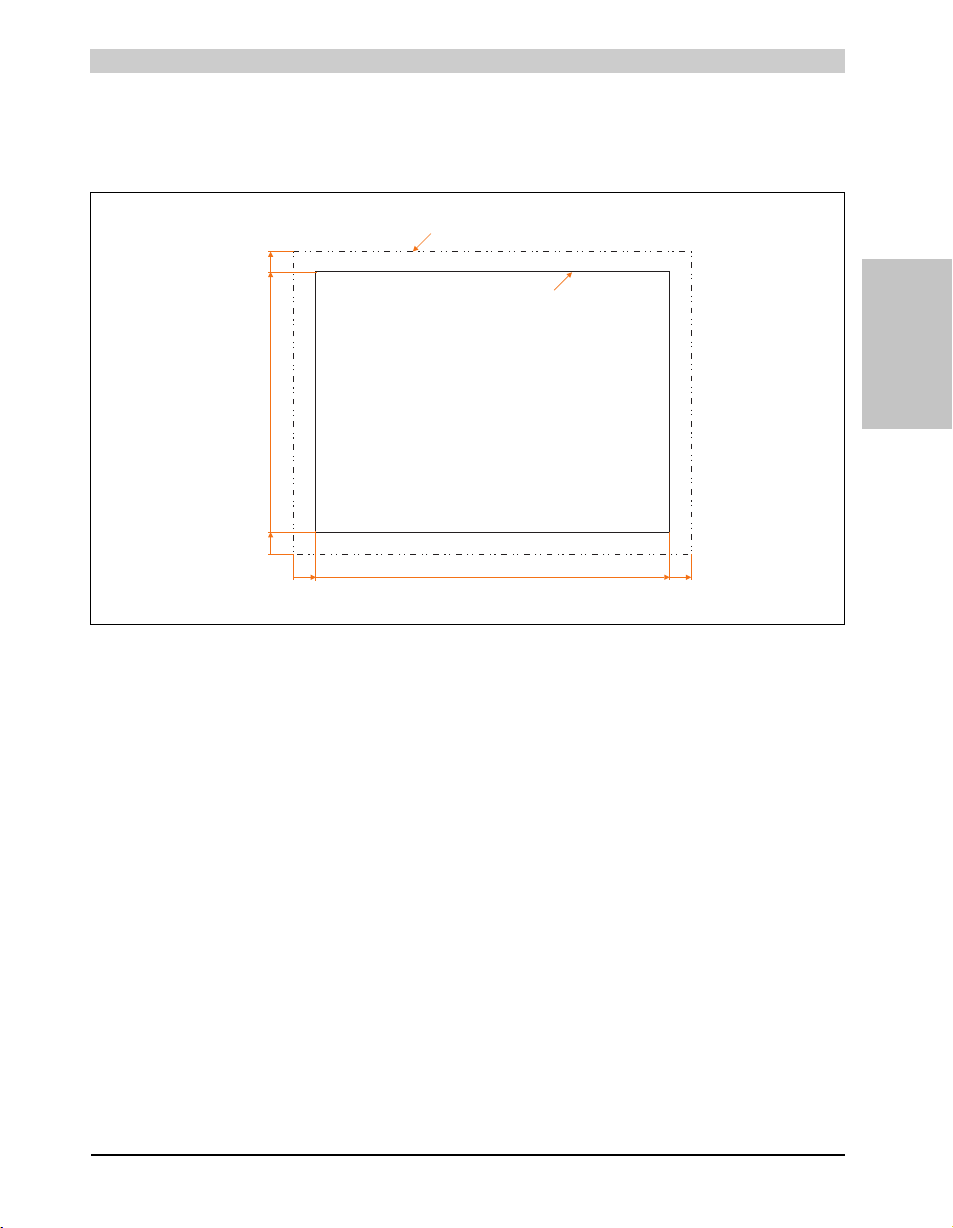
Technical data • Individual components
Cut-out dimensions 510 ±0.5 mm x 404 ±0.5 mm suitable for
5PC820.1906-00
Cut-out
Outer contours (Panel PC 800)
0
421
8.5
412.5
0
8.5
527
518.5
Cutout installation
The Panel PC 800 with preassembled mounting blocks is installed e.g. in a housing cutout. A
cutout that corresponds to the following drawing must be made.
Section 2
Technical data
Figure 19: Cutout installation - 5PC820.1906-00
77Panel PC 800 User's Manual V 1.00
Page 78
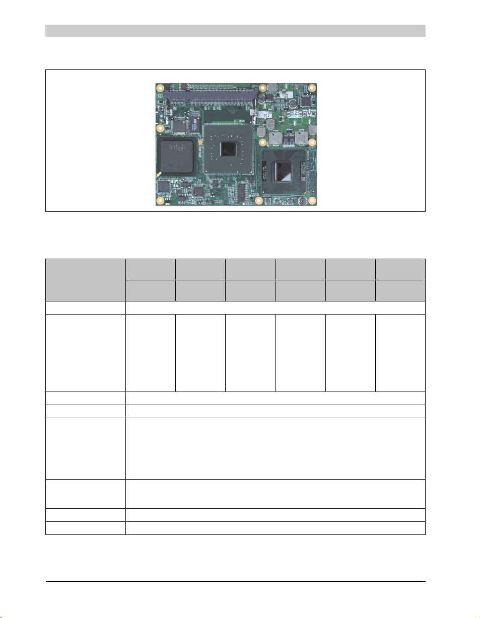
Technical data • Individual components
3.2 CPU boards 945GME
Figure 20: CPU board
3.2.1 Technical data
Features 5PC800.B945-005PC800.B945-015PC800.B945-025PC800.B945-035PC800.B945-045PC800.B945-
5PC800.B945-105PC800.B945-115PC800.B945-125PC800.B945-135PC800.B945-
Boot loader / Operating sys. embedded AMI BIOS (for a description, see Chapter 4 "Software", section "BIOS options", on page 167)
Processor
Type
Name
Clock frequency
Architectures
L1 cache
L2 cache
Front side bus - FSB
Chipset Intel® 945GME / Intel 82801 GMH (ICH7M-DH)
Memory SO-DIMM DDR2 667/PC5300, max. 3 GByte
Graphics
Controller
Memory
Color depth
Resolution
RGB
DVI
Real-time clock (RTC)
Battery-buffered
Accuracy
Mass memory management 2x SATA, 1x IDE
Power management ACPI 2.0, S3 Support (suspend to RAM)
Intel® Core™
Duo
L2400
1.66 GHz
65 nm
32 KB
2 MB
667 MHz
Intel® Core™2
Duo
L7400
1.5 GHz
65 nm
32 KB
4 MB
667 MHz
400 MHz RAMDAC, up to 2048 x 1536 @75 Hz (QXGA) including 1920 x 1080 @ 85 Hz (HDTV)
Intel® Core™2
Duo
U7500
1.06 GHz
65 nm
32 KB
2 MB
533 MHz
Intel® Graphics Media Accelerator 950
Up to 224 MB (reserved from main memory)
2x Intel compliant SDVO port, 1920 x 1080
At 25°C typ. 12 ppm (1 second)
Intel® Celeron®
Max. 32-bit
Yes
M
423
1.06 GHz
65 nm
32 KB
1 MB
533 MHz
1)
per day
14
Intel® Core™2
Duo
T7400
2.16 GHz
65 nm
32 KB
4 MB
667 MHz
05
Intel® Atom™
N270
1.66 GHz
45 nm
24 KB
512 kB
533 MHz
Table 45: Technical data - CPU boards
1) At max. specified ambient temperature: typ. 58 ppm (5 seconds) - worst-case 220 ppm (19 seconds).
78
Panel PC 800 User's Manual V 1.00
Page 79
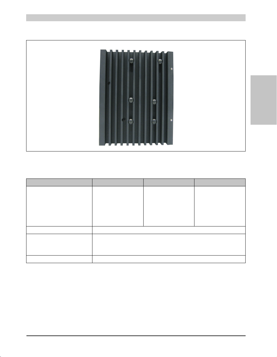
Technical data • Individual components
3.3 Heat sink
Figure 21: Heat sink
3.3.1 Technical data
Mechanical characteristics 5AC803.HS00-00 5AC803.HS00-01 5AC803.HS00-02
Ideal for CPU boards 5PC800.B945-00
Item Aluminum, black-coated with copper heat pipes
Outer dimensions
Width
Height
Depth
Weight Approx. 1.2 kg
5PC800.B945-01
5PC800.B945-02
5PC800.B945-03
5PC800.B945-10
5PC800.B945-11
5PC800.B945-12
5PC800.B945-13
5PC800.B945-04
5PC800.B945-14
143 mm
183.5 mm
60 mm
Table 46: Technical data - Heat sink
5PC800.B945-05
Section 2
Technical data
79Panel PC 800 User's Manual V 1.00
Page 80
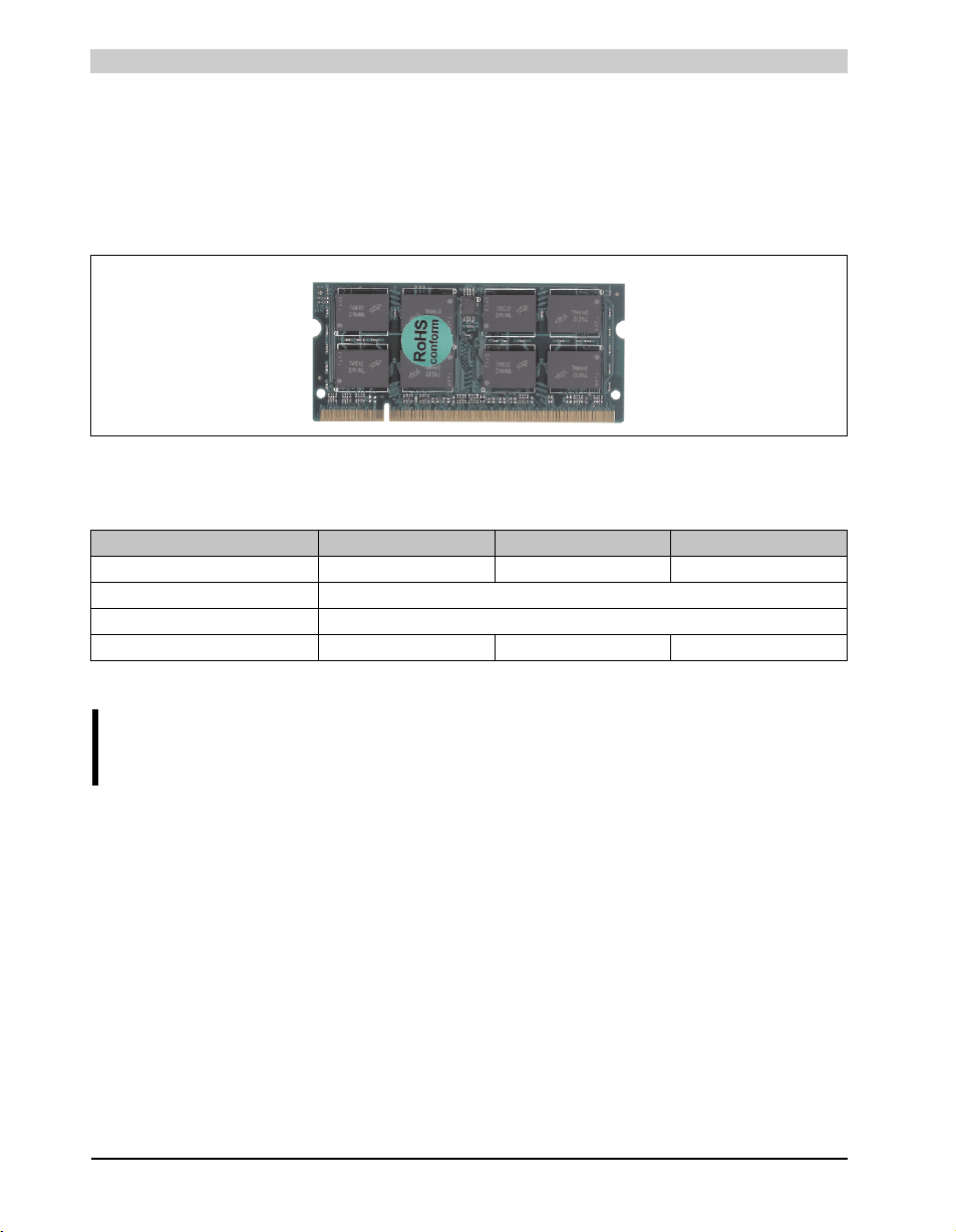
Technical data • Individual components
3.4 Main memory
The CPU boards offer room for two main memory modules. Dual-Channel memory technology
is supported when two modules of the same size (e.g. 1 GB) are plugged in. This technology is
not supported when two modules of different sizes (e.g. 1 GB and 2 GB) are plugged in.
When two 2 GB modules are plugged in, only 3 GB of main memory can be used.
Figure 22: Main memory
3.4.1 Technical data
Features 5MMDDR.0512-01 5MMDDR.1024-01 5MMDDR.2048-01
Quantity 512 MB 1 GB 2 GB
Type DDR2 SDRAM / PC2-5300
Construction 200 Pin SO-DIMM
Organization 64M x 64-bit 128M x 64-bit 256M x 64-bit
Table 47: Technical data - Main memory
Information:
A main memory module can only be replaced at the B&R plant.
80
Panel PC 800 User's Manual V 1.00
Page 81
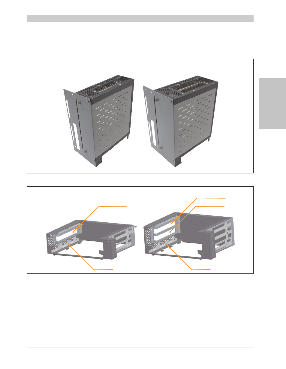
Technical data • Individual components
1 slot expansion 2 slot expansion
Slide-in slot 1
PCI/PCIe card slot 1
PCI/PCIe card slot 1
PCI/PCIe card slot 2
Slide-in slot 1
3.5 Expansion
The PPC800 expansion is an expandable extension for mounting up to 2 PCI / PCIe cards and
a slide-in drive.
Figure 23: 1 slot and 2 slot expansion
Section 2
Technical data
Figure 24: Expansion description
81Panel PC 800 User's Manual V 1.00
Page 82

Technical data • Individual components
± 0,1 mm
± 0,2 mm
± 0,3 mm
± 0,5 mm
± 0,8 mm
General tolerance acc.
to DIN ISO 2768 medium
up to 6 mm
over 6 to 30 mm
over 30 to 120 mm
over 120 to 400
over 400 to 1000
Nominal
measurement area
222
60
167
3.5.1 Technical data
Inserts 5AC803.SX01-00 5AC803.SX02-00
PCI/PCIe slots
Amount 1 2
Slide-in drive
Amount 1 1
Mechanical characteristics
Dimensions
Width
Height
Depth
167mm
222 mm
60 mm
167mm
222 mm
80 mm
Weight Approx. 1 kg Approx. 1kg
Table 48: Technical data - Expansion
3.5.2 Dimensions - 5PC803.SX01-00
82
Figure 25: Dimensions - Expansion 5PC803.SX01-00
Panel PC 800 User's Manual V 1.00
Page 83
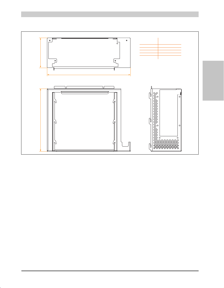
3.5.3 Dimensions - 5PC803.SX02-00
± 0,1 mm
± 0,2 mm
± 0,3 mm
± 0,5 mm
± 0,8 mm
General tolerance acc.
to DIN ISO 2768 medium
up to 6 mm
over 6 to 30 mm
over 30 to 120 mm
over 120 to 400
over 400 to 1000
Nominal
measurement area
222
80
167
Technical data • Individual components
Section 2
Technical data
Figure 26: Dimensions - Expansion 5PC803.SX02-00
83Panel PC 800 User's Manual V 1.00
Page 84
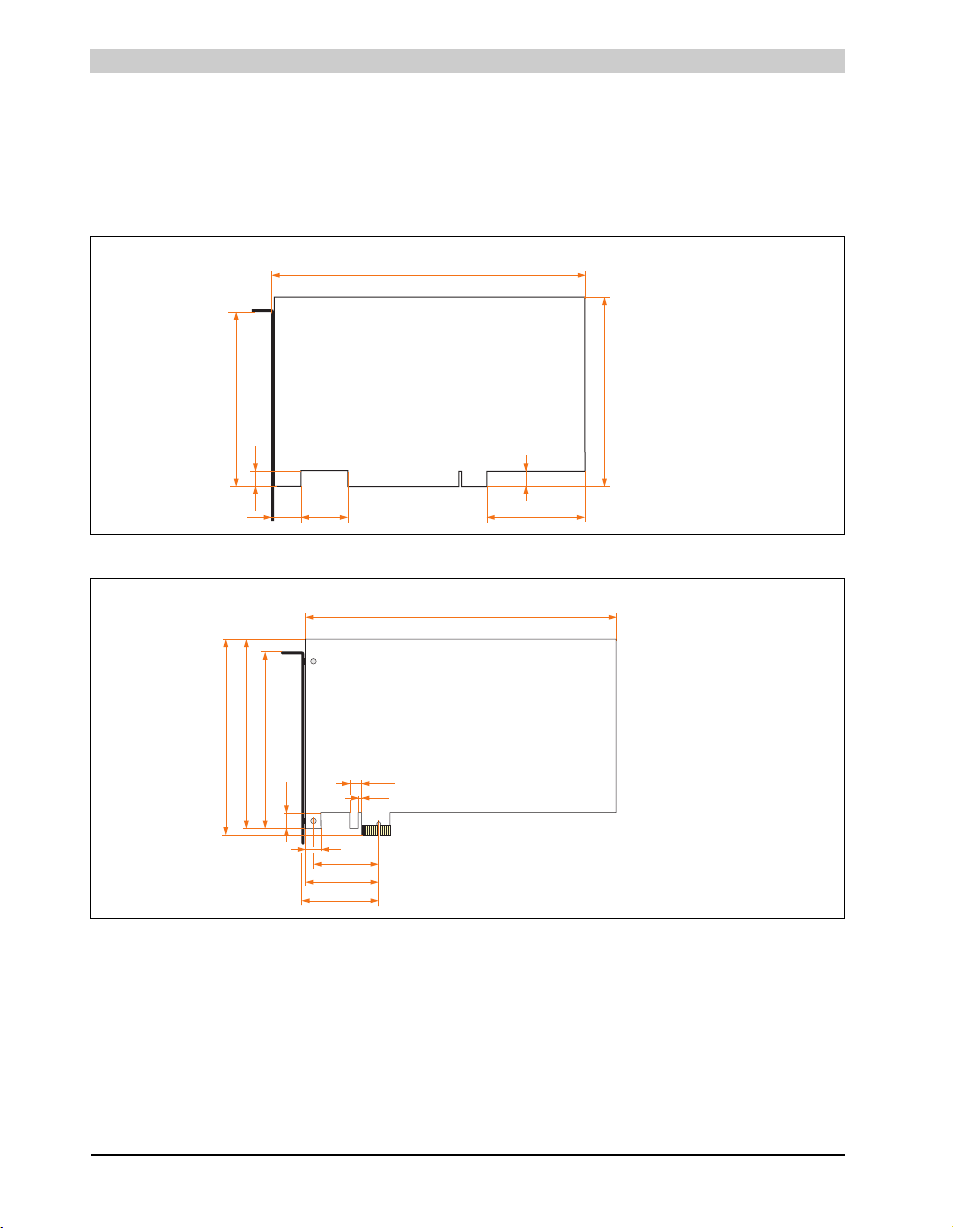
Technical data • Individual components
177.7
106.7
9
25.8
9
5517.4
100.5
All values in mm
167.65
8.25
106.65
15
49.65
57.15
3.65
11.65
111.15
59.05
100.36
All values in mm
3.5.4 Slot for bus units
Card slot (PCI / PCIe)
Standard PCI 2.2 half-size cards or PCI Express (PCIe) half-size cards can be plugged in
depending on the type of bus unit. They cannot exceed the following dimensions.
Figure 27: Dimensions - Standard half-size PCI card
84
Figure 28: Dimensions - Standard half-size PCIe card
Panel PC 800 User's Manual V 1.00
Page 85
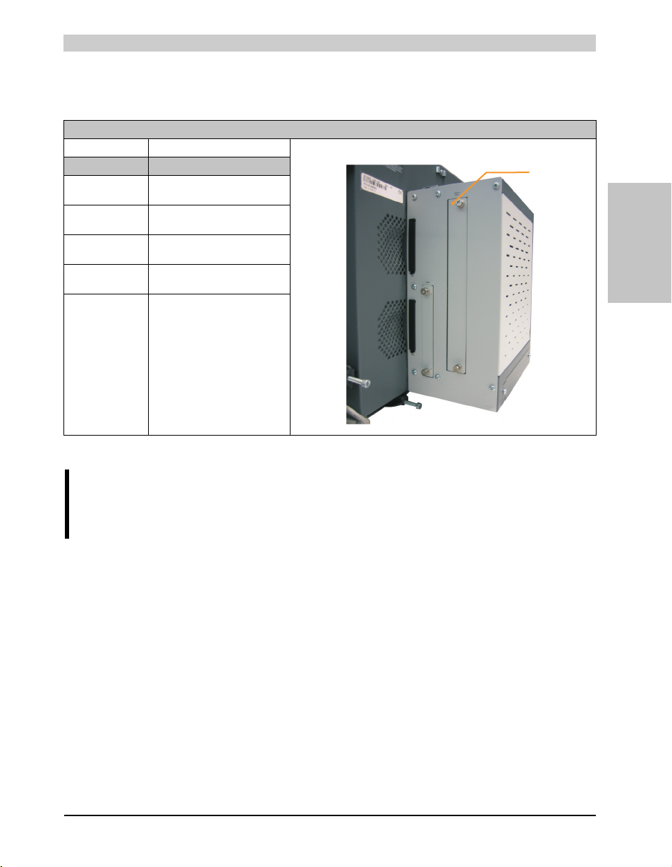
Technical data • Individual components
Slide-in slot 1
3.5.5 Slide-in slot 1
The slide-in slot 1 is internally connected with the chipset via SATA I and USB.
Slide-in slot 1
Connection SATA I and USB
Accessories Short d escription
5AC801.ADAS-00 APC810 and PPC800 slide-in
compact adapter
5AC801.HDDS-00 APC810 and PPC800 slide-in HDD
EE25
5AC801.DVRS-00 APC810 and PPC800 slide-in DVD-
R/RW
5AC801.DVDS-00 APC810 and PPC800 slide-in DVD
ROM
Table 49: Slide-in slot 1
Section 2
Technical data
Information:
The SATA I interface allows data carriers to be exchanged during operation (hotplug). To utilize this capability, it must be supported by the operating system.
85Panel PC 800 User's Manual V 1.00
Page 86
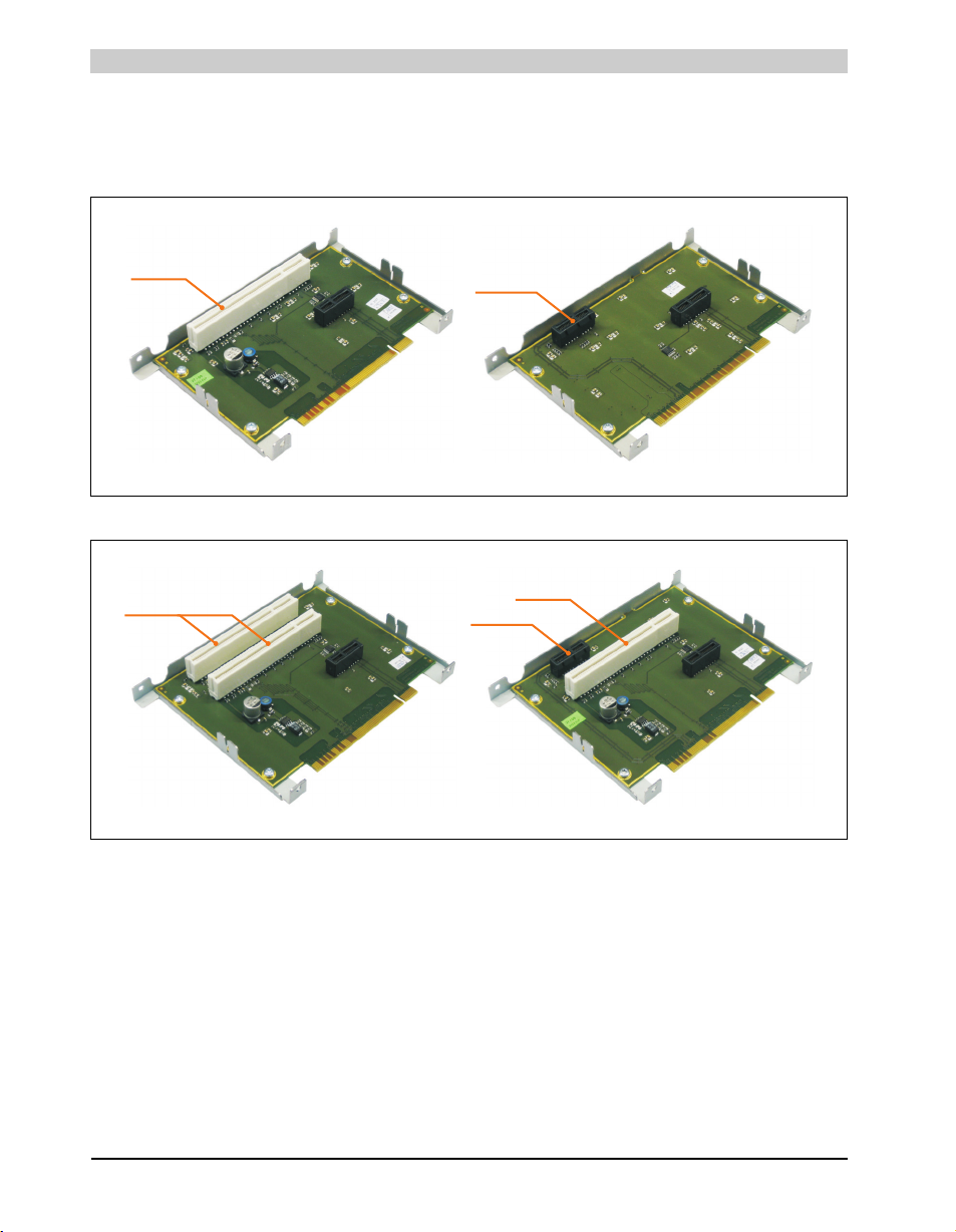
Technical data • Individual components
5PC803.BX01-015PC803.BX01-00
1 PCI slot
1 PCIe slot
5PC803.BX02-015PC803.BX02-00
1 PCI slot
1 PCIe slot
1 PCI slot
3.6 Bus units
The bus units are compatible with the expansions in 1 or 2 PCI slot sizes, available with PCI
and/or PCI Express support.
Figure 29: 1 slot bus units
86
Figure 30: 2 slot bus units
Panel PC 800 User's Manual V 1.00
Page 87
Technical data • Individual components
3.6.1 Technical data
Inserts 5AC803.BX01-00 5AC803.BX01-01 5AC803.BX02-00 5AC803.BX02-01
PCI slot
Amount
Default
PCI bus type
Bus speed
PCI Express
Amount
Default
Bus speed
1
2.2
32-bit
33 MHz
-
-
1
1.0a
x1 (250 MB/s)
Table 50: Technical data - Bus units
2
2.2
32-bit
33 MHz
-
1
2.2
32-bit
33 MHz
1
1.0a
x1 (250 MB/s)
Section 2
Technical data
87Panel PC 800 User's Manual V 1.00
Page 88
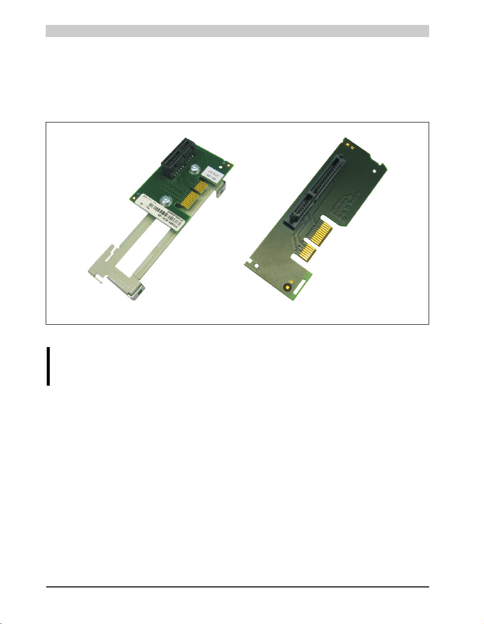
Technical data • Individual components
5PC803.BC01-00 5PC803.BC02-00
3.7 Option
The option 5AC803.BC01-00 enables a PCIec plug-in card to be connected to the system unit.
If the option 5AC803.BC02-00 is selected, then a slide-in compact drive can be operated in the
system unit. It is also possible to select both options so that a PCIec plug-in card and a slide-in
compact drive can be operated in the PC 800.
Figure 31: Options
Information:
Options are only available factory-installed.
88
Panel PC 800 User's Manual V 1.00
Page 89
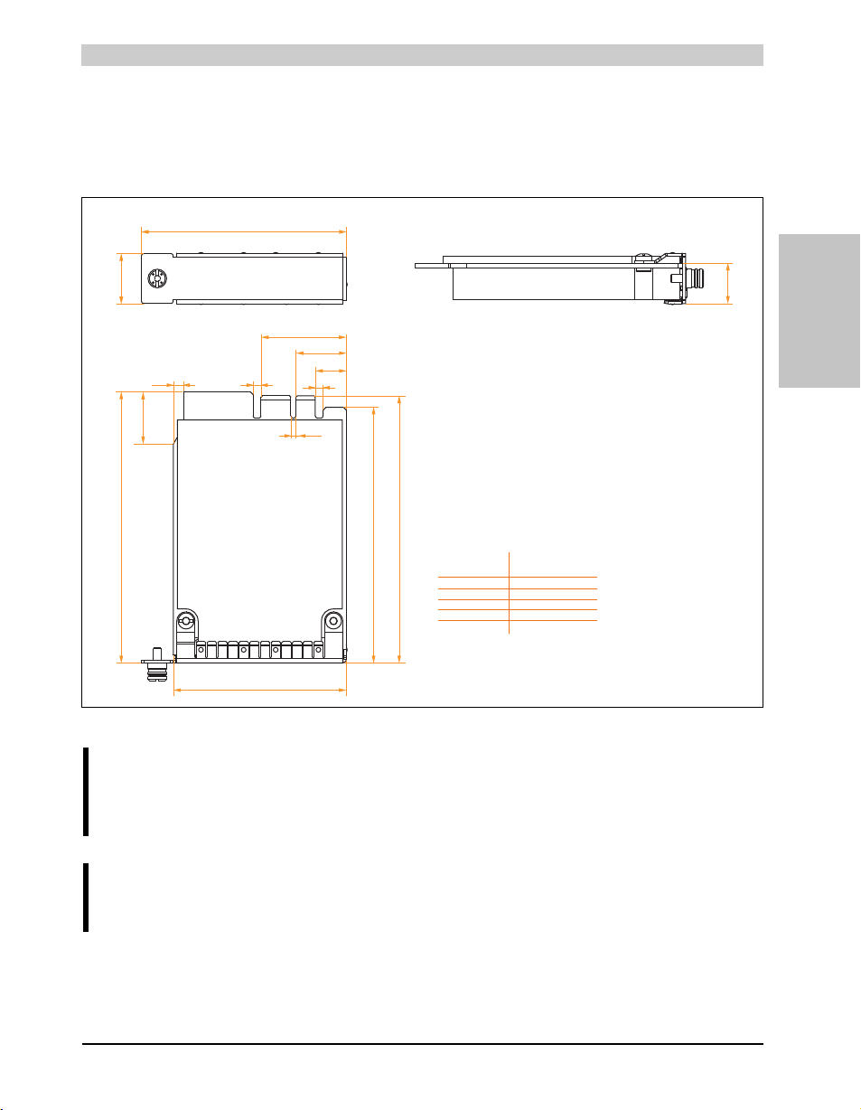
Technical data • Individual components
± 0,1 mm
± 0,2 mm
± 0,3 mm
± 0,5 mm
± 0,8 mm
General tolerance acc.
to DIN ISO 2768 medium
up to 6 mm
over 6 to 30 mm
over 30 to 120 mm
over 120 to 400
over 400 to 1000
Nominal
measurement area
100
95.7
101.5
19
11.65
15.2
64.9
All values in mm.
76.9
19.8
3
31.95
3
1.9
3.8
19.6
3.8 Plug-in cards
The PCIec plug-in cards are equipped with a sensor that monitors the card's temperature. This
value is read out in the BIOS (menu item: Advanced - Baseboard/Panel Features - Baseboard
Monitor on page 207) and in the ADI.
Section 2
Technical data
Figure 32: Dimensions - PCIec cards
Information:
Only B&R PCIec cards that were specially designed for the Automation PC 820 and
Panel PC 800 can be used.
Information:
The option 5AC803.BC01-00 is required for the use of PCIec plug-in cards.
89Panel PC 800 User's Manual V 1.00
Page 90
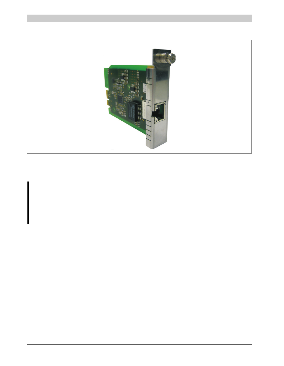
Technical data • Individual components
3.8.1 Ethernet Card 10/100/1000 - 5ACPCC.ETH0-00
Figure 33: Ethernet card 10/100/1000 - 5ACPCC.ETH0-00
Technical data
Information:
The following characteristics, features, and limit values only apply to this individual
component and can deviate from those specified for the entire device. For the entire
device in which this individual component is used, refer to the data given
specifically for the entire device.
90
Panel PC 800 User's Manual V 1.00
Page 91
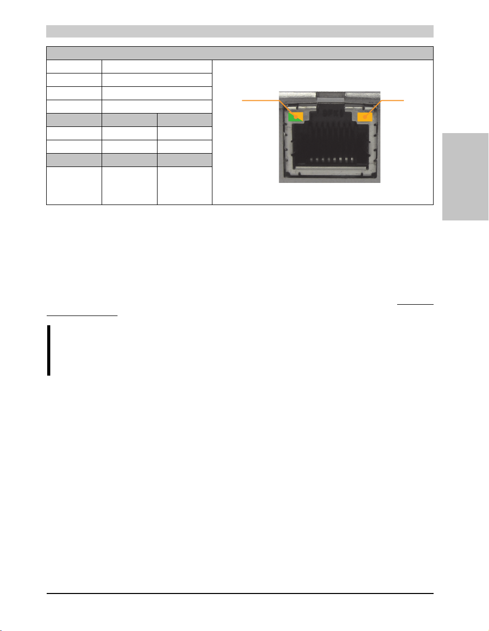
Technical data • Individual components
Speed LED
(green / orange)
Link LED
(orange)
Ethernet card 1 connection
Controller Intel 82574
Cabling S/STP (Cat5e)
Transfer rate 10/100/1000 MBit/s
Cable length max. 100 m (min. Cat5e)
Speed LED On Off
Green 100 Mbit/s 10 Mbit/s
Orange 1000 Mbit/s -
Link LED On Off
Orange Link
(Ethernet network
connection
available)
1)
2)
Activity (blinking)
(data being
transferred)
Table 51: Technical data - Ethernet card 10/100/1000 - 5ACPCC.ETH0-00
1) Change-over takes place automatically.
2) The 10 MBit/s transfer speed / connection is only present if the IF slot Link LED is simultaneously active.
Driver support
A special driver is necessary for operating the Intel Ethernet controller 82574. The necessary
drivers can be downloaded from the download area on the B&R homepage (www.br-
automation.com).
Section 2
Technical data
Information:
Required drivers can only be downloaded from the B&R homepage, not from
manufacturers' pages.
91Panel PC 800 User's Manual V 1.00
Page 92
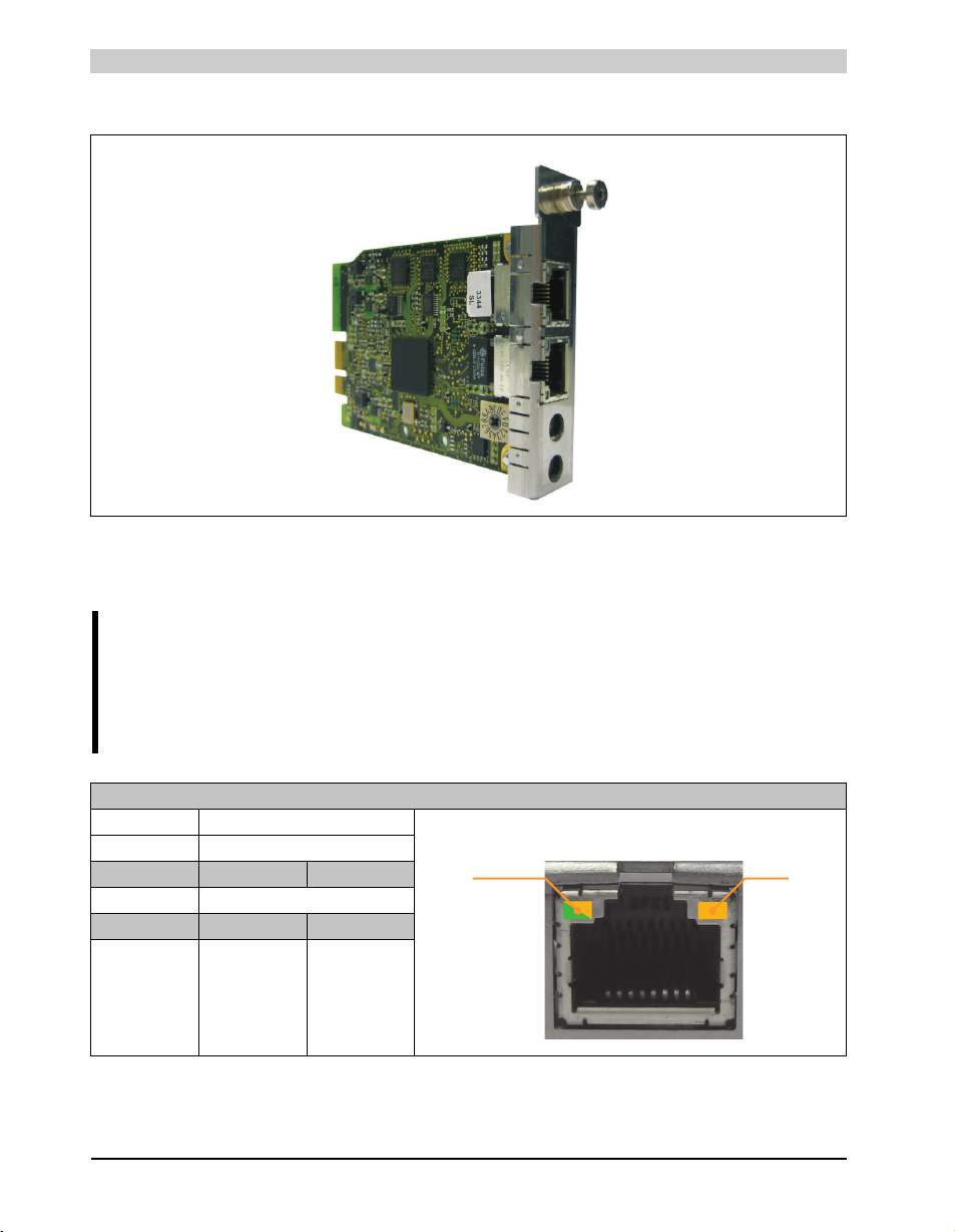
Technical data • Individual components
Speed LED
(green / orange)
Link LED
(orange)
3.8.2 POWERLINK card 2-port - 5ACPCC.MPL0-00
Figure 34: POWERLINK card 2-port - 5ACPCC.MPL0-00
Technical data
Information:
The following characteristics, features, and limit values only apply to this individual
component and can deviate from those specified for the entire device. For the entire
device in which this individual component is used, refer to the data given
specifically for the entire device.
POWERLINK card 2 connections
Cabling S/STP (Cat5e) The LEDs are identical for both connections.
Cable length max. 100 m (min. Cat5e)
Speed LED On Off
Green / red see Status / Error LED
Link LED On Blinking
Yellow Link
92
(POWERLINK
network
connection
available)
Activity (blinking)
(Data transfer in
progress)
Table 52: POWERLINK card 2-port connection
Panel PC 800 User's Manual V 1.00
Page 93
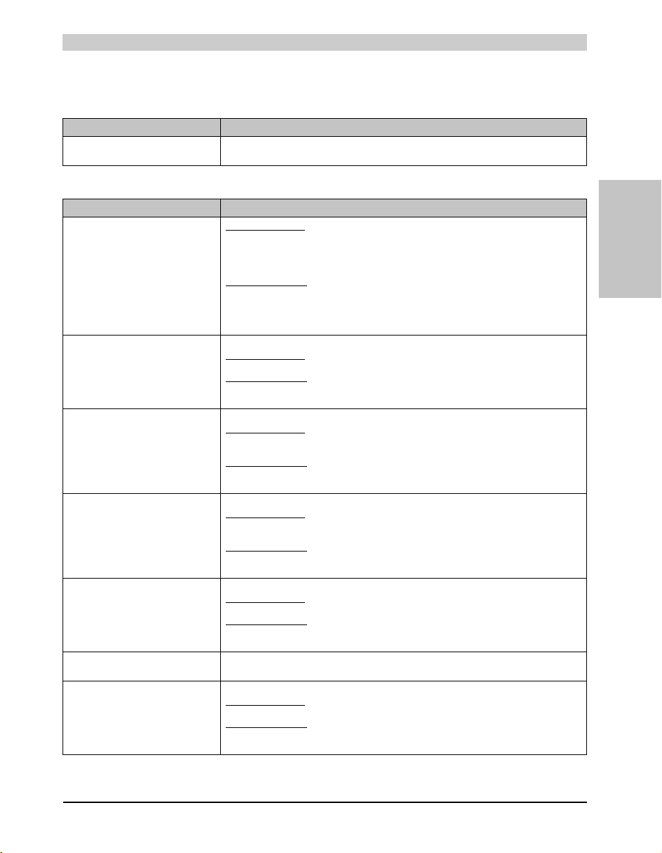
Technical data • Individual components
Status / Error LED
The status/error LED is a green/red LED.
Red - error Description
On The POWERLINK interface has encountered an error (failed Ethernet frames, increased number of
Table 53: Status / Error LED as error LED - POWERLINK card 2-port operating mode
Green - status Description
Off
NOT_ACTIVE
Green flickering (approx. 10 Hz)
BASIC_ETHERNET
Single flash (approx. 1 Hz)
PRE_OPERATIONAL_1
Double flash (approx. 1 Hz)
PRE_OPERATIONAL_2
Triple flash (approx. 1 Hz)
READY_TO_OPERATE
On
OPERATIONAL
Blinking (approx. 2.5 Hz)
STOPPED
Table 54: Status / Error LED as status LED - POWERLINK card 2-port operating mode
collisions on the network, etc.).
Managing Node (MN)
The bus is monitored for POWERLINK frames. If a frame is not received within the configured time
window (timeout), the interface goes directly into PRE_OPERATIONAL_1 status (single flash).
If, however, POWERLINK communication is detected before this time passes, the interface goes
directly into the BASIC_ETHERNET status (flickering).
Controlled Node (CN)
The bus is monitored for POWERLINK frames. If a frame is not received within the configured time
window (timeout), the interface goes directly into BASIC_ETHERNET status (flickering).
If, however, POWERLINK communication is detected during this time, the interface goes directly into
the PRE_OPERATIONAL_1 status (single flash).
The interface is in BASIC_ETHERNET status, and is operated purely as an Ethernet TCP/IP interface.
Managing Node (MN)
This status can only be changed by resetting the interface.
Controlled Node (CN)
If POWERLINK communication is detected while in this status, the interface goes into the
PRE_OPERATIONAL_1 state (single flash).
The interface status is PRE_OPERATIONAL_1.
Managing Node (MN)
The MN starts the operation of the "reduced cycle". Collisions are allowed on the bus. There is not yet
any cyclic communication.
Controlled Node (CN)
The CN waits until it receives an SoC frame and then switches to PRE_OPERATIONAL_2 status
(double flash).
The interface status is PRE_OPERATIONAL_2.
Managing Node (MN)
The MN begins with the cyclic communication (cyclic input data is not yet evaluated). The CNs are
configured in this status.
Controlled Node (CN)
In this status, the interface is normally configured by the manager. After this, a command changes the
status to PRE_OPERATIONAL_3 (triple flash).
The interface status is READY_TO_OPERATE.
Managing Node (MN)
Normal cyclic and asynchronous communication. Received PDO data is ignored.
Controlled Node (CN)
The configuration of the interface is complete. Normal cyclic and asynchronous communication.
The PDO data sent corresponds to the PDO mapping used. However, cyclic data is not yet evaluated.
The interface status is OPERATIONAL.
The interface status is STOPPED.
Managing Node (MN)
This status is not possible for the MN.
Controlled Node (CN)
No output data is produced and no input data is received. Only the appropriate command from the
manager can enter or leave this state.
Section 2
Technical data
93Panel PC 800 User's Manual V 1.00
Page 94
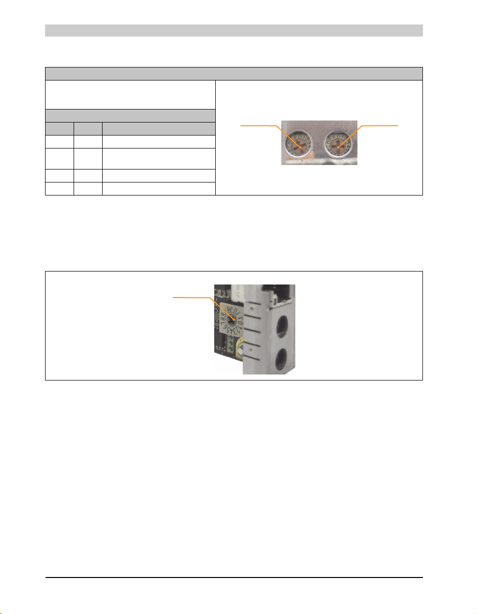
Technical data • Individual components
Station number
x1
Station number
x16
Card number
switch
POWERLINK station number
POWERLINK station number (x1, x16)
Both of these hex switches (x16, x1) are used to configure the
station number for the POWERLINK. Station numbers are
permitted between #00 and #FD.
Switch position
x1 x16 Description
0 0 Operation as managing node
1 ... D 0 ... F station number
E F Reserved
F F Reserved
Operation as controlled node
Table 55: POWERLINK card 2-port station number (x1, x16)
Card number switch
The one-digit card number ($1 – $F) is configured using the card number switch. This number is
used to identify the module.
Figure 35: POWERLINK card 2-port node number switch
94
Panel PC 800 User's Manual V 1.00
Page 95
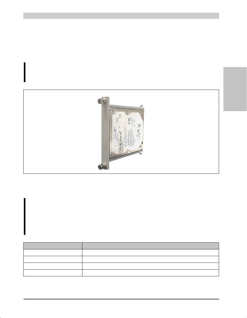
Technical data • Individual components
3.9 Drives
3.9.1 Slide-in compact HDD 40GB EE25 - 5AC801.HDDI-00
This hard disk is specified for 24-hour operation and also provides an extended temperature
specification.
Information:
The option 5AC803.BC02-00 is required for the use of slide-in compact drives.
Section 2
Technical data
Figure 36: Slide-in compact HDD 40GB EE25 - 5AC801.HDDI-00
Technical data
Information:
The following characteristics, features, and limit values only apply to this individual
component and can deviate from those specified for the entire device. For the entire
device in which this individual component is used, refer to the data given
specifically for the entire device.
Features 5AC801.HDDI-00
Manufacturer's product ID Seagate ST940817SM
Formatted capacity 40 GB
Number of heads 1
Number of sectors (user) 78,140,160
Table 56: Technical data - Add-on hard disk - 5AC801.HDDI-00
95Panel PC 800 User's Manual V 1.00
Page 96
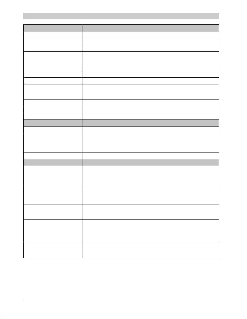
Technical data • Individual components
Features 5AC801.HDDI-00
Bytes per sector 512
Revolution speed 5400 rpm
Access time (average) 12.5 ms
Positioning time (seek, typical values)
Minimum (track to track)
Average (read access)
Maximum (read access)
Starting time (0 rpm to read access) 3 seconds (typically)
Interface SATA
Data transfer rate
Internal
To/from host
Cache 8 MB
S.M.A.R.T. Support Yes
MTBF 750,000 Power On Hours
Mechanical characteristics
Slide-in compact mounting Fixed
Outer dimensions
Height
Width
Depth
Weight 134 g
Environmental characteristics
Ambient temperature
Operation - Standard / 24-hour
Bearings
Transport
Relative humidity
Operation
Bearings
Transport
Vibration
Operation
Bearings
Shock (pulse with a sine half-wave)
Operation
Bearings
Altitude
Operation
Bearings
2)
3)
Max. 150 MB/s (Ultra-DMA Mode 5)
2 g at 5 - 500 Hz, no non-recovered errors
5 g at 5 - 500 Hz, no non-recovered errors
300 g and 2 ms duration, no non-recovered errors
150 g and 11 ms duration, no non-recovered errors
800 g and 2 ms duration, no non-recovered errors
400 g and 0.5 ms duration, no non-recovered errors
Table 56: Technical data - Add-on hard disk - 5AC801.HDDI-00 (cont.)
1 ms
12.5 ms
23 ms
Max. 450 MBit/s
98 mm
13 mm
105 mm
-30 to +85°C
-40 to +95°C
-40 to +95°C
5 to 90%, non-condensing
5 to 95%, non-condensing
5 to 95%, non-condensing
- 300 to 5000 m
- 300 to 12,192 m
1)
1) With 8760 POH (Power On Hours) per year and 70°C surface temperature.
2) Temperature values for 305 meter altitude. The temperature specification must be reduced linearly by 1°C every 305 meters. The
temperature increase and decrease can be a maximum of 20°C per hour.
3) Humidity gradient: Maximum 15% per hour.
96
Panel PC 800 User's Manual V 1.00
Page 97
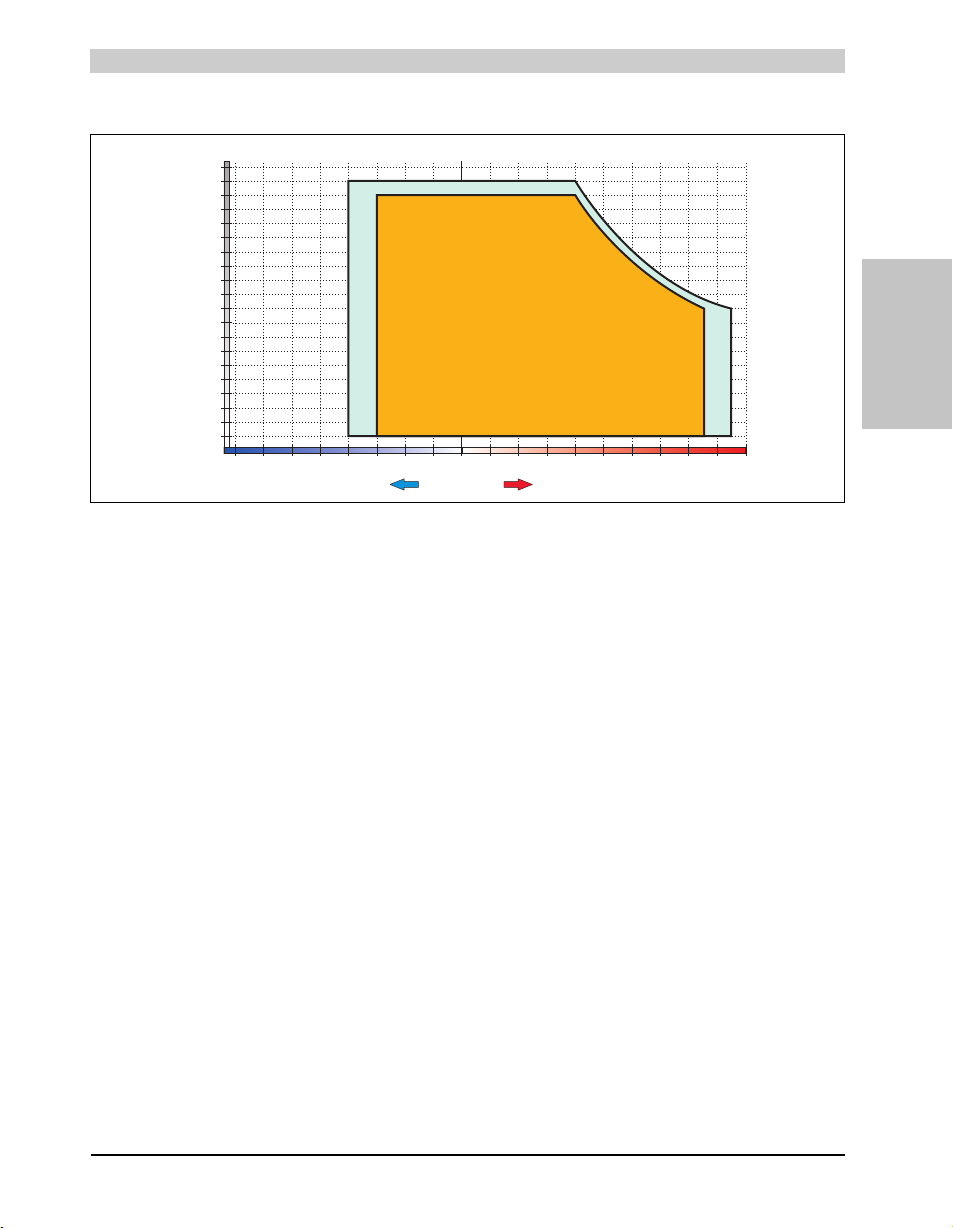
Technical data • Individual components
Temperature [°C]
+
-
Relative humidity [%RH] (non-condensing)
Operation
Storage / Transport
0102030405060708090-80 -70 -60 -50 -40 -30 -20 -10 100
0
5
10
100
95
90
85
80
75
70
65
60
55
50
45
40
35
30
25
20
15
Temperature humidity diagram - Operation and storage
Figure 37: Temperature humidity diagram - 5AC801.HDDI-00
Temperature values for 305 meter altitude. The temperature specification must be reduced
linearly by 1°C every 305 meters. The temperature increase and decrease can be a maximum
of 20°C per hour.
Section 2
Technical data
97Panel PC 800 User's Manual V 1.00
Page 98
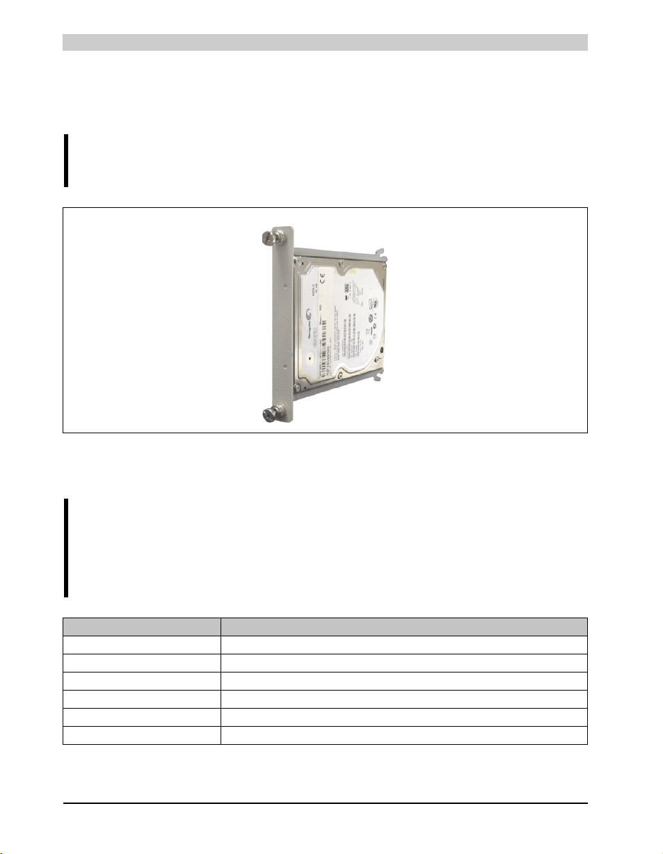
Technical data • Individual components
3.9.2 Slide-in compact HDD 160 GB 24x7 ET - 5AC801.HDDI-02
This hard disk is specified for 24-hour operation (24x7) and also provides an extended
temperature specification (ET).
Information:
The option 5AC803.BC02-00 is required for the use of slide-in compact drives.
Figure 38: Slide-in compact HDD 160 GB - 5AC801.HDDI-02
Technical data
Information:
The following characteristics, features, and limit values only apply to this individual
component and can deviate from those specified for the entire device. For the entire
device in which this individual component is used, refer to the data given
specifically for the entire device.
Features 5AC801.HDDI-02
Manufacturer's product ID Fujitsu MHY2160BH-ESW
Formatted capacity 160 GB
Number of heads 3
Number of sectors (user) 312,581,808
Bytes per sector 512
Revolution speed 5400 rpm
Table 57: Technical data - Slide-in compact HDD - 5AC801.HDDI-02
98
Panel PC 800 User's Manual V 1.00
Page 99
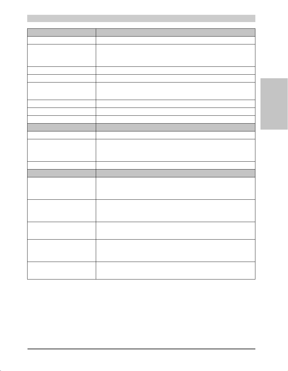
Technical data • Individual components
Features 5AC801.HDDI-02
Access time (average) 12 ms
Positioning time (seek, typical values)
Minimum (track to track)
Average (read access)
Maximum (read access)
Starting time (0 rpm to read access) 4 seconds (typically)
Interface SATA
Data transfer rate
Internal
To/from host
Cache 8 MB
S.M.A.R.T. Support Yes
MTBF 300,000 Power On Hours
Mechanical characteristics
Slide-in compact mounting Fixed
Outer dimensions
Height
Width
Depth
Weight 135 g
Environmental characteristics
Ambient temperature
Operation - Standard / 24-hour
Bearings
Transport
Relative humidity
Operation
Bearings
Transport
Vibration
Operation
Bearings
Shock (pulse with a sine half-wave)
Operation
Bearings
Altitude
Operation
Bearings
2)
3)
Max. 150 MB/s (Ultra-DMA Mode 5)
8 to 90% non-condensing (maximum humidity at +29°C)
5 to 95% non-condensing (maximum humidity at +40°C)
5 to 95% non-condensing (maximum humidity at +40°C)
5 - 500 Hz: 1 g, no unrecoverable errors
325 g, 2 ms, no unrecoverable errors
Table 57: Technical data - Slide-in compact HDD - 5AC801.HDDI-02 (cont.)
1.5 ms
12 ms
22 ms
Max. 84.6 MBit/s
98 mm
13 mm
105 mm
-15 to +80°C
-40 to +95°C
-40 to +95°C
5 - 500 Hz: 5 g, no damage
900 g, 1 ms, no damage
120 g, 11 ms, no damage
- 300 to 3000 m
- 300 to 12,192 m
Section 2
1)
Technical data
1) With 8760 POH (Power On Hours) per year and 70°C surface temperature.
2) Temperature values for 305 meter altitude. The temperature specification must be reduced linearly by 1°C every 305 meters. The
temperature increase and decrease can be a maximum of 20°C per hour.
3) Humidity gradient: Maximum 15% per hour.
99Panel PC 800 User's Manual V 1.00
Page 100
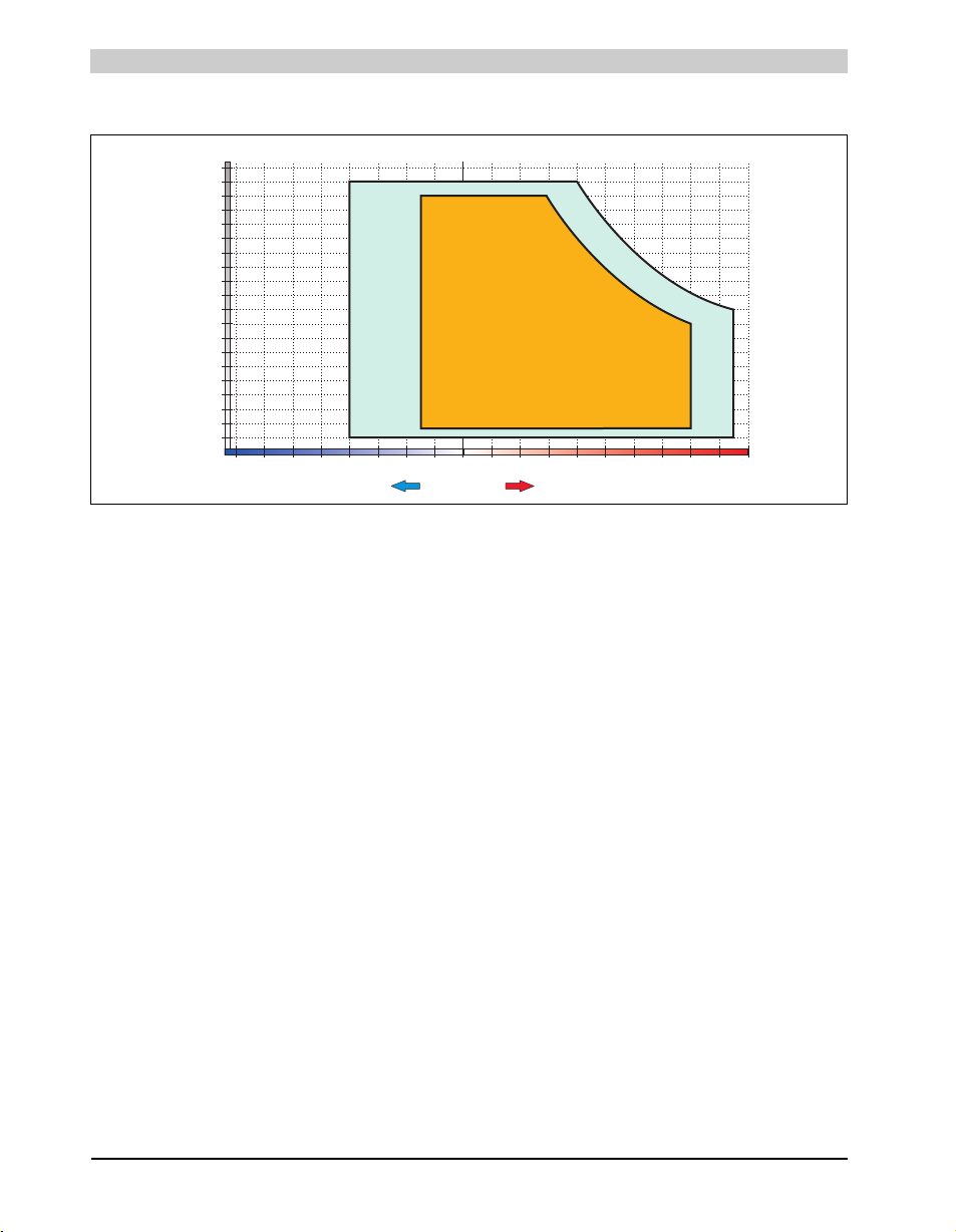
Technical data • Individual components
Temperature [°C]
+
-
Relative humidity [%RH] (non-condensing)
Operation
Storage
Transport
0102030405060708090-80 -70 -60 -50 -40 -30 -20 -10 100
0
5
10
100
95
90
85
80
75
70
65
60
55
50
45
40
35
30
25
20
15
Temperature humidity diagram - Operation and storage
Figure 39: Temperature humidity diagram - 5AC801.HDDI-02
Temperature values for 305 meter altitude. The temperature specification must be reduced
linearly by 1°C every 305 meters. The temperature increase and decrease can be a maximum
of 20°C per hour.
100
Panel PC 800 User's Manual V 1.00
 Loading...