

Page 1

Automation PC 910
User's manual
Version: 1.51 (June 2018)
Model no.: MAAPC900-ENG
Translation of the original manual
All values in this manual are current as of its publication. We reserve the right to change the contents of this manual
without notice. B&R Industrial Automation GmbH is not liable for technical/editorial errors or incomplete information
in this manual. In addition, B&R Industrial Automation GmbH shall not be liable for incidental or consequential
damages in connection with or arising from the furnishing, performance or use of this material. The software names,
hardware names and trademarks used in this document are registered by their respective companies.
Automation PC 910 user's manual V1.51 1
Page 2

Publishing information
Publishing information
B&R Industrial Automation GmbH
B&R Strasse 1
5142 Eggelsberg
Austria
Telephone: +43 7748 6586-0
Fax: +43 7748 6586-26
The place of jurisdiction, in accordance with article 17 of the European Convention on Courts of Jurisdiction and
Enforcement, is A-4910
Ried im Innkreis, Austria, commercial register court: Ried im Innkreis, Austria
Commercial register number: FN 111651 v.
The place of fulfillment in accordance with article 5 of the European Convention on Courts of Jurisdiction and
Enforcement is A-5142 Eggelsberg, Austria
Austrian DVR no.: 0721301
VATIN: ATU62367156
2 Automation PC 910 user's manual V1.51
Page 3

Chapter index
Chapter 1: General information
Chapter 2: Technical data
Chapter 3: Commissioning
Chapter 4: Software
Chapter index
Chapter 5: Standards and certifications
Chapter 6: Accessories
Chapter 7: Servicing and maintenance
Appendix A
Automation PC 910 user's manual V1.51 3
Page 4

Table of contents
Chapter 1 General information................................................................................. 13
1 Manual history..................................................................................................................................................13
2 Safety guidelines..............................................................................................................................................17
2.1 Intended use...............................................................................................................................................17
2.2 Protection against electrostatic discharge..................................................................................................17
2.2.1 Packaging..............................................................................................................................................17
2.2.2 Guidelines for proper ESD handling.....................................................................................................17
2.3 Policies and procedures.............................................................................................................................17
2.4 Transport and storage................................................................................................................................18
2.5 Installation...................................................................................................................................................18
2.6 Operation.................................................................................................................................................... 18
2.6.1 Protection against touching electrical parts.......................................................................................... 18
2.6.2 Environmental conditions - Dust, moisture, corrosive gases................................................................18
2.6.3 Viruses and dangerous programs........................................................................................................ 19
2.7 Environmentally friendly disposal............................................................................................................... 19
2.7.1 Separation of materials.........................................................................................................................19
2.8 Security concept......................................................................................................................................... 19
2.9 Third-party software updates......................................................................................................................19
2.10 Administrator accounts............................................................................................................................. 19
3 Organization of safety notices......................................................................................................................... 20
4 Guidelines.........................................................................................................................................................20
5 Overview...........................................................................................................................................................21
Chapter 2 Technical data.......................................................................................... 25
1 Introduction.......................................................................................................................................................25
1.1 Intel Core i-series processors for the most demanding tasks....................................................................25
1.2 Maximum performance...............................................................................................................................25
1.3 Availability and reliability for many productive years................................................................................. 25
1.4 Features......................................................................................................................................................26
1.5 System components / Configuration.......................................................................................................... 27
1.5.1 Configuration - Base system................................................................................................................ 27
1.5.2 Accessory and software configuration..................................................................................................30
2 Complete system............................................................................................................................................. 31
2.1 Environmental characteristics.....................................................................................................................31
2.1.1 Temperature specifications...................................................................................................................31
2.1.2 Humidity specifications..........................................................................................................................41
2.2 Electrical characteristics............................................................................................................................. 42
2.2.1 Power management.............................................................................................................................. 42
2.2.2 Block diagrams......................................................................................................................................52
2.3 Serial number sticker..................................................................................................................................62
2.4 Device interfaces and slots........................................................................................................................ 63
2.4.1 Device interfaces - Overview................................................................................................................ 63
2.4.2 Power supply +24 VDC........................................................................................................................ 65
2.4.3 COM1 serial interface........................................................................................................................... 66
2.4.4 Panel/Monitor interface......................................................................................................................... 67
2.4.5 DisplayPort interface............................................................................................................................. 69
2.4.6 Ethernet 1 interface (ETH1)..................................................................................................................70
2.4.7 Ethernet 2 interface (ETH2)..................................................................................................................70
2.4.8 USB interfaces...................................................................................................................................... 71
2.4.9 IF option 1 slot......................................................................................................................................72
2.4.10 IF option 2 slot....................................................................................................................................72
2.4.11 Monitor/Panel option........................................................................................................................... 73
2.4.12 Card slot (PCI/PCIe)........................................................................................................................... 74
2.4.13 LED status indicators..........................................................................................................................75
2.4.14 Power button....................................................................................................................................... 76
2.4.15 Reset button........................................................................................................................................76
2.4.16 Battery................................................................................................................................................. 77
4 Automation PC 910 user's manual V1.51
Page 5

Table of contents
2.4.17 CFast slot............................................................................................................................................ 77
2.4.18 Slide-in compact slot...........................................................................................................................78
2.4.19 Slide-in slot 1...................................................................................................................................... 78
2.4.20 Slide-in slot 2...................................................................................................................................... 79
2.4.21 Trusted Platform Module (TPM)......................................................................................................... 79
3 Individual components..................................................................................................................................... 80
3.1 System units............................................................................................................................................... 80
3.1.1 5PC910.SX01-00...................................................................................................................................80
3.1.2 5PC910.SX02-00...................................................................................................................................86
3.1.3 5PC910.SX05-00...................................................................................................................................92
3.2 QM77 CPU boards..................................................................................................................................... 98
3.2.1 5PC900.TS77-0x...................................................................................................................................98
3.3 HM76 CPU boards................................................................................................................................... 100
3.3.1 5PC900.TS77-0x.................................................................................................................................100
3.4 QM170 CPU boards.................................................................................................................................102
3.4.1 5PC900.TS17-00, 04.......................................................................................................................... 102
3.5 HM170 CPU boards................................................................................................................................. 104
3.5.1 5PC900.TS17-01, -02......................................................................................................................... 104
3.6 CM236 CPU boards................................................................................................................................. 106
3.6.1 5PC900.TS17-03.................................................................................................................................106
3.7 Main memory............................................................................................................................................108
3.7.1 5MMDDR.xxxx-03............................................................................................................................... 108
3.7.2 5MMDDR.xxxx-04............................................................................................................................... 109
3.8 Bus units...................................................................................................................................................110
3.8.1 5AC901.BX0x-0x.................................................................................................................................110
3.9 Heat sinks.................................................................................................................................................114
3.9.1 5AC901.HS0x-00.................................................................................................................................114
3.9.2 5AC901.HS0x-01.................................................................................................................................114
3.9.3 5AC901.HS00-02................................................................................................................................ 115
3.10 Fan kits................................................................................................................................................... 116
3.10.1 5AC901.FA01-00...............................................................................................................................116
3.10.2 5AC901.FA02-00...............................................................................................................................118
3.10.3 5AC901.FA05-00...............................................................................................................................119
3.11 Drives...................................................................................................................................................... 120
3.11.1 5AC901.CHDD-00............................................................................................................................. 120
3.11.2 5AC901.CHDD-01............................................................................................................................. 123
3.11.3 5MMHDD.0500-00.............................................................................................................................125
3.11.4 5AC901.CSSD-00..............................................................................................................................128
3.11.5 5AC901.CSSD-01..............................................................................................................................130
3.11.6 5AC901.CSSD-02..............................................................................................................................132
3.11.7 5AC901.CSSD-03..............................................................................................................................134
3.11.8 5AC901.CSSD-04..............................................................................................................................137
3.11.9 5AC901.CSSD-05..............................................................................................................................140
3.11.10 5AC901.CSSD-06............................................................................................................................143
3.11.11 5MMSSD.0060-00........................................................................................................................... 146
3.11.12 5MMSSD.0060-01........................................................................................................................... 148
3.11.13 5MMSSD.0128-01........................................................................................................................... 151
3.11.14 5MMSSD.0180-00........................................................................................................................... 154
3.11.15 5MMSSD.0256-00........................................................................................................................... 156
3.11.16 5MMSSD.0512-00........................................................................................................................... 159
3.11.17 5AC901.CCFA-00............................................................................................................................161
3.11.18 5AC901.CHDD-99........................................................................................................................... 162
3.11.19 5AC901.SDVW-00...........................................................................................................................163
3.11.20 5AC901.SSCA-00............................................................................................................................166
3.11.21 5ACPCI.RAIC-06............................................................................................................................. 168
3.12 Interface options..................................................................................................................................... 172
3.12.1 5AC901.I485-00................................................................................................................................ 172
Table of contents
Automation PC 910 user's manual V1.51 5
Page 6

Table of contents
3.12.2 5AC901.ICAN-00...............................................................................................................................176
3.12.3 5AC901.ICAN-01...............................................................................................................................179
3.12.4 5AC901.IHDA-00...............................................................................................................................182
3.12.5 5AC901.ISRM-00.............................................................................................................................. 184
3.12.6 5AC901.IPLK-00................................................................................................................................186
3.12.7 5AC901.IRDY-00...............................................................................................................................190
3.12.8 5AC901.ISIO-00................................................................................................................................ 192
3.12.9 5AC901.IETH-00............................................................................................................................... 195
3.13 Monitor/Panel options.............................................................................................................................197
3.13.1 5AC901.LDPO-00..............................................................................................................................197
3.13.2 5AC901.LSDL-00.............................................................................................................................. 199
3.13.3 5AC901.LSD3-00.............................................................................................................................. 202
3.13.4 5AC901.LSD4-00.............................................................................................................................. 205
3.14 Uninterruptible power supply (UPS).......................................................................................................208
3.14.1 Requirements.................................................................................................................................... 208
3.14.2 5AC901.IUPS-00...............................................................................................................................209
3.14.3 5AC901.IUPS-01...............................................................................................................................211
3.14.4 5AC901.BUPS-00..............................................................................................................................213
3.14.5 5AC901.BUPS-01..............................................................................................................................217
3.14.6 5CAUPS.xxxx-01...............................................................................................................................221
3.15 Front covers............................................................................................................................................223
3.15.1 5AC901.FF0x-00............................................................................................................................... 223
Chapter 3 Commissioning.......................................................................................225
1 Installation...................................................................................................................................................... 225
1.1 Important information concerning installation/commissioning.................................................................. 225
1.2 Procedure................................................................................................................................................. 226
1.3 Mounting orientations............................................................................................................................... 227
1.3.1 Vertical mounting orientation.............................................................................................................. 227
1.3.2 Horizontal mounting orientation.......................................................................................................... 227
1.3.3 Mounting orientation - Floor-mounted.................................................................................................228
1.4 Spacing for air circulation.........................................................................................................................229
2 Cable connections..........................................................................................................................................230
3 Grounding concept.........................................................................................................................................231
4 General instructions for performing temperature testing............................................................................... 232
4.1 Procedure................................................................................................................................................. 232
4.2 Evaluating temperatures in Windows operating systems........................................................................ 232
4.2.1 Evaluating with the B&R Control Center............................................................................................ 232
4.2.2 Evaluating with the BurnInTest tool from Passmark...........................................................................233
4.3 Evaluating temperatures in non-Windows operating systems................................................................. 234
4.4 Evaluating the measurement results........................................................................................................234
5 Configuring a SATA RAID set.......................................................................................................................235
5.1 Create RAID set....................................................................................................................................... 236
5.2 Create RAID set - Striped........................................................................................................................236
5.3 Create RAID set - Mirrored......................................................................................................................237
5.4 Delete RAID set........................................................................................................................................237
5.5 Rebuild mirrored set.................................................................................................................................238
5.6 Resolve conflicts.......................................................................................................................................238
5.7 Low level format....................................................................................................................................... 239
6 Configuring a SATA RAID set using the internal RAID controller................................................................. 240
6.1 Create RAID volume................................................................................................................................ 241
6.2 Delete RAID volume.................................................................................................................................242
6.3 Reset disks to non-RAID..........................................................................................................................243
6.4 Recovery volume options.........................................................................................................................244
7 Known problems / Issues.............................................................................................................................. 245
6 Automation PC 910 user's manual V1.51
Page 7

Table of contents
Chapter 4 Software.................................................................................................. 246
1 BIOS options.................................................................................................................................................. 246
1.1 General information.................................................................................................................................. 246
1.2 BIOS Setup and boot procedure..............................................................................................................246
1.2.1 BIOS Setup keys................................................................................................................................ 247
1.3 BIOS TS77............................................................................................................................................... 248
1.3.1 Main.....................................................................................................................................................248
1.3.2 Advanced.............................................................................................................................................250
1.3.3 Boot..................................................................................................................................................... 302
1.3.4 Security................................................................................................................................................305
1.3.5 Save & Exit......................................................................................................................................... 306
1.3.6 BIOS default settings.......................................................................................................................... 308
1.3.7 Allocation of resources....................................................................................................................... 314
1.4 BIOS TS17............................................................................................................................................... 317
1.4.1 Main.....................................................................................................................................................317
1.4.2 Advanced.............................................................................................................................................320
1.4.3 Chipset................................................................................................................................................ 374
1.4.4 Security................................................................................................................................................378
1.4.5 Boot..................................................................................................................................................... 380
1.4.6 Save & Exit......................................................................................................................................... 382
1.4.7 Allocation of resources....................................................................................................................... 384
2 Upgrade information.......................................................................................................................................387
2.1 BIOS upgrade...........................................................................................................................................387
2.1.1 Important information.......................................................................................................................... 387
2.1.2 Procedure with MS-DOS.................................................................................................................... 388
2.1.3 Procedure in EFI shell........................................................................................................................ 388
2.2 Firmware upgrade.................................................................................................................................... 389
2.2.1 Procedure in Windows (B&R Control Center).................................................................................... 389
2.3 Creating an MS-DOS boot diskette in Windows XP................................................................................390
2.4 Creating a bootable USB flash drive for B&R upgrade files.................................................................... 392
2.4.1 Requirements...................................................................................................................................... 392
2.4.2 Procedure............................................................................................................................................392
2.4.3 How to access MS-DOS.....................................................................................................................392
2.5 Creating a bootable mass storage device for B&R upgrade files............................................................393
2.5.1 Requirements...................................................................................................................................... 393
2.5.2 Procedure............................................................................................................................................393
2.5.3 How to access MS-DOS.....................................................................................................................393
3 Windows 10 IoT Enterprise 2016 LTSB........................................................................................................ 394
3.1 General information.................................................................................................................................. 394
3.2 Order data................................................................................................................................................ 394
3.3 Overview................................................................................................................................................... 394
3.4 Features....................................................................................................................................................394
3.5 Installation.................................................................................................................................................395
3.6 Drivers.......................................................................................................................................................395
3.7 Activation.................................................................................................................................................. 395
3.8 Issues and limitations...............................................................................................................................396
3.9 Supported display resolutions.................................................................................................................. 396
4 Windows 10 IoT Enterprise 2015 LTSB........................................................................................................ 397
4.1 General information.................................................................................................................................. 397
4.2 APC910 - Order data............................................................................................................................... 397
4.3 Overview................................................................................................................................................... 397
4.4 Features....................................................................................................................................................397
4.5 Installation.................................................................................................................................................397
4.6 Drivers.......................................................................................................................................................398
4.7 Activation.................................................................................................................................................. 398
4.8 Recovery DVD - Content of delivery........................................................................................................398
4.9 Issues and limitations...............................................................................................................................399
Table of contents
Automation PC 910 user's manual V1.51 7
Page 8

Table of contents
4.10 Supported display resolutions................................................................................................................ 399
5 Windows Embedded 8.1 Industry Pro........................................................................................................... 400
5.1 General information.................................................................................................................................. 400
5.2 Order data................................................................................................................................................ 400
5.3 Overview................................................................................................................................................... 400
5.4 Features....................................................................................................................................................400
5.5 Installation.................................................................................................................................................401
5.6 Drivers.......................................................................................................................................................401
5.7 Activation.................................................................................................................................................. 401
5.8 Contents of the Recovery DVD................................................................................................................402
5.9 Lockdown features................................................................................................................................... 402
5.10 Supported display resolutions................................................................................................................ 402
6 Windows 7......................................................................................................................................................403
6.1 General information.................................................................................................................................. 403
6.2 Order data................................................................................................................................................ 403
6.3 Overview................................................................................................................................................... 404
6.4 Installation.................................................................................................................................................404
6.4.1 Installing on the PCI SATA RAID controller - 5ACPCI.RAIC-06........................................................ 404
6.4.2 Installing on the internal RAID controller (QM77)...............................................................................405
6.5 Drivers.......................................................................................................................................................405
6.6 Issues and limitations...............................................................................................................................405
7 Windows Embedded Standard 7................................................................................................................... 406
7.1 General information.................................................................................................................................. 406
7.2 Order data................................................................................................................................................ 406
7.3 Overview................................................................................................................................................... 406
7.4 Features....................................................................................................................................................407
7.5 Installation.................................................................................................................................................407
7.6 Drivers.......................................................................................................................................................407
7.6.1 Touch screen driver............................................................................................................................ 408
7.7 Supported display resolutions.................................................................................................................. 408
8 Windows XP Professional..............................................................................................................................409
8.1 General information.................................................................................................................................. 409
8.2 Order data................................................................................................................................................ 409
8.3 Overview................................................................................................................................................... 409
8.4 Installation.................................................................................................................................................409
8.4.1 Installing on the PCI SATA RAID controller - 5ACPCI.RAIC-06........................................................ 410
8.4.2 Installing on the internal RAID controller (QM77) or in AHCI mode................................................... 410
8.5 Drivers.......................................................................................................................................................410
9 Windows Embedded Standard 2009............................................................................................................. 411
9.1 General information.................................................................................................................................. 411
9.2 Order data................................................................................................................................................ 411
9.3 Overview................................................................................................................................................... 411
9.4 Features....................................................................................................................................................411
9.5 Installation.................................................................................................................................................412
9.6 Drivers.......................................................................................................................................................412
9.7 Supported display resolutions.................................................................................................................. 412
10 Automation Runtime.....................................................................................................................................413
10.1 General information................................................................................................................................ 413
10.2 Order data.............................................................................................................................................. 413
10.3 Automation Runtime Windows (ARwin) with QM77/HM76 CPU boards................................................413
10.4 Automation Runtime Embedded (ARemb) with QM77/HM76 CPU boards........................................... 414
10.5 Automation Runtime Windows (ARwin) with QM170/HM170 CPU boards............................................ 414
10.6 Automation Runtime Embedded (ARemb) with QM170/HM170 CPU boards........................................414
10.7 Information regarding Automation Runtime operation........................................................................... 415
10.8 Technology Guarding............................................................................................................................. 416
11 B&R Hypervisor............................................................................................................................................ 417
12 mapp Technology.........................................................................................................................................418
8 Automation PC 910 user's manual V1.51
Page 9

Table of contents
13 B&R Linux 9 (GNU/Linux)............................................................................................................................419
13.1 General information................................................................................................................................ 419
13.2 Order data.............................................................................................................................................. 419
13.3 Overview................................................................................................................................................. 419
13.4 Features..................................................................................................................................................419
13.5 Installation...............................................................................................................................................419
13.6 Drivers.....................................................................................................................................................420
14 B&R Linux 8 (GNU/Linux)............................................................................................................................421
14.1 General information................................................................................................................................ 421
14.2 Order data.............................................................................................................................................. 421
14.3 Overview................................................................................................................................................. 421
14.4 Features..................................................................................................................................................421
14.5 Installation...............................................................................................................................................422
14.6 Drivers.....................................................................................................................................................422
15 B&R Automation Device Interface (ADI) Control Center............................................................................. 423
15.1 Functions................................................................................................................................................ 423
15.2 Installation...............................................................................................................................................424
16 B&R Automation Device Interface (ADI) Development Kit.......................................................................... 425
17 B&R Automation Device Interface (ADI) .NET SDK....................................................................................426
18 B&R Key Editor............................................................................................................................................427
19 B&R KCF Editor...........................................................................................................................................428
20 HMI Service Center..................................................................................................................................... 429
20.1 5SWUTI.0001-000.................................................................................................................................. 429
20.1.1 General information...........................................................................................................................429
20.1.2 Order data......................................................................................................................................... 429
Table of contents
Chapter 5 Standards and certifications................................................................. 430
1 Standards and guidelines.............................................................................................................................. 430
1.1 CE marking...............................................................................................................................................430
1.2 EMC directive........................................................................................................................................... 430
2 Certifications...................................................................................................................................................431
2.1 UL certification..........................................................................................................................................431
2.2 GOST-R.................................................................................................................................................... 431
2.3 EAC...........................................................................................................................................................431
2.4 KC............................................................................................................................................................. 432
2.5 RCM..........................................................................................................................................................432
2.6 DNV GL certification.................................................................................................................................432
Chapter 6 Accessories............................................................................................ 434
1 Power connectors.......................................................................................................................................... 434
1.1 0TB103.9x.................................................................................................................................................434
1.1.1 General information.............................................................................................................................434
1.1.2 Order data........................................................................................................................................... 434
1.1.3 Technical data.....................................................................................................................................434
2 Terminal block ready relay............................................................................................................................ 436
2.1 0TB2104.8000.......................................................................................................................................... 436
2.1.1 General information.............................................................................................................................436
2.1.2 Order data........................................................................................................................................... 436
2.1.3 Technical data.....................................................................................................................................436
3 Replacement CMOS batteries....................................................................................................................... 437
3.1 0AC201.91 / 4A0006.00-000....................................................................................................................437
3.1.1 General information.............................................................................................................................437
3.1.2 Order data........................................................................................................................................... 437
3.1.3 Technical data.....................................................................................................................................437
4 CFast cards....................................................................................................................................................438
4.1 General information.................................................................................................................................. 438
4.2 Basic information...................................................................................................................................... 438
Automation PC 910 user's manual V1.51 9
Page 10

Table of contents
4.2.1 Flash technology................................................................................................................................. 438
4.2.2 Wear leveling...................................................................................................................................... 438
4.2.3 ECC error correction...........................................................................................................................438
4.2.4 S.M.A.R.T. support.............................................................................................................................. 438
4.2.5 Calculating the expected service life for an existing application........................................................ 439
4.2.6 Dimensions..........................................................................................................................................439
4.3 5CFAST.xxxx-00....................................................................................................................................... 440
4.3.1 General information.............................................................................................................................440
4.3.2 Order data........................................................................................................................................... 440
4.3.3 Technical data.....................................................................................................................................440
4.3.4 Temperature/Humidity diagram...........................................................................................................443
4.4 5CFAST.xxxx-10....................................................................................................................................... 445
4.4.1 General information.............................................................................................................................445
4.4.2 Order data........................................................................................................................................... 445
4.4.3 Technical data.....................................................................................................................................445
4.4.4 Temperature/Humidity diagrams.........................................................................................................449
4.4.5 Write protection................................................................................................................................... 450
5 PCIe plug-in cards......................................................................................................................................... 451
5.1 5ACPCE.ETH1-00.................................................................................................................................... 451
5.1.1 General information.............................................................................................................................451
5.1.2 Order data........................................................................................................................................... 451
5.1.3 Technical data.....................................................................................................................................451
5.1.4 Driver support......................................................................................................................................452
5.1.5 Dimensions..........................................................................................................................................453
5.2 5ACPCE.ETH4-00.................................................................................................................................... 454
5.2.1 General information.............................................................................................................................454
5.2.2 Order data........................................................................................................................................... 454
5.2.3 Technical data.....................................................................................................................................454
5.2.4 Driver support......................................................................................................................................455
5.2.5 Dimensions..........................................................................................................................................456
6 USB flash drives............................................................................................................................................ 457
6.1 5MMUSB.xxxx-01..................................................................................................................................... 457
6.1.1 General information.............................................................................................................................457
6.1.2 Order data........................................................................................................................................... 457
6.1.3 Technical data.....................................................................................................................................457
6.1.4 Temperature/Humidity diagram...........................................................................................................459
6.2 5MMUSB.032G-02....................................................................................................................................459
6.2.1 General information.............................................................................................................................459
6.2.2 Order data........................................................................................................................................... 459
6.2.3 Technical data.....................................................................................................................................459
6.2.4 Temperature/Humidity diagram...........................................................................................................461
7 USB media drive............................................................................................................................................462
7.1 5MD900.USB2-02.....................................................................................................................................462
7.1.1 General information.............................................................................................................................462
7.1.2 Order data........................................................................................................................................... 462
7.1.3 Interfaces.............................................................................................................................................462
7.1.4 Technical data.....................................................................................................................................462
7.1.5 Dimensions..........................................................................................................................................464
7.1.6 Dimensions with front cover............................................................................................................... 465
7.1.7 Cutout installation................................................................................................................................465
7.1.8 Content of delivery..............................................................................................................................465
7.1.9 Installation........................................................................................................................................... 465
7.2 5A5003.03.................................................................................................................................................467
7.2.1 General information.............................................................................................................................467
7.2.2 Order data........................................................................................................................................... 467
7.2.3 Technical data.....................................................................................................................................467
7.2.4 Dimensions..........................................................................................................................................467
10 Automation PC 910 user's manual V1.51
Page 11

Table of contents
7.2.5 Content of delivery..............................................................................................................................468
7.2.6 Installation........................................................................................................................................... 468
8 Replacement disk tray................................................................................................................................... 469
8.1 5AC901.FRAM-00.....................................................................................................................................469
8.1.1 General information.............................................................................................................................469
8.1.2 Order data........................................................................................................................................... 469
8.1.3 Technical data.....................................................................................................................................469
8.1.4 Dimensions..........................................................................................................................................469
9 Cables............................................................................................................................................................ 470
9.1 DVI cables................................................................................................................................................ 470
9.1.1 5CADVI.0xxx-00..................................................................................................................................470
9.2 SDL cables............................................................................................................................................... 473
9.2.1 5CASDL.0xxx-00.................................................................................................................................473
9.3 SDL cables with 45° male connector.......................................................................................................476
9.3.1 5CASDL.0xxx-01.................................................................................................................................476
9.4 SDL flex cables........................................................................................................................................ 479
9.4.1 5CASDL.0xxx-03.................................................................................................................................479
9.5 SDL flex cables with extender................................................................................................................. 483
9.5.1 5CASDL.0xx0-13.................................................................................................................................483
9.6 SDL3/SDL4 cables................................................................................................................................... 487
9.6.1 5CASD3.xxxx-00................................................................................................................................. 487
9.7 USB cables...............................................................................................................................................490
9.7.1 5CAUSB.00xx-00................................................................................................................................ 490
9.8 RS232 cables........................................................................................................................................... 492
9.8.1 9A0014.xx.......................................................................................................................................... 492
9.9 Internal supply cable................................................................................................................................ 494
9.9.1 5CAMSC.0001-00............................................................................................................................... 494
10 Replacement fan.......................................................................................................................................... 495
10.1 5AC901.FI0x-00......................................................................................................................................495
10.1.1 General information...........................................................................................................................495
10.1.2 Order data......................................................................................................................................... 495
11 Line filter.......................................................................................................................................................496
11.1 5AC804.MFLT-00....................................................................................................................................496
11.1.1 General information...........................................................................................................................496
11.1.2 Order data......................................................................................................................................... 496
11.1.3 Technical data................................................................................................................................... 496
11.1.4 Dimensions........................................................................................................................................ 497
11.1.5 Drilling template.................................................................................................................................497
11.1.6 Connecting to the end device...........................................................................................................497
Table of contents
Chapter 7 Servicing and maintenance...................................................................498
1 Replacing the battery.....................................................................................................................................498
1.1 Evaluating the battery status....................................................................................................................498
1.2 Procedure................................................................................................................................................. 499
2 Exchanging a CFast card.............................................................................................................................. 500
3 Installing interface options............................................................................................................................. 501
4 Installing monitor/panel options..................................................................................................................... 504
5 Installing and exchanging slide-in compact drives........................................................................................ 507
6 Installing and exchanging slide-in drives.......................................................................................................510
7 Installing PCI/PCIe cards...............................................................................................................................513
8 Installing and connecting the UPS battery unit............................................................................................. 516
8.1 Permissible mounting orientations........................................................................................................... 516
9 Replacing fan filters....................................................................................................................................... 518
10 Replacing fan kits........................................................................................................................................ 519
11 Connecting an external device to the mainboard........................................................................................ 522
12 Replacing a PCI SATA RAID hard disk in a RAID 1 set.............................................................................525
12.1 Procedure............................................................................................................................................... 525
Automation PC 910 user's manual V1.51 11
Page 12

Table of contents
13 Repairs, complaints and replacement parts................................................................................................ 526
Appendix A .............................................................................................................. 527
1 Maintenance Controller Extended (MTCX)....................................................................................................527
2 Abbreviations..................................................................................................................................................528
3 Glossary......................................................................................................................................................... 528
12 Automation PC 910 user's manual V1.51
Page 13

General information • Manual history
Chapter 1 • General information
Information:
This user's manual is not intended for end customers! It is the responsibility of the machine manufacturer or system provider to provide the safety guidelines relevant to end customers in the operating
instructions for the end customer in the respective local language.
1 Manual history
Version Date Change
0.10 Preliminary 2012-06-12
1.00 2012-11-26
1.05 2013-03-19
1.10 2013-06-12
•
First version
•
Updated chapter 4 "Software" on page 246.
•
Updated chapter 7 "Servicing and maintenance" on page 498.
•
Updated "Appendix A" on page 527.
•
Modified "Organization of safety notices" on page 20. Updated descriptions for cautions and warnings.
•
Revised terminology in German edition.
•
Updated the following sections in chapter "Technical data": "Temperature specifications" on page 31,
"Block diagrams" on page 52, "Humidity specifications" on page 41.
•
Updated the following sections in chapter "Commissioning": "Mounting orientations" on page 227,
"Spacing for air circulation" on page 229, "Grounding concept" on page 231.
•
Updated CPU boards 5PC900.TS77-00, 5PC900.TS77-01, 5PC900.TS77-05, 5PC900.TS77-06,
5PC900.TS77-07 and 5PC900.TS77-08 in sections "QM77 CPU boards " on page 98 and "HM76 CPU
boards " on page 100.
•
Updated the following drives: "5AC901.CSSD-00" on page 128, "5AC901.CSSD-01" on page 130,
"5AC901.CSSD-02" on page 132, "5AC901.CCFA-00" on page 161.
•
Updated the following interface options: "5AC901.ICAN-00" on page 176, "5AC901.IHDA-00" on page
182, "5AC901.ISRM-00" on page 184.
•
Updated section "Monitor/Panel options" on page 197.
•
Updated heat sink 5AC901.HS01-00, see "5AC901.HS0x-00" on page 114.
•
Modified section "System components / Configuration" on page 27.
•
Updated bus units 5AC901.BX01-01 and 5AC901.BX02-01, see "Bus units" on page 110.
•
Updated "CFast cards" on page 438.
•
Updated USB media drive, see "5MD900.USB2-02" on page 462.
•
Updated the following sections in chapter 2 "Technical data": "Monitor/Panel option" on page 73,
"Slide-in slot 1" on page 78, "Uninterruptible power supply (UPS)" on page 208.
•
Updated the following drives: "5AC901.CHDD-01" on page 123, "5MMHDD.0500-00" on page 125,
"5AC901.CHDD-99" on page 162.
•
Updated the service life of the battery, see "Battery" on page 77.
•
Updated sections "BIOS options" on page 246 and "Upgrade information" on page 387 in chapter
4 "Software".
•
Updated sections "Replacing the battery" on page 498, "Installing PCI/PCIe cards" on page 513 and
"Connecting an external device to the mainboard" on page 522 in 7 "Servicing and maintenance".
•
Modified tables "Umgebungstemperatur mit Lüfter" on page and "Umgebungstemperatur ohne Lüfter"
on page .
•
Updated "Internal supply cable" on page 494.
•
Updated system unit "5PC910.SX05-00" on page 92.
•
Updated fan kit "5AC901.FA05-00" on page 119.
•
Updated front covers 5AC901.FF01-01, 5AC901.FF02-01, 5AC901.FF05-00 and 5AC901.FF05-01 on
page 223.
•
Updated slide-in compact drive "5AC901.CSSD-03" on page 134.
•
Updated replacement SSDs "5MMSSD.0060-00" on page 146, "5MMSSD.0060-01" on page 148 and
"5MMSSD.0180-00" on page 154.
•
Updated slide-in drives "5AC901.SDVW-00" on page 163 and "5AC901.SSCA-00" on page 166.
•
Updated bus units 5AC901.BX05-00, 5AC901.BX05-01 and 5AC901.BX05-02 on page 110.
•
Updated PCI RAID system "5ACPCI.RAIC-06" on page 168.
•
Updated the replacement fan kits on page 495.
•
Updated section "Slide-in slot 2" on page 79.
•
Updated chapter 5 "Standards and certifications" on page 430.
•
Updated section "Configuring a SATA RAID set using the internal RAID controller" on page 240.
•
Updated sections "Slide-in 1 features" on page 270 and "Slide-in 2 features" on page 272 in BIOS.
•
Revised section "Installing and connecting the UPS battery unit" on page 516.
•
Revised section "Power management" on page 42.
•
Modified Fig. 158 "PCI and PCIe routing with enabled APIC for QM77/HM76 CPU boards" on page 316.
•
Updated the BIOS version to V1.13, see "BIOS options" on page 246.
Chapter 1
General information
Table 1: Manual history
Automation PC 910 user's manual V1.51 13
Page 14

General information • Manual history
Version Date Change
1.05 2013-07-30
1.20 2014-04-14
1.21 2014-05-27
1.22 2014-08-25
1.25 2015-02-11
1.30 2015-09-30
•
•
•
•
•
•
•
•
•
•
•
•
•
•
•
•
•
•
•
•
•
•
•
•
•
•
•
•
•
•
•
•
•
•
•
•
•
•
•
•
•
•
•
•
•
•
•
•
•
•
•
•
•
•
•
•
Updated section "Fan control" on page 40.
Updated UPS cable 5CAUPS.0010-01, see "5CAUPS.xxxx-01" on page 221.
Updated B&R USB flash drive 5MMUSB.4096-01, see "USB flash drives" on page 457.
Updated slide-in compact drive "5AC901.CSSD-04" on page 137.
Updated replacement SSD "5MMSSD.0128-01" on page 151.
Updated UPS IF option "5AC901.IUPS-01" on page 211 and UPS battery unit "5AC901.BUPS-01" on
page 217.
Updated replacement disk tray "5AC901.FRAM-00" on page 469.
Updated tightening torque of locating screws in section "Cables" on page 470.
Updated 5AC901.BX02-02 and 5AC901.BX05-03 in section "Bus units" on page 110.
Updated sections "B&R Automation Device Interface (ADI) Development Kit" on page 425 and "B&R
Automation Device Interface (ADI) .NET SDK" on page 426.
Updated HM76 CPU boards 5PC900.TS77-09 and 5PC900.TS77-10 in section "5PC900.TS77-0x" on
page 100.
Revised sections "IF option 1 slot" on page 72 and "IF option 2 slot" on page 72.
Updated following section in "Windows 7": "Installing on the internal RAID controller (QM77)" on page
405.
Updated following section in "Windows XP Professional": "Installing on the internal RAID controller
(QM77) or in AHCI mode" on page 410.
Updated information about the discontinuation of support for the operating system "Windows XP Profes-
sional" on page 409.
Revised section "Automation Runtime" on page 413.
Updated "GL", "cULus HazLoc Class 1 Division 2" and "GOST-R" certification to the technical data for
several individual components.
Updated sections "GOST-R" on page 431 and "DNV GL certification " on page 432 in chapter 5
"Standards and certifications".
Updated the BIOS version to V1.15, see "BIOS options" on page 246.
Updated front covers 5AC901.FF01-02, 5AC901.FF02-02 and 5AC901.FF05-02 on page 223.
Updated monitor/panel option "5AC901.LSD3-00" on page 202.
Updated ready relay IF option "5AC901.IRDY-00" on page 190.
Updated slide-in compact drive "5AC901.CSSD-05" on page 140.
Updated replacement SSD "5MMSSD.0256-00" on page 156.
Corrected technical data for ambient temperature and humidity for the following drives:
"5AC901.CSSD-03" on page 134, "5AC901.CSSD-04" on page 137, "5MMSSD.0060-01" on page
148, "5MMSSD.0128-01", "5MMSSD.0256-00" on page 156.
Updated "Line filter" on page 496.
Updated SDL3 cables "5CASD3.xxxx-00" on page 487.
Updated service life diagram for the "5AC901.BUPS-00" and "5AC901.BUPS-01" battery units.
Corrected technical data for bus units with PCI Express slots – PCIe standard and bus speed, see "Tech-
nical data" on page 112.
Corrected Fig. 158 "PCI and PCIe routing with enabled APIC for QM77/HM76 CPU boards" on page
316.
Documented new revision of CFast cards, see "CFast cards" on page 438.
Corrected Fig. X "1-slot APC variant - Power calculation table" on page , Fig. X "2-slot APC variant - Power
calculation table" on page and Tab. 19 "5-slot APC variant - Power calculation table" on page 49.
Corrected Fig. 5 "Voltage supply for system units" on page 42.
Updated 5AC901.ISIO-00 interface option, see "Interface options" on page 172.
Updated "Windows Embedded 8.1 Industry Pro" on page 400.
Updated Fig. X "Revision der Einzelkomponenten mit GL-Zulassung" on page and Fig. X "GL-Zertifikat
Nr. 61 601 - 13 HH" on page .
Updated section "Mounting orientation - Floor-mounted" on page 228.
Updated section "Known problems / Issues" on page 245.
Updated the BIOS version to V1.19, see "BIOS options" on page 246.
Updated section "Automation Runtime" on page 413.
Updated 5CFAST.032G-10, 5CFAST.064G-10 and 5CFAST.128G-10 CFast cards, see "CFast cards" on
page 438.
Updated section "Fan control" on page 40.
Updated terminal block 0TB2104.8000 for ready relay, see "0TB2104.8000" on page 436.
Updated SDL cable 5CASDL.0008-00, see "SDL cables" on page 473.
Updated "B&R KCF Editor".
Updated "HMI Service Center" on page 429 (5SWUTI.0001-000).
Documented new revision of bus unit 5AC901.BX02-02, see "Bus units" on page 110.
Updated figure "Grounding concept" on page 231.
Revised section "SDL3 - LED status indicators" on page 204.
Updated section "B&R Automation Device Interface (ADI) Control Center" on page 423.
Updated "Humidity specifications" on page 41.
Updated MTCX controller, see "Maintenance Controller Extended (MTCX)" on page 527.
Updated section "DNV GL certification " on page 432.
Updated Debian 8 section, see "Debian (GNU/Linux)" on page .
Updated POWERLINK IF option "5AC901.IPLK-00" on page 186.
Revised overview of "Windows Embedded 8.1 Industry Pro", "Windows 7" and "Windows Embedded
Standard 7".
Table 1: Manual history
14 Automation PC 910 user's manual V1.51
Page 15

Version Date Change
1.31 2015-11-12
1.32 2016-01-28
1.35 2016-04-14
1.36 2016-08-02
•
•
•
•
•
•
•
•
•
•
•
•
•
•
•
•
•
•
•
•
•
•
General information • Manual history
Updated slide-in compact drive "5AC901.CSSD-06" on page 143.
Updated replacement SSD "5MMSSD.0512-00" on page 159.
Updated 0TG1000.02 Technology Guard (HID), see "Automation Runtime" on page 413.
Updated slide-in compact drive "5AC901.CHDD-99" on page 162.
Updated the BIOS version to V1.23, see "BIOS options" on page 246.
Correct PCI slot assignment n "PCI and PCIe routing with enabled APIC for QM77/HM76 CPU boards"
on page 316.
Renamed SO-DIMM 1 and SO-DIMM 2 to CPU board sensor 3 and CPU board sensor 4, see "Temper-
ature sensor locations" on page 39.
Updated "Humidity specifications" on page 41.
Updated drives "5AC901.CHDD-01" on page 123 and "5MMHDD.0500-00" on page 125.
Documented new revisions of drives "5AC901.CSSD-03", "5AC901.CSSD-04", "5AC901.CSSD-05",
"5MMSSD.0060-01", "5MMSSD.0128-01" and "5MMSSD.0256-00".
Updated "Windows 10 IoT Enterprise 2015 LTSB" on page 397.
Updated section "General instructions for performing temperature testing" on page 232 in chapter 3
"Commissioning".
Updated PCI RAID controller "5ACPCI.RAIC-06" on page 168.
Updated SDL3 cable 5CASD3.0030-00, see "SDL3/SDL4 cables" on page 487.
Updated section "Power supply +24 VDC" on page 65.
Updated "Device interfaces - Overview" on page 63.
Documented new covers 5AC901.FF01-03, 5AC901.FF02-03 and 5AC901.FF05-03 on page 223.
Updated Ethernet interface option "5AC901.IETH-00" on page 195.
Updated PCIe plug-in card "5ACPCE.ETH1-00" on page 451.
Updated chapter 5 "Standards and certifications" as well as "EAC" on page 431, "KC" on page 432
and "RCM" on page 432.
Updated section 3.14 "Uninterruptible power supply (UPS)".
Corrected I/O address and IRQ of IF option 1 (COM E) and IF option 2 (COM F) on page 173.
Chapter 1
General information
Table 1: Manual history
Automation PC 910 user's manual V1.51 15
Page 16

General information • Manual history
Version Date Change
1.40 2016-10-05
1.45 2017-06-12
1.50 2018-02-12
1.51 2018-06-19
•
•
•
•
•
•
•
•
•
•
•
•
•
•
•
•
•
•
•
•
•
•
•
Updated PCIe plug-in card "5ACPCE.ETH4-00" on page 454.
Documented new CPU boards 5PC900.TS17-00, 5PC900.TS17-01 and 5PC900.TS17-02 on page 102.
Updated main memory "5MMDDR.xxxx-04" on page 109.
Updated data in sections "Temperature specifications", "Power management", "Block diagrams" and op-
erating systems 397.
Updated section "CFast cards" on page 438.
Documented interface option "5AC901.ICAN-01" on page 179.
Documented CPU board "5PC900.TS17-03" on page 106.
Documented heat sink "5AC901.HS00-02" on page 115.
Updated data in sections "Maximum ambient temperaturefor worst-case operation", "Power manage-
ment" and "Humidity specifications".
Updated the following sections for "Automation Runtime":
°
"Automation Runtime Windows (ARwin) with QM170/HM170 CPU boards" on page 414
°
"Automation Runtime Embedded (ARemb) with QM170/HM170 CPU boards" on page 414
Updated CFast card 5CFAST.256G-10, see "CFast cards" on page 438.
Documented USB flash drive "5MMUSB.032G-02" on page 459.
Updated the following sections in chapter Software:
°
"B&R Automation Device Interface (ADI) Control Center" on page 423
°
"B&R Automation Device Interface (ADI) Development Kit" on page 425
°
"B&R Automation Device Interface (ADI) .NET SDK" on page 426
°
"B&R Key Editor" on page 427
°
"Save & Exit" on page 306
Updated section "DNV GL certification " on page 432.
Documented CPU board 5PC900.TS17-04, see "QM170 CPU boards" on page 102.
Documented SDL4 transmitter "5AC901.LSD4-00" on page 205.
Documented UPS cable 5CAUPS.0013-01, see "5CAUPS.xxxx-01" on page 221.
Documented BIOS TS17, see "BIOS TS17" on page 317.
Updated the following sections:
°
"Trusted Platform Module (TPM)" on page 79
°
"Windows 10 IoT Enterprise 2016 LTSB" on page 394
°
"Repairs, complaints and replacement parts" on page 526
Revised section "Installation" on page 225.
Updated the following sections:
°
"Safety guidelines" on page 17
°
"B&R Automation Device Interface (ADI) Control Center" on page 423
°
"B&R Automation Device Interface (ADI) Development Kit" on page 425
°
B&R Automation Device Interface (ADI) .NET SDK
°
"B&R Key Editor" on page 427
°
"5CASDL.0xxx-03" on page 479
°
"5CASDL.0xx0-13" on page 483
Updated the following section:
°
"B&R Hypervisor" on page 417
°
"mapp Technology" on page 418
Updated the following sections:
°
"Grounding" on page 65
°
"Grounding concept" on page 231
°
Important information concerning installation/commissioning
°
"Power button" on page 76
°
"Automation Runtime" on page 413
Table 1: Manual history
16 Automation PC 910 user's manual V1.51
Page 17

2 Safety guidelines
2.1 Intended use
General information • Safety guidelines
Programmable logic controllers (PLCs), operating/monitoring devices (industrial PCs, Power Panels, Mobile Panels, etc.) and uninterruptible power supplies from B&R have been designed, developed and manufactured for
conventional use in industrial environments. They were not designed, developed and manufactured for any use
involving serious risks or hazards that could lead to death, injury, serious physical impairment or loss of any kind
without the implementation of exceptionally stringent safety precautions. In particular, this includes the use of these
devices to monitor nuclear reactions in nuclear power plants, in flight control or flight safety systems as well as in
the control of mass transportation systems, medical life support systems or weapons systems.
2.2 Protection against electrostatic discharge
Electrical components that can be damaged by electrostatic discharge (ESD) must be handled accordingly.
2.2.1 Packaging
•
Electrical components with a housing
...do not require special ESD packaging but must be handled properly (see "Electrical components with
a housing").
•
Electrical components without a housing
...are protected by ESD-suitable packaging.
2.2.2 Guidelines for proper ESD handling
Electrical components with a housing
•
Do not touch the connector contacts on connected cables.
•
Do not touch the contact tips on circuit boards.
Chapter 1
General information
Electrical components without a housing
The following points apply in addition to the points listed under "Electrical components with a housing":
•
Any persons handling electrical components or devices with installed electrical components must be
grounded.
•
Components are only permitted to be touched on their narrow sides or front plate.
•
Components must always be placed on or stored in a suitable medium (ESD packaging, conductive foam,
etc.). Metallic surfaces are not suitable storage surfaces!
•
Components must not be subjected to electrostatic discharge (e.g. caused by charged plastics).
•
Observe a minimum distance of 10 cm from monitors and television sets.
•
Measuring instruments and equipment must be grounded.
•
Probe tips of galvanically isolated measuring instruments must be temporarily discharged on suitably
grounded surfaces before taking measurements.
Individual components
•
ESD protective measures for individual components are thoroughly implemented at B&R (conductive floors,
footwear, arm bands, etc.).
•
Increased ESD protective measures for individual components are not required for handling B&R products
at customer locations.
2.3 Policies and procedures
Electronic devices are never completely failsafe. If the programmable logic controller, operating/monitoring device
or uninterruptible power supply fails, the user is responsible for ensuring that other connected devices such as
motors are brought to a safe state.
Automation PC 910 user's manual V1.51 17
Page 18

General information • Safety guidelines
When using programmable logic controllers or operating/monitoring devices as control systems in connection with
a Soft PLC (e.g. B&R Automation Runtime or comparable product) or Slot PLC (e.g. B&R LS251 or comparable
product), safety precautions relevant to industrial control systems (e.g. the provision of safety devices such as
emergency stop, etc.) must be observed in accordance with applicable national and international regulations. This
also applies to all other devices connected to the system, such as drives.
All tasks such as the installation, commissioning and servicing of devices are only permitted to be carried out by
qualified personnel. Qualified personnel are those familiar with the transport, mounting, installation, commissioning
and operation of devices who also have the appropriate qualifications to perform these tasks (e.g. IEC 60364).
National accident prevention regulations must be observed.
The safety notices, information about connection conditions (nameplate and documentation) and limit values specified in the technical data must be read carefully before installation and commissioning and are to be observed
in all cases.
2.4 Transport and storage
During transport and storage, devices must be protected against undue stress (mechanical loads, temperature,
moisture, corrosive atmospheres, etc.).
2.5 Installation
•
Devices are not ready for use immediately upon delivery. They must be installed and wired according to
the requirements of this documentation in order for EMC limit values to be observed.
•
Installation must be performed according to this documentation using suitable equipment and tools.
•
Devices are only permitted to be installed by qualified personnel and when the power is switched off. Before
installation, voltage to the control cabinet must be switched off and prevented from being switched on again.
•
General safety guidelines and national accident prevention regulations must be observed.
•
Electrical installation must be carried out in accordance with applicable guidelines (e.g. wire cross sections,
fuses, protective ground connections).
2.6 Operation
2.6.1 Protection against touching electrical parts
To operate programmable logic controllers, operating/monitoring devices and uninterruptible power supplies, certain components must carry dangerous voltage levels over 42 VDC. Touching one of these components can result
in a life-threatening electric shock. This could lead to death, severe injury or damage to property.
Before switching on programmable logic controllers, operating/monitoring devices or the uninterruptible power
supply, it must be ensured that the housing is properly connected to ground (PE rail). Ground connections must
also be established when the operating/monitoring device or uninterruptible power supply is connected for test
purposes or only being operated for a short period of time!
Before switching on the device, all voltage-carrying components must be securely covered. During operation, all
covers must remain closed.
2.6.2 Environmental conditions - Dust, moisture, corrosive gases
The use of operating/monitoring devices (e.g. industrial PCs, Power Panels, Mobile Panels) and uninterruptible
power supplies in very dusty environments must be avoided. The collection of dust on devices can affect function-
ality and may prevent sufficient cooling, especially in systems with active cooling (fans).
The presence of corrosive gases can also result in impaired functionality. In combination with high temperature and
humidity, corrosive gases – e.g. with sulfur, nitrogen and chlorine components – can induce chemical reactions
that can damage electronic components very quickly. The presence of corrosive gases is indicated by blackened
copper surfaces and cable ends on existing installations.
When operated in dusty or moist environments that could potentially impair functionality, operating/monitoring
devices such as the Automation Panel and Power Panel are protected on the front against the ingress of dust
or moisture when installed properly (e.g. cutout installation). The back of all devices must be protected from the
ingress of dust and moisture, however; any collected dust must be removed at suitable intervals.
18 Automation PC 910 user's manual V1.51
Page 19

General information • Safety guidelines
2.6.3 Viruses and dangerous programs
This system is subject to potential risk each time data is exchanged or software is installed from a data storage
device (e.g. diskette, CD-ROM, USB flash drive, etc.), network connection or the Internet. The user is responsible
for assessing these risks, implementing preventive measures such as virus protection programs, firewalls, etc. and
making sure that software is obtained only from trusted sources.
2.7 Environmentally friendly disposal
All programmable controllers, operating/monitoring devices and uninterruptible power supplies from B&R are designed to minimize harm to the environment as far as possible.
2.7.1 Separation of materials
It is necessary to separate out the different materials so that devices can undergo an environmentally friendly
recycling process.
Component Disposal
Programmable logic controllers
Operating/Monitoring devices
Uninterruptible power supply
Batteries and rechargeable batteries
Cables
Cardboard/Paper packaging Paper/Cardboard recycling
Plastic packaging material Plastic recycling
Table 2: Environmentally friendly disposal
Electronics recycling
Chapter 1
General information
Disposal must take place in accordance with applicable legal regulations.
2.8 Security concept
To protect plants, systems, machines and networks against cyber threats, it is necessary to implement (and continuously maintain) an integrated security concept that is state of the art. B&R products and solutions form only
one part of such a concept.
The user is responsible for preventing unauthorized access to his plants, systems, machines and networks. Systems, machines and components should only be connected to the corporate network or Internet if and to the extent
necessary and appropriate protective measures (e.g. use of firewalls and network segmentation) have been taken.
B&R products and solutions are constantly being developed further to make them even more secure. B&R strongly
recommends that updates be performed as soon as the corresponding updates are available and that only the
latest product versions are used. Using outdated or unsupported versions can increase the risk of cyber threats.
2.9 Third-party software updates
This product contains third-party software (e.g. drivers, etc.). B&R only assumes warranty for updates/patches to
the third-party software if they have been officially released by B&R. Otherwise, updates/patches are undertaken
at your own risk.
2.10 Administrator accounts
A user with administrator rights has extensive access and manipulation options available on the system.
Therefore, make sure that your administrator accounts are adequately secured to prevent unauthorized changes.
Use secure passwords and a standard user account for regular operation. Further measures such as the use of
security guidelines are to be applied as needed.
Automation PC 910 user's manual V1.51 19
Page 20
General information • Guidelines
E
3 Organization of safety notices
Safety notices in this manual are organized as follows:
Safety notice Description
Danger! Failure to observe these safety guidelines and notices can result in death, severe injury or substantial damage to property.
Warning! Failure to observe these safety guidelines and notices can result in severe injury or substantial damage to property.
Caution! Failure to observe these safety guidelines and notices can result in injury or damage to property.
Information: These instructions are important for avoiding malfunctions.
Table 3: Description of the safety notices used in this documentation
4 Guidelines
European dimension standards apply to all dimension diagrams.
All dimensions are specified in mm.
Unless otherwise specified, the following general tolerances apply:
Range of nominal size General tolerance per
Up to 6 mm ±0.1 mm
6 to 30 mm ±0.2 mm
30 to 120 mm ±0.3 mm
120 to 400 mm ±0.5 mm
400 to 1000 mm ±0.8 mm
Table 4: Range of nominal sizes
DIN ISO 2768 (medium)
20 Automation PC 910 user's manual V1.51
Page 21

5 Overview
General information • Overview
Model number Short description Page
5AC804.MFLT-00 Line filter 496
5AC901.FI01-00 APC910 air filter - For 1-slot APC910 - 1 pieces 495
5AC901.FI02-00 APC910 air filter - For 2-slot APC910 - 1 pieces 495
5AC901.FI05-00 APC910 air filter - For 5-slot APC910 - 1 pieces 495
5AC901.FRAM-00 APC910 slide-in compact tray 469
5ACPCE.ETH1-00 PCIe carte - 1x ETH 10/100/1000 - For APC910/PPC900 451
5ACPCE.ETH4-00 PCIe card - 4-port ETH 10/100/1000 - For APC910/PPC900 454
5CAMSC.0001-00 Internal supply cable 494
5SWUTI.0001-000 HMI Service Center USB flash drive - Hardware diagnostic software - For APC810/PPC800 - For APC910/
5SWLIN.0540-MUL B&R Linux 8 - 32-bit - Multilingual - APC910 chipset QM77/HM76 - Installation (without Recovery DVD) - Only
5SWLIN.0640-MUL B&R Linux 8 - 64-bit - Multilingual - APC910 chipset QM77/HM76 - Installation (without Recovery DVD) - Only
5SWLIN.0649-MUL B&R Linux 8 - 64-bit - Multilingual - APC910 chipset QM170/HM170/CM236 - Installation (without Recovery
5SWLIN.0740-MUL B&R Linux 9 - 64-bit - Multilingual - APC910 chipset QM77/HM76 - Installation (without Recovery DVD) - Only
5SWLIN.0749-MUL B&R Linux 9 - 64-bit - Multilingual - APC910 chipset QM170/HM170/CM236 - Installation (without Recovery
0AC201.91 Lithium batteries 4 pcs., 3 V / 950 mAh button cell 437
4A0006.00-000 Lithium battery, 3 V / 950 mAh, button cell 437
5AC901.BX01-00 APC910 1-slot bus - 1 PCI 111
5AC901.BX01-01 APC910 1-slot bus - 1 PCI Express x8 111
5AC901.BX02-00 APC910 2-slot bus - 2 PCI 111
5AC901.BX02-01 APC910 2-slot bus - 1 PCI - 1 PCI Express x8 111
5AC901.BX02-02 APC910 2-slot bus - 2 PCI Express x4 111
5AC901.BX05-00 APC910 5-slot bus - 5 PCI 111
5AC901.BX05-01 APC910 5-slot bus - 4 PCI - 1 PCI Express x8 111
5AC901.BX05-02 APC910 5-slot bus - 2 PCI - 1 PCI Express x8 - 2 PCI Express x1 111
5AC901.BX05-03 APC910 5-slot bus - 2 PCI Express x4 - 3 PCI Express x1 111
5CFAST.016G-00 CFast card, 16 GB SLC 440
5CFAST.032G-00 CFast card, 32 GB SLC 440
5CFAST.2048-00 CFast card, 2 GB SLC 440
5CFAST.4096-00 CFast card, 4 GB SLC 440
5CFAST.8192-00 CFast card, 8 GB SLC 440
5CFAST.032G-10 CFast card, 32 GB MLC ≤Rev. F0 445
5CFAST.064G-10 CFast card, 64 GB MLC ≤Rev. D0 445
5CFAST.128G-10 CFast card, 128 GB MLC ≤Rev. D0 445
5CFAST.256G-10 CFast card, 256 GB MLC 445
5PC900.TS17-00 CPU board Intel Core i5 6440EQ - Quad core - Chipset QM170 - 2.7 GHz active - For APC910 102
5PC900.TS17-01 CPU board Intel Core i3 6100E - Dual core - Chipset HM170 - 2.7 GHz active, 1.9 GHz passive - For APC910 104
5PC900.TS17-02 CPU board Intel Celeron G3900E - Dual core - Chipset HM170 - 2.4 GHz active, 1.7 GHz passive - For APC910 104
5PC900.TS17-03 CPU Board Intel Xeon E3-1515MV5 - Quad core - Chipset CM236 - 2.8 GHz active - For APC910 106
5PC900.TS17-04 CPU board Intel Core i7 6820EQ - Quad core - Chipset QM170 - 2.8 GHz active - For APC910 102
5PC900.TS77-00 CPU board Intel Core i7 3615QE 2.3 GHz - Quad core - QM77 chipset - For APC910 98
5PC900.TS77-01 CPU board Intel Core i7 3612QE 2.1 GHz - Quad core - QM77 chipset - For APC910 98
5PC900.TS77-02 CPU board Intel Core i7 3555LE 2.5 GHz - Dual core - QM77 chipset - For APC910 98
5PC900.TS77-03 CPU board Intel Core i7 3517UE 1.7 GHz - Dual core - QM77 chipset - For APC910 98
5PC900.TS77-04 CPU board Intel Core i5 3610ME 2.7 GHz - Dual core - QM77 chipset - For APC910 98
5PC900.TS77-05 CPU board Intel Core i3 3120ME 2.4 GHz - Dual core - QM77 chipset - For APC910 98
5PC900.TS77-06 CPU board Intel Core i3 3217UE 1.6 GHz - Dual core - QM77 chipset - For APC910 98
5PC900.TS77-07 CPU board Intel Celeron 847E 1.1 GHz - Dual core - HM76 chipset - For APC910 100
5PC900.TS77-08 CPU board Intel Celeron 827E 1.4 GHz - Single core - HM76 chipset - For APC910 100
5PC900.TS77-09 CPU board Intel Celeron 1020E 2.2 GHz - Dual core - HM76 chipset - For APC910 100
5PC900.TS77-10 CPU board Intel Celeron 1047UE 1.4 GHz - Dual core - HM76 chipset - For APC910 100
5CADVI.0018-00 DVI-D cable - 1.8 m 470
5CADVI.0050-00 DVI-D cable - 5 m 470
5CADVI.0100-00 DVI-D cable - 10 m 470
5AC901.CCFA-00 CFast adapter - For slide-in compact slot 161
5AC901.CHDD-00 250 GB hard disk - Slide-in compact - SATA 120
5AC901.CHDD-01 500 GB hard disk - Slide-in compact - SATA 123
Accessories
429
PPC900 - For APC2100/PPC2100 - For APC2200/PPC2200 - For APC3100/PPC3100 - For APC51x/PP500 For Automation Panel 800/900 - For Automation Panel 1000/5000
B&R Linux 8
421
available with a new device
421
available with a new device
421
DVD) - Only available with a new device
B&R Linux 9
419
available with a new device
419
DVD) - Only available with a new device
Batteries
Buseinheiten
CFast cards
CFast-Karten
CPU boards
DVI cables
Drives
Automation PC 910 user's manual V1.51 21
Chapter 1
General information
Page 22

General information • Overview
Model number Short description Page
5AC901.CHDD-99 Slide-in compact kit 162
5AC901.CSSD-00 32 GB SSD SLC - Slide-in compact - SATA 128
5AC901.CSSD-01 60 GB SSD MLC - Slide-in compact - SATA 130
5AC901.CSSD-02 180 GB SSD MLC - Slide-in compact - SATA 132
5AC901.CSSD-03 60 GB SSD MLC - Slide-in compact - SATA 134
5AC901.CSSD-04 128 GB SSD MLC - Slide-in compact - SATA 137
5AC901.CSSD-05 256 GB SSD MLC - Slide-in compact - Toshiba - SATA 140
5AC901.CSSD-06 512 GB SSD MLC - Slide-in compact - Toshiba - SATA 143
5AC901.SDVW-00 DVD drive - DVD-R/RW|DVD+R/RW - Slide-in 163
5AC901.SSCA-00 Slide-in compact adapter - For slide-in compact drives 166
5ACPCI.RAIC-06 PCI RAID System 2x 500 GB - SATA 168
5MMHDD.0500-00 500 GB hard disk - SATA 125
5MMSSD.0060-00 60 GB SSD MLC - Intel - SATA 146
5MMSSD.0060-01 60 GB SSD MLC - Intel - SATA 148
5MMSSD.0128-01 128 GB SSD MLC - Toshiba - SATA 151
5MMSSD.0180-00 180 GB SSD MLC - Intel - SATA 154
5MMSSD.0256-00 256 GB SSD MLC - Toshiba - SATA 156
5MMSSD.0512-00 512 GB SSD MLC - Toshiba - SATA 159
5AC901.FA01-00 APC910 fan kit - For 5PC910.SX01-00 116
5AC901.FA02-00 APC910 fan kit - For 5PC910.SX02-00 118
5AC901.FA05-00 APC910 fan kit - For 5PC910.SX05-00 system unit 119
5AC901.FF01-00 Front cover for 1-slot APC910 - Orange 223
5AC901.FF01-01 Front cover for 1-slot APC910 - Dark gray 223
5AC901.FF01-02 Front cover for 1-slot APC910 - Dark gray - Without logo 223
5AC901.FF01-03 Front cover for 1-slot APC910 - Orange - Without logo 223
5AC901.FF02-00 Front cover for 2-slot APC910 - Orange 223
5AC901.FF02-01 Front cover for 2-slot APC910 - Dark gray 223
5AC901.FF02-02 Front cover for 2-slot APC910 - Dark gray - Without logo 223
5AC901.FF02-03 Front cover for 2-slot APC910 - Orange - Without logo 223
5AC901.FF05-00 Front cover for 5-slot APC910 - Orange 223
5AC901.FF05-01 Front cover for 5-slot APC910 - Dark gray 223
5AC901.FF05-02 Front cover for 5-slot APC910 - Dark gray - Without logo 223
5AC901.FF05-03 Front cover for 5-slot APC910 - Orange - Without logo 223
5AC901.HS00-00 APC910 heat sink, active 114
5AC901.HS00-01 APC910 active heat sink QM170/HM170 114
5AC901.HS00-02 APC910 active heat sink CM236 115
5AC901.HS01-00 APC910 heat sink, passive 114
5AC901.HS01-01 APC910 passive heat sink QM170/HM170 114
5AC901.I485-00 Interface card - 1x RS232/422/485 interface - For APC910/PPC900/APC3100/PPC3100 172
5AC901.ICAN-00 Interface card - 1x CAN interface - For APC910/PPC900/APC3100/PPC3100 176
5AC901.ICAN-01 Interface card - 1x CAN interface (SJA1000) - For APC910/PPC900/APC3100/PPC3100 179
5AC901.IETH-00 Interface card - 1x ETH 10/100/1000 - For APC910/PPC900/APC3100/PPC3100 195
5AC901.IHDA-00 Interface card - 1x audio interface (1x MIC / 1x Line In / 1x OUT) - For APC910/PPC900/APC3100/PPC3100 182
5AC901.IPLK-00 Interface card - 1x POWERLINK interface - 2 MB SRAM - For APC910/PPC900/APC3100/PPC3100 186
5AC901.IRDY-00 Interface card - Ready relay - For APC910/PPC900/APC3100/PPC3100 190
5AC901.ISIO-00 Interface card - System I/O - For APC910/PPC900/APC3100/PPC3100 192
5AC901.ISRM-00 Interface card - 2 MB RAM - For APC910/PPC900/APC3100/PPC3100 184
5MMDDR.016G-04 SO-DIMM DDR4, 16384 MB 109
5MMDDR.1024-03 SO-DIMM DDR3, 1024 MB 108
5MMDDR.2048-03 SO-DIMM DDR3, 2048 MB 108
5MMDDR.4096-03 SO-DIMM DDR3, 4096 MB 108
5MMDDR.4096-04 SO-DIMM DDR4, 4096 MB 109
5MMDDR.8192-03 SO-DIMM DDR3, 8192 MB 108
5MMDDR.8192-04 SO-DIMM DDR4, 8192 MB 109
5AC901.LDPO-00 DisplayPort transmitter 197
5AC901.LSD3-00 SDL3 transmitter 202
5AC901.LSD4-00 SDL4 transmitter 205
5AC901.LSDL-00 SDL/DVI transmitter 199
9A0014.02 RS232 extension cable for remote operation of display unit with touch screen, 1.8 m 492
9A0014.05 RS232 extension cable for remote operation of display unit with touch screen, 5 m 492
9A0014.10 RS232 extension cable for remote operation of display unit with touch screen, 10 m 492
5CASDL.0008-00 SDL cable - 0.8 m 473
5CASDL.0018-00 SDL cable - 1.8 m 473
5CASDL.0050-00 SDL cable - 5 m 473
5CASDL.0100-00 SDL cable - 10 m 473
5CASDL.0150-00 SDL cable - 15 m 473
Fan kit
Front cover
Heat sink
Interface options
Main memory
Monitor/Panel options
RS232 cables
SDL cables
22 Automation PC 910 user's manual V1.51
Page 23

General information • Overview
Model number Short description Page
5CASDL.0200-00 SDL cable - 20 m 473
5CASDL.0250-00 SDL cable - 25 m 473
5CASDL.0300-00 SDL cable - 30 m 473
5CASDL.0018-01 SDL cable - 45 degree connector - 1.8 m 476
5CASDL.0050-01 SDL cable - 45 degree connector - 5 m 476
5CASDL.0100-01 SDL cable - 45 degree connector - 10 m 476
5CASDL.0150-01 SDL cable - 45 degree connector - 15 m 476
5CASDL.0018-03 SDL flex cable - 1.8 m 479
5CASDL.0050-03 SDL flex cable - 5 m 479
5CASDL.0100-03 SDL flex cable - 10 m 479
5CASDL.0150-03 SDL flex cable - 15 m 479
5CASDL.0200-03 SDL flex cable - 20 m 479
5CASDL.0250-03 SDL flex cable - 25 m 479
5CASDL.0300-03 SDL flex cable - 30 m 479
5CASDL.0300-13 SDL flex cable with extender - 30 m 483
5CASDL.0400-13 SDL flex cable with extender - 40 m 483
5CASDL.0430-13 SDL flex cable with extender - 43 m 483
5CASD3.0030-00 SDL3/SDL4 cable - 3 m 487
5CASD3.0050-00 SDL3/SDL4 cable - 5 m 487
5CASD3.0100-00 SDL3/SDL4 cable - 10 m 487
5CASD3.0150-00 SDL3/SDL4 cable - 15 m 487
5CASD3.0200-00 SDL3/SDL4 cable - 20 m 487
5CASD3.0300-00 SDL3/SDL4 cable - 30 m 487
5CASD3.0500-00 SDL3/SDL4 cable - 50 m 487
5CASD3.1000-00 SDL3/SDL4 cable - 100 m 487
5PC910.SX01-00 1-slot APC910 system unit 80
5PC910.SX02-00 2-slot APC910 system unit 86
5PC910.SX05-00 5-slot APC910 system unit 92
0TG1000.01 Technology Guard (MSD) 413
0TG1000.02 Technology Guard (HID) 413
1TG4600.10-5 Automation Runtime Windows, TG license 413
1TG4601.06-5 Automation Runtime Embedded, TG license 413
0TB103.9 Connector 24 VDC - 3-pin female - Screw clamp terminal block 3.31 mm² 434
0TB103.91 Connector 24 VDC - 3-pin female - Cage clamp terminal block 3.31 mm² 434
0TB2104.8000 Connector 24 VDC - 4-pin female - Screw clamp terminal block 2.5 mm² 436
5A5003.03 Front cover for drives - 5A5003.02 - 5MD900.USB2 467
5MD900.USB2-02 USB 2.0 drive combination - DVD-R/RW, DVD+R/RW - CompactFlash slot 462
5MMUSB.032G-02 USB 3.0 flash drive 32 GB MLC 459
5MMUSB.2048-01 USB 2.0 flash drive 2048 MB B&R 457
5MMUSB.4096-01 USB 2.0 flash drive 4096 MB B&R 457
5CAUSB.0018-00 USB 2.0 connection cable - Type A - type B connector - 1.8 m 490
5CAUSB.0050-00 USB 2.0 connection cable - Type A - type B connector - 5 m 490
5AC901.BUPS-00 Battery unit 4.5 Ah - For UPS 5AC901.IUPS-00 213
5AC901.BUPS-01 Battery unit 2.2 Ah - For UPS 5AC901.IUPS-01 217
5AC901.IUPS-00 UPS - For 4.5 Ah battery 209
5AC901.IUPS-01 UPS - For 2.2 Ah battery 211
5CAUPS.0005-01 UPS cable - 0.5 m - For 5AC901.IUPS-xx 221
5CAUPS.0010-01 UPS cable - 1 m - For 5AC901.IUPS-xx 221
5CAUPS.0013-01 UPS cable - 1.3 m - For 5AC901.IUPS-xx 221
5CAUPS.0030-01 UPS cable - 3 m - For 5AC901.IUPS-xx 221
5SWW10.0240-MUL Windows 10 IoT Enterprise 2015 LTSB - 64-bit - Multilingual - APC910 QM77/HM76 chipset - License (without
5SWW10.0249-MUL Windows 10 IoT Enterprise 2015 LTSB - 64-bit - Multilingual - APC910 chipset QM170/HM170 - License (without
5SWW10.0640-MUL Windows 10 IoT Enterprise 2016 LTSB - 64-bit - Value - Multilingual - APC910 chipset QM77/HM76 - CPU
5SWW10.0649-MUL Windows 10 IoT Enterprise 2016 LTSB - 64-bit - Value - Multilingual - APC910 chipset QM170/HM170 - CPU
5SWW10.0740-MUL Windows 10 IoT Enterprise 2016 LTSB - 64-bit - High End - Multilingual - APC910 chipset QM77/HM76 - CPU
5SWW10.0749-MUL Windows 10 IoT Enterprise 2016 LTSB - 64-bit - High End - Multilingual - APC910 chipset QM170/CM236 -
5SWWI7.1100-ENG Windows 7 Professional SP1 - 32-bit - English - DVD 403
5SWWI7.1100-GER Windows 7 Professional SP1 - 32-bit - German - DVD 403
SDL cables 45° connection
SDL cables flex
SDL3/SDL4 cables
System units
Technology Guard
Terminal blocks
USB accessories
USB cables
Uninterruptible power supplies
Windows 10 IoT Enterprise
397
Recovery DVD) - Only available with a new device
397
Recovery DVD) - Only available with a new device
394
Celeron/i3/i5 - License (without Recovery DVD) - Only available with a new device
394
Celeron/i3/i5 - License (without Recovery DVD) - Only available with a new device
394
i7 - License (without Recovery DVD) - Only available with a new device
394
CPU i7/E3 - License (without Recovery DVD) - Only available with a new device
Windows 7 Professional/Ultimate
Chapter 1
General information
Automation PC 910 user's manual V1.51 23
Page 24

General information • Overview
Model number Short description Page
5SWWI7.1200-ENG Windows 7 Professional SP1 - 64-bit - English - DVD 403
5SWWI7.1200-GER Windows 7 Professional SP1 - 64-bit - German - DVD 403
5SWWI7.1300-MUL Windows 7 Ultimate SP1 - 32-bit - Multilingual - DVD 403
5SWWI7.1400-MUL Windows 7 Ultimate SP1 - 64-bit - Multilingual - DVD 403
5SWWI8.0340-MUL Windows Embedded 8.1 Industry Pro - 32-bit - Multilingual - For APC910 QM77/HM76 - License 400
5SWWI8.0440-MUL Windows Embedded 8.1 Industry Pro - 64-bit - Multilingual - For APC910 QM77/HM76 - License 400
5SWWXP.0740-ENG Windows Embedded Standard 2009 - English - For PPC900 with QM77/HM76 chipset - License 411
5SWWI7.1540-ENG Windows Embedded Standard 7 SP1 - 32-bit - English - For APC910 with QM77/HM76 chipset - License 406
5SWWI7.1640-ENG Windows Embedded Standard 7 SP1 - 64-bit - English - For APC910 with QM77/HM76 chipset - License 406
5SWWI7.1740-MUL Windows Embedded Standard 7 Premium SP1 - 32-bit - Multilingual - For APC910 with QM77/HM76 chipset
5SWWI7.1840-MUL Windows Embedded Standard 7 Premium SP1 - 64-bit - Multilingual - For APC910 with QM77/HM76 chipset
5SWWI7.1849-MUL Windows Embedded Standard 7 Premium SP1 - 64-bit - Multilingual - For APC910 with chipset QM170/HM170/
5SWWXP.0600-ENG Windows XP Professional SP3 - English - CD 409
5SWWXP.0600-GER Windows XP Professional SP3 - German - CD 409
5SWWXP.0600-MUL Windows XP Professional SP3 - Multilingual - CD 409
Windows Embedded 8.1 Industry Professional
Windows Embedded Standard 2009
Windows Embedded Standard 7
406
- License
406
- License
406
CM236 - License
Windows XP Professional
24 Automation PC 910 user's manual V1.51
Page 25

Chapter 2 • Technical data
1 Introduction
1.1 Intel Core i-series processors for the most demanding tasks
Technical data • Introduction
The APC910 is based on the latest Intel Core i-series technology and offers maximum performance for demanding
tasks such as those that involve vision systems. The proven standard design of the Automation PCs has been
retained while adding many new details to keep up with the advancements being made on the PC market. Robust
design for use in industrial applications around the world and long-term series availability continue to define the
Automation PC series, a trend now being continued by the APC910.
Chapter 2
Technical data
1.2 Maximum performance
The APC910 has the latest Intel Core i-series technology at its heart. By further reducing the structural size of the
chip and implementing a new microprocessor architecture that now integrates graphics directly into the CPU, Intel
has been able to improve performance by leaps and bounds over their first Core i-series generation and Core 2
Duo systems. The rest of the PC infrastructure has also been streamlined for maximum computing performance
and optimal data throughput. The APC910 now has a serial ATA-based CFast card to replace the previously used
CompactFlash. And just like the APC810, hard disks and solid-state drives are connected to the PC system via
the high-speed SATA interface. These devices are also well-equipped when it comes to interface options. Two
Gigabit Ethernet ports, USB interfaces and onboard as well as modular serial interfaces round off the extensive
capabilities of the APC910.
1.3 Availability and reliability for many productive years
Automation PCs are built for continuous operation over a period of many years. This starts with the robust welded
housing that shields the electronics from the external environment, easily withstanding rough conditions. The industrial-grade coating can endure even the most aggressive environments so that even a well-seasoned Automa-
tion PC might be mistaken for new. Components have also been selected to provide many years of reliable service.
These components have been designed specifically for use in industrial environments, can withstand high ambient
temperatures and enjoy guaranteed long-term availability. In addition, Automation PC generations are produced
in excess of 10 years – quite the exception in the otherwise fast-paced PC sector and a significant advantage for
Automation PC 910 user's manual V1.51 25
Page 26

Technical data • Introduction
the user. The third generation of Automation PCs, represented by the APC910, proves once again that innovation
and product continuity are not incompatible goals. From the ease of connecting cables to the interfaces on top
of the device to the location of mounting holes, many details have stayed the same. For the many thousands of
panels in the field – whether customized or in the standard design – there is always the proven SDL interface for
easily connecting the PC to its display.
1.4 Features
•
Latest processor technology - Intel Core i-series (Generation 3 - Ivy Bridge and Generation 6 - Skylake)
•
Up to 16 GB main memory (dual-channel memory support) for QM77/HM76
•
Up to 32 GB main memory (dual-channel memory support) for QM170/HM170/CM236
•
Powerful graphics (Intel HD graphics up to Intel Iris Pro)
•
1 CFast slot
•
1, 2 or 5 card slots (for PCI / PCI Express (PCIe) cards)
•
SATA drives (slide-in and slide-in compact slots)
•
4x USB 3.0, 1x USB 2.0
•
2x Ethernet 10/100/1000 Mbit interfaces
•
1x RS232 interface, modem-compatible
•
Connections for a wide range of display devices to the monitor/panel and DisplayPort interfaces
•
24 VDC supply voltage
•
Fanless operation
•
BIOS (AMI)
•
Real-time clock (RTC, battery-backed)
•
Wide range of interface options
•
Wide range of monitor/panel options
•
TPM 2.0 safety for QM170/HM170/CM236
1)
2)
1)
A CFast adapter allows multiple CFast cards to be used.This depends on the respective system unit.
2)
Depends on the device configuration and ambient temperature.
26 Automation PC 910 user's manual V1.51
Page 27

Technical data • Introduction
1.5 System components / Configuration
The APC910 system can be assembled to meet individual requirements and operating conditions. The following
components are required for operation:
•
System unit
•
Bus unit
•
CPU board
•
Heat sink
•
•
•
•
1.5.1 Configuration - Base system
System units can be operated with or without a fan kit. This choice plays a role in determining the various types
of heat sinks to be used.
Using a fan kit allows for operation at higher ambient temperatures. For additional information, see section "Max-
imum ambient temperaturefor worst-case operation" on page 32.
3)
Fan kit
Main memory
Drive (mass storage device such as CFast card or hard disk) for the operating system
Operating system
Chapter 2
Technical data
3)
A fan kit is only mandatory when using heat sink 5AC901.HS00-0x. If a fan kit is not used, it is important to consider the more limited ambient temperature
specifications (see "Maximum ambient temperaturefor worst-case operation" on page 32).
Automation PC 910 user's manual V1.51 27
Page 28
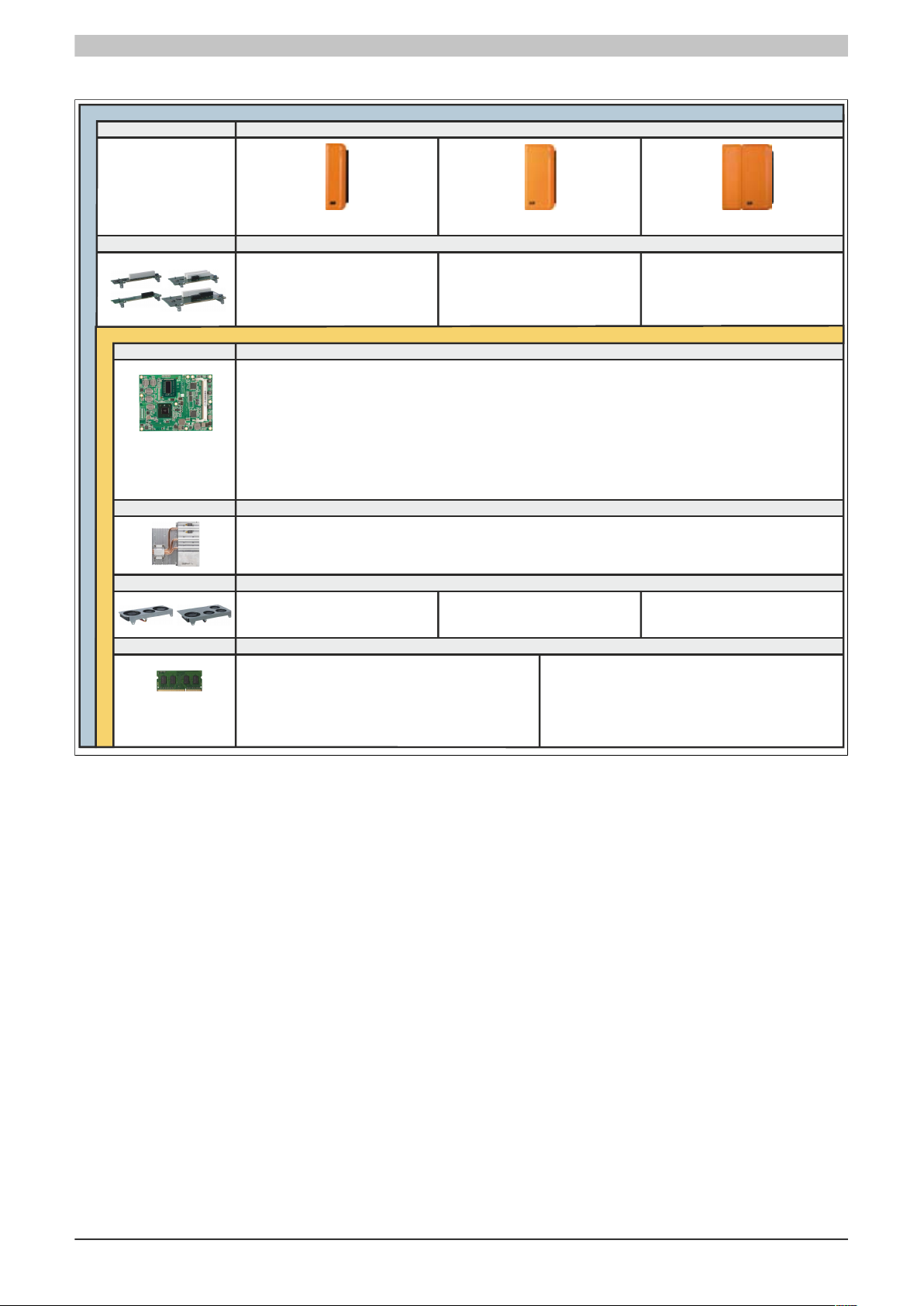
Technical data • Introduction
System unit
Select
1
A system unit consist
s
of a housing and mainboard.
5PC910.SX01-0
0
Bus uni
t
Select
1
5AC901.BX01-0
0
5AC901.BX01-0
1
5PC910.SX02-0
0
5AC901.BX02-0
0
5AC901.BX02-0
1
5AC901.BX02-0
2
5PC910.SX05-0
0
5AC901.BX05-0
0
5AC901.BX05-0
1
5AC901.BX05-0
2
5AC901.BX05-0
3
Configuration - Base system with a fan kit (active)
CPU board
Select
1
Select
1
CPU board / Heat sink / Fan kit / Main memory
Heat sink
5AC901.HS00-00 (5PC900.TS77-0x)
5AC901.HS00-01 (5PC900.TS17-00, -01, -02, -04
)
5AC901.HS00-02 (5PC900.TS17-03)
Select max. 2
Main memory
Fan kit
Select
1
5AC901.FA01-0
0
5AC901.FA02-0
0
5PC900.TS77-0
0
5PC900.TS77-0
1
5PC900.TS77-0
2
5PC900.TS77-0
3
5PC900.TS77-0
4
5PC900.TS77-0
5
5PC900.TS77-0
6
5PC900.TS77-0
7
5PC900.TS77-0
8
5PC900.TS77-0
9
5PC900.TS77-1
0
QM77 CPU boardsHM76 CPU board
s
5AC901.FA05-0
0
5PC900.TS17-0
0
5PC900.TS17-0
4
5PC900.TS17-0
1
5PC900.TS17-0
2
QM170 CPU boardsHM170 CPU board
s
5MMDDR.1024-0
3
5MMDDR.2048-0
3
5MMDDR.4096-0
3
5MMDDR.8192-0
3
5MMDDR.4096-0
4
5MMDDR.8192-0
4
5MMDDR.016G-0
4
QM77/HM76 CPU board
s
QM170/HM170/CM236 CPU board
s
5PC900.TS17-0
3
CM236 CPU board
s
Configuration with a fan kit
Figure 1: Configuration - Base system with a fan kit
28 Automation PC 910 user's manual V1.51
Page 29
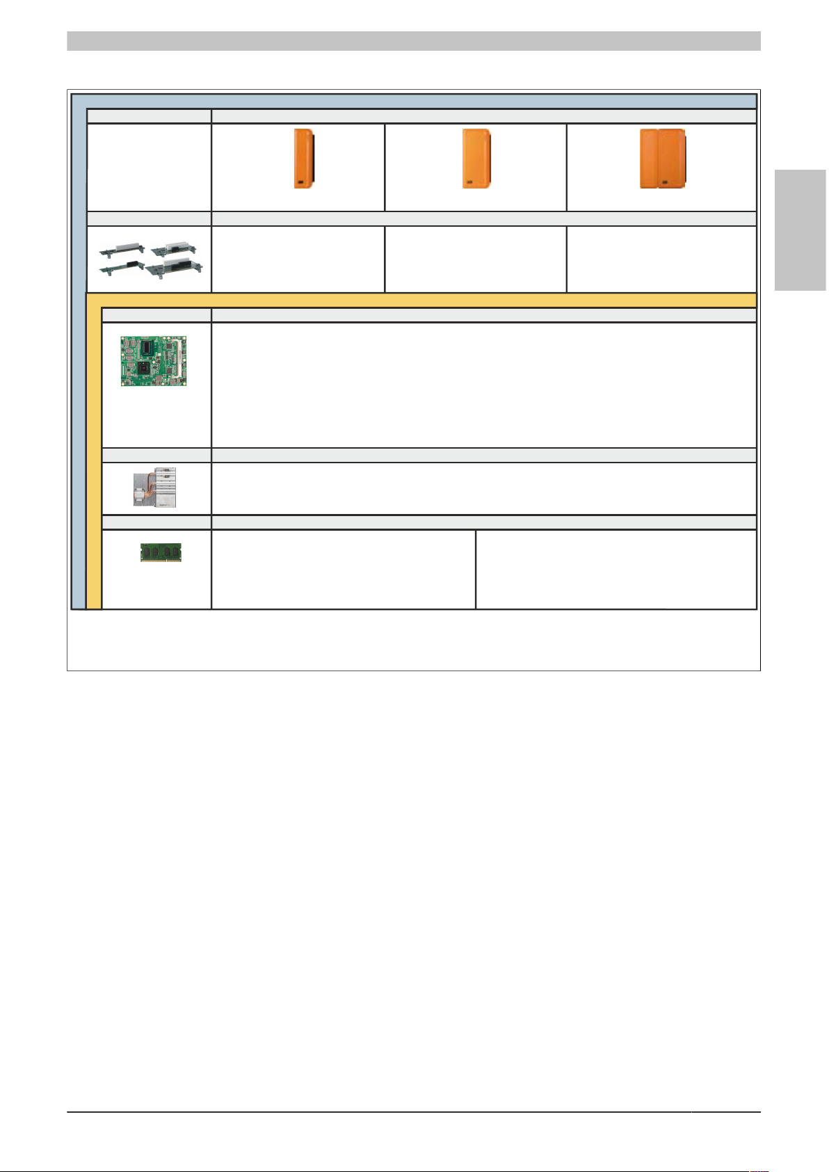
Configuration without a fan kit
1) Main memory frequency of 5PC900.TS77-0x CPU boards limited to 1067 MHz when operating without a fan kit.
2) When operated without a fan ki
t
System unit
Select
1
A system unit consist
s
of a housing and mainboard.
5PC910.SX01-0
0
Bus uni
t
Select
1
5AC901.BX01-0
0
5AC901.BX01-0
1
5PC910.SX02-0
0
5AC901.BX02-0
0
5AC901.BX02-0
1
5AC901.BX02-0
2
5PC910.SX05-0
0
5AC901.BX05-0
0
5AC901.BX05-0
1
5AC901.BX05-0
2
5AC901.BX05-0
3
Configuration - Base system without a fan kit (passive)
CPU board
Select
1
Select
1
Heat sink
5AC901.HS01-00 (5PC900.TS77-0x)
5AC901.HS01-01 (5PC900.TS17-01, -02
)
Select max. 2
Main memory
5MMDDR.1024-0
3
5MMDDR.2048-0
3
5MMDDR.4096-0
3
5MMDDR.8192-0
3
5PC900.TS77-0
1
5PC900.TS77-0
2
5PC900.TS77-0
3
5PC900.TS77-0
4
5PC900.TS77-0
5
5PC900.TS77-0
6
5PC900.TS77-0
7
5PC900.TS77-0
8
5PC900.TS77-0
9
5PC900.TS77-1
0
QM77 CPU boards
HM76 CPU boards
5PC900.TS17-0
1
5PC900.TS17-0
2
HM170 CPU board
s
5MMDDR.4096-0
4
5MMDDR.8192-0
4
5MMDDR.016G-0
4
QM77/HM76 CPU board
s
QM170/HM170/CM236 CPU board
s
1
)
1
)
2
)
●
CPU board 5PC900.TS17-01 is limited to a maximum CPU frequency of 1900 MHz.
●
CPU board 5PC900.TS17-02 is limited to a maximum CPU frequency of 1700 MHz.
CPU board - Heat sink - Main memory
Technical data • Introduction
Chapter 2
Technical data
Figure 2: Configuration - Base system without a fan kit
Automation PC 910 user's manual V1.51 29
Page 30
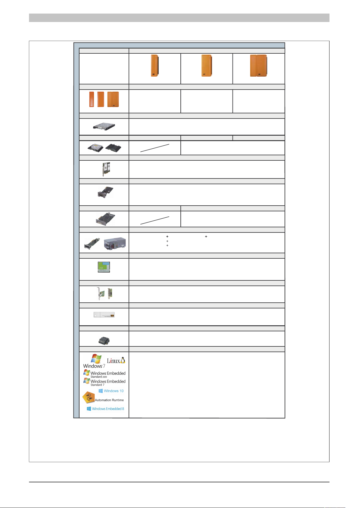
Technical data • Introduction
Front cover
s
Select
1
System unit
Select
1
Monitor/Panel options
Select 1
CFast cards
Operating system
s
Select 1
Select 1
Terminal blocks
Windows 7
5SWWI7.1100-ENG
5SWWI7.1100-GER
5SWWI7.1300-MUL
5SWWI7.1200-ENG
5SWWI7.1200-GER
5SWWI7.1400-MUL
Windows Embedded Standard 7
5SWWI7.1540-ENG
5SWWI7.1640-ENG
5SWWI7.1740-MUL
5SWWI7.1840-MUL
5SWWI7.1849-MUL
Windows Embedded Standard 200
9
5SWWXP.0740-ENG
Automation Runtim
e
0TG1000.0
1
0TG1000.0
2
1TG4600.10-
5
1TG4601.06-
5
IF option
s
Select max. 2 as an option
Power connector
s
0TB103.
9
0TB103.91
A system unit consist
s
of a housing and mainboard.
5AC901.FF01-0
0
5AC901.FF01-0
1
5AC901.FF01-0
2
5AC901.FF01-0
3
5AC901.FF02-0
0
5AC901.FF02-0
1
5AC901.FF02-0
2
5AC901.FF02-0
3
Slide-in compact drives
Select 1
5AC901.LDPO-0
0
5AC901.LSDL-0
0
Select as an option
USB a
cce
ssories
5MMUSB.2048-0
1
5MMUSB.4096-0
1
5MMUSB.032G-0
2
Optional, select
1
Select 1 of ea
ch
UPS
1) The front cover is not included with the system unit and must be ordered separately.
2) Certain limitations must be taken into account when using IF options. For more information
,
see section "Device interfaces" of chapter 2 "Technical data"
.
3) The UPS module can only be operated in the IF option 1 slot.
4) Required = PCIe bu
s
5) Only the following 64-bit operating systems are supported by 5PC900.TS17-0x CPU boards
:
2
)
UPS modul
e
5AC901.IUPS-0
0
5AC901.IUPS-0
1
Battery uni
t
5AC901.BUPS-0
0
5AC901.BUPS-0
1
UPS cable
5CAUPS.0005-0
1
5CAUPS.0010-0
1
3
)
5PC910.SX01-0
0
5PC910.SX02-0
0
5PC910.SX05-0
0
5AC901.FF05-0
0
5AC901.FF05-0
1
5AC901.FF05-0
2
5AC901.FF05-0
3
Slide-in drive
s
Select max. 1
5AC901.SDVW-0
0
5AC901.SSCA-0
0
Select max. 2
Windows X
P
5SWWXP.0600-ENG
5SWWXP.0600-GER
5SWWXP.0600-MUL
RAID
system
Select 1
5ACPCI.RAIC-06 (uses 1 PCI slot)
5MMHDD.0500-0
0
5AC901.CHDD-0
1
5AC901.CSSD-0
3
5AC901.CSSD-0
4
5AC901.CSSD-0
5
5AC901.CSSD-0
6
5AC901.CCFA-0
0
1
)
5AC901.I485-0
0
5AC901.ICAN-0
0
5AC901.ICAN-0
1
5AC901.IHDA-0
0
5AC901.IRDY-0
0
5AC901.IPLK-0
0
5AC901.ISIO-0
0
5AC901.ISRM-0
0
5AC901.IETH-0
0
Windows Embedded 8.1 Industry
5SWWI8.0340-MUL
5SWWI8.0440-MUL
5CFAST.2048-0
0
5CFAST.4096-0
0
5CFAST.8192-0
0
5CFAST.016G-0
0
5CFAST.032G-0
0
5CFAST.032G-1
0
5CFAST.064G-1
0
5CFAST.128G-1
0
5CFAST.256G-1
0
B&R Linux 8 (GNU/Linux)
5SWLIN.0540-MUL
5SWLIN.0640-MUL
5SWLIN.0649-MUL
Windows 1
0
5SWW10.0240-MUL
5SWW10.0249-MUL
5SWW10.0640-MUL
5SWW10.0649-MUL
5SWW10.0740-MUL
5SWW10.0749-MUL
Select 1
PCIe cards
5ACPCE.ETH1-0
0
5ACPCE.ETH4-0
0
4
)
A
cce
ssory and software configuration
5
)
●
Windows 7
●
Windows Embedded Standard 7
●
Windows 10 IoT Enterprise 2015 LTSB
●
Windows 10 IoT Enterprise 2016 LTSB
●
B&R Linux 8
●
B&R Linux 9
5CAUPS.0013-0
1
5CAUPS.0030-0
1
5AC901.LSD3-0
0
5AC901.LSD4-0
0
B&R Linux 9 (GNU/Linux)
5SWLIN.0740-MUL
5SWLIN.0749-MUL
1.5.2 Accessory and software configuration
30 Automation PC 910 user's manual V1.51
Figure 3: Accessory and software configuration
Page 31

Technical data • Complete system
2 Complete system
2.1 Environmental characteristics
2.1.1 Temperature specifications
CPU boards can be combined with various other components such as drives, main memory, additional plug-in
cards, etc. depending on the system unit and fan kit. The many different configurations possible result in varying
maximum ambient temperatures, which can be seen in the following tables in this section.
Information:
The maximum specified ambient temperatures for operation with and without a fan kit have been determined under worst-case conditions. Experience has shown that higher ambient temperatures can
be achieved in typical applications, e.g. in Microsoft Windows. Testing and evaluation in this regard
must be performed on-site by the user in each individual case (temperatures can be read in BIOS or
using the B&R Control Center).
Information regarding worst-case conditions of QM77/HM76 CPU boards
•
Thermal Analysis Tool (TAT V4.3) from Intel for simulating a 100% processor load
•
BurnInTest tool (BurnInTest V4.0 Pro from Passmark Software) for simulating a 100% load on the interface
via loopback adapters (serial interfaces, slide-in drives, USB interfaces, audio outputs)
•
Maximum system expansion and power consumption
Chapter 2
Technical data
Information regarding worst-case conditions for QM170/HM170/CM236 CPU boards
•
Thermal Analysis Tool (TAT V5) from Intel for simulating a 100% processor load
•
BurnInTest tool (BurnInTest V6.0 Pro from PassMark Software) for simulating a 100% load on the interface
via loopback adapters (serial interfaces, slide-in drives, USB interfaces, audio outputs)
•
Maximum system expansion and power consumption
Automation PC 910 user's manual V1.51 31
Page 32
Technical data • Complete system
2.1.1.1 Maximum ambient temperaturefor worst-case operation
Operation with a fan kit on QM77/HM76 CPU boards
Information:
The 5AC901.HS00-00 heat sink must be used when operating the Automation PC 910 with a fan kit.
All values apply to non-condensing operation.
Operation with a fan kit and 5AC901.HS00-00 heat sink
i7
All temperature values in degrees
Celsius (°C) at 500 meters above sea level.
The maximum ambient temperature is
typically derated by 1°C per 1000 meters
starting at 500 meters above sea level.
Maximum ambient temperature
for worst-case operation
What else can also be operated at the max.
ambient temperature, or is there a limitation?
5PC910.SX01-00 ✓ ✓ ✓ ✓ ✓ ✓ ✓ ✓ ✓ ✓ ✓
System units
5PC910.SX02-00 ✓ ✓ ✓ ✓ ✓ ✓ ✓ ✓ ✓ ✓ ✓
5PC910.SX05-00 ✓ ✓ ✓ ✓ ✓ ✓ ✓ ✓ ✓ ✓ ✓
5MMDDR.1024-03 ✓ ✓ ✓ ✓ ✓ ✓ ✓ ✓ ✓ ✓ ✓
Main memory
5MMDDR.2048-03 ✓ ✓ ✓ ✓ ✓ ✓ ✓ ✓ ✓ ✓ ✓
5MMDDR.4096-03 ✓ ✓ ✓ ✓ ✓ ✓ ✓ ✓ ✓ ✓ ✓
5MMDDR.8192-03 ✓ ✓ ✓ ✓ ✓ ✓ ✓ ✓ ✓ ✓ ✓
5AC901.CHDD-00 ✓ 50 50 50 50 50 50 50 50 50 50
5AC901.CHDD-01 ✓ 50 50 50 50 50 50 50 50 50 50
5AC901.CSSD-00 ✓ ✓ ✓ ✓ ✓ ✓ ✓ ✓ ✓ ✓ ✓
5AC901.CSSD-01 ✓ ✓ ✓ ✓ ✓ ✓ ✓ ✓ ✓ ✓ ✓
Slide-in compact
drives
5AC901.CSSD-02 ✓ ✓ ✓ ✓ ✓ ✓ ✓ ✓ ✓ ✓ ✓
5AC901.CSSD-03 ✓ ✓ ✓ ✓ ✓ ✓ ✓ ✓ ✓ ✓ ✓
5AC901.CSSD-04 ✓ ✓ ✓ ✓ ✓ ✓ ✓ ✓ ✓ ✓ ✓
5AC901.CSSD-05 ✓ ✓ ✓ ✓ ✓ ✓ ✓ ✓ ✓ ✓ ✓
5AC901.CSSD-06 ✓ ✓ ✓ ✓ ✓ ✓ ✓ ✓ ✓ ✓ ✓
5AC901.CCFA-00 ✓ ✓ ✓ ✓ ✓ ✓ ✓ ✓ ✓ ✓ ✓
Slide-in drives
5AC901.SDVW-00 40 40 40 40 40 40 40 40 40 40 40
5AC901.SSCA-00
1)
RAID system 5ACPCI.RAIC-06 ✓ ✓ ✓ ✓ ✓ ✓ ✓ ✓ ✓ ✓ ✓
5AC901.I485-00 ✓ ✓ ✓ ✓ ✓ ✓ ✓ ✓ ✓ ✓ ✓
5AC901.ICAN-00 ✓ ✓ ✓ ✓ ✓ ✓ ✓ ✓ ✓ ✓ ✓
5AC901.ICAN-01 ✓ ✓ ✓ ✓ ✓ ✓ ✓ ✓ ✓ ✓ ✓
5AC901.IHDA-00 ✓ ✓ ✓ ✓ ✓ ✓ ✓ ✓ ✓ ✓ ✓
5AC901.ISRM-00 ✓ ✓ ✓ ✓ ✓ ✓ ✓ ✓ ✓ ✓ ✓
Interface options
5AC901.IPLK-00 ✓ ✓ ✓ ✓ ✓ ✓ ✓ ✓ ✓ ✓ ✓
5AC901.IRDY-00 ✓ ✓ ✓ ✓ ✓ ✓ ✓ ✓ ✓ ✓ ✓
5AC901.ISIO-00 ✓ ✓ ✓ ✓ ✓ ✓ ✓ ✓ ✓ ✓ ✓
5AC901.IUPS-00 ✓ ✓ ✓ ✓ ✓ ✓ ✓ ✓ ✓ ✓ ✓
5AC901.IUPS-01 ✓ ✓ ✓ ✓ ✓ ✓ ✓ ✓ ✓ ✓ ✓
5AC901.IETH-00 ✓ ✓ ✓ ✓ ✓ ✓ ✓ ✓ ✓ ✓ ✓
5AC901.LDPO-00 ✓ ✓ ✓ ✓ ✓ ✓ ✓ ✓ ✓ ✓ ✓
Monitor/Panel
options
5AC901.LSDL-00 ✓ ✓ ✓ ✓ ✓ ✓ ✓ ✓ ✓ ✓ ✓
5AC901.LSD3-00 ✓ ✓ ✓ ✓ ✓ ✓ ✓ ✓ ✓ ✓ ✓
5AC901.LSD4-00 ✓ ✓ ✓ ✓ ✓ ✓ ✓ ✓ ✓ ✓ ✓
CFast cards
PCIe cards
5CFAST.xxxx-00 ✓ ✓ ✓ ✓ ✓ ✓ ✓ ✓ ✓ ✓ ✓
5CFAST.xxxx-10 ✓ ✓ ✓ ✓ ✓ ✓ ✓ ✓ ✓ ✓ ✓
5ACPCE.ETH1-00 ✓ ✓ ✓ ✓ ✓ ✓ ✓ ✓ ✓ ✓ ✓
5ACPCE.ETH4-00
1) The max. temperature depends on the slide-in compact drive being used.
Table 5: Ambient temperature with a fan kit
3615QEi73612QEi73555LEi73517UEi53610MEi33120MEi33217UECM847ECM827ECM1020ECM1047UE
5PC900.TS77-00
5PC900.TS77-01
5PC900.TS77-02
5PC900.TS77-03
5PC900.TS77-04
5PC900.TS77-05
5PC900.TS77-06
5PC900.TS77-07
5PC900.TS77-08
5PC900.TS77-09
50 55 55 55 55 55 55 55 55 55 55
- - - - - - - - - - -
✓ ✓ ✓ ✓ ✓ ✓ ✓ ✓ ✓ ✓ ✓
5PC900.TS77-10
Location of sensor(s)
Power
supply
-
Slide-in compact drive
Slide-
in drive
-
Interface option
Monitor/
Panel option
-
-
32 Automation PC 910 user's manual V1.51
Page 33
Technical data • Complete system
Operation without a fan kit on QM77/HM76 CPU boards
Information:
The 5PC900.TS77-00 CPU board cannot be operated without a fan kit.
The 5AC901.HS01-00 heat sink must be used when operating the Automation PC 910 without a fan kit.
All values apply to non-condensing operation.
Operation without a fan kit and with 5AC901.HS01-00 heat sink
i7
All temperature values in degrees
Celsius (°C) at 500 meters above sea level.
The maximum ambient temperature is
typically derated by 1°C per 1000 meters
starting at 500 meters above sea level.
Maximum ambient temperature
for typical operation
What else can also be operated at the max.
ambient temperature, or is there a limitation?
5PC910.SX01-00 - ✓ ✓ ✓ ✓ ✓ ✓ ✓ ✓ ✓ ✓
System units
5PC910.SX02-00 - ✓ ✓ ✓ ✓ ✓ ✓ ✓ ✓ ✓ ✓
5PC910.SX05-00 - ✓ ✓ ✓ ✓ ✓ ✓ ✓ ✓ ✓ ✓
5MMDDR.1024-03 - ✓ ✓ ✓ ✓ ✓ ✓ ✓ ✓ ✓ ✓
Main memory
5MMDDR.2048-03 - ✓ ✓ ✓ ✓ ✓ ✓ ✓ ✓ ✓ ✓
5MMDDR.4096-03 - ✓ ✓ ✓ ✓ ✓ ✓ ✓ ✓ ✓ ✓
5MMDDR.8192-03 - ✓ ✓ ✓ ✓ ✓ ✓ ✓ ✓ ✓ ✓
5AC901.CHDD-00 - ✓ ✓ 45 ✓ ✓ 45 45 45 ✓ 45
5AC901.CHDD-01 - ✓ ✓ 45 ✓ ✓ 45 45 45 ✓ 45
5AC901.CSSD-00 - ✓ ✓ ✓ ✓ ✓ ✓ ✓ ✓ ✓ ✓
5AC901.CSSD-01 - ✓ ✓ ✓ ✓ ✓ ✓ ✓ ✓ ✓ ✓
Slide-in compact
drives
5AC901.CSSD-02 - ✓ ✓ ✓ ✓ ✓ ✓ ✓ ✓ ✓ ✓
5AC901.CSSD-03 - ✓ ✓ ✓ ✓ ✓ ✓ ✓ ✓ ✓ ✓
5AC901.CSSD-04 - ✓ ✓ ✓ ✓ ✓ ✓ ✓ ✓ ✓ ✓
5AC901.CSSD-05 - ✓ ✓ ✓ ✓ ✓ ✓ ✓ ✓ ✓ ✓
5AC901.CSSD-06 - ✓ ✓ ✓ ✓ ✓ ✓ ✓ ✓ ✓ ✓
5AC901.CCFA-00 - ✓ ✓ ✓ ✓ ✓ ✓ ✓ ✓ ✓ ✓
Slide-in drives
5AC901.SDVW-00 - 25 25 25 25 25 25 25 25 25 25
5AC901.SSCA-00
1)
RAID system 5ACPCI.RAIC-06 - ✓ ✓ ✓ ✓ ✓ ✓ ✓ ✓ ✓ ✓
5AC901.I485-00 - ✓ ✓ ✓ ✓ ✓ ✓ ✓ ✓ ✓ ✓
5AC901.ICAN-00 - ✓ ✓ ✓ ✓ ✓ ✓ ✓ ✓ ✓ ✓
5AC901.ICAN-01 - ✓ ✓ ✓ ✓ ✓ ✓ ✓ ✓ ✓ ✓
5AC901.IHDA-00 - ✓ ✓ 40 ✓ ✓ 40 40 40 ✓ 40
5AC901.ISRM-00 - ✓ ✓ ✓ ✓ ✓ ✓ ✓ ✓ ✓ ✓
Interface options
5AC901.IPLK-00 - ✓ ✓ ✓ ✓ ✓ ✓ ✓ ✓ ✓ ✓
5AC901.IRDY-00 - ✓ ✓ ✓ ✓ ✓ ✓ ✓ ✓ ✓ ✓
5AC901.ISIO-00 - ✓ ✓ ✓ ✓ ✓ ✓ ✓ ✓ ✓ ✓
5AC901.IUPS-00 - ✓ ✓ ✓ ✓ ✓ ✓ ✓ ✓ ✓ ✓
5AC901.IUPS-01 - ✓ ✓ ✓ ✓ ✓ ✓ ✓ ✓ ✓ ✓
5AC901.IETH-00 - ✓ ✓ ✓ ✓ ✓ ✓ ✓ ✓ ✓ ✓
5AC901.LDPO-00 - ✓ ✓ ✓ ✓ ✓ ✓ ✓ ✓ ✓ ✓
Monitor/Panel
options
5AC901.LSDL-00 - ✓ ✓ ✓ ✓ ✓ ✓ ✓ ✓ ✓ ✓
5AC901.LSD3-00 - ✓ ✓ ✓ ✓ ✓ ✓ ✓ ✓ ✓ ✓
5AC901.LSD4-00 - ✓ ✓ ✓ ✓ ✓ ✓ ✓ ✓ ✓ ✓
CFast cards
PCIe cards
5CFAST.xxxx-00 - ✓ ✓ ✓ ✓ ✓ ✓ ✓ ✓ ✓ ✓
5CFAST.xxxx-10 - ✓ ✓ ✓ ✓ ✓ ✓ ✓ ✓ ✓ ✓
5ACPCE.ETH1-00 - ✓ ✓ ✓ ✓ ✓ ✓ ✓ ✓ ✓ ✓
5ACPCE.ETH4-00
1) The max. temperature depends on the slide-in compact drive being used.
Table 6: Ambient temperature without a fan kit
3615QEi73612QEi73555LEi73517UEi53610MEi33120MEi33217UECM847ECM827ECM1020ECM1047UE
5PC900.TS77-00
5PC900.TS77-01
5PC900.TS77-02
5PC900.TS77-03
5PC900.TS77-04
5PC900.TS77-05
5PC900.TS77-06
5PC900.TS77-07
5PC900.TS77-08
5PC900.TS77-09
- 35 40 50 35 35 50 50 50 35 50
- - - - - - - - - - -
✓ ✓ ✓ ✓ ✓ ✓ ✓ ✓ ✓ ✓
-
5PC900.TS77-10
Location of sensor(s)
Power
supply
-
Slide-in compact drive
Slide-
in drive
-
Interface option
Monitor/
Panel option
-
-
Chapter 2
Technical data
Automation PC 910 user's manual V1.51 33
Page 34
Technical data • Complete system
Operation of QM170/HM170/CM236 CPU boards with a fan kit
Information:
Heat sink 5AC901.HS00-01 or 5AC901.HS00-02 must be used when operating the Automation PC 910
with a fan kit.
All values apply to non-condensing operation.
Operation with a fan kit and heat sink
5AC901.HS00-01/5AC901.HS00-02
i5 6440EQ i3 6100E G3900E E3-1515MV5 i7 6820EQ
All temperature values in degrees
Celsius (°C) at 500 meters above sea level.
@2700
The maximum ambient temperature is typically derated by
1°C per 1000 meters starting at 500 meters above sea level.
Maximum ambient temperature for worst-case operation 50 55 60 50 50
What else can also be operated at the max.
ambient temperature, or is there a limitation?
5PC910.SX01-00 ✓ ✓ ✓ ✓ ✓
System units
5PC910.SX02-00 ✓ ✓ ✓ ✓ ✓
5PC910.SX05-00 ✓ ✓ ✓ ✓ ✓
5MMDDR.4096-04
Main memory
5MMDDR.8192-04
5MMDDR.016G-04
5AC901.CHDD-00 ✓ 50 50 ✓ ✓
5AC901.CHDD-01 ✓ 50 50 ✓ ✓
5AC901.CSSD-00 ✓ ✓ ✓ ✓ ✓
5AC901.CSSD-01 ✓ ✓ ✓ ✓ ✓
Slide-in compact
drives
5AC901.CSSD-02 ✓ ✓ ✓ ✓ ✓
5AC901.CSSD-03 ✓ ✓ ✓ ✓ ✓
5AC901.CSSD-04 ✓ ✓ ✓ ✓ ✓
5AC901.CSSD-05 ✓ ✓ ✓ ✓ ✓
5AC901.CSSD-06 ✓ ✓ ✓ ✓ ✓
5AC901.CCFA-00 ✓ ✓ ✓ ✓ ✓
Slide-in drives
5AC901.SDVW-00 40 40 40 40 40
5AC901.SSCA-00
1)
RAID system 5ACPCI.RAIC-06 ✓ ✓ ✓ ✓ ✓
5AC901.I485-00 ✓ ✓ ✓ ✓ ✓
5AC901.ICAN-00 ✓ ✓ ✓ ✓ ✓
5AC901.ICAN-01 ✓ ✓ ✓ ✓ ✓
5AC901.IHDA-00 ✓ ✓ ✓ ✓ ✓
5AC901.ISRM-00 ✓ ✓ ✓ ✓ ✓
Interface options
5AC901.IPLK-00 ✓ ✓ ✓ ✓ ✓
5AC901.IRDY-00 ✓ ✓ ✓ ✓ ✓
5AC901.ISIO-00 ✓ ✓ ✓ ✓ ✓
5AC901.IUPS-00 ✓ ✓ ✓ ✓ ✓
5AC901.IUPS-01 ✓ ✓ ✓ ✓ ✓
5AC901.IETH-00 ✓ ✓ ✓ ✓ ✓
5AC901.LDPO-00 ✓ ✓ ✓ ✓ ✓
Monitor/Panel
options
5AC901.LSDL-00 ✓ ✓ ✓ ✓ ✓
5AC901.LSD3-00 ✓ ✓ ✓ ✓ ✓
5AC901.LSD4-00 ✓ ✓ ✓ ✓ ✓
CFast cards
PCIe cards
5CFAST.xxxx-00 ✓ ✓ ✓ ✓ ✓
5CFAST.xxxx-10 ✓ ✓ ✓ ✓ ✓
5ACPCE.ETH1-00 ✓ ✓ ✓ ✓ ✓
5ACPCE.ETH4-00
1) The max. temperature depends on the slide-in compact drive being used.
Table 7: Ambient temperature with a fan kit
5PC900.TS17-00
5PC900.TS17-01
✓ ✓ ✓ ✓ ✓
✓ ✓ ✓ ✓ ✓
✓ ✓ ✓ ✓ ✓
- - - - -
✓ ✓ ✓ ✓ ✓
@2400
5PC900.TS17-02
5PC900.TS17-03
5PC900.TS17-04
Location of sensor(s)
Power
supply
-
Slide-in compact drive
Slide-
in drive
-
Interface option
Monitor/
Panel option
-
-
34 Automation PC 910 user's manual V1.51
Page 35
Technical data • Complete system
Operation of QM170/HM170/CM236 CPU boards without a fan kit
Information:
CPU boards 5PC900.TS17-00, 5PC900.TS17-03 and 5PC900.TS17-04 cannot be operated without a fan
kit.
Heat sink 5AC901.HS01-01 must be used when operating the Automation PC 910 without a fan kit.
All values apply to non-condensing operation.
Operation without a fan kit and
with 5AC901.HS01-01 heat sink
i5 6440EQ i3 6100E G3900E E3-1515MV5 i7 6820EQ
All temperature values in degrees
Celsius (°C) at 500 meters above sea level.
@1900
The maximum ambient temperature is typically derated by
1°C per 1000 meters starting at 500 meters above sea level.
Maximum ambient temperature for worst-case operation - 45 55 - -
What else can also be operated at the max.
ambient temperature, or is there a limitation?
5PC910.SX01-00 - ✓ ✓ - -
System units
Main memory
Slide-in compact
drives
Slide-in drives
RAID system 5ACPCI.RAIC-06 - ✓ ✓ - -
Interface options
Monitor/Panel
options
CFast cards
PCIe cards
1) The max. temperature depends on the slide-in compact drive being used.
5PC910.SX02-00 - ✓ ✓ - 5PC910.SX05-00 - ✓ ✓ - 5MMDDR.4096-04 - ✓ ✓ - 5MMDDR.8192-04 - ✓ ✓ - 5MMDDR.016G-04 - ✓ ✓ - 5AC901.CHDD-00 - ✓ 45 - 5AC901.CHDD-01 - ✓ 45 - 5AC901.CSSD-00 - ✓ ✓ - 5AC901.CSSD-01 - ✓ ✓ - 5AC901.CSSD-02 - ✓ ✓ - 5AC901.CSSD-03 - ✓ ✓ - 5AC901.CSSD-04 - ✓ ✓ - 5AC901.CSSD-05 - ✓ ✓ - 5AC901.CSSD-06 - ✓ ✓ - 5AC901.CCFA-00 - ✓ ✓ - 5AC901.SDVW-00 - 25 25 - 5AC901.SSCA-00
5AC901.I485-00 - ✓ ✓ - 5AC901.ICAN-00 - ✓ ✓ - 5AC901.ICAN-01 - ✓ ✓ - 5AC901.IHDA-00 - 40 40 - 5AC901.ISRM-00 - ✓ ✓ - 5AC901.IPLK-00 - ✓ ✓ - 5AC901.IRDY-00 - ✓ ✓ - 5AC901.ISIO-00 - ✓ ✓ - 5AC901.IUPS-00 - ✓ ✓ - 5AC901.IUPS-01 - ✓ ✓ - 5AC901.IETH-00 - ✓ ✓ - 5AC901.LDPO-00 - ✓ ✓ - 5AC901.LSDL-00 - ✓ ✓ - 5AC901.LSD3-00 - ✓ ✓ - 5AC901.LSD4-00 - ✓ ✓ - 5CFAST.xxxx-00 - ✓ ✓ - 5CFAST.xxxx-10 - ✓ ✓ - 5ACPCE.ETH1-00 - ✓ ✓ - 5ACPCE.ETH4-00
1)
Table 8: Ambient temperature without a fan kit
5PC900.TS17-00
5PC900.TS17-01
- - - - -
✓ ✓
-
@1700
5PC900.TS17-02
5PC900.TS17-03
- -
5PC900.TS17-04
Chapter 2
Location of sensor(s)
Power
supply
-
Slide-in compact drive
Slide-
in drive
-
Interface option
Monitor/
Panel option
-
-
Technical data
Automation PC 910 user's manual V1.51 35
Page 36

Technical data • Complete system
2.1.1.1.1 How to determine the maximum ambient temperature
1. Select the CPU board (operation with or without a fan kit).
2. The "Maximum ambient temperature" row shows the maximum ambient temperature for the complete system,
including the respective CPU board.
Information:
Maximum temperature data is for operation at 500 meters. The maximum ambient temperature is
typically derated by 1°C per 1000 meters (starting at 500 meters above sea level).
3. Incorporating additional drives, main memory, interface options, etc. can change the temperature limits of
an APC910 system.
If there is a "✓" next to the component, it can be used at the maximum ambient temperature of the complete system
without problems.
If there is a specific temperature next to the component, for example "45", then the ambient temperature of the
complete APC910 system is not permitted to exceed this temperature.
2.1.1.2 Minimum ambient temperaturefor worst-case operation
For systems containing the following components, the minimum ambient temperature for non-condensing operation
is +5°C: 5AC901.SDVW-00.
If none of these components are used, then the minimum ambient temperature for non-condensing operation is 0°C.
36 Automation PC 910 user's manual V1.51
Page 37
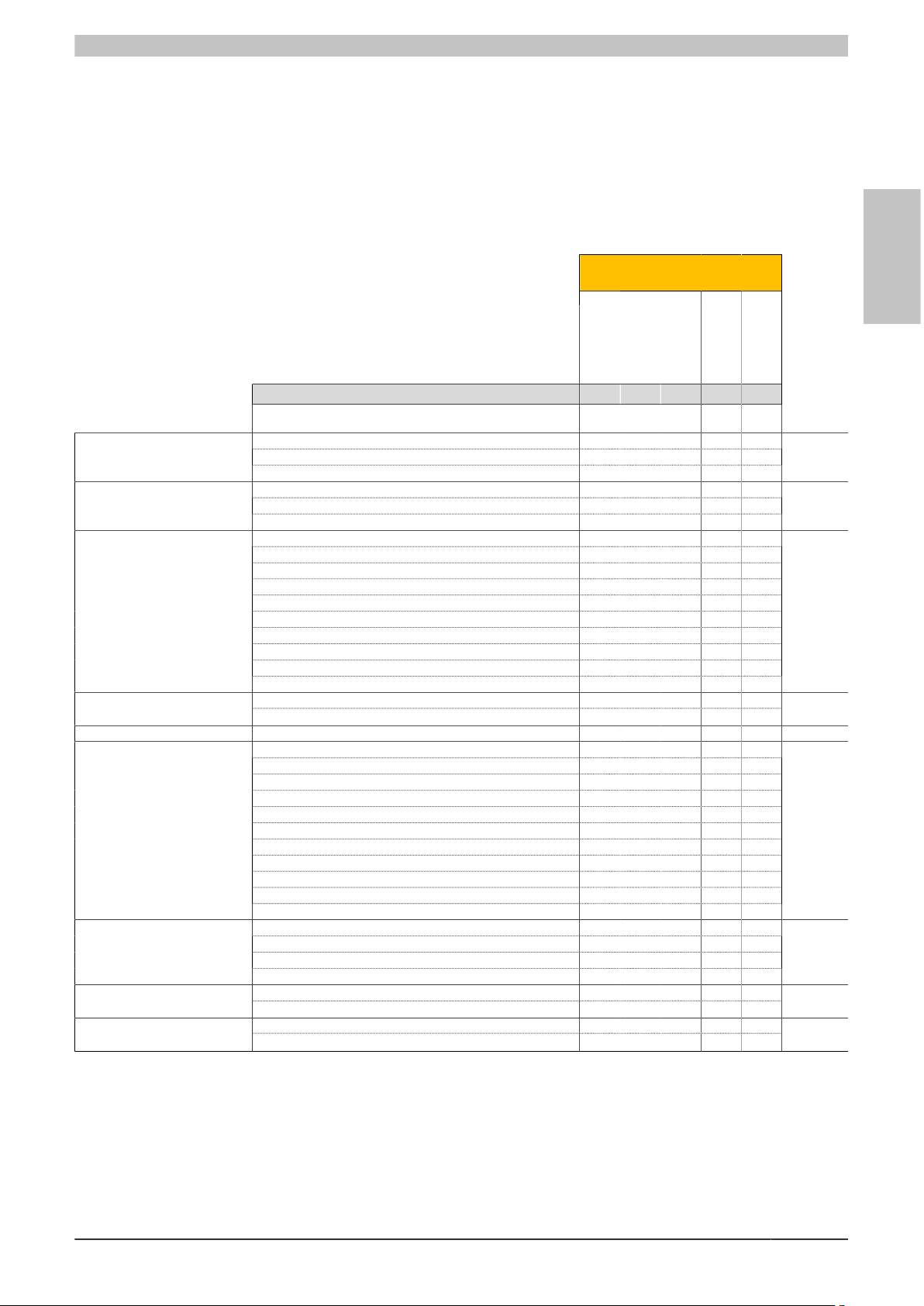
2.1.1.3 Maximum ambient temperature for typical operation
Information regarding typical conditions
•
The total power of all USB interfaces on the system unit is limited to 20 W.
•
2x Gigabit Ethernet
•
No permanent 100% processor load and graphics load
•
The power consumption of the entire system is limited to 55 W or 60 W. For information about the power
consumption of individual components, see 2.2.1 "Power management".
All temperature values in degrees
Celsius (°C) at 500 m above sea level.
The maximum ambient temperature is typically derated by
1°C per 1000 meters starting at 500 meters above sea level.
Maximum ambient temperature for typical operation - 50 60 - -
What else can also be operated at the max.
ambient temperature, or is there a limitation?
5PC910.SX01-00 - ✓ ✓ - -
System units
Main memory
Slide-in compact
Drives
Slide-in drives
RAID system 5ACPCI.RAIC-06 - ✓ 50 - -
Interface options
Monitor/Panel
Options
CFast cards
PCIe cards
1) The max. temperature depends on the slide-in compact drive being used.
5PC910.SX02-00 - ✓ ✓ - 5PC910.SX05-00 - ✓ ✓ - 5MMDDR.4096-04 - ✓ ✓ - 5MMDDR.8192-04 - ✓ ✓ - 5MMDDR.016G-04 - ✓ ✓ - 5AC901.CHDD-00 - ✓ 50 - 5AC901.CHDD-01 - ✓ 50 - 5AC901.CSSD-00 - ✓ ✓ - 5AC901.CSSD-01 - ✓ ✓ - 5AC901.CSSD-02 - ✓ ✓ - 5AC901.CSSD-03 - ✓ ✓ - 5AC901.CSSD-04 - ✓ ✓ - 5AC901.CSSD-05 - ✓ ✓ - 5AC901.CSSD-06 - ✓ ✓ - 5AC901.CCFA-00 - ✓ ✓ - 5AC901.SDVW-00 - 25 25 - 5AC901.SSCA-00
5AC901.I485-00 - ✓ ✓ - 5AC901.ICAN-00 - ✓ ✓ - 5AC901.ICAN-01 - ✓ ✓ - 5AC901.IHDA-00 - 40 40 - 5AC901.ISRM-00 - ✓ ✓ - 5AC901.IPLK-00 - ✓ ✓ - 5AC901.IRDY-00 - ✓ ✓ - 5AC901.ISIO-00 - ✓ ✓ - 5AC901.IUPS-00 - ✓ ✓ - 5AC901.IUPS-01 - ✓ ✓ - 5AC901.IETH-00 - ✓ ✓ - 5AC901.LDPO-00 - ✓ ✓ - 5AC901.LSDL-00 - ✓ ✓ - 5AC901.LSD3-00 - ✓ ✓ - 5AC901.LSD4-00 - ✓ ✓ - 5CFAST.xxxx-00 - ✓ ✓ - 5CFAST.xxxx-10 - ✓ ✓ - 5ACPCE.ETH1-00 - ✓ ✓ - 5ACPCE.ETH4-00
1)
Table 9: Ambient temperature without a fan kit
Technical data • Complete system
Operation without a fan kit and
with 5AC901.HS01-01 heat sink
i5 6440EQ i3 6100E G3900E E3-1515MV5 i7 6820EQ
@1900
@1700
5PC900.TS17-00
5PC900.TS17-01
5PC900.TS17-02
5PC900.TS17-03
5PC900.TS17-04
- - - - -
✓ ✓
-
- -
Chapter 2
Location of sensor(s)
Power
supply
-
Slide-in compact drive
Slide-
in drive
-
Interface option
Monitor/
Panel option
-
-
Technical data
Automation PC 910 user's manual V1.51 37
Page 38

Technical data • Complete system
2.1.1.4 Temperature monitoring
Sensors monitor temperature values at various locations in the APC910 device. The location of these temperature
sensors is illustrated in Fig. 4 " Temperature sensor locations" on page 39. The values listed in Tab. 10 "Tem-
perature sensor locations" on page 39 represent the defined maximum temperature for this measurement point.
An alarm is not triggered if this temperature is exceeded.
These temperatures 4) can be read in various ways in approved operating systems:
•
BIOS
•
B&R Control Center
•
B&R ADI Development Kit
•
B&R ADI .NET SDK
•
B&R HMI Service Center
•
B&R HMI Diagnose
•
B&R PVI ADI line
•
B&R ADI SNMP Agent
•
Automation Runtime Library
5)
5)
5)
5)
5)
5)
5)
5)
In addition, the CFast cards available from B&R for APC910 systems are equipped with S.M.A.R.T, or Self-Monitoring, Analysis and Reporting Technology. This makes it possible to read various parameters such as temperature
using software (e.g. HDD Thermometer, a freeware program) on approved Microsoft operating systems.
For applications that do not run in approved operating systems, temperatures can be evaluated using the B&R
implementation guide. In addition to the implementation guide, programs in MS-DOS are also available.
4)
The temperature measured approximates the immediate ambient temperature but may also be influenced by neighboring components.
5)
Drivers for approved operating systems can be downloaded at no cost from the Downloads section of the B&R website (www.br-automation.com).
38 Automation PC 910 user's manual V1.51
Page 39
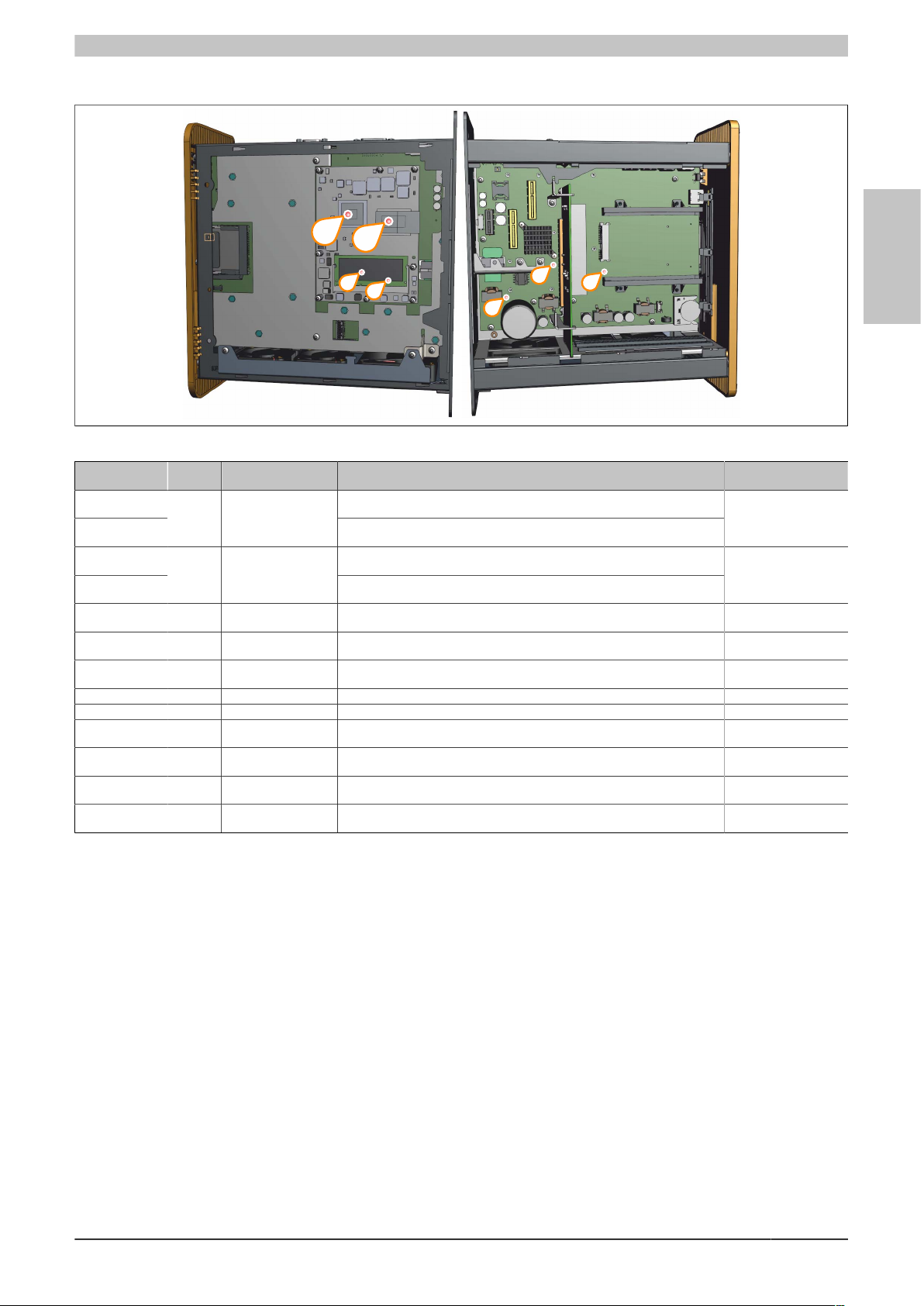
Technical data • Complete system
A/B
D
E
C
J
K
A/B
2.1.1.5 Temperature sensor positions
Figure 4: Temperature sensor locations
ADI sensors Position Measurement point
CPU board
Sensor 1
CPU board
Sensor 2
CPU board
Sensor 1
CPU board
Sensor 2
System unit
Sensor 3
System unit
Sensor 1
System unit
Sensor 2
Slide-in drive 1 F Slide-in drive 1 Temperature of slide-in drive 1 (sensor integrated in the slide-in slot) Depends on the drive
Slide-in drive 2 G Slide-in drive 2 Temperature of slide-in drive 2 (sensor integrated in the slide-in slot) Depends on the drive
- H Interface option
Display Link
Sensor
CPU board
Sensor 3
CPU board
Sensor 4
1) A temperature sensor is currently not integrated in the interface options.
2) A valid temperature is only provided if the module is connected and equipped with a temperature sensor. Otherwise, the value 0 is output in the ADI Control
Center and BIOS; an alarm is also output in the ADI Control Center.
for
A CPU
B Board controller
C Main memory Temperature of the main memory area (sensor integrated on the mainboard) 75°C
D Board power supply Temperature of the board power supply (sensor on the mainboard) 90°C
E Slide-in compact Temperature of the slide-in compact drive area (sensor on the mainboard) Depends on the drive
I Monitor/Panel option Temperature of the monitor/panel option (sensor integrated on the monitor/panel
J SO-DIMM 1
K SO-DIMM 2
2)
2)
Measurement Max. specified
Temperature of the processor (sensor integrated in the processor) for TS17.
Temperature of the processor (sensor integrated in the processor) for TS77.
Temperature of the board controller (sensor integrated on the CPU board) TS77.
Temperature of the board controller (sensor integrated on the CPU board) TS17.
1)
Temperature of the interface option (sensor integrated on the interface option) Depends on the
option)
Temperature of main memory 1 (sensor integrated on main memory 1). 85°C
Temperature of main memory 2 (sensor integrated on main memory 2). 85°C
Table 10: Temperature sensor locations
95°C
95°C
interface option
Depends on the mon-
itor/panel option
Chapter 2
Technical data
Automation PC 910 user's manual V1.51 39
Page 40

Technical data • Complete system
2.1.1.6 Fan control
The MTCX constantly monitors the temperature using temperature sensors, which directly determines how the
fans are controlled. Their speed depends on the measured temperature. Limit values may depend on the MTCX
firmware version being used.
Position Measurement point for Startup temperature Max. fan speed at:
1) A temperature sensor is currently not integrated in the interface options.
CPU for TS17
A
Board controller for TS77
CPU for TS77
B
Board controller for TS17
C Main memory 60°C 76°C
D Board power supply 70°C 86°C
E Slide-in compact 60°C 76°C
F Slide-in drive 1 5AC901.SDVW-00: 44°C, 5AC901.SSCA-00: 55°C 5AC901.SDVW-00: 60°C, 5AC901.SSCA-00: 71°C
G Slide-in drive 2 5AC901.SDVW-00: 44°C, 5AC901.SSCA-00: 55°C 5AC901.SDVW-00: 60°C, 5AC901.SSCA-00: 71°C
H Interface option
I Monitor/Panel option 5AC901.LDPO-00: 60°C ; 5AC901.LSDL-00: 60°C;
J SO-DIMM 1 60°C 76°C
K SO-DIMM 2 60°C 76°C
1)
65°C 81°C
65°C 81°C
- -
5AC901.LSD3-00: 60°C; 5AC901.LSD4-00: 60°C
5AC901.LDPO-00: 76°C ; 5AC901.LSDL-00: 76°C;
5AC901.LSD3-00: 76°C; 5AC901.LSD4-00: 76°C
Table 11: Temperature sensor locations
Once the startup temperature is reached, the device is started at the minimum fan speed. The maximum fan speed
is reached at a startup temperature of 16°C. The fan speed in this area is controlled depending on the temperature.
Example with slide-in drive 5AC901.SDVW-00: 44°C + 16°C = 60°C --> Maximum fan speed
The fans will only be shut off again if the evaluation temperature is more than 6°C below the switch-on temperature
for a period of 4 hours (overshoot time).
40 Automation PC 910 user's manual V1.51
Page 41
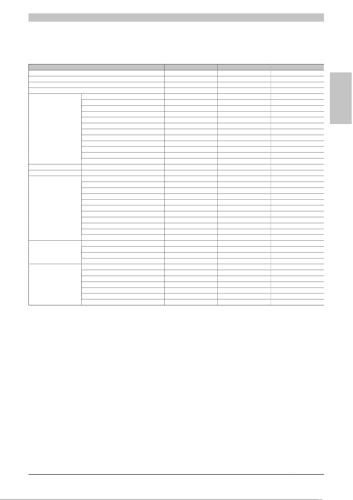
Technical data • Complete system
2.1.2 Humidity specifications
The following table shows the minimum and maximum relative humidity values (non-condensing) of the individual
components that are relevant to the humidity limitations of the complete system. The lowest and highest common
values are always used for this determination.
Component Operation Storage Transport
System units (all models) 5 to 90% 5 to 95% 5 to 95%
QM77/HM76 CPU boards 10 to 90% 5 to 95% 5 to 95%
QM170/HM170/CM236 CPU boards 10 to 90% 5 to 95% 5 to 95%
Main memory for CPU boards 10 to 90% 5 to 95% 5 to 95%
Slide-in compact drives
Slide-in drives 5AC901.SDVW-00 8 to 80% 5 to 95% 5 to 95%
RAID system 5ACPCI.RAIC-06 8 to 90% 5 to 95% 5 to 95%
Interface options
Monitor/Panel options
Accessories
5AC901.CHDD-00 5 to 95% 5 to 95% 5 to 95%
5AC901.CHDD-01 8 to 90% 5 to 95% 5 to 95%
5AC901.CSSD-00 5 to 95% 5 to 95% 5 to 95%
5AC901.CSSD-01 5 to 95% 5 to 95% 5 to 95%
5AC901.CSSD-02 5 to 95% 5 to 95% 5 to 95%
5AC901.CSSD-03 ≤ Rev. C0 8 to 90% 8 to 95% 8 to 95%
5AC901.CSSD-03 ≥ Rev. D0 5 to 90% 5 to 95% 5 to 95%
5AC901.CSSD-04 ≤ Rev. C0 8 to 90% 8 to 95% 8 to 95%
5AC901.CSSD-04 ≥ Rev. D0 5 to 90% 5 to 95% 5 to 95%
5AC901.CSSD-05 5 to 90% 5 to 95% 5 to 95%
5AC901.CSSD-06 5 to 90% 5 to 95% 5 to 95%
5AC901.CCFA-00 5 to 90% 5 to 95% 5 to 95%
5AC901.I485-00 5 to 90% 5 to 95% 5 to 95%
5AC901.ICAN-00 5 to 90% 5 to 95% 5 to 95%
5AC901.ICAN-01 5 to 90% 5 to 95% 5 to 95%
5AC901.IETH-00 5 to 90% 5 to 95% 5 to 95%
5AC901.IHDA-00 5 to 90% 5 to 95% 5 to 95%
5AC901.ISRM-00 5 to 90% 5 to 95% 5 to 95%
5AC901.IPLK-00 5 to 90% 5 to 95% 5 to 95%
5AC901.IRDY-00 5 to 90% 5 to 95% 5 to 95%
5AC901.ISIO-00 5 to 90% 5 to 95% 5 to 95%
5AC901.IUPS-00 5 to 90% 5 to 95% 5 to 95%
5AC901.IUPS-01 5 to 90% 5 to 95% 5 to 95%
5AC901.LDPO-00 5 to 90% 5 to 95% 5 to 95%
5AC901.LSDL-00 5 to 90% 5 to 95% 5 to 95%
5AC901.LSD3-00 5 to 90% 5 to 95% 5 to 95%
5AC901.LSD4-00 5 to 90% 5 to 95% 5 to 95%
5MMUSB.2048-01 USB flash drive 10 to 90% 5 to 90% 5 to 90%
5MMUSB.4096-01 USB flash drive 10 to 90% 5 to 90% 5 to 90%
5CFAST.xxxx-00 CFast cards Max. 85% Max. 85% Max. 85%
5CFAST.xxxx-10 CFast cards 10 to 95% 10 to 95% 10 to 95%
5MD900.USB2-02 USB media drive 20 to 80% 5 to 90% / 5 to 95% 5 to 90% / 5 to 95%
PCIe card 5ACPCE.ETH1-00 5 to 90% 5 to 95% 5 to 95%
PCIe card 5ACPCE.ETH4-00 5 to 90% 5 to 95% 5 to 95%
Table 12: Overview of humidity specifications for individual components
Chapter 2
Technical data
The specifications listed correspond to the relative humidity (non-condensing) at an ambient temperature of 30°C.
For more detailed information about specific temperature-dependent humidity values, see the technical data for
the individual components.
Automation PC 910 user's manual V1.51 41
Page 42
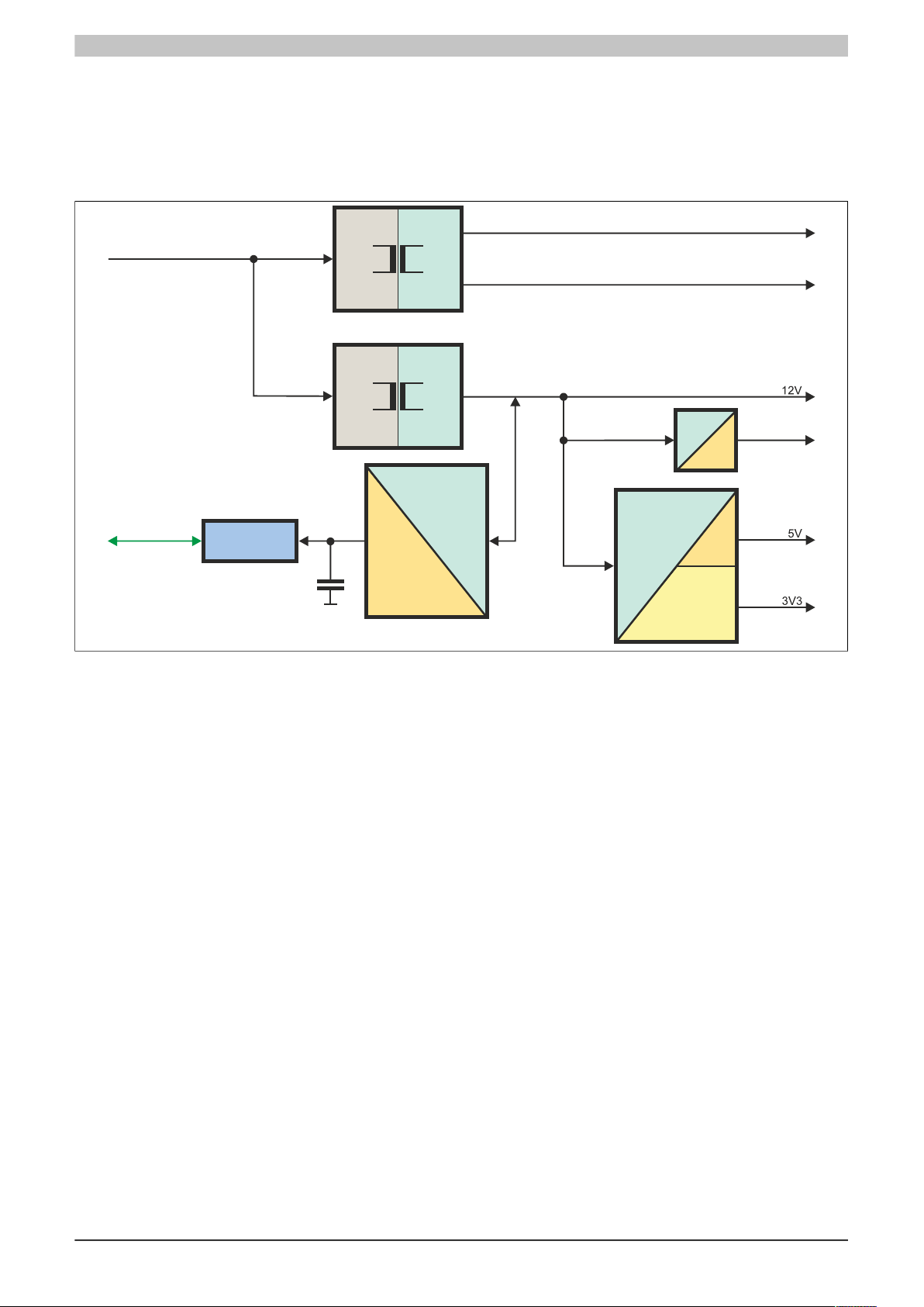
Technical data • Complete system
Supply voltage
+24 VDC
Buffer capacitor
Electrically
isolated
UPS battery
UPS IF option
(optional)
3V3 standby
5 V standby
Electrically
isolated
-12 V
-12 V
12 V
12 V
3V3
5 V
12 V
12 - 50 V
12 V
24 V
24 V
2.2 Electrical characteristics
2.2.1 Power management
2.2.1.1 Power supply - Block diagram
The following block diagram illustrates the simplified structure of the APC910 voltage supply for system units.
Figure 5: Voltage supply for system units
42 Automation PC 910 user's manual V1.51
Page 43
Technical data • Complete system
2.2.1.2 Power calculation with 5PC910.SX01-00
Information:
The power supply's maximum total power of 130 watts must not be exceeded.
Information:
All values are specified in watts.
The values specified for the producers are maximum values. The values
for the consumers are average maximum values, but not peak values.
CPU board, permanent consumers 53 43 33 25 43 43 25 25 25
1024 MB RAM, each 2 W, max. 2 pcs.
2048 MB RAM, each 2.5 W, max. 2 pcs.
4096 MB RAM, each 3 W, max. 2 pcs.
8192 MB RAM, each 3.5 W, max. 2 pcs.
Fan kit, optional 3 3 3 3 3 3 3 3 3
External consumers, optional 10 10 10 10 10 10 10 10 10
Power consumption of PCI cards, optional
(max. 3 W without fan kit, max. 6 W with fan kit)
Power consumption of PCIe x8 cards, optional
(max. 3 W without fan kit, max. 20 W with fan kit)
1)
1)
Slide-in compact (HDD / SSD) 4 4 4 4 4 4 4 4 4
5x USB peripherals, each max. 5 W
Interface option, optional2), max. 2 connections
External consumers, optional 5 5 5 5 5 5 5 5 5
Power consumption of PCI cards, optional
(max. 3 W without fan kit, max. 20 W with fan kit)
+5 V
Total power supply +12 V
Power consumption of PCI cards, optional
(max. 1.2 W with or without fan kit)
1)
1)
-12 V
System unit, permanent consumers 5 5 5 5 5 5 5 5 5
CFast card 1 1 1 1 1 1 1 1 1
Interface option, optional
Power consumption of PCI cards, optional
3V3
(max. 3 W without fan kit, max. 15 W with fan kit)
Power consumption of PCIe x8 cards, optional
(max. 3 W without fan kit, max. 10 W with fan kit)
2)
1)
1)
CPU board Current system
5PC900.TS77-00
5PC900.TS77-01
5PC900.TS77-02
5PC900.TS77-03
5PC900.TS77-04
5PC900.TS77-05
5PC900.TS77-06
Total power supply power (maximum) 130
Maximum possible 130
Maximum possible at +5V 45
Maximum possible at -12V 1.2
Consumers -12 V ∑
Consumers +5 V ∑
Maximum possible at 3V3 30
Consumers 3V3 ∑
Total power supply, permanent consumers ∑
5PC900.TS77-07
Consumers ∑
Enter values
in this column
5PC900.TS77-08
Chapter 2
Technical data
1) The total performance of one PCI/PCIe card per PCI slot (= sum of the power consumption for each voltage range) may not exceed the limits stated for
operation with or without a fan kit.
2) Power ratings for the interface options can be found in the table below.
Table 13: Power calculation table - 1-slot APC variant
Automation PC 910 user's manual V1.51 43
Page 44
Technical data • Complete system
Information:
QM170/HM170/CM236 CPU board Current system
All values in watts
The values for the suppliers are maximum values. The values for the
consumers are average maximum values but not peak values.
@2700
5PC900.TS17-00
5PC900.TS17-01
@1900
@2400
5PC900.TS17-01
5PC900.TS17-02
@1700
5PC900.TS17-02
5PC900.TS17-03
5PC900.TS17-04
Enter values
in this column
Total power supply power (maximum) 130
Maximum possible 130
CPU board, permanent consumers 63 43
38 25 68 63
27
4096 MB RAM, each 2.5 W, max. 2 pcs.
8192 MB RAM, each 3 W, max. 2 pcs.
16 GB RAM, each 3.5 W, max. 2 pcs.
Fan kit, optional 3 3 3 3 3 3 3
UPS IF option 5AC901.IUPS-00 during operation, optional 30 30 30 30 30 30 30
UPS IF option 5AC901.IUPS-01 during operation, optional 25 25 25 25 25 25 25
External consumers, optional 10 10 10 10 10 10 10
PCI card power rating, optional
(max. 3 W without fan kit, max. 6 W with fan kit)
PCIe x8 card power rating, optional
(max. 3 W without fan kit, max. 20 W with fan kit)
1)
1)
Maximum possible at -12 V 1.2
PCI card power rating, optional
(max. 1.2 W with or without fan kit)
-12 V
1)
Consumers -12 V ∑
Consumers ∑
Maximum possible at +5 V 45
Slide-in compact (HDD / SSD) 4 4 4 4 4 4 4
5x USB peripherals, each max. 5 W
Total power supply +12 V
Interface option, optional2), max. 2 connections
External consumers, optional 5 5 5 5 5 5 5
+5 V
PCI card power rating, optional
(max. 3 W without fan kit, max. 20 W with fan kit)
1)
Consumers +5 V ∑
Maximum possible at 3V3 30
System unit, permanent consumers 5 5 5 5 5 5 5
CFast card 1 1 1 1 1 1 1
Interface option, optional
PCI card power rating, optional
3V3
(max. 3 W without fan kit, max. 15 W with fan kit)
PCIe x8 card power rating, optional
(max. 3 W without fan kit, max. 10 W with fan kit)
2)
1)
1)
Consumers 3V3 ∑
Total power supply, consumers ∑
1) The total power of one PCI/PCIe card per slot (= sum of the power consumption for each voltage range) is not permitted to exceed the max. power rating for
operation with or without a fan kit.
2) Power ratings for interface options are listed in the table below.
Table 14: 1-slot APC variant - Power calculation table
44 Automation PC 910 user's manual V1.51
Page 45
Technical data • Complete system
In order to accurately determine the total power of the complete system, the values in this table must be entered
in the power calculation table if one or more of these options are connected to the system unit.
Component Model number +5 V 3V3 12 V Power consumption
Interface option
RS232/RS422/RS485 IF op-
tion
CAN IF option 5AC901.ICAN-00 1 W - - 1 W
CAN IF option 5AC901.ICAN-01 0.5 W - - 0.5 W
Audio IF option 5AC901.IHDA-00 0.2 W 0.2 W - 0.4 W
POWERLINK IF option 5AC901.IPLK-00 - 1.5 W - 1.5 W
SRAM IF option 5AC901.ISRM-00 - 2 W - 2 W
Ready relay IF option 5AC901.IRDY-00 0.2 W - - 0.2 W
System I/O IF option 5AC901.ISIO-00 - 0.5 W - 0.5 W
UPS IF option 5AC901.IUPS-00 in standby - - 0.1 W 0.1 W
UPS IF option 5AC901.IUPS-01 in standby - - 0.1 W 0.1 W
Gigabit Ethernet IF option 5AC901.IETH-00 - 1 W - 1 W
Monitor/Panel option
DisplayPort transmitter 5AC901.LDPO-00 - 0.2 W - 0.2 W
SDL/DVI transmitter 5AC901.LSDL-00 - 1 W - 1 W
SDL3 transmitter 5AC901.LSD3-00 2.2 W 1.8 W - 4 W
SDL4 transmitter 5AC901.LSD4-00 2.5 W 2 W - 4.5 W
PCIe cards
PCIe x1 Ethernet card 5ACPCE.ETH1-00 - 1 W - 1 W
PCIe x4 Ethernet card 5ACPCE.ETH4-00 - 4 W - 4 W
5AC901.I485-00 1 W - - 1 W
Table 15: Interface and monitor/panel options - Power rating table
Total
Chapter 2
Technical data
Automation PC 910 user's manual V1.51 45
Page 46
Technical data • Complete system
2.2.1.3 Power calculation with 5PC910.SX02-00
Information:
The power supply's maximum total power of 130 watts must not be exceeded.
Information:
All values are specified in watts.
The values specified for the producers are maximum values. The values
for the consumers are average maximum values, but not peak values.
CPU board, permanent consumers 53 43 33 25 43 43 25 25 25
1024 MB RAM, each 2 W, max. 2 pcs.
2048 MB RAM, each 2.5 W, max. 2 pcs.
4096 MB RAM, each 3 W, max. 2 pcs.
8192 MB RAM, each 3.5 W, max. 2 pcs.
Fan kit, optional 3 3 3 3 3 3 3 3 3
External consumers, optional 10 10 10 10 10 10 10 10 10
Power consumption of PCI cards, optional
(max. 3 W without fan kit, max. 6 W with fan kit)
Power consumption of PCIe x8 cards, optional
(max. 3 W without fan kit, max. 20 W with fan kit)
1)
1)
Slide-in compact (HDD / SSD) 4 4 4 4 4 4 4 4 4
Slide-in (DVD / ...) 4 4 4 4 4 4 4 4 4
5x USB peripherals, each max. 5 W
Interface option, optional2), max. 2 connections
Monitor/Panel option, optional
2)
External consumers, optional 5 5 5 5 5 5 5 5 5
Power consumption of PCI cards, optional
+5 V
(max. 3 W without fan kit, max. 20 W with fan kit)
Total power supply +12 V
Power consumption of PCI cards, optional
(max. 1.2 W with or without fan kit)
1)
1)
-12 V
System unit, permanent consumers 5 5 5 5 5 5 5 5 5
CFast card 1 1 1 1 1 1 1 1 1
Interface option, optional
Monitor/Panel option, optional
Power consumption of PCI cards, optional
3V3
(max. 3 W without fan kit, max. 15 W with fan kit)
Power consumption of PCIe x8 cards, optional
(max. 3 W without fan kit, max. 10 W with fan kit)
2)
2)
1)
1)
CPU board Current system
5PC900.TS77-00
5PC900.TS77-01
5PC900.TS77-02
5PC900.TS77-03
5PC900.TS77-04
5PC900.TS77-05
5PC900.TS77-06
Total power supply power (maximum) 130
Maximum possible 130
Maximum possible at +5V 45
Maximum possible at -12V 1.2
Consumers -12 V ∑
Consumers +5 V ∑
Maximum possible at 3V3 30
Consumers 3V3 ∑
Total power supply, permanent consumers ∑
5PC900.TS77-07
Consumers ∑
Enter values
in this column
5PC900.TS77-08
1) The total performance of one PCI/PCIe card per PCI slot (= sum of the power consumption for each voltage range) may not exceed the limits stated for
operation with or without a fan kit.
2) Power ratings for the interface and monitor/panel options can be found in the table below.
Table 16: Power calculation table - 2-slot APC variant
46 Automation PC 910 user's manual V1.51
Page 47
Technical data • Complete system
Information:
QM170/HM170/CM236 CPU board Current system
All values in watts
The values for the suppliers are maximum values. The values for the
consumers are average maximum values but not peak values.
@2700
5PC900.TS17-00
5PC900.TS17-01
@1900
@2400
5PC900.TS17-01
5PC900.TS17-02
@1700
5PC900.TS17-02
5PC900.TS17-03
5PC900.TS17-04
Enter values
in this column
Total power supply power (maximum) 130
Maximum possible 130
CPU board, permanent consumers 63 43 27 38 25 68 63
4096 MB RAM, each 2.5 W, max. 2 pcs.
8192 MB RAM, each 3 W, max. 2 pcs.
16 GB RAM, each 3.5 W, max. 2 pcs.
Fan kit, optional 3 3 3 3 3 3 3
UPS IF option 5AC901.IUPS-00 during operation, optional 30 30 30 30 30 30 30
UPS IF option 5AC901.IUPS-01 during operation, optional 25 25 25 25 25 25 25
External consumers, optional 10 10 10 10 10 10 10
PCI card power rating, optional
(max. 3 W without fan kit, max. 6 W with fan kit)
PCIe x8 card power rating, optional
(max. 3 W without fan kit, max. 20 W with fan kit)
1)
1)
Maximum possible at -12 V 1.2
PCI card power rating, optional
(max. 1.2 W with or without fan kit)
-12 V
1)
Consumers -12 V ∑
Consumers ∑
Maximum possible at +5 V 45
Slide-in compact (HDD / SSD) 4 4 4 4 4 4 4
Slide-in (DVD / ...) 4 4 4 4 4 4 4
5x USB peripherals, each max. 5 W
Interface option, optional2), max. 2 connections
Total power supply +12 V
Monitor/Panel option, optional
+5 V
External consumers, optional 5 5 5 5 5 5 5
PCI card power rating, optional
(max. 3 W without fan kit, max. 20 W with fan kit)
2)
1)
Consumers +5 V ∑
Maximum possible at 3V3 30
System unit, permanent consumers 5 5 5 5 5 5 5
CFast card 1 1 1 1 1 1 1
Interface option, optional
Monitor/Panel option, optional
PCI card power rating, optional
3V3
(max. 3 W without fan kit, max. 15 W with fan kit)
PCIe x8 card power rating, optional
(max. 3 W without fan kit, max. 10 W with fan kit)
2)
2)
1)
1)
Consumers 3V3 ∑
Total power supply, consumers ∑
1) The total power of one PCI/PCIe card per slot (= sum of the power consumption for each voltage range) is not permitted to exceed the max. power rating for
operation with or without a fan kit.
2) Power ratings for interface and monitor/panel options are listed in the table below.
Table 17: 2-slot APC variant - Power calculation table
Chapter 2
Technical data
Automation PC 910 user's manual V1.51 47
Page 48
Technical data • Complete system
In order to accurately determine the total power of the complete system, the values in this table must be entered
in the power calculation table if one or more of these options are connected to the system unit.
Component Model number +5 V 3V3 12 V Power consumption
Interface option
RS232/RS422/RS485 IF op-
tion
CAN IF option 5AC901.ICAN-00 1 W - - 1 W
CAN IF option 5AC901.ICAN-01 0.5 W - - 0.5 W
Audio IF option 5AC901.IHDA-00 0.2 W 0.2 W - 0.4 W
POWERLINK IF option 5AC901.IPLK-00 - 1.5 W - 1.5 W
SRAM IF option 5AC901.ISRM-00 - 2 W - 2 W
Ready relay IF option 5AC901.IRDY-00 0.2 W - - 0.2 W
System I/O IF option 5AC901.ISIO-00 - 0.5 W - 0.5 W
UPS IF option 5AC901.IUPS-00 in standby - - 0.1 W 0.1 W
UPS IF option 5AC901.IUPS-01 in standby - - 0.1 W 0.1 W
Gigabit Ethernet IF option 5AC901.IETH-00 - 1 W - 1 W
Monitor/Panel option
DisplayPort transmitter 5AC901.LDPO-00 - 0.2 W - 0.2 W
SDL/DVI transmitter 5AC901.LSDL-00 - 1 W - 1 W
SDL3 transmitter 5AC901.LSD3-00 2.2 W 1.8 W - 4 W
SDL4 transmitter 5AC901.LSD4-00 2.5 W 2 W - 4.5 W
PCIe cards
PCIe x1 Ethernet card 5ACPCE.ETH1-00 - 1 W - 1 W
PCIe x4 Ethernet card 5ACPCE.ETH4-00 - 4 W - 4 W
5AC901.I485-00 1 W - - 1 W
Table 18: Interface and monitor/panel options - Power rating table
Total
48 Automation PC 910 user's manual V1.51
Page 49
Technical data • Complete system
2.2.1.4 Power calculation with 5PC910.SX05-00
Information:
The power supply's maximum total power of 130 watts must not be exceeded.
Information:
QM77/HM76 CPU board Current system
All values in watts
The values for the suppliers are maximum values. The values for
the consumers are average maximum values but not peak values.
5PC900.TS77-00
5PC900.TS77-01
5PC900.TS77-02
5PC900.TS77-03
5PC900.TS77-04
5PC900.TS77-05
5PC900.TS77-06
5PC900.TS77-07
5PC900.TS77-08
5PC900.TS77-09
Enter values
in this column
5PC900.TS77-10
Total power supply power (maximum) 130
Maximum possible 130
CPU board, permanent consumers 53 43 33 25 43 43 25 25 25 43 25
1024 MB RAM, each 2 W, max. 2 pcs.
2048 MB RAM, each 2.5 W, max. 2 pcs.
4096 MB RAM, each 3 W, max. 2 pcs.
8192 MB RAM, each 3.5 W, max. 2 pcs.
Fan kit, optional 5 5 5 5 5 5 5 5 5 5 5
UPS IF option 5AC901.IUPS-00 during operation,
optional
UPS IF option 5AC901.IUPS-01 during operation,
optional
30 30 30 30 30 30 30 30 30 30 30
25 25 25 25 25 25 25 25 25 25 25
External consumers, optional 10 10 10 10 10 10 10 10 10 10 10
PCI card power rating, optional
(max. 3 W without fan kit, max. 6 W with fan kit)
PCIe x8 card power rating, optional
(max. 3 W without fan kit, max. 20 W with fan kit)
1)
1)
Maximum possible at -12 V 1.2
PCI card power rating, optional
(max. 1.2 W with or without fan kit)
-12 V
1)
Consumers -12 V ∑
Consumers ∑
Maximum possible at +5 V 45
Slide-in compact (HDD / SSD) 4 4 4 4 4 4 4 4 4 4 4
Slide-in (DVD / ...) 4 4 4 4 4 4 4 4 4 4 4
5x USB peripherals, each max. 5 W
Total power supply +12 V
Interface option, optional2), max. 2 connections
Monitor/Panel option, optional
+5 V
External consumers, optional 5 5 5 5 5 5 5 5 5 5 5
PCI card power rating, optional
(max. 3 W without fan kit, max. 20 W with fan kit)
2)
1)
Consumers +5 V ∑
Maximum possible at 3V3 30
System unit, permanent consumers 5 5 5 5 5 5 5 5 5 5 5
CFast card 1 1 1 1 1 1 1 1 1 1 1
Interface option, optional
Monitor/Panel option, optional
PCI card power rating, optional
3V3
(max. 3 W without fan kit, max. 15 W with fan kit)
PCIe x8 card power rating, optional
(max. 3 W without fan kit, max. 10 W with fan kit)
2)
2)
1)
1)
Consumers 3V3 ∑
Total power supply, consumers ∑
1) The total power of one PCI/PCIe card per slot (= sum of the power consumption for each voltage range) is not permitted to exceed the max. power rating for
operation with or without a fan kit.
2) Power ratings for interface and monitor/panel options are listed in the table below.
Table 19: 5-slot APC variant - Power calculation table
Chapter 2
Technical data
Automation PC 910 user's manual V1.51 49
Page 50
Technical data • Complete system
Information:
QM170/HM170/CM236 CPU board Current system
All values in watts
The values for the suppliers are maximum values. The values for the
consumers are average maximum values but not peak values.
@2700
5PC900.TS77-00
5PC900.TS17-01
@1900
@2400
5PC900.TS17-01
5PC900.TS17-02
@1700
5PC900.TS17-02
5PC900.TS17-03
5PC900.TS17-04
Enter values
in this column
Total power supply power (maximum) 130
Maximum possible 130
CPU board, permanent consumers 63 43 27 38 25 68 63
4096 MB RAM, each 2.5 W, max. 2 pcs.
8192 MB RAM, each 3 W, max. 2 pcs.
16 GB RAM, each 3.5 W, max. 2 pcs.
Fan kit, optional 5 5 5 5 5 5 5
UPS IF option 5AC901.IUPS-00 during operation, optional 30 30 30 30 30 30 30
UPS IF option 5AC901.IUPS-01 during operation, optional 25 25 25 25 25 25 25
External consumers, optional 10 10 10 10 10 10 10
PCI card power rating, optional
(max. 3 W without fan kit, max. 6 W with fan kit)
PCIe x8 card power rating, optional
(max. 3 W without fan kit, max. 20 W with fan kit)
1)
1)
Maximum possible at -12 V 1.2
PCI card power rating, optional
(max. 1.2 W with or without fan kit)
-12 V
1)
Consumers -12 V ∑
Consumers ∑
Maximum possible at +5 V 45
Slide-in compact (HDD / SSD) 4 4 4 4 4 4 4
Slide-in (DVD / ...) 4 4 4 4 4 4 4
5x USB peripherals, each max. 5 W
Interface option, optional2), max. 2 connections
Total power supply +12 V
Monitor/Panel option, optional
+5 V
External consumers, optional 5 5 5 5 5 5 5
PCI card power rating, optional
(max. 3 W without fan kit, max. 20 W with fan kit)
2)
1)
Consumers +5 V ∑
Maximum possible at 3V3 30
System unit, permanent consumers 5 5 5 5 5 5 5
CFast card 1 1 1 1 1 1 1
Interface option, optional
Monitor/Panel option, optional
PCI card power rating, optional
3V3
(max. 3 W without fan kit, max. 15 W with fan kit)
PCIe x8 card power rating, optional
(max. 3 W without fan kit, max. 10 W with fan kit)
2)
2)
1)
1)
Consumers 3V3 ∑
Total power supply, consumers ∑
1) The total power of one PCI/PCIe card per slot (= sum of the power consumption for each voltage range) is not permitted to exceed the max. power rating for
operation with or without a fan kit.
2) Power ratings for interface and monitor/panel options are listed in the table below.
Table 20: 5-slot APC variant - Power calculation table
50 Automation PC 910 user's manual V1.51
Page 51
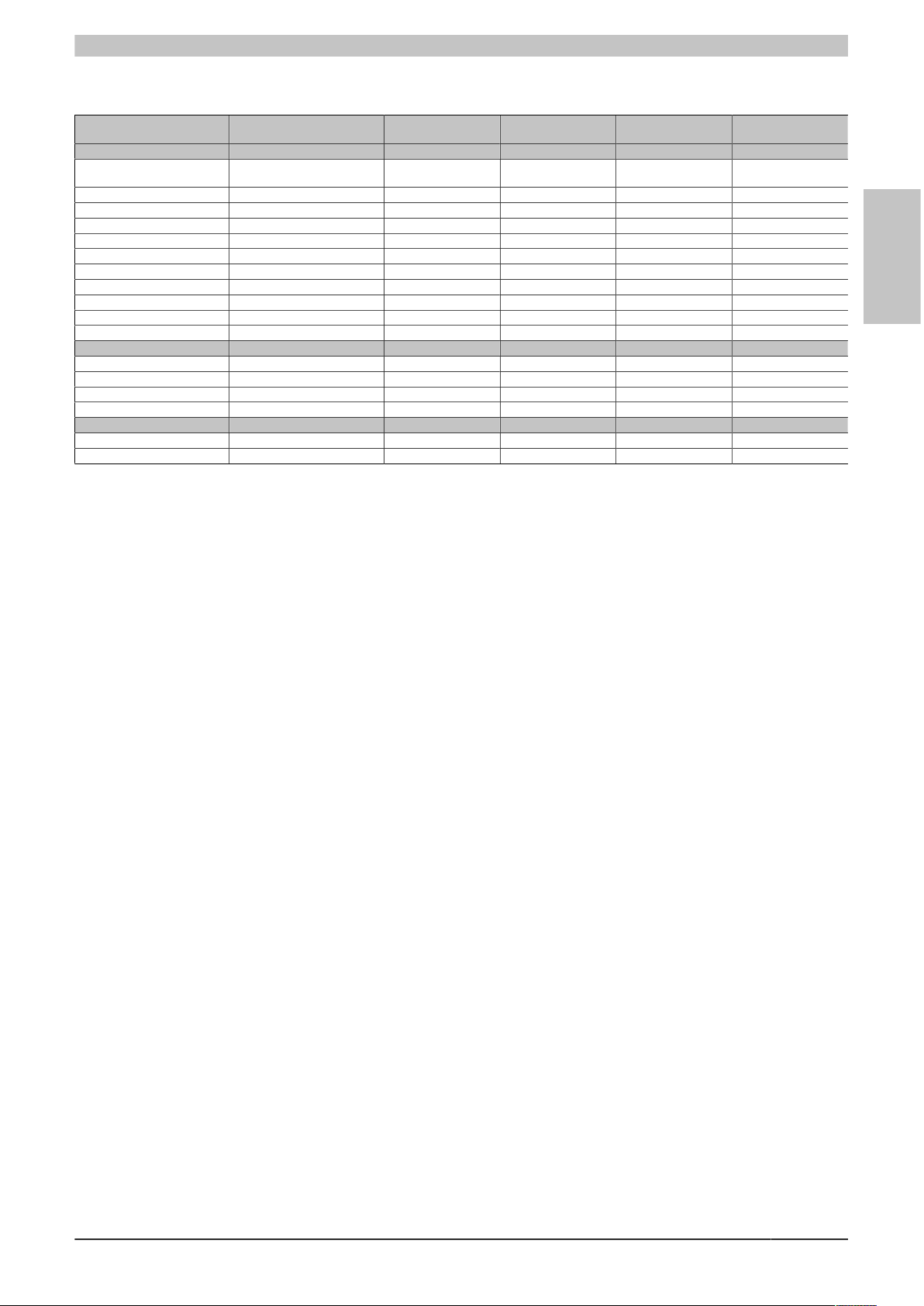
Technical data • Complete system
In order to accurately determine the total power of the complete system, the values in this table must be entered
in the power calculation table if one or more of these options are connected to the system unit.
Component Model number +5 V 3V3 12 V Power consumption
Interface option
RS232/RS422/RS485 IF op-
tion
CAN IF option 5AC901.ICAN-00 1 W - - 1 W
CAN IF option 5AC901.ICAN-01 0.5 W - - 0.5 W
Audio IF option 5AC901.IHDA-00 0.2 W 0.2 W - 0.4 W
POWERLINK IF option 5AC901.IPLK-00 - 1.5 W - 1.5 W
SRAM IF option 5AC901.ISRM-00 - 2 W - 2 W
Ready relay IF option 5AC901.IRDY-00 0.2 W - - 0.2 W
System I/O IF option 5AC901.ISIO-00 - 0.5 W - 0.5 W
UPS IF option 5AC901.IUPS-00 in standby - - 0.1 W 0.1 W
UPS IF option 5AC901.IUPS-01 in standby - - 0.1 W 0.1 W
Gigabit Ethernet IF option 5AC901.IETH-00 - 1 W - 1 W
Monitor/Panel option
DisplayPort transmitter 5AC901.LDPO-00 - 0.2 W - 0.2 W
SDL/DVI transmitter 5AC901.LSDL-00 - 1 W - 1 W
SDL3 transmitter 5AC901.LSD3-00 2.2 W 1.8 W - 4 W
SDL4 transmitter 5AC901.LSD4-00 2.5 W 2 W - 4.5 W
PCIe cards
PCIe x1 Ethernet card 5ACPCE.ETH1-00 - 1 W - 1 W
PCIe x4 Ethernet card 5ACPCE.ETH4-00 - 4 W - 4 W
5AC901.I485-00 1 W - - 1 W
Table 21: Interface and monitor/panel options - Power rating table
Total
Chapter 2
Technical data
Automation PC 910 user's manual V1.51 51
Page 52
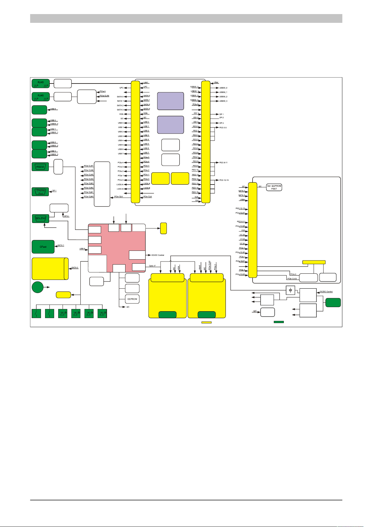
Technical data • Complete system
V battery
Reset
Button
Power
Button
Power LED
Green/Red
HDD LED
Yellow
Link LED
Yellow
Run LED
Green/Red
Temp
Sensor
Temp
Sensor
SPI flash
32 MB
Line
Driver
CMOS
<>
RS232
Battery
950 mAh
DP -> DVI
Converter
USB5
USB1
USB2
USB3
USB4
COM Express module
Type 6
Fans 1-4
Fans 1-4
FPGA MTCX
Controller
Intel PCH
Interface directed outwards
Interface - Optional or internal
Front panel
Connector
Temp.
Sensor
DC-to-DC
switching
DC-to-DC
isolated
DC-to-DC
isolated
Power
3-pin
Power sequencing
ACPI
MISC
PCIe
Clock
Buffer
Intel
Processor
Intel
Ethernet
Board
Controller
SO-DIMM
Module 1
SO-DIMM
Module 2
Intel
82574
V5A
V3.3A
V3.3S
V5S
V12S
SM bus
SM bus
SM bus
I2C
IF option
FPGA DC/DC
Control
FAN
Control
SMBLPC
UART1
SDL
USB
Analog RGB
Magnetics
Magnetics
Analog RGB
Analog RGB
SM bus
SM bus
COM Express C D
COM Express A B
LPC
LP connector PCIe X16
UBAT_
UPS
LP connector
PCIe X4
HDA
UPS
CAN
RS232/RS422/RS485
Ready relay
IF option 1
LP connector
PCIe X1
Hard disk drive
SSD
CFast
Slide-in compact
SRAM
CAN
RS232/RS422/RS485
Ready relay
IF option 2
PCIe -> PCI
Bridge
DC-to-DC
Switching
-12 PCI
32-bit PCI bus slot 1
5AC901.BX01-00 - 1-slot bus 1 PCI
SM bus
2.2.2 Block diagrams
The following block diagrams illustrate the simplified structure of system units with a CPU board in relation to the
various bus units.
2.2.2.1 5PC910.SX01-00 system unit + 5AC901.BX01-00 bus unit
Figure 6: 5PC910.SX01-00 system unit + 5AC901.BX01-00 bus unit - Block diagram
52 Automation PC 910 user's manual V1.51
Page 53
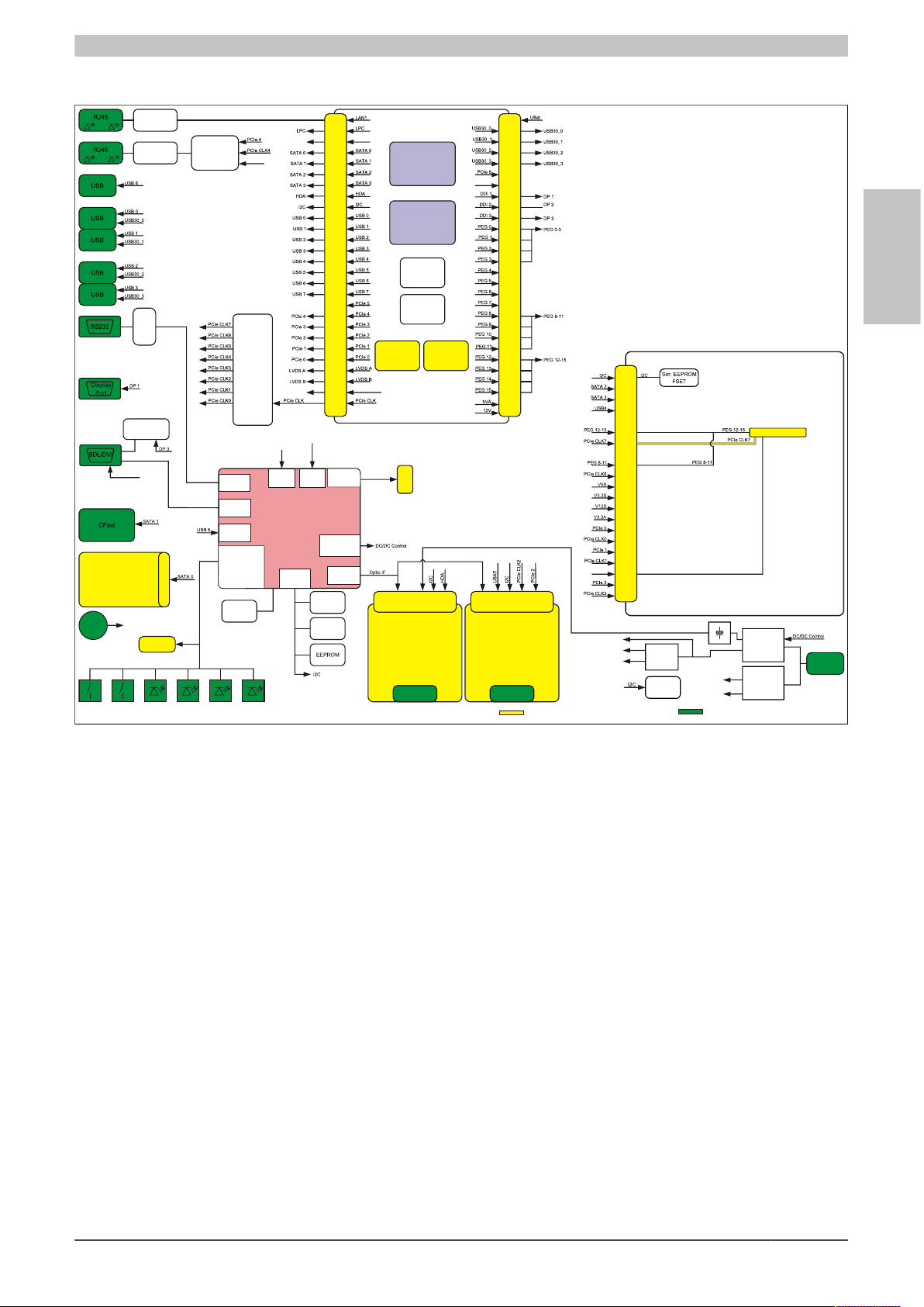
2.2.2.2 5PC910.SX01-00 system unit + 5AC901.BX01-01 bus unit
V battery
Reset
Button
Power
Button
Power LED
Green/Red
HDD LED
Yellow
Link LED
Yellow
Run LED
Green/Red
Temp
Sensor
Temp
Sensor
SPI flash
32 MB
Line
Driver
CMOS
<>
RS232
Battery
950 mAh
DP -> DVI
Converter
COM Express module
Type 6
Fans 1-4
Fans 1-4
FPGA MTCX
Controller
Intel PCH
Interface directed outwards
Interface - Optional or internal
Front panel
Connector
Temp.
Sensor
DC-to-DC
switching
DC-to-DC
isolated
DC-to-DC
isolated
Power
3-pin
Power sequencing
ACPI
MISC
PCIe
Clock
Buffer
Intel
Processor
Intel
Ethernet
Board
Controller
SO-DIMM
Module 1
SO-DIMM
Module 2
Intel
82574
V5A
V3.3A
V3.3S
V5S
V12S
SM bus
SM bus
SM bus
I2C
IF option
FPGA DC/DC
Control
FAN
Control
SMBLPC
UART1
SDL
USB
Analog RGB
Magnetics
Magnetics
Analog RGB
Analog RGB
SM bus
SM bus
COM Express C D
COM Express A B
LPC
LP connector PCIe X16
UBAT_
UPS
LP connector
PCIe X4
HDA
UPS
CAN
RS232/RS422/RS485
Ready relay
IF option 1
LP connector
PCIe X1
Hard disk drive
SSD
CFast
Slide-in compact
SRAM
CAN
RS232/RS422/RS485
Ready relay
IF option 2
PCIe X8 Slot 1
5AC901.BX01-01 - 1-slot bus 1 PCIe
SM bus
Technical data • Complete system
Chapter 2
Technical data
Figure 7: 5PC910.SX01-00 system unit + 5AC901.BX01-01 bus unit - Block diagram
Automation PC 910 user's manual V1.51 53
Page 54
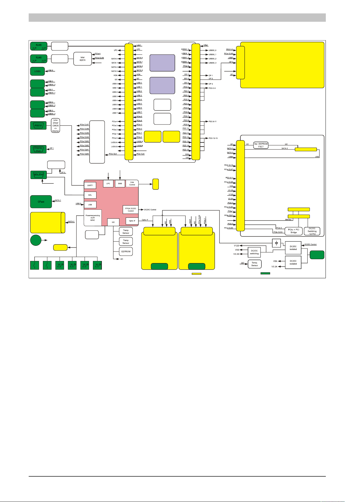
Technical data • Complete system
V battery
Reset
Button
Power
Button
Power LED
Green/Red
HDD LED
Yellow
Link LED
Yellow
Run LED
Green/Red
SPI flash
32 MB
Battery
950 mAh
DP -> DVI
Converter
COM Express module
Type 6
Fans 1-4
Fans 1-4
FPGA MTCX
Controller
Interface directed outwards
Interface - Optional or internal
Front panel
Connector
LP connector
PCIe X4
Power
3-pin
PCIe
Clock
Buffer
Intel
Processor
Intel
Ethernet
Board
Controller
SO-DIMM
Module 1
SO-DIMM
Module 2
SM bus
SM bus
SM bus
Analog RGB
Magnetics
Magnetics
Analog RGB
Analog RGB
SM bus
SM bus
COM Express C D
COM Express A B
LPC
LP connector PCIe X16
FPGA Link
USB1
USB2
USB3
USB4
Intel PCH
UBAT_
UPS
LP connector
PCIe X4
UPS
CAN
RS232/RS422/RS485
Ready relay
HDA
IF option 1
LP connector
PCIe X1
Hard disk drive
SSD
CFast
Slide-in compact
SRAM
CAN
Ready relay
RS232/RS422/RS485
IF option 2
Slide-in slot 1
32-bit PCI bus slot 2
32-bit PCI bus slot 1
5AC901.BX02-00 - 2-slot bus 2 PCI
DisplayPort transmitter
Smart Display Link / DVI transmitter
Monitor/Panel option
Smart Display Link 3 transmitter
2.2.2.3 5PC910.SX02-00 system unit + 5AC901.BX02-00 bus unit
Figure 8: 5PC910.SX02-00 system unit + 5AC901.BX02-00 bus unit - Block diagram
54 Automation PC 910 user's manual V1.51
Page 55
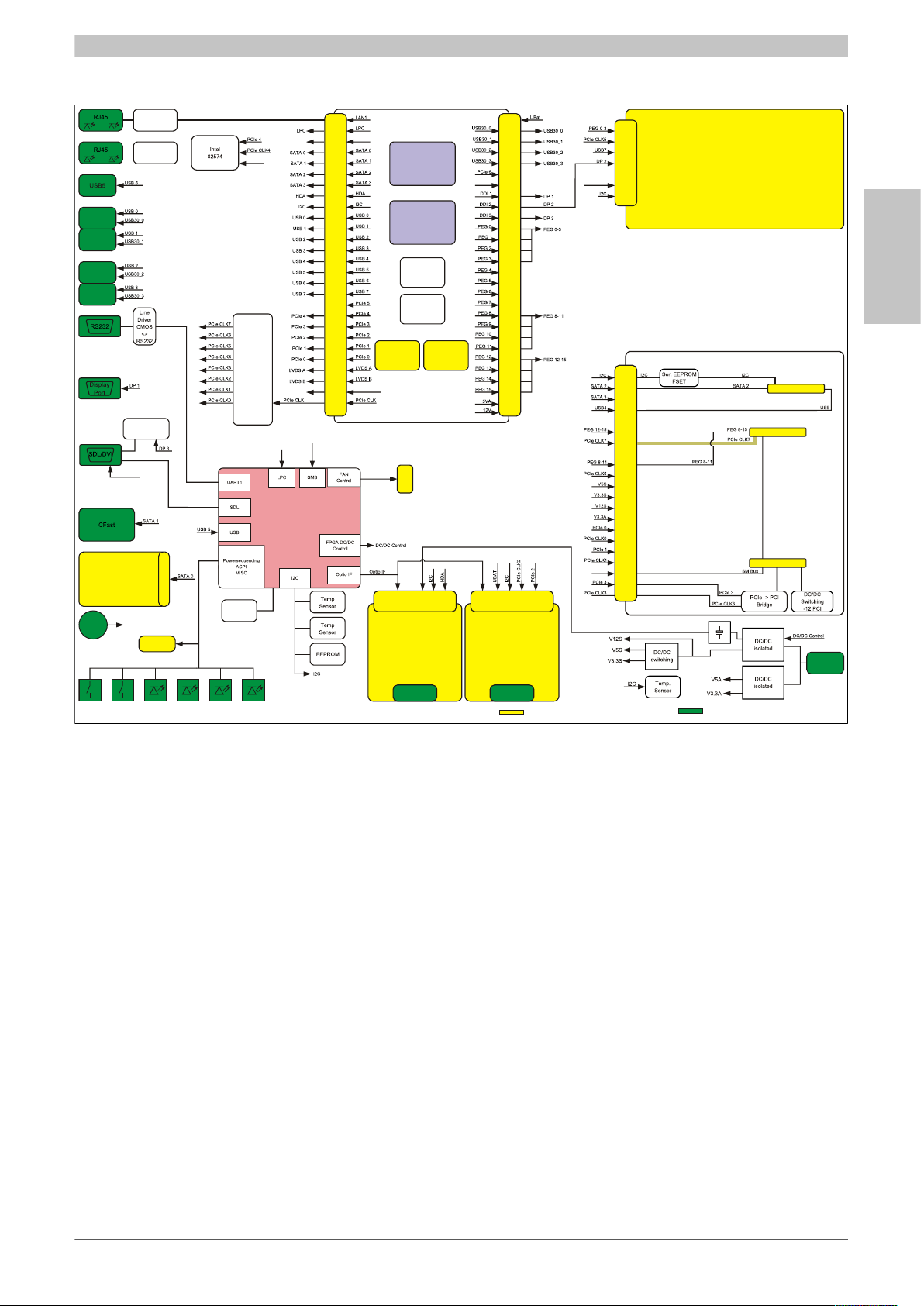
2.2.2.4 5PC910.SX02-00 system unit + 5AC901.BX02-01 bus unit
V battery
Reset
Button
Power
Button
Power LED
Green/Red
HDD LED
Yellow
Link LED
Yellow
Run LED
Green/Red
SPI flash
32 MB
Battery
950 mAh
DP -> DVI
Converter
COM Express module
Type 6
Fans 1-4
Fans 1-4
FPGA MTCX
Controller
Interface directed outwards
Interface - Optional or internal
Front panel
Connector
LP connector
PCIe X4
Power
3-pin
PCIe
Clock
Buffer
Intel
Processor
Intel
Ethernet
Board
Controller
SO-DIMM
Module 1
SO-DIMM
Module 2
SM bus
SM bus
SM bus
Analog RGB
Magnetics
Magnetics
Analog RGB
Analog RGB
SM bus
SM bus
COM Express C D
COM Express A B
LPC
LP connector PCIe X16
FPGA Link
USB1
USB2
USB3
USB4
Intel PCH
UBAT_
UPS
LP connector
PCIe X4
UPS
CAN
RS232/RS422/RS485
Ready relay
HDA
IF option 1
LP connector
PCIe X1
Hard disk drive
SSD
CFast
Slide-in compact
SRAM
CAN
Ready relay
RS232/RS422/RS485
IF option 2
32-bit PCI bus slot 2
PCIe X8 Slot 1
Slide-in slot 1
5AC901.BX02-01 - 2-slot bus 1 PCI / 1 PCIe
DisplayPort transmitter
Smart Display Link / DVI transmitter
Monitor/Panel option
Smart Display Link 3 transmitter
Technical data • Complete system
Chapter 2
Technical data
Figure 9: 5PC910.SX02-00 system unit + 5AC901.BX02-01 bus unit - Block diagram
Automation PC 910 user's manual V1.51 55
Page 56
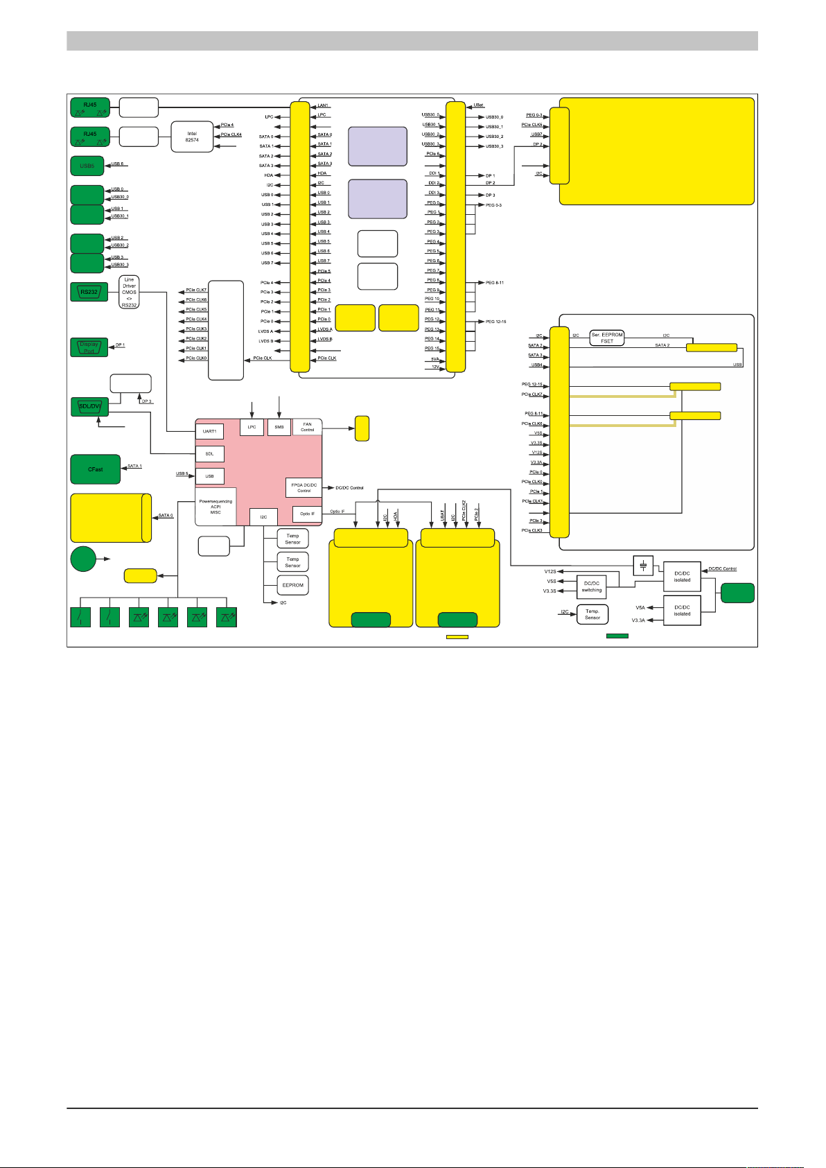
Technical data • Complete system
V battery
Reset
Butto
n
Power
Butto
n
Power LED
Green/Red
HDD LED
Yello
w
Link LED
Yello
w
Run LED
Green/Red
SPI fla
sh
32 MB
Battery
950 mAh
DP -> DVI
Converte
r
COM Express modul
e
Type
6
F
a
n
s
1
-
4
Fans 1-4
FPGA MTCX
Controlle
r
Interface directed outwards
Interface - Optional or interna
l
Front panel
Connecto
r
L
P
co
n
n
e
ct
o
r
P
C
I
e
X
4
Power
3-pin
PCI
e
Clock
Buffe
r
Intel
Processor
Intel
Etherne
t
Board
Controlle
r
SO-DIMM
Module
1
SO-DIMM
Module
2
SM bu
s
SM bu
s
S
M
b
u
s
Analog RG
B
Magneti
cs
Magneti
cs
Analog RG
B
Analog RG
B
SM bu
s
SM bu
s
C
O
M
E
xp
r
e
ss
C
D
C
O
M
E
xp
r
e
ss
A
B
L
P
C
L
P
co
n
n
e
ct
o
r
P
C
I
e
X
1
6
FPGA Link
USB
1
USB
2
USB
3
USB
4
Intel PCH
U
B
A
T
_
U
P
S
LP connecto
r
PCIe X4
UPS
CAN
RS232/RS422/RS485
Ready rela
y
HDA
IF option 1
LP connecto
r
PCIe X1
Hard di
sk drive
SSD
CFa
st
Slide-in compac
t
SRA
M
CAN
Ready rela
y
RS232/RS422/RS485
IF option 2
PEG 12-15
PCIe CLK7
SM bu
s
PCIe X4 Slot
1
PEG 8-11
PCIe CLK6
PCIe X4 Slot
2
Slide-in slot 1
5AC901.BX02-02 - 2-slot bus 2 PCI
e
DisplayPort transmitte
r
Smart Display Link / DVI transmitte
r
Monitor/Panel optio
n
Smart Display Link 3 transmitte
r
2.2.2.5 5PC910.SX02-00 system unit + 5AC901.BX02-02 bus unit
Figure 10: 5PC910.SX02-00 system unit + 5AC901.BX02-02 bus unit - Block diagram
56 Automation PC 910 user's manual V1.51
Page 57
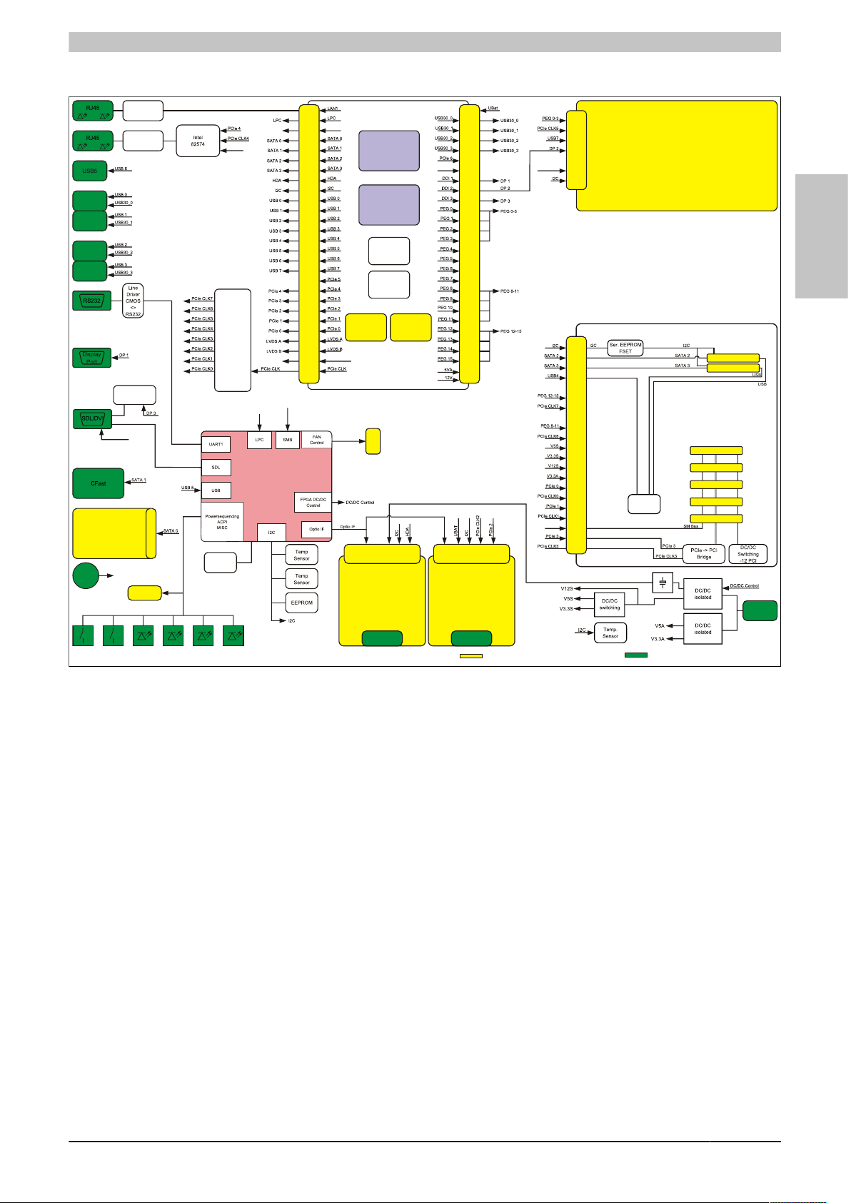
2.2.2.6 5PC910.SX05-00 system unit + 5AC901.BX05-00 bus unit
V battery
Reset
Button
Power
Button
Power LED
Green/Red
HDD LED
Yellow
Link LED
Yellow
Run LED
Green/Red
SPI flash
32 MB
Battery
950 mAh
DP -> DVI
Converter
COM Express module
Type 6
Fans 1-4
Fans 1-4
FPGA MTCX
Controller
Interface directed outwards
Interface - Optional or internal
Front panel
Connector
LP connector
PCIe X4
Power
3-pin
PCIe
Clock
Buffer
Intel
Processor
Intel
Ethernet
Board
Controller
SO-DIMM
Module 1
SO-DIMM
Module 2
SM bus
SM bus
SM bus
Analog RGB
Magnetics
Magnetics
Analog RGB
Analog RGB
SM bus
SM bus
COM Express C D
COM Express A B
LPC
LP connector PCIe X16
FPGA Link
USB1
USB2
USB3
USB4
Intel PCH
UBAT_
UPS
LP connector
PCIe X4
UPS
CAN
RS232/RS422/RS485
Ready relay
HDA
IF option 1
LP connector
PCIe X1
Hard disk drive
SSD
CFast
Slide-in compact
SRAM
CAN
Ready relay
RS232/RS422/RS485
IF option 2
32-bit PCI bus slot 5
32-bit PCI bus slot 4
32-bit PCI bus slot 3
Slide-in slot 1
Slide-in slot 2
USB hub
5AC901.BX05-00 - 5-slot bus 5 PCI
32-bit PCI bus slot 2
32-bit PCI bus slot 1
DisplayPort transmitter
Smart Display Link / DVI transmitter
Monitor/Panel option
Smart Display Link 3 transmitter
Technical data • Complete system
Chapter 2
Technical data
Figure 11: 5PC910.SX05-00 system unit + 5AC901.BX05-00 bus unit - Block diagram
Automation PC 910 user's manual V1.51 57
Page 58
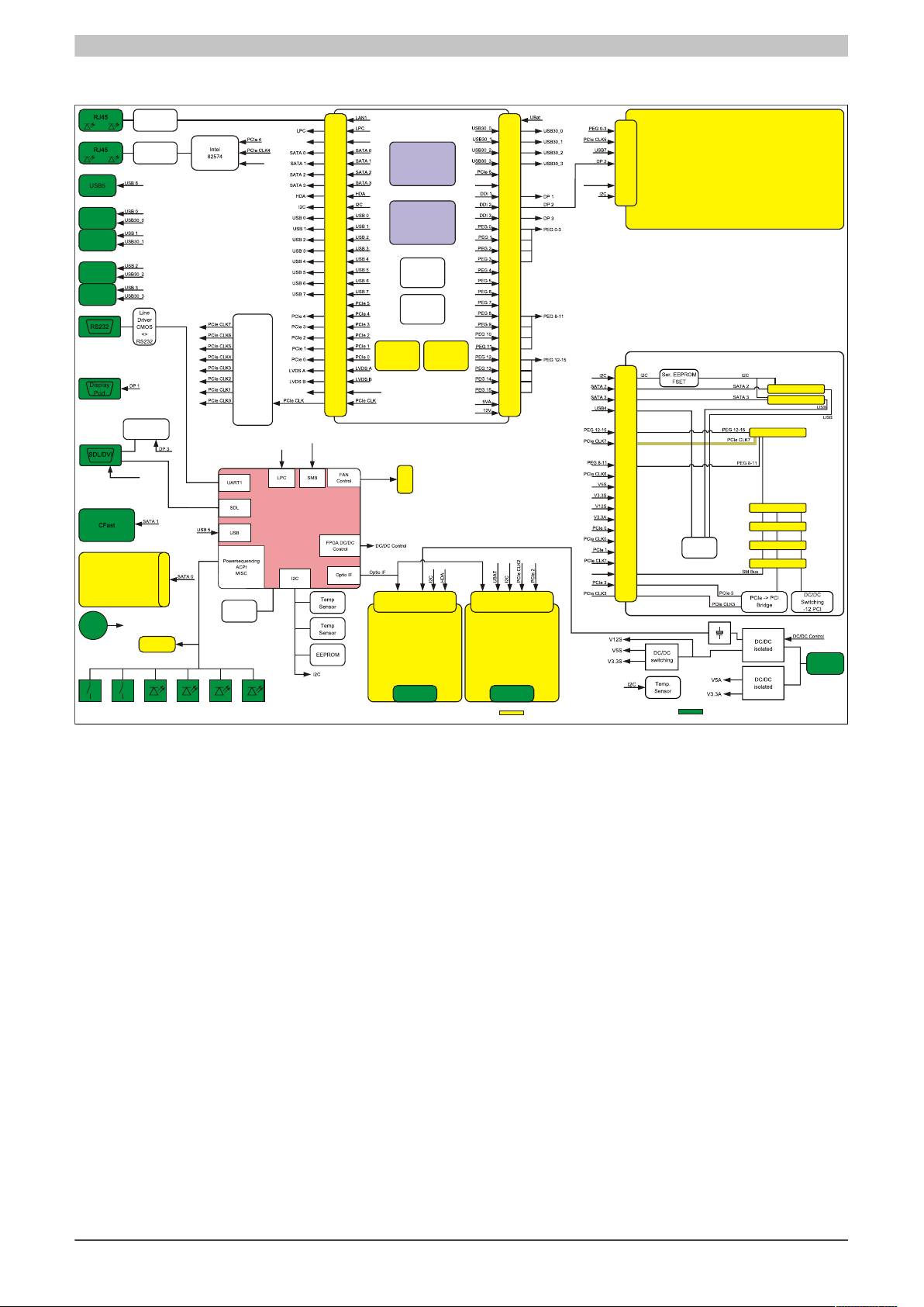
Technical data • Complete system
V battery
Reset
Button
Power
Button
Power LED
Green/Red
HDD LED
Yellow
Link LED
Yellow
Run LED
Green/Red
SPI flash
32 MB
Battery
950 mAh
DP -> DVI
Converter
COM Express module
Type 6
Fans 1-4
Fans 1-4
FPGA MTCX
Controller
Interface directed outwards
Interface - Optional or internal
Front panel
Connector
LP connector
PCIe X4
Power
3-pin
PCIe
Clock
Buffer
Intel
Processor
Intel
Ethernet
Board
Controller
SO-DIMM
Module 1
SO-DIMM
Module 2
SM bus
SM bus
SM bus
Analog RGB
Magnetics
Magnetics
Analog RGB
Analog RGB
SM bus
SM bus
COM Express C D
COM Express A B
LPC
LP connector PCIe X16
FPGA Link
USB1
USB2
USB3
USB4
Intel PCH
UBAT_
UPS
LP connector
PCIe X4
UPS
CAN
RS232/RS422/RS485
Ready relay
HDA
IF option 1
LP connector
PCIe X1
Hard disk drive
SSD
CFast
Slide-in compact
SRAM
CAN
Ready relay
RS232/RS422/RS485
IF option 2
32-bit PCI bus slot 5
32-bit PCI bus slot 4
PCIe X8 Slot 1
32-bit PCI bus slot 3
Slide-in slot 1
Slide-in slot 2
5AC901.BX05-01 - 5-slot bus 4 PCI / 1 PCIe
32-bit PCI bus slot 2
USB hub
DisplayPort transmitter
Smart Display Link / DVI transmitter
Monitor/Panel option
Smart Display Link 3 transmitter
2.2.2.7 5PC910.SX05-00 system unit + 5AC901.BX05-01 bus unit
Figure 12: 5PC910.SX05-00 system unit + 5AC901.BX05-01 bus unit - Block diagram
58 Automation PC 910 user's manual V1.51
Page 59
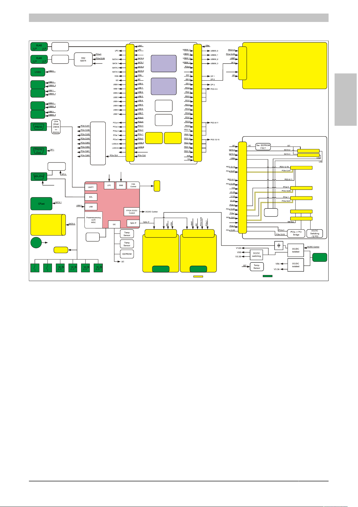
2.2.2.8 5PC910.SX05-00 system unit + 5AC901.BX05-02 bus unit
V battery
Reset
Button
Power
Button
Power LED
Green/Red
HDD LED
Yellow
Link LED
Yellow
Run LED
Green/Red
SPI flash
32 MB
Battery
950 mAh
DP -> DVI
Converter
COM Express module
Type 6
Fans 1-4
Fans 1-4
FPGA MTCX
Controller
Interface directed outwards
Interface - Optional or internal
Front panel
Connector
LP connector
PCIe X4
Power
3-pin
PCIe
Clock
Buffer
Intel
Processor
Intel
Ethernet
Board
Controller
SO-DIMM
Module 1
SO-DIMM
Module 2
SM bus
SM bus
SM bus
Analog RGB
Magnetics
Magnetics
Analog RGB
Analog RGB
SM bus
SM bus
COM Express C D
COM Express A B
LPC
LP connector PCIe X16
FPGA Link
USB1
USB2
USB3
USB4
Intel PCH
UBAT_
UPS
LP connector
PCIe X4
UPS
CAN
RS232/RS422/RS485
Ready relay
HDA
IF option 1
LP connector
PCIe X1
Hard disk drive
SSD
CFast
Slide-in compact
SRAM
CAN
Ready relay
RS232/RS422/RS485
IF option 2
PCIe X1 Slot 2
PCIe X1 Slot 1
32-bit PCI bus slot 5
32-bit PCI bus slot 4
PCIe X8 Slot 3
Slide-in slot 1
Slide-in slot 2
USB hub
5AC901.BX05-02 - 5-slot bus 2 PCI / 3 PCIe
DisplayPort transmitter
Smart Display Link / DVI transmitter
Monitor/Panel option
Smart Display Link 3 transmitter
Technical data • Complete system
Chapter 2
Technical data
Figure 13: 5PC910.SX05-00 system unit + 5AC901.BX05-02 bus unit - Block diagram
Automation PC 910 user's manual V1.51 59
Page 60
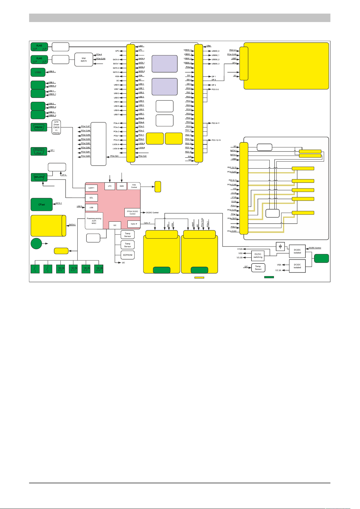
Technical data • Complete system
V battery
Reset
Butto
n
Power
Butto
n
Power LED
Green/Red
HDD LED
Yello
w
Link LED
Yello
w
Run LED
Green/Red
SPI fla
sh
32 MB
Battery
950 mAh
DP -> DVI
Converte
r
COM Express modul
e
Type
6
F
a
n
s
1
-
4
Fans 1-4
FPGA MTCX
Controlle
r
Interface directed outwards
Interface - Optional or interna
l
Front panel
Connecto
r
L
P
co
n
n
e
ct
o
r
P
C
I
e
X
4
Power
3-pin
PCI
e
Clock
Buffe
r
Intel
Processor
Intel
Etherne
t
Board
Controlle
r
SO-DIMM
Module
1
SO-DIMM
Module
2
SM bu
s
SM bu
s
S
M
b
u
s
Analog RG
B
Magneti
cs
Magneti
cs
Analog RG
B
Analog RG
B
SM bu
s
SM bu
s
C
O
M
E
xp
r
e
ss
C
D
C
O
M
E
xp
r
e
ss
A
B
L
P
C
L
P
co
n
n
e
ct
o
r
P
C
I
e
X
1
6
FPGA Link
USB
1
USB
2
USB
3
USB
4
Intel PCH
U
B
A
T
_
U
P
S
LP connecto
r
PCIe X4
UPS
CAN
RS232/RS422/RS485
Ready rela
y
HDA
IF option 1
LP connecto
r
PCIe X1
Hard di
sk drive
SSD
CFa
st
Slide-in compac
t
SRA
M
CAN
Ready rela
y
RS232/RS422/RS485
IF option 2
PCIe
3
PCIe CLK3
PCIe
0
PCIe CLK0
PEG 12-15
PCIe CLK7
PCIe X1 Slot
1
PCIe X4 Slot
3
Slide-in slot 1
I2C
Ser. EEPROM
FSE
T
Slide-in slot 2
USB hub
PCIe X1 Slot
5
I2C
SATA
2
USB
USB
SATA
3
5AC901.BX05-03 - 5-slot bus 5 PCI
e
SM bu
s
PEG 8-11
PCIe CLK6
PCIe X4 Slot
4
PCIe
1
PCIe CLK1
PCIe X1 Slot
2
DisplayPort transmitte
r
Smart Display Link / DVI transmitte
r
Monitor/Panel optio
n
Smart Display Link 3 transmitte
r
2.2.2.9 5PC910.SX05-00 system unit + 5AC901.BX05-03 bus unit
Figure 14: 5PC910.SX05-00 system unit + 5AC901.BX05-03 bus unit - Block diagram
60 Automation PC 910 user's manual V1.51
Page 61
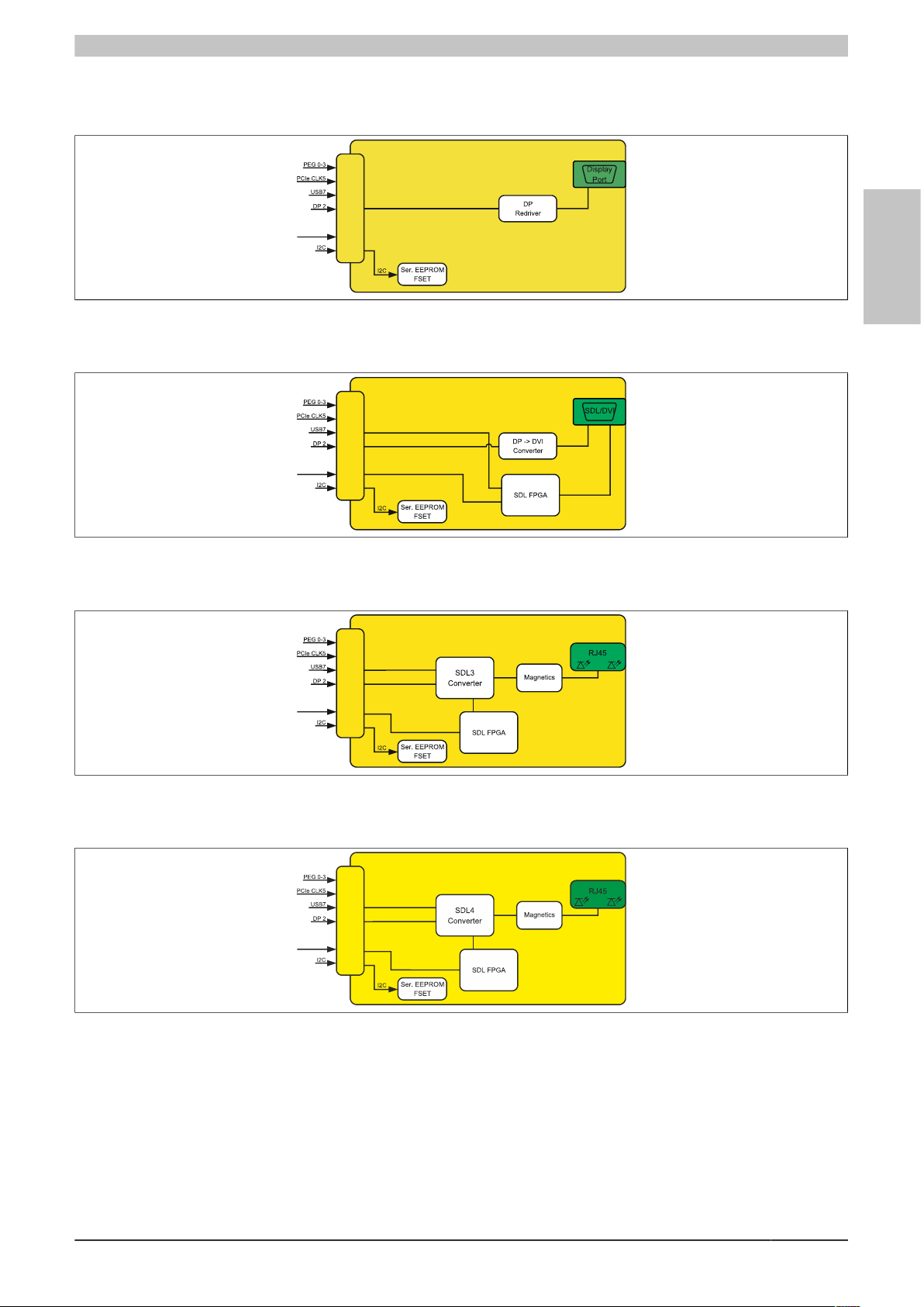
2.2.2.10 Monitor/Panel options
LP connector
PCIe X4
FPGA Link
DisplayPort transmitter
LP connector
PCIe X4
FPGA Link
Smart Display Link / DVI transmitter
LP connector
PCIe X4
FPGA Link
SDL3 transmitter
L
P
c
o
n
n
e
c
t
o
r
P
C
I
e
X
4
FPGA Link
SDL4 transmitte
r
DisplayPort transmitter
Figure 15: 5AC901.LDPO-00 DisplayPort transmitter - Block diagram
SDL/DVI transmitter
Technical data • Complete system
Chapter 2
Technical data
SDL3 transmitter
SDL4 transmitter
Figure 16: 5AC901.LSDL-00 Smart Display Link / DVI transmitter - Block diagram
Figure 17: 5AC901.LSD3-00 Smart Display Link 3 transmitter - Block diagram
Figure 18: 5AC901.LSD4-00 Smart Display Link 4 transmitter - Block diagram
Automation PC 910 user's manual V1.51 61
Page 62
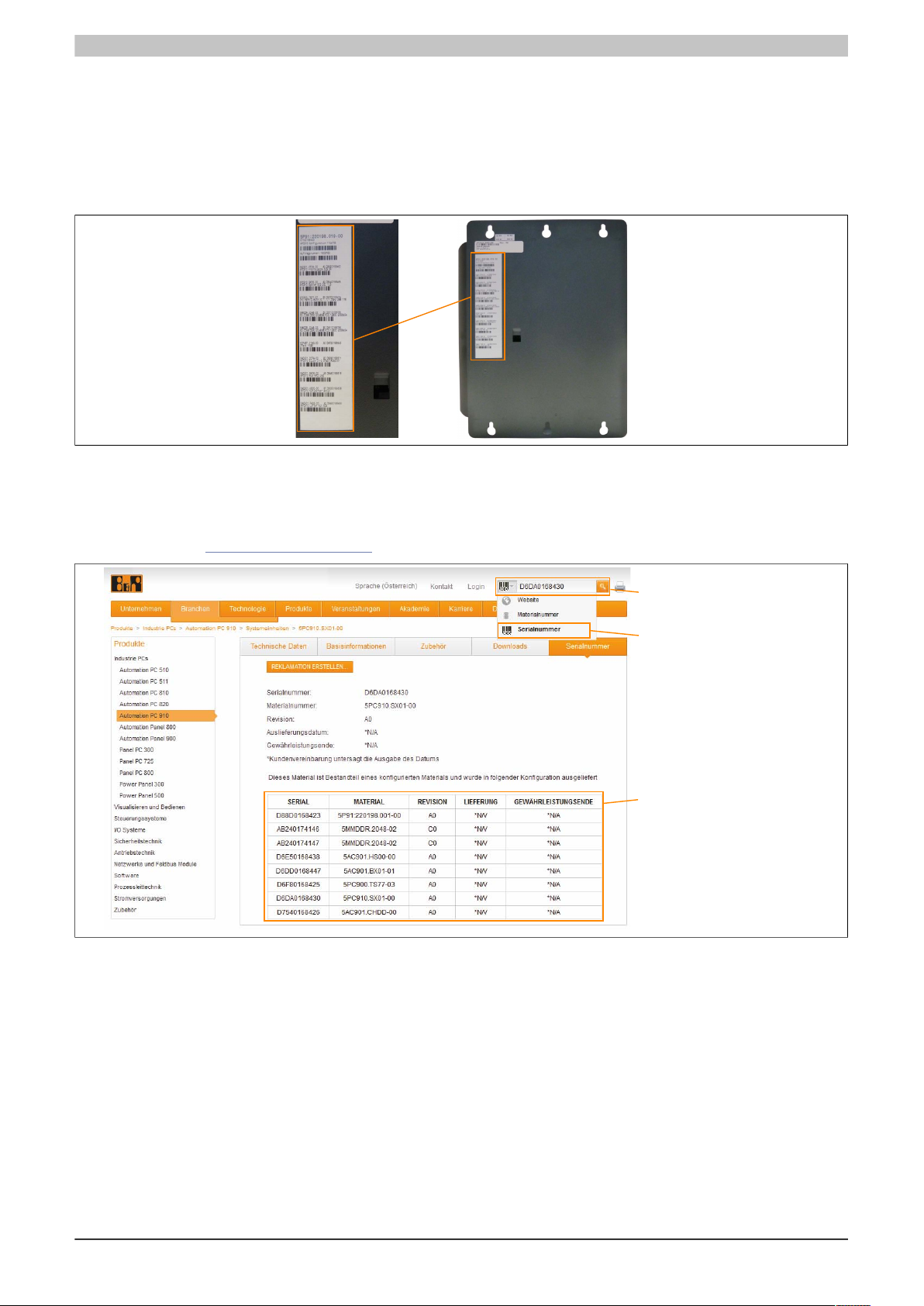
Technical data • Complete system
List of installed
components shown after
searching for a serial number
Switch to the option
"Serial number"
Enter serial number
e.g. D6DA0168430
2.3 Serial number sticker
A unique serial number sticker with a barcode (Code 128) is affixed to each B&R device for identification purposes.
This serial number represents all of the individual components built into the system (model number, name, revision,
serial number, delivery date and duration of warranty).
A sticker with detailed information about the installed components can also be found on the back of the mounting
plate.
Figure 19: Serial number sticker (back)
The serial number represents all of the individual components built into the system (serial number, model number,
revision, delivery date and duration of warranty). This information can also be found on the B&R website by entering
the serial number of the complete system in the search field tab (after selecting the "Serial number" option) at the
top of the website (www.br-automation.com). The search provides a detailed list of installed components.
Figure 20: Searching for a serial number on the B&R website
62 Automation PC 910 user's manual V1.51
Page 63
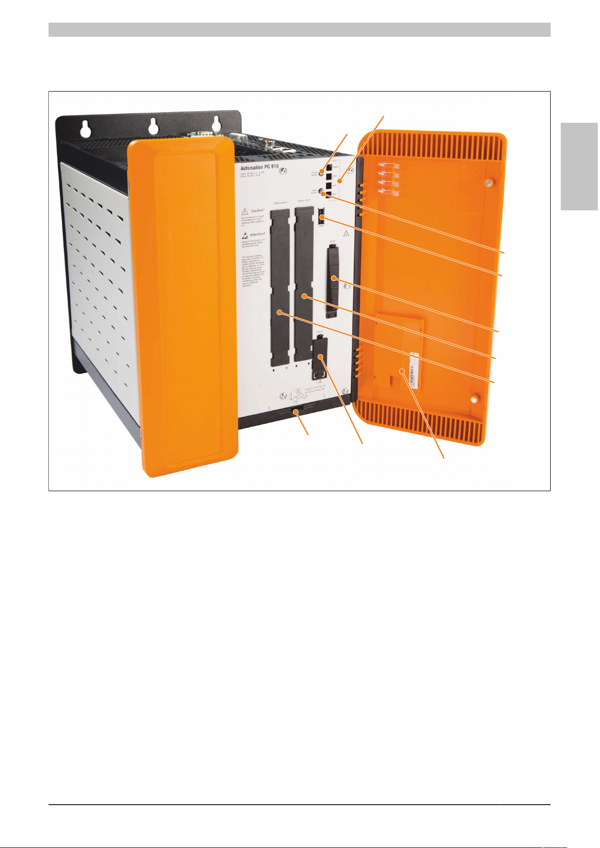
2.4 Device interfaces and slots
LED status indicators:
Power, HDD, Link, Run
Reset button
Power button
USB5
CFast slot
Fan kit insert
Storage tray
for CFast card
Battery
Slide-in slot 1
Slide-in slot 2
2.4.1 Device interfaces - Overview
Technical data • Complete system
Chapter 2
Technical data
Figure 21: Device interfaces - Overview (front)
Automation PC 910 user's manual V1.51 63
Page 64
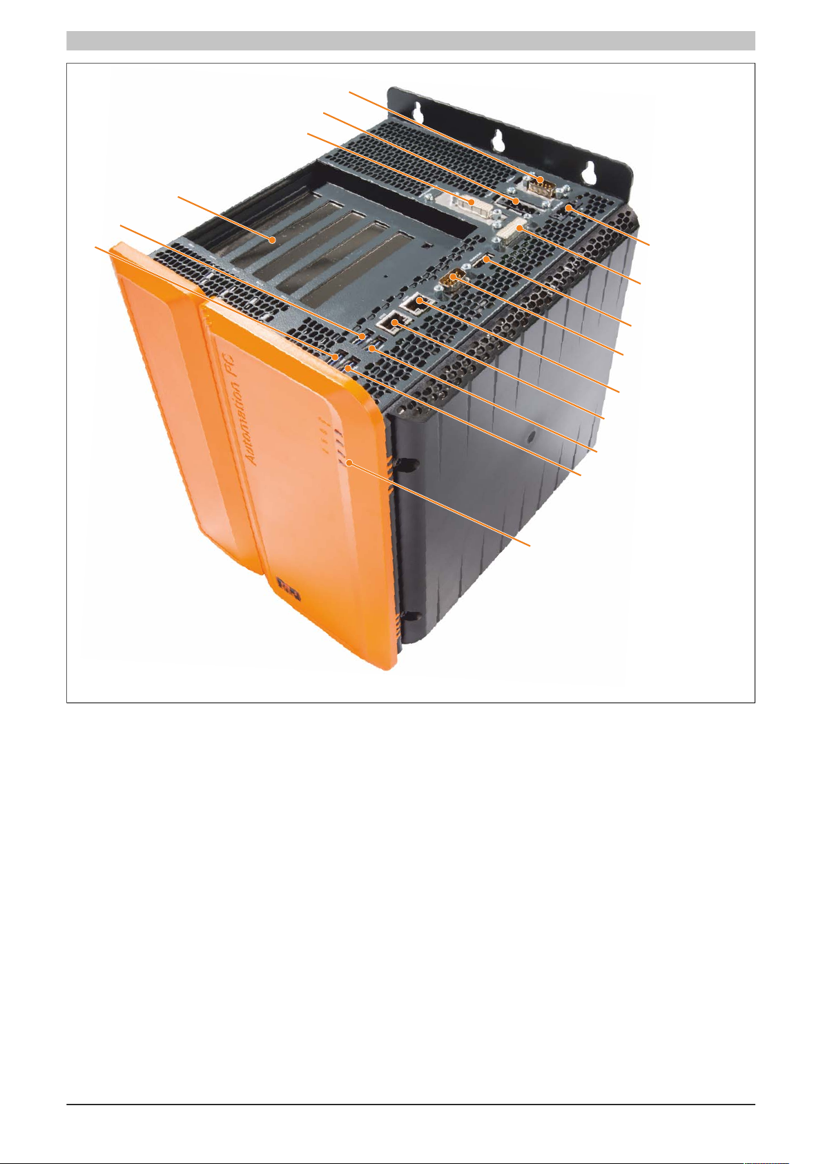
Technical data • Complete system
LED status indicators:
Power, HDD, Link, Run
USB3
USB4
Ethernet 2 (ETH2)
Ethernet 1 (ETH1)
RS232 (COM1)
DisplayPort
Power supply
+24 VDC
Interface option 2
Interface option 1
Monitor/Panel interface
SDL/DVI/RGB
Card slot 5
PCI or PCIe*
USB2
USB1
* Depends on the bus unit used
Monitor/Panel interface
SDL/DVI/RGB
Figure 22: Device interfaces - Overview (top)
64 Automation PC 910 user's manual V1.51
Page 65
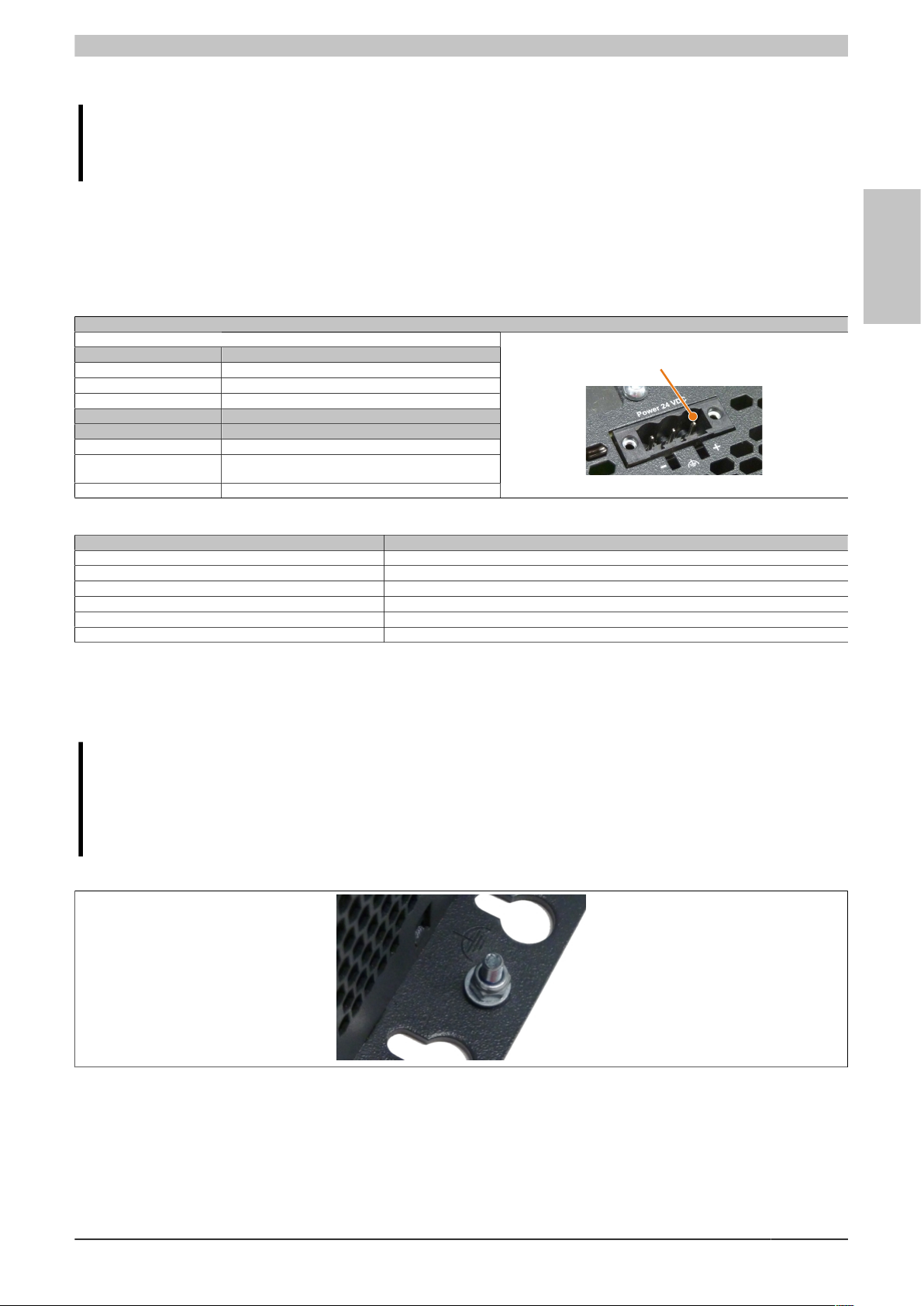
Technical data • Complete system
Power supply
+24 VDC
2.4.2 Power supply +24 VDC
Danger!
This device is only permitted to by supplied by a SELV/PELV power supply or with safety extra-low
voltage (SELV) per EN 60950.
The 3-pin male connector required for the power supply interface is not included in delivery. It can be ordered from
B&R using model number 0TB103.9 (screw clamps) or 0TB103.91 (cage clamp terminal block).
The pinout is listed in the following table and printed on the housing. The supply voltage is protected internally by
a soldered fuse (15 A, fast-acting) to prevent damage to the device in the event of an overload (fuse replacement
necessary) or if the voltage supply is connected incorrectly (reverse polarity protection -> fuse replacement not
necessary). The device must be returned to B&R for repairs if the fuse is blown in the event of an error.
Pin Description
Protected against reverse polarity
1 +
2 Functional ground
3 -
Model number Short description
Terminal blocks
0TB103.9 Male connector 24 V 5.08 3-pin screw clamps
0TB103.91 Male connector 24 V 5.08 3-pin cage clamp terminal
block
Power supply
3-pin male power supply connector
Chapter 2
Technical data
Table 22: 24 VDC voltage supply connection
Electrical characteristics
Nominal voltage 24 VDC ±25%, SELV
Nominal current Max. 5.5 A
Overvoltage category in accordance with EN 61131-2 II
Inrush current Max. 60 A for <300 μs
Electrical isolation Yes
Uninterruptible power supply No
1) EN 60950 requirements must be observed.
2) Maximum current consumption (24 V / 130 W). This can vary depending on the configuration (see "Power calculation" section). The inrush current must also
be taken into consideration when selecting the power supply.
2)
1)
2.4.2.1 Grounding
Caution!
Functional ground (pin 2 of power supply and ground connection) must be connected to the central
grounding point (e.g. of the control cabinet or system) using the shorted path with the lowest resistance
and largest possible wire cross section. This type of grounding is mandatory to ensure the system
functions properly.
The ground connection is located on the bottom of the APC910 system.
The M4 self-locking nut must be used, for example, to fasten a copper strip to a central grounding point in the
control cabinet or system where the APC910 is installed. The largest possible conductor cross section should be
used (at least 2.5 mm²).
Automation PC 910 user's manual V1.51 65
Figure 23: Ground connection
Page 66

Technical data • Complete system
5
1
9
6
2.4.3 COM1 serial interface
RS232
COM1 serial interface
Type RS232, modem-capable, not electrically isolated
UART 16550-compatible, 16-byte FIFO
Transfer rate Max. 115 kbit/s
Bus length Max. 15 m
Pin Assignment
1 DCD
2 RXD
3 TXD
4 DTR
5 GND
6 DSR
7 RTS
8 CTS
9 RI
1)
9-pin, male, DSUB connector
Table 23: COM1 - Pinout
1) The interfaces, etc. available on the device or module have been numbered as such for easy identification. This numbering may differ from that used by
the particular operating system.
66 Automation PC 910 user's manual V1.51
Page 67
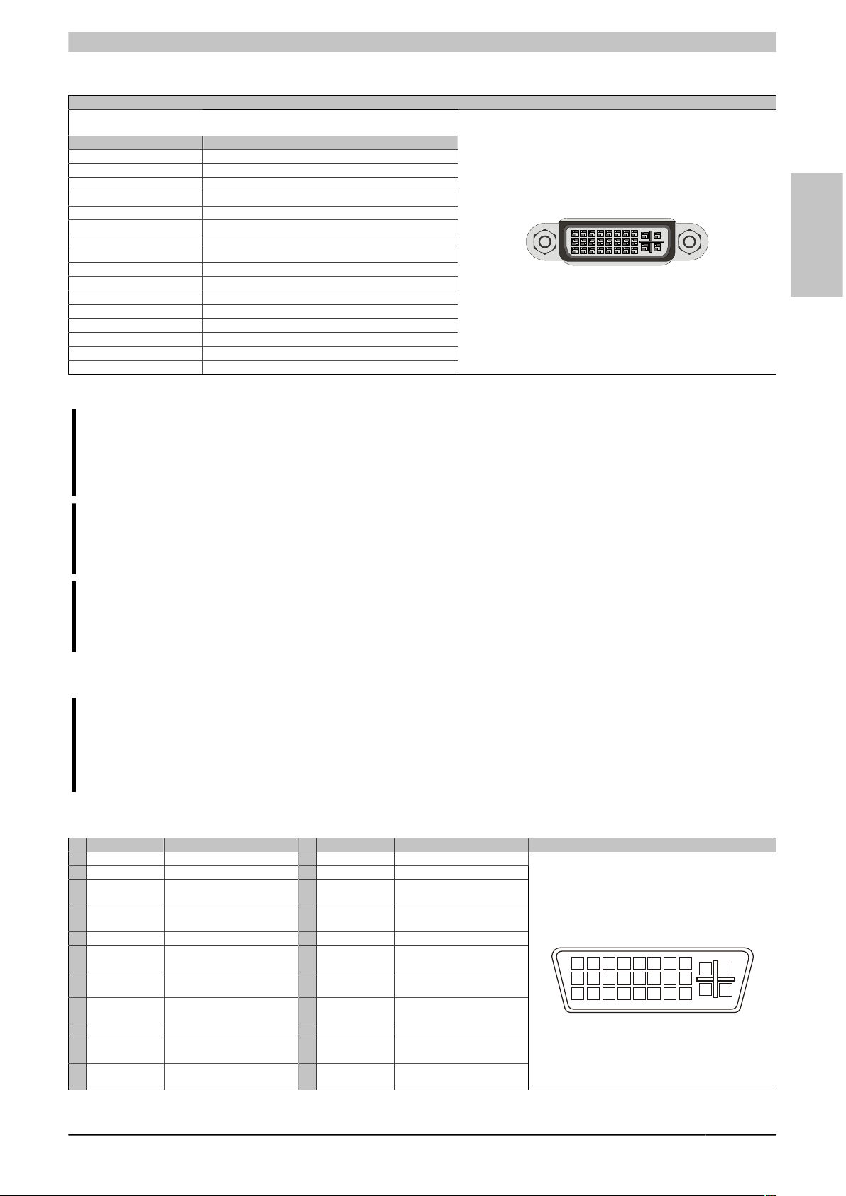
2.4.4 Panel/Monitor interface
678
5
1
2
3
4
14
15 16
13
9
10
11
12
222324
21
17
181920
c1
c4
c2
c3
c5
Technical data • Complete system
The following overview lists the video signals available on the monitor/panel output. For
Panel/Monitor interface - SDL (Smart Display Link) / DVI / RGB
details, see the technical data for the CPU board being used.
CPU board Video signals with all system unit variants
5PC900.TS17-00 SDL, DVI, RGB
5PC900.TS17-01 SDL, DVI, RGB
5PC900.TS17-02 SDL, DVI, RGB
5PC900.TS17-03 SDL, DVI, RGB
5PC900.TS17-04 SDL, DVI, RGB
5PC900.TS77-00 SDL, DVI, RGB
5PC900.TS77-01 SDL, DVI, RGB
5PC900.TS77-02 SDL, DVI, RGB
5PC900.TS77-03 SDL, DVI, RGB
5PC900.TS77-04 SDL, DVI, RGB
5PC900.TS77-05 SDL, DVI, RGB
5PC900.TS77-06 SDL, DVI, RGB
5PC900.TS77-07 SDL, DVI, RGB
5PC900.TS77-08 SDL, DVI, RGB
5PC900.TS77-09 SDL, DVI, RGB
5PC900.TS77-10 SDL, DVI, RGB
Table 24: Panel/Monitor interface - SDL, DVI, RGB
Information:
The hardware and graphics drivers of approved operating systems support the hot plugging of display
devices to the panel/monitor interface for service purposes. The panel/monitor connector is specified
for 100 connection cycles.
Chapter 2
Technical data
Information:
If a display device with touch screen is connected to the panel/monitor interface and then disconnected
again during operation (hot plugging), it may be necessary to recalibrate the touch screen.
Information:
The RGB interface uses an analog signal; the line length depends on the resolution and prevailing
environmental conditions. This interface is therefore only recommended for service purposes.
2.4.4.1 USB transfer in SDL and DVI mode
Information:
The USB transfer rate is limited to USB 1.1 in SDL mode.
In DVI mode, the maximum USB transfer rate depends on the USB interface and USB hub on the display
device.
2.4.4.2 Pinout
Pin Assignment Description Pin Assignment Description
1 TMDS data 2- DVI lane 2 (negative) 16 HPD Hot plug detect
2 TMDS data 2+ DVI lane 2 (positive) 17 TMDS data 0- DVI lane 0 (negative)
3 TMDS data 2/4
SHIELD
4
SDL- SDL lane (negative) 19
5 SDL+ SDL lane (positive) 20 XUSB1- USB lane 1 (negative)
6
DDC clock
7
DDC data
8 ANALOG VERT
SYNC
9 TMDS data 1- DVI lane 1 (negative) 24 TMDS clock - DVI clock (negative)
10
TMDS DATA 1+
TMDS DATA 1/
11
XUSB0 SHIELD
Shield for data pair 2 and 4 18 TMDS data 0+ DVI lane 0 (positive)
DDC-based control signal
(clock)
DDC-based control signal
(data)
Analog vertical synchronization
DVI lane 1 (negative) HDMI
clock (positive)
Shield for data pair 1 and
USB0
TMDS data 0/
XUSB1 SHIELD
21 XUSB1+ USB lane 1 (positive)
TMDS clock
22
shield
23 TMDS clock+ DVI clock (positive)
C1 ANALOG RED Analog Red
ANALOG
C2
GREEN
Shield for data pair 0 and
USB1
Shield for clock pair
Analog Green
Table 25: DVI interface - Pinout
DVI, 24-pin, female
Automation PC 910 user's manual V1.51 67
Page 68
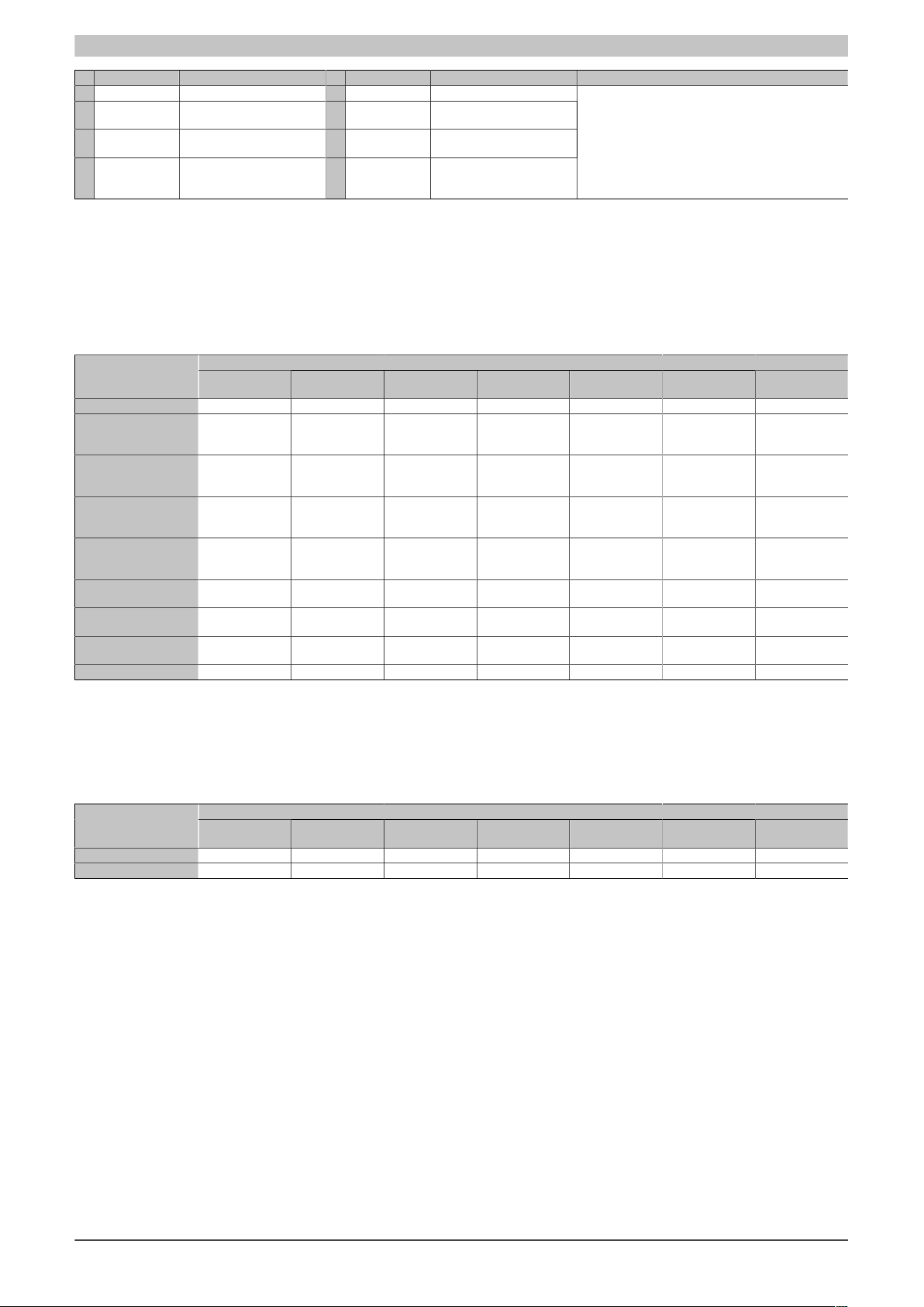
Technical data • Complete system
Pin Assignment Description Pin Assignment Description
12 XUSB0- USB lane 0 (negative) C3 ANALOG BLUE Analog Blue
13
XUSB0+ USB lane 0 (positive) C4
14 +5 V power1)+5 V power supply C5 Analog GND
Ground (return
15
for +5 V, HSync
and VSync)
Ground
ANALOG
HORZ SYNC
Analog horizontal synchronization
Analog ground (return for R,
G and B signals)
Table 25: DVI interface - Pinout
1) Protected internally by a multifuse.
2.4.4.3 Cable lengths and resolutions for SDL transmission
The following table lists the relationship between segment lengths and maximum resolution depending on the SDL
cable being used:
Segment length [m]
0.8 5CASDL.0008-00 5CASDL.0008-00 5CASDL.0008-00 5CASDL.0008-00 5CASDL.0008-00 5CASDL.0008-00 5CASDL.0008-00
1.8
5
10
15
20
25
30
40 5CASDL.0400-13 5CASDL.0400-13 5CASDL.0400-13 5CASDL.0400-13 5CASDL.0400-13 - 5CASDL.0400-13
VGA
640 x 480
5CASDL.0018-00
5CASDL.0018-01
5CASDL.0018-03
5CASDL.0050-00
5CASDL.0050-01
5CASDL.0050-03
5CASDL.0100-00
5CASDL.0100-01
5CASDL.0100-03
5CASDL.0150-00
5CASDL.0150-01
5CASDL.0150-03
5CASDL.0200-00
5CASDL.0200-03
5CASDL.0250-00
5CASDL.0250-03
5CASDL.0300-00
5CASDL.0300-03
SVGA
800 x 600
5CASDL.0018-00
5CASDL.0018-01
5CASDL.0018-03
5CASDL.0050-00
5CASDL.0050-01
5CASDL.0050-03
5CASDL.0100-00
5CASDL.0100-01
5CASDL.0100-03
5CASDL.0150-00
5CASDL.0150-01
5CASDL.0150-03
5CASDL.0200-00
5CASDL.0200-03
5CASDL.0250-00
5CASDL.0250-03
5CASDL.0300-00
5CASDL.0300-03-5CASDL.0300-13-5CASDL.0300-13-5CASDL.0300-13
XGA
1024 x 768
5CASDL.0018-00
5CASDL.0018-01
5CASDL.0018-03
5CASDL.0050-00
5CASDL.0050-01
5CASDL.0050-03
5CASDL.0100-00
5CASDL.0100-01
5CASDL.0100-03
5CASDL.0150-00
5CASDL.0150-01
5CASDL.0150-03
5CASDL.0200-00
5CASDL.0200-03
5CASDL.0250-00
5CASDL.0250-03
Table 26: Cable lengths and resolutions for SDL transmission
ResolutionSDL cable
HD
1366 x 768
5CASDL.0018-00
5CASDL.0018-01
5CASDL.0018-03
5CASDL.0050-00
5CASDL.0050-01
5CASDL.0050-03
5CASDL.0100-00
5CASDL.0100-01
5CASDL.0100-03
5CASDL.0150-00
5CASDL.0150-01
5CASDL.0150-03
5CASDL.0200-00
5CASDL.0200-03
5CASDL.0250-00
5CASDL.0250-03
SXGA
1280 x 1024
5CASDL.0018-00
5CASDL.0018-01
5CASDL.0018-03
5CASDL.0050-00
5CASDL.0050-01
5CASDL.0050-03
5CASDL.0100-00
5CASDL.0100-01
5CASDL.0100-03
5CASDL.0150-00
5CASDL.0150-01
5CASDL.0150-03
5CASDL.0200-00
5CASDL.0200-03
-
-
UXGA
1600 x 1200
5CASDL.0018-00
5CASDL.0018-01
5CASDL.0018-03
5CASDL.0050-00
5CASDL.0050-01
5CASDL.0050-03
5CASDL.0100-00
5CASDL.0100-01
5CASDL.0100-03
-
-
-
-
-
-
-
-
-
FHD
1920 x 1080
5CASDL.0018-00
5CASDL.0018-01
5CASDL.0018-03
5CASDL.0050-00
5CASDL.0050-01
5CASDL.0050-03
5CASDL.0100-00
5CASDL.0100-01
5CASDL.0100-03
-
-
5CASDL.0150-03
-
5CASDL.0200-03
-
-
-
5CASDL.0300-13
2.4.4.4 Cable lengths and resolutions for DVI transfer
The following table shows the relationship between segment length and maximum resolution depending on the
DVI cable:
Segment length [m]
1.8 5CADVI.0018-00 5CADVI.0018-00 5CADVI.0018-00 5CADVI.0018-00 5CADVI.0018-00 5CADVI.0018-00 5CADVI.0018-00
5 5CADVI.0050-00 5CADVI.0050-00 5CADVI.0050-00 5CADVI.0050-00 5CADVI.0050-00 5CADVI.0050-00 5CADVI.0050-00
VGA
640 x 480
SVGA
800 x 600
XGA
1024 x 768
Table 27: Cable lengths and resolutions for DVI transfer
ResolutionDVI cable
HD
1366 x 768
SXGA
1280 x 1024
UXGA
1600 x 1200
FHD
1920 x 1080
The maximum cable length for DVI transfer is limited to 5 m due to the USB specification.
68 Automation PC 910 user's manual V1.51
Page 69
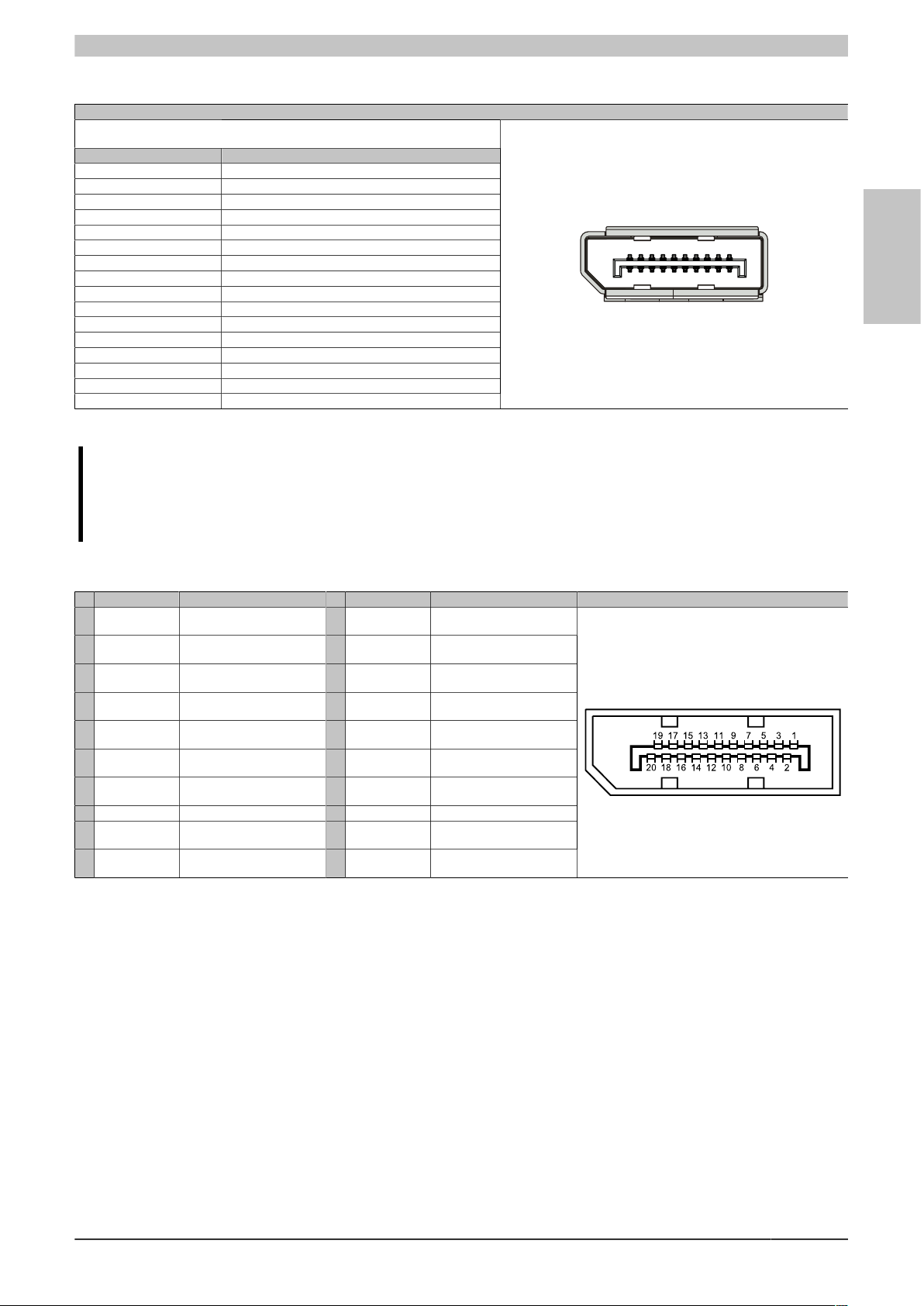
2.4.5 DisplayPort interface
Technical data • Complete system
The following overview lists the video signals available on the DisplayPort output. For
DisplayPort
details, see the technical data for the CPU board being used.
CPU board Video signals with all system unit variants
5PC900.TS17-00 DisplayPort, DVI, HDMI
5PC900.TS17-01 DisplayPort, DVI, HDMI
5PC900.TS17-02 DisplayPort, DVI, HDMI
5PC900.TS17-03 DisplayPort, DVI, HDMI
5PC900.TS17-04 DisplayPort, DVI, HDMI
5PC900.TS77-00 DisplayPort, DVI, HDMI
5PC900.TS77-01 DisplayPort, DVI, HDMI
5PC900.TS77-02 DisplayPort, DVI, HDMI
5PC900.TS77-03 DisplayPort, DVI, HDMI
5PC900.TS77-04 DisplayPort, DVI, HDMI
5PC900.TS77-05 DisplayPort, DVI, HDMI
5PC900.TS77-06 DisplayPort, DVI, HDMI
5PC900.TS77-07 DisplayPort, DVI, HDMI
5PC900.TS77-08 DisplayPort, DVI, HDMI
5PC900.TS77-09 DisplayPort, DVI, HDMI
5PC900.TS77-10 DisplayPort, DVI, HDMI
Table 28: DisplayPort
Information:
The hardware and graphics drivers of approved operating systems support the hot plugging of display
devices to the DisplayPort interface for service purposes. The DisplayPort connector is specified for
10,000 connection cycles.
Chapter 2
Technical data
2.4.5.1 DisplayPort - Pinout
Pin Signal Description Pin Signal Description
1 DP_LANE0+
2 GND Ground 12 DP_LANE3-
3 DP_LANE0-
4 DP_LANE1+
5 GND Ground 15 DP_AUX+
6 DP_LANE1-
7 DP_LANE2+
8 GND Ground 18 DP_HPD# Hot plug detect
9 DP_LANE2-
10 DP_LANE3+
DisplayPort lane 0
(positive)
DisplayPort lane 0
(negative)
DisplayPort lane 1
(positive)
DisplayPort lane 1
(negative)
DisplayPort lane 2
(positive)
DisplayPort lane 2
(negative)
DisplayPort lane 3
(positive)
11 GND Ground
DisplayPort lane 3
(negative)
13 CONFIG1
14 CONFIG2
16 GND Ground
17 DP_AUX-
19 RETURN Return for power
20 DP_PWR Power for connector
Configuration pin 1
(connected to ground)
Configuration pin 2
(connected to ground)
Auxiliary channel
(positive)
Auxiliary channel
(negative)
Table 29: DisplayPort - Pinout
DisplayPort, 20-pin, female
Automation PC 910 user's manual V1.51 69
Page 70
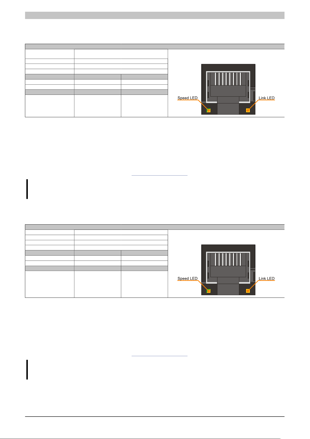
Technical data • Complete system
1
1
2.4.6 Ethernet 1 interface (ETH1)
This Ethernet controller is integrated in the CPU board and connected to external devices via the system unit.
Controller Intel 82579 for 5PC900.TS77-0x
Intel i219 for 5PC900.TS17-0x
Cabling S/STP (Cat 5e)
Transfer rate 10/100/1000 Mbit/s
Cable length Max. 100 m (min. Cat5e)
Speed LED On Off
Green 100 Mbit/s 10 Mbit/s
Orange (light) 1000 Mbit/s -
Link LED On Off
Orange (light) Link (Ethernet network
connection available)
1) The interfaces, etc. available on the device or module have been numbered as such for easy identification. This numbering may differ from that used by
the particular operating system.
2) Switching takes place automatically.
3) The 10 Mbit/s transfer speed / connection only exists if the Link LED is also lit at the same time.
Ethernet 1 interface (ETH11))
RJ45, female
2)
3)
Activity (blinking - da-
ta transfer in progress)
Table 30: Ethernet interface (ETH1)
Driver support
A special driver is required to operate the Ethernet controller. Drivers for approved operating systems are available
in the Downloads section of the B&R website (www.br-automation.com).
Information:
Only download necessary drivers from the B&R website, not from vendor websites.
2.4.7 Ethernet 2 interface (ETH2)
This Ethernet controller is integrated in the mainboard and connected to external devices via the system unit.
Controller Intel® 82574L
Cabling S/STP (Cat 5e)
Transfer rate 10/100/1000 Mbit/s
Cable length Max. 100 m (min. Cat5e)
Speed LED On Off
Green 100 Mbit/s 10 Mbit/s
Orange (light) 1000 Mbit/s -
Link LED On Off
Orange (light) Link (Ethernet network
connection available)
1) The interfaces, etc. available on the device or module have been numbered as such for easy identification. This numbering may differ from that used by
the particular operating system.
2) Switching takes place automatically.
3) The 10 Mbit/s transfer speed / connection only exists if the Link LED is also lit at the same time.
Ethernet 2 interface (ETH21))
RJ45, female
2)
3)
Activity (blinking - da-
ta transfer in progress)
Table 31: Ethernet interface (ETH2)
Driver support
A special driver is required to operate the Ethernet controller. Drivers for approved operating systems are available
in the Downloads section of the B&R website (www.br-automation.com).
Information:
Only download necessary drivers from the B&R website, not from vendor websites.
70 Automation PC 910 user's manual V1.51
Page 71
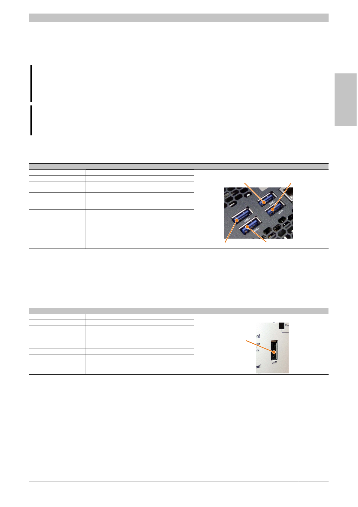
Technical data • Complete system
USB3
USB4
USB2
USB1
USB5
2.4.8 USB interfaces
The APC910 comes equipped with a USB 3.0 (Universal Serial Bus) host controller with multiple USB interfaces,
5 of which are accessible externally for the user. The 4 USB interfaces (USB1-4) on the top are USB 3.0 ports.
The USB interface on the front (USB5) is a USB 2.0 interface.
Warning!
Peripheral USB devices can be connected to the USB interfaces. Due to the large number of USB
devices available on the market, B&R cannot guarantee their functionality. Functionality is ensured
when using the USB devices available from B&R.
Caution!
Because this interface is designed according to general PC specifications, extreme care should be
exercised with regard to EMC, cable routing, etc.
USB1, USB2, USB3, USB4
4 USB 3.0 interfaces are provided on the top of the APC910.
Type USB 2.0 / 3.0
Design Type A
Transfer rate Low speed (1.5 Mbit/s), full speed (12 Mbit/s),
Current load
Cable length
2)
USB1, USB2
USB3, USB4
USB 2.0
USB 3.0
high speed (480 Mbit/s), SuperSpeed (5 Gbit/s)
Universal Serial Bus (USB1, USB2, USB3, USB4)
Max. 1 A
Max. 1 A
Max. 5 m (without hub)
Max. 3 m (without hub)
Table 32: USB1, USB2, USB3, USB4 interface
1) The interfaces, etc. available on the device or module have been numbered as such for easy identification. This numbering may differ from that used by
the particular operating system.
2) Each USB interface is protected by a maintenance-free "USB current-limiting circuit breaker" (max. 1 A).
1)
4x USB type A, female
Chapter 2
Technical data
USB5
A USB 2.0 interface is provided on the APC910 behind the front cover.
Type USB 2.0
Design Type A
Transfer rate Low speed (1.5 Mbit/s), full speed (12 Mbit/s),
Current load
Cable length Max. 5 m (without hub)
2)
USB5
high speed (480 Mbit/s)
Max. 1 A
Universal Serial Bus (USB5)
Table 33: USB5 interface
1) The interfaces, etc. available on the device or module have been numbered as such for easy identification. This numbering may differ from that used by
the particular operating system.
2) The USB interface is protected by a maintenance-free "USB current-limiting circuit breaker" (max. 1 A).
1)
1x USB type A, female
Automation PC 910 user's manual V1.51 71
Page 72
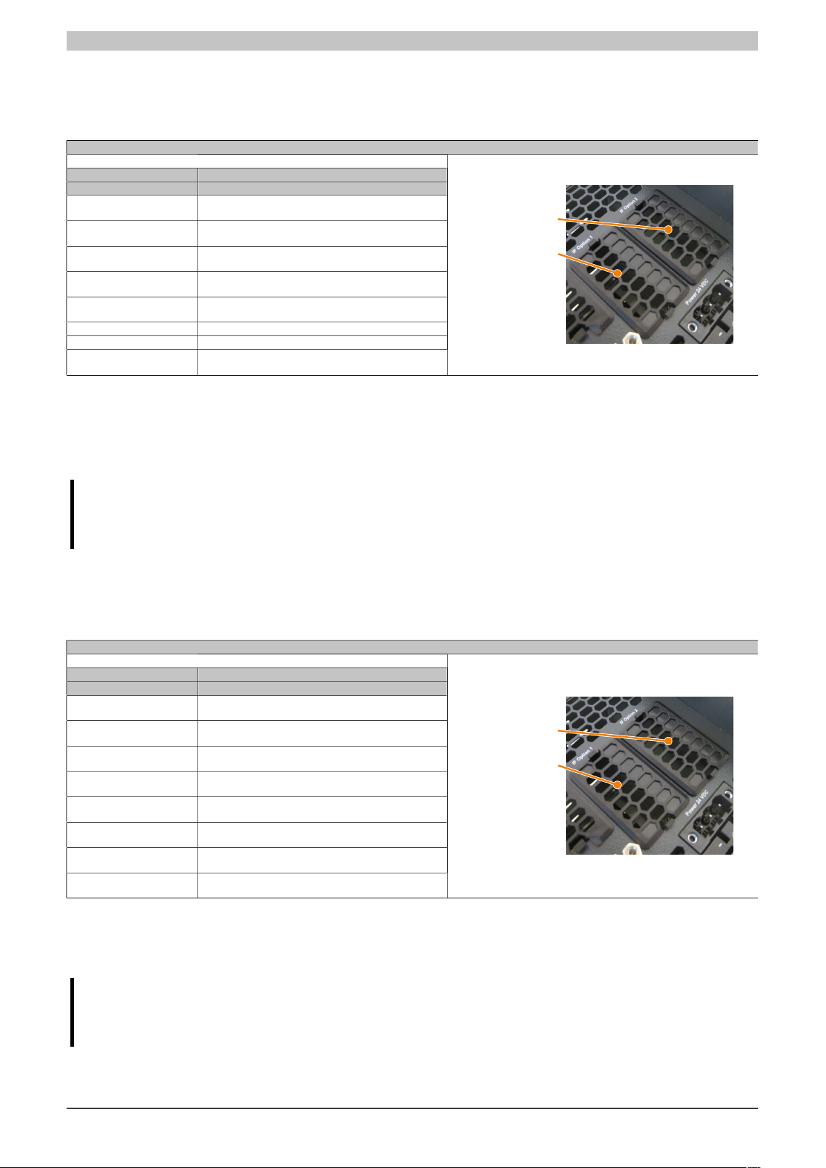
Technical data • Complete system
Interface option 1
Interface option 2
Interface option 1
Interface option 2
2.4.9 IF option 1 slot
Automation PC 910 system units include 2 slots for interface options.
The following table lists the interface options that can be used in the IF option 1 slot.
IF option 1 slot
Model number Short description
5AC901.I485-00
5AC901.ICAN-00
5AC901.ICAN-01
5AC901.IHDA-00 Interface card - 1x audio interface (1x MIC / 1x Line In /
5AC901.IRDY-00 Interface card - Ready relay - For APC910/PPC900/
5AC901.IUPS-00
5AC901.IUPS-01
5AC901.ISIO-00 Interface card - System I/O - For APC910/PPC900/
1)
1)2)
1)2)
3)
4)
Interface option
Interface card - 1x RS232/422/458 interface - For
APC910/PPC900/APC3100/PPC3100
Interface card - 1x CAN interface - For APC910/PPC900/
APC3100/PPC3100
Interface card - 1x CAN interface (SJA1000) - For
APC910/PPC900/APC3100/PPC3100
1x OUT) - For APC910/PPC900/APC3100/PPC3100
APC3100/PPC3100
UPS - For 4.5 Ah battery
UPS - For 2.2 Ah battery
APC3100/PPC3100
Table 34: IF option 1 slot
1) If IF options 5AC901.I485-00 and 5AC901.ICAN-00 are used simultaneously, the 5AC901.ICAN-00 should be installed in the IF option 1 slot and the
5AC901.I485-00 should be installed in the IF option 2 slot.
2) It is not possible to operate two 5AC901.ICAN interface options (in the IF option 1 and IF option 2 slots) at the same time.
3) The 5AC901.IUPS-00 UPS IF option is only permitted to be operated with the 5AC901.BUPS-00 battery unit!
4) The 5AC901.IUPS-01 UPS IF option is only permitted to be operated with the 5AC901.BUPS-01 battery unit!
Information:
For information about installing or replacing an interface option, please refer to section "Installing
interface options" on page 501.
2.4.10 IF option 2 slot
Automation PC 910 system units include 2 slots for interface options.
The following table lists the interface options that can be used in the IF option 2 slot.
IF option 2 slot
Model number Short description
5AC901.I485-00
5AC901.ICAN-00
5AC901.ICAN-01
5AC901.IETH-00 Interface card - 1x ETH 10/100/1000 - For APC910/
5AC901.IPLK-00 Interface card - 1x POWERLINK interface - 2 MB SRAM
5AC901.ISRM-00 Interface card - 2 MB RAM - For APC910/PPC900/
5AC901.IRDY-00 Interface card - Ready relay - For APC910/PPC900/
5AC901.ISIO-00 Interface card - System I/O - For APC910/PPC900/
1)
1)2)
1)2)
Interface option
Interface card - 1x RS232/422/458 interface - For
APC910/PPC900/APC3100/PPC3100
Interface card - 1x CAN interface - For APC910/PPC900/
APC3100/PPC3100
Interface card - 1x CAN interface (SJA1000) - For
APC910/PPC900/APC3100/PPC3100
PPC900/APC3100/PPC3100
- For APC910/PPC900/APC3100/PPC3100
APC3100/PPC3100
APC3100/PPC3100
APC3100/PPC3100
Table 35: IF option 2 slot
1) If IF options 5AC901.I485-00 and 5AC901.ICAN-00 are used simultaneously, the 5AC901.ICAN-00 should be installed in the IF option 1 slot and the
5AC901.I485-00 should be installed in the IF option 2 slot.
2) It is not possible to operate two 5AC901.ICAN interface options (in the IF option 1 and IF option 2 slots) at the same time.
Information:
72 Automation PC 910 user's manual V1.51
For information about installing or replacing an interface option, please refer to section "Installing
interface options" on page 501.
Page 73
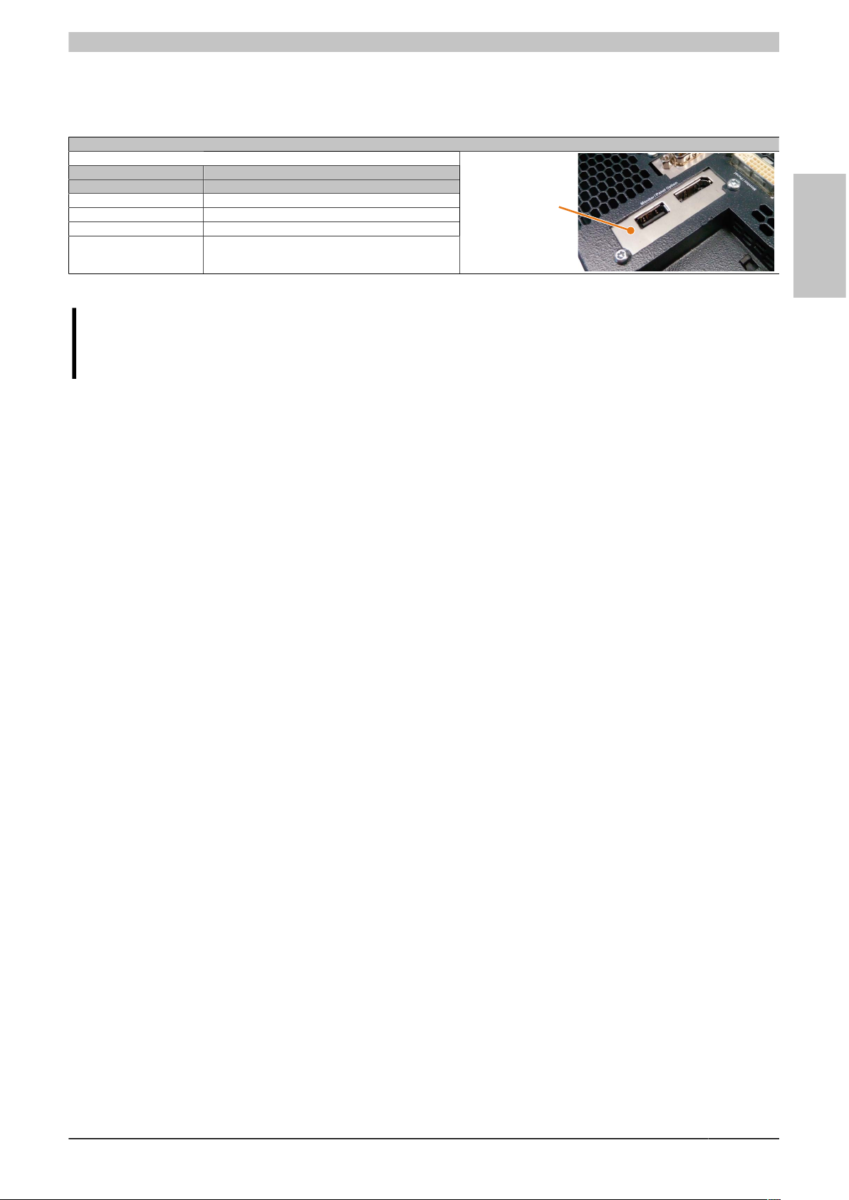
Technical data • Complete system
Monitor/Panel option
2.4.11 Monitor/Panel option
2-slot (5PC910.SX02-00) and 5-slot (5PC910.SX05-00) APC910 variants allow a third graphics line to be set up.
There are a variety of monitor/panel options available for this.
Monitor/Panel option
Model number Short description
Monitor/Panel options
5AC901.LDPO-00 DisplayPort transmitter
5AC901.LSDL-00 Smart Display Link / DVI transmitter
5AC901.LSD3-00 SDL3 transmitter
5AC901.LSD4-00 SDL4 transmitter
Table 36: Monitor/Panel option
Information:
For information about installing or replacing a monitor/panel option, please refer to the section "In-
stalling monitor/panel options" on page 504.
Chapter 2
Technical data
Automation PC 910 user's manual V1.51 73
Page 74

Technical data • Complete system
177.7
106.7
9
25.8
9
5517.4
100.5
167.65
8.25
106.65
15
49.65
57.15
3.65
11.65
111.15
59.05
100.36
2.4.12 Card slot (PCI/PCIe)
Standard PCI 2.2 half-size cards or PCI Express (PCIe) half-size cards can be installed depending on the type of
bus unit. They must not exceed the following dimensions.
Figure 24: Standard half-size 32-bit PCI card - Dimensions
Figure 25: Standard half-size PCIe card - Dimensions
Information:
For information about installing or replacing a PCI/PCIe card, please refer to section "Installing PCI/
PCIe cards" on page 513.
74 Automation PC 910 user's manual V1.51
Page 75
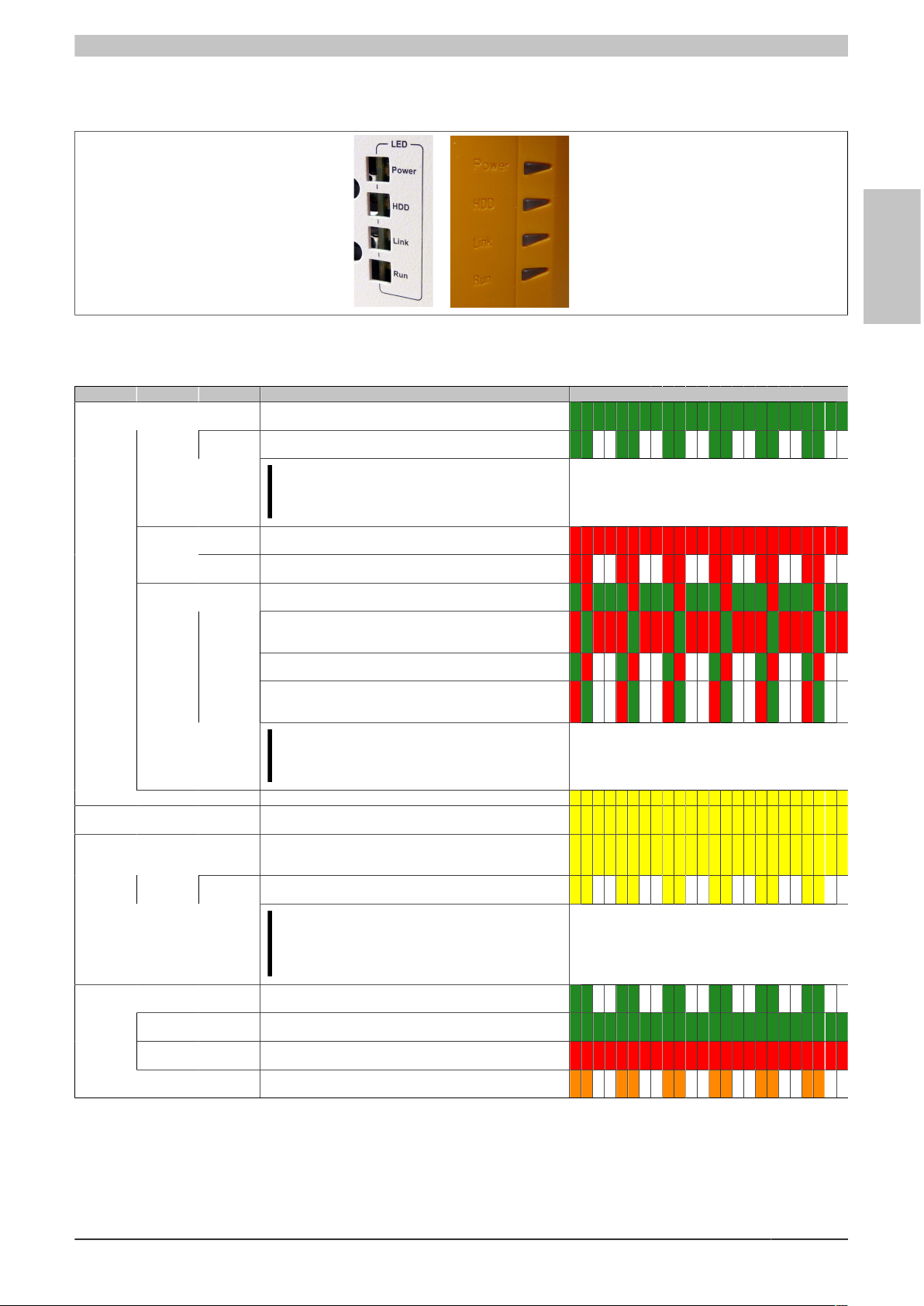
Technical data • Complete system
2.4.13 LED status indicators
LED status indicators are located on the front of the system unit.
The following timing is used for the LED status indicators:
Block size: 250 ms
Repeat interval: 500 ms, 2 boxes thus represent one interval
LED Color Status Function LED status indicators
Power
Green
On Voltage supply OK
Chapter 2
Technical data
Blinking
Device booted, battery status "BAD"
Information:
For more information, see "Battery" on page 77.
Red
Red/Green Blinking
On System in standby mode (S5: Soft-off mode or S4: Hibernation
mode suspend-to-disk)
Blinking MTCX running, battery status "BAD". System in standby mode
(S5: Soft-off mode or S4: Hibernation mode suspend-to-disk)
Faulty or incomplete BIOS, MTCX or I/O FPGA update, battery
status OK, voltage supply OK
Faulty or incomplete BIOS, MTCX or I/O FPGA update, battery
status OK, standby mode (S5: Soft-off mode or S4: Hibernation mode suspend-to-disk)
Faulty or incomplete BIOS, MTCX or I/O FPGA update, battery
status BAD, voltage supply OK
Faulty or incomplete BIOS, MTCX or I/O FPGA update, battery
status BAD, standby mode (S5: Soft-off mode or S4: Hibernation mode suspend-to-disk)
Information:
An update must be performed again.
HDD Yellow On Indicates drive access (HDD, CFast)
Link Yellow
Yellow On Voltage supply not OK, system operating from UPS
On Indicates an active SDL connection on the male panel connec-
Blinking
tor
Indicates that an active SDL connection has been interrupted
by a loss of power to the display unit
Information:
Check the voltage supply / power connector of the
connected display unit.
Run
Automation PC 910 user's manual V1.51 75
Green Blinking Automation Runtime booting
Controlled by Automation Runtime (ARemb and ARwin)
Green On Application running
Controlled by Automation Runtime (ARemb and ARwin)
Red On Application in service mode
Controlled by Automation Runtime (ARemb and ARwin)
Orange Blinking Indicates a licensing violation
Table 37: LED status indicators - Data
Page 76
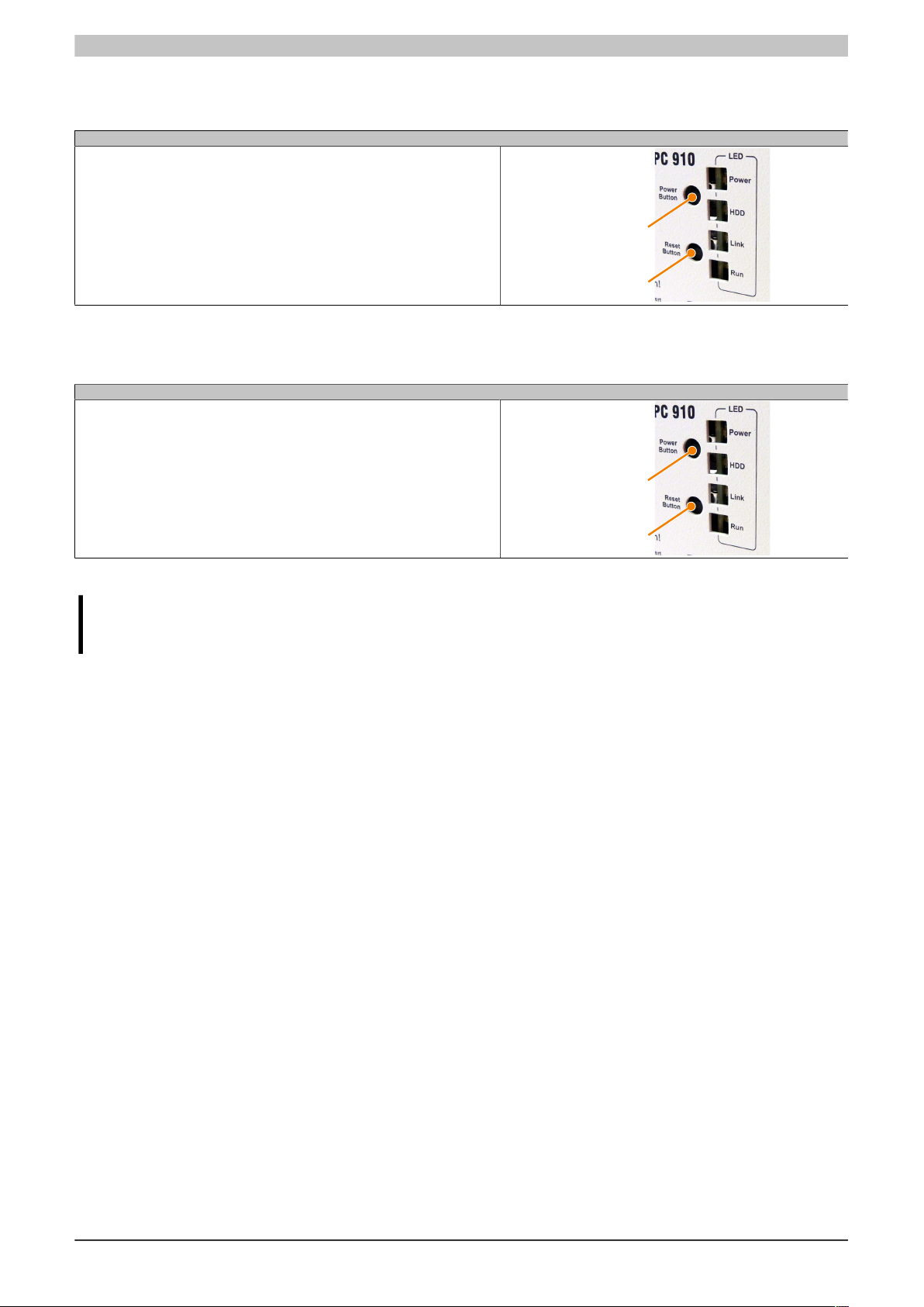
Technical data • Complete system
Power button
Reset button
Power button
Reset button
2.4.14 Power button
The power button provides a wide range of ATX power supply functions.
The power button can be pressed with a pointed object (e.g. paper clip or tip of a pen).
The power button behaves like the power switch on a current desktop PC with an ATX
power supply:
Press and release ... Switches on the Panel PC, performs the action configured in
the operating system for when the power button is pressed (shutdown, sleep, etc.) or
switches off the Automation PC.
Press and hold ... The ATX power supply switches off the without shutting down the
operating system (approx. 4 s - possible data loss!).
Pressing the power button does not reset the MTCX processor.
Power button
Table 38: Power button
2.4.15 Reset button
The reset button can be pressed with a pointed object (e.g. paper clip or tip of a pen).
Pushing the reset button triggers a hardware and PCI reset. The APC910 is restarted
(cold restart - possible data loss!).
Pressing the reset button does not reset the MTCX processor.
Reset button
Table 39: Reset button
Warning!
A system reset can result in lost data!
76 Automation PC 910 user's manual V1.51
Page 77
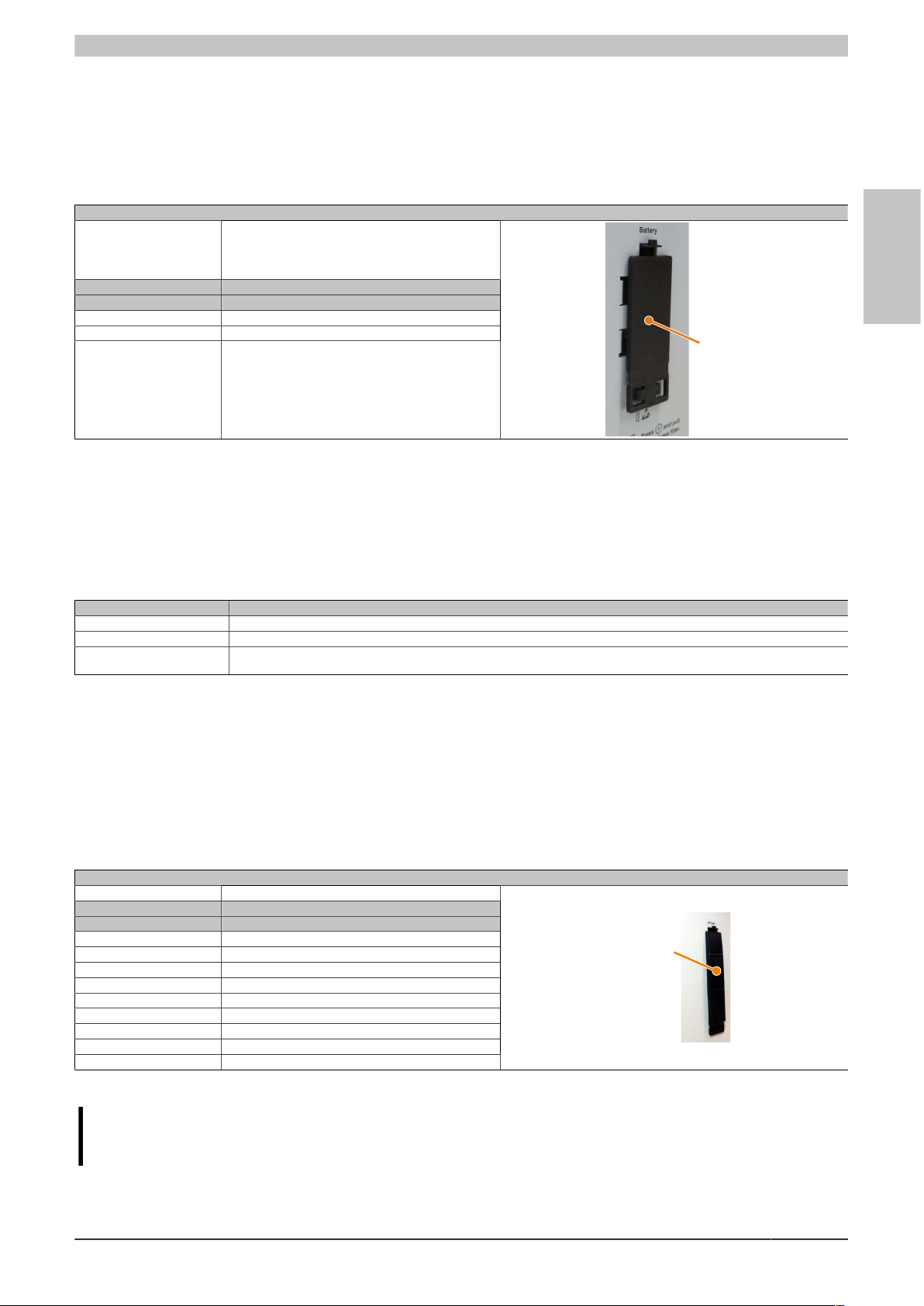
Technical data • Complete system
Battery
CFast slot
2.4.16 Battery
The lithium battery (3 V, 950 mAh) buffers the internal real-time clock (RTC). It is located behind the black cover
on the front of the device. The battery's buffer time is at least 4 years (at 50°C, 8.5 μA for the components being
supplied and a self-discharge of 40%). If an SRAM interface option has been installed, this lifespan is reduced
to 2½ years. The battery has a limited service life and should be replaced regularly (after the specified service
life at the latest).
Battery
Type
Removable
Service life
Model number Short description
Batteries
0AC201.91 Lithium batteries, 4 pcs., 3 V / 950 mAh, button cell
4A0006.00-000 Lithium battery, 1 pc., 3 V / 950 mAh, button cell
1) At 50°C, 8.5 µA of the supplied components and a self-discharge of 40%. If an SRAM interface option has been installed, the service life is 2½ years.
Renata 950 mAh
Yes, accessible from the outside
4 years
1)
Battery
Table 40: Battery
Chapter 2
Technical data
The status of the battery is determined immediately after the device is started and subsequently checked by the
system every 24 hours. During this measurement, the battery is subjected to a brief load (approximately 1 second)
and then evaluated. Once determined, the battery status is displayed in BIOS (Advanced - OEM features - System
board features - Voltage values) and in the B&R Control Center (ADI driver); it can also be read in a customer
application using the ADI library.
Battery status Function
N/A The hardware or firmware being used is too old and does not support reading the battery status.
GOOD Data buffering is intact.
BAD From the point when battery capacity is recognized as insufficient (BAD), data buffering is intact for approximately another 500
hours.
Table 41: Battery status
From the point when battery capacity is recognized as insufficient, data buffering is intact for approximately another
500 hours. When replacing the battery, data is buffered for approximately 10 minutes by a gold leaf capacitor.
2.4.17 CFast slot
The APC910 offers an easy-to-access CFast slot behind its front cover so that a CFast card can be used as
removable media for transferring data or performing upgrades.
This CFast slot is connected to the chipset internally via SATA 1 with SATA III design (SATA 6 Gbit/s).
Connection SATA 1
Model number Short description
CFast cards
5CFAST.2048-00 CFast card, 2 GB SLC
5CFAST.4096-00 CFast card, 4 GB SLC
5CFAST.8192-00 CFast card, 8 GB SLC
5CFAST.016G-00 CFast card, 16 GB SLC
5CFAST.032G-00 CFast card, 32 GB SLC
5CFAST.032G-10 CFast card, 32 GB MLC
5CFAST.064G-10 CFast card, 64 GB MLC
5CFAST.128G-10 CFast card, 128 GB MLC
5CFAST.256G-10 CFast card, 256 GB MLC
CFast slot
Table 42: CFast slot
Warning!
The CFast card is only permitted to be connected or disconnected when the power is switched off.
Automation PC 910 user's manual V1.51 77
Page 78
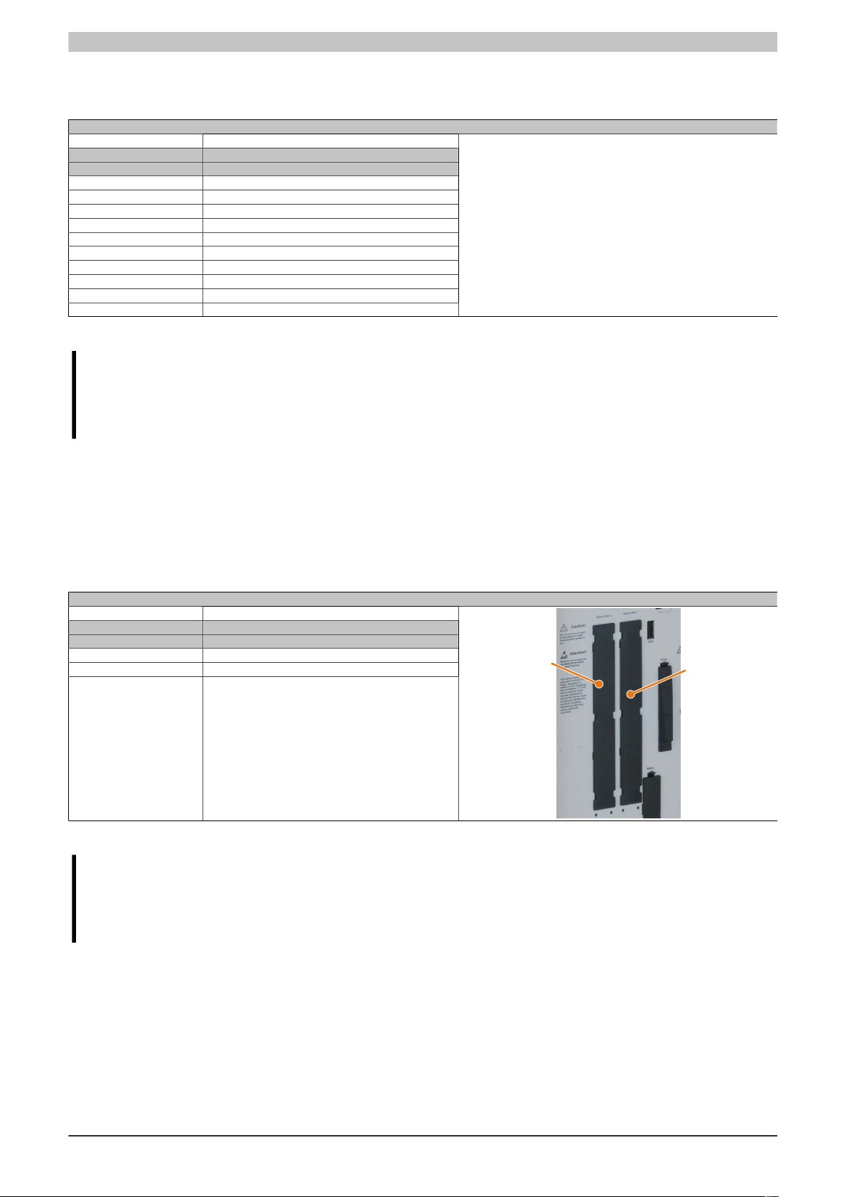
Technical data • Complete system
Slide-in slot 2
Slide-in slot 1
2.4.18 Slide-in compact slot
The slide-in compact slot is connected to the chipset internally via SATA 0 with SATA III design (SATA 6 Gbit/s).
Connection SATA 0
Model number Short description
Drives
5AC901.CHDD-00 250 GB hard disk - Slide-in compact - SATA
5AC901.CHDD-01 500 GB hard disk - Slide-in compact - SATA
5AC901.CSSD-00 32 GB SSD (SLC) - Slide-in compact - SATA
5AC901.CSSD-01 60 GB SSD (MLC) - Slide-in compact - SATA
5AC901.CSSD-02 180 GB SSD (MLC) - Slide-in compact - SATA
5AC901.CSSD-03 60 GB SSD (MLC) - Slide-in compact - SATA
5AC901.CSSD-04 128 GB SSD (MLC) - Slide-in compact - SATA
5AC901.CSSD-05 256 GB SSD (MLC) - Slide-in compact - SATA
5AC901.CSSD-06 512 GB SSD (MLC) - Slide-in compact - SATA
5AC901.CCFA-00 CFast adapter - For slide-in compact slot
Slide-in compact slot
Table 43: Slide-in compact slot
Information:
The slide-in compact slot cannot be accessed from the outside. The side panel must be removed in
order to replace a drive. For information about installing or replacing a slide-in compact drive, please
refer to the section "Installing and exchanging slide-in compact drives" on page 507.
2.4.19 Slide-in slot 1
Slide-in slot 1 is available on the 2-slot system unit (5PC910.SX02-00) and 5-slot system unit (5PC910.SX05-00).
It is connected to the chipset internally via SATA 2 and USB and available in the following version depending on
the CPU board:
•
SATA II version (SATA 3 Gbit/s) for TS77 CPU boards
•
SATA III version (SATA 6 Gbit/s) for TS17 CPU boards
Connection SATA 2 and USB
Model number Short description
Drives
5AC901.SDVW-00 DVD drive - DVD-R/RW|DVD+R/RW - Slide-in
5AC901.SSCA-00 Slide-in compact adapter - For slide-in compact drives
Slide-in slot 1
Table 44: Slide-in slot 1
Information:
The slide-in slot cannot be accessed from the outside. The side panel must be removed in order to
replace a drive. For information about installing or replacing a slide-in drive, please refer to the section
"Installing and exchanging slide-in drives" on page 510.
78 Automation PC 910 user's manual V1.51
Page 79
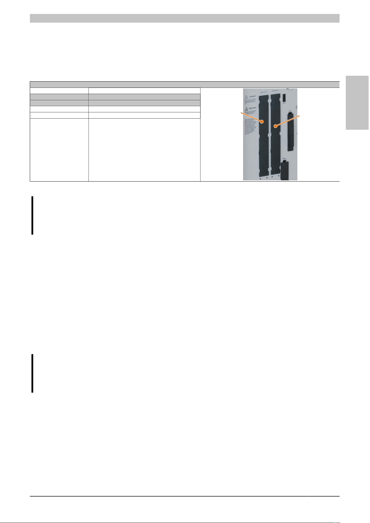
Technical data • Complete system
Slide-in slot 2
Slide-in slot 1
2.4.20 Slide-in slot 2
Slide-in slot 2 is only available on the 5-slot system unit (5PC910.SX05-00). It is connected to the chipset internally
via SATA 3 and USB and available in the following version depending on the CPU board:
•
SATA II version (SATA 3 Gbit/s) for TS77 CPU boards
•
SATA III version (SATA 6 Gbit/s) for TS17 CPU boards
Connection SATA 3 and USB
Slide-in slot 2
Model number Short description
Drives
5AC901.SDVW-00 DVD drive - DVD-R/RW|DVD+R/RW - Slide-in
5AC901.SSCA-00 Slide-in compact adapter - For slide-in compact drives
Table 45: Slide-in slot 2
Information:
The slide-in slot cannot be accessed from the outside. The side panel must be removed in order to
replace a drive. For information about installing or replacing a slide-in drive, please refer to the section
"Installing and exchanging slide-in drives" on page 510.
2.4.21 Trusted Platform Module (TPM)
Depending on the configuration ordered, a Trusted Platform Module (TPM 2.0) is installed on the CPU board. A
TPM is a chip that adds important security functions to your device, e.g. improved protection of the PC against
unauthorized manipulation by third parties. Current operating systems, e.g. Windows 10, support these security
functions.
Chapter 2
Technical data
Enabling the Trusted Platform Module
The TPM is disabled by default in BIOS and can be enabled in BIOS under "Advanced" and "Trusted computing".
Follow the instructions in BIOS Setup.
Using the Trusted Platform Module
The TPM can be used together with "BitLocker" drive encryption in Windows 10, for example. To do this, follow
the instructions in the operating system.
Information:
If the password for data encryption is lost, it is not possible to decrypt the data, e.g. after a BIOS
update. Access to the encrypted drive is lost. Passwords must be carefully stored and protected from
unauthorized access.
Automation PC 910 user's manual V1.51 79
Page 80
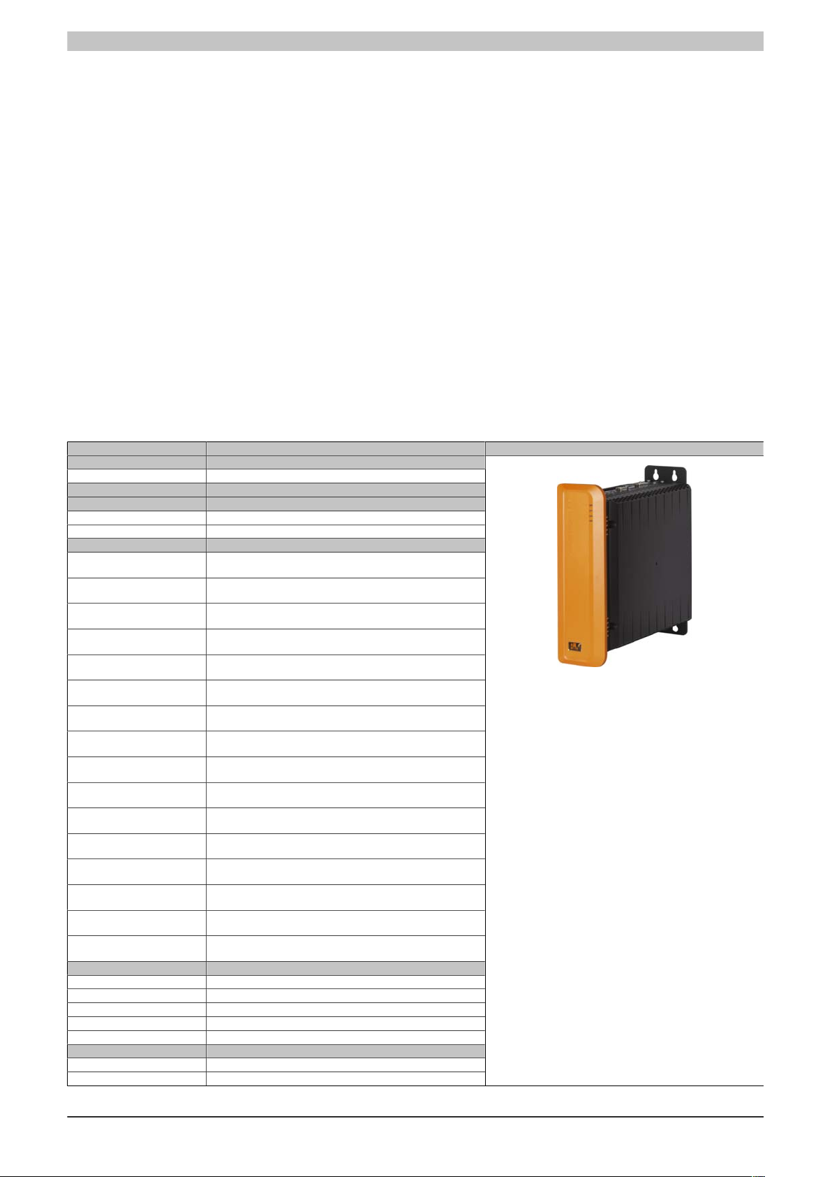
Technical data • Individual components
3 Individual components
3.1 System units
The system unit unites all of the individual components into one compact device. It consists of a housing and an
integrated mainboard. Interfaces are easily accessible either on top of the device or behind the orange cover on
the front. System units have either 1, 2 or 5 card slots.
The front cover is not included with the system unit and must be ordered separately, see "Front covers" on page
223.
3.1.1 5PC910.SX01-00
3.1.1.1 General information
•
Slot for a bus unit with 1 PCI or 1 PCIe slot
•
Insert for 1 slide-in compact drive
•
Insert for 2 interface options
•
SDL/DVI/Monitor and DisplayPort interfaces
•
CFast slot
3.1.1.2 Order data
Model number Short description Figure
5PC910.SX01-00 1-slot APC910 system unit
5AC901.BX01-00 APC910 1-slot bus - 1 PCI
5AC901.BX01-01 APC910 1-slot bus - 1 PCI Express x8
5PC900.TS17-00 CPU board Intel Core i5 6440EQ - Quad core - Chipset QM170
5PC900.TS17-01 CPU board Intel Core i3 6100E - Dual core - Chipset HM170 -
5PC900.TS17-02 CPU board Intel Celeron G3900E - Dual core - Chipset HM170
5PC900.TS17-03 CPU Board Intel Xeon E3-1515MV5 - Quad core - Chipset
5PC900.TS17-04 CPU board Intel Core i7 6820EQ - Quad core - Chipset QM170
5PC900.TS77-00 CPU board Intel Core i7 3615QE 2.3 GHz - Quad core - Chipset
5PC900.TS77-01 CPU board Intel Core i7 3612QE 2.1 GHz - Quad core - Chipset
5PC900.TS77-02 CPU board Intel Core i7 3555LE 2.5 GHz - Dual core - Chipset
5PC900.TS77-03 CPU board Intel Core i7 3517UE 1.7 GHz - Dual core - Chipset
5PC900.TS77-04 CPU board Intel Core i5 3610ME 2.7 GHz - Dual core - Chipset
5PC900.TS77-05 CPU board Intel Core i3 3120ME 2.4 GHz - Dual core - Chipset
5PC900.TS77-06 CPU board Intel Core i3 3217UE 1.6 GHz - Dual core - Chipset
5PC900.TS77-07 CPU board Intel Celeron 847E 1.1 GHz - Dual core - HM76
5PC900.TS77-08 CPU board Intel Celeron 827E 1.4 GHz - Single core - HM76
5PC900.TS77-09 CPU board Intel Celeron 1020E 2.2 GHz - Dual core - HM76
5PC900.TS77-10 CPU board Intel Celeron 1047UE 1.4 GHz - Dual core - HM76
5AC901.HS00-00 APC910 heat sink, active
5AC901.HS00-01 APC910 active heat sink QM170/HM170
5AC901.HS00-02 APC910 active heat sink CM236
5AC901.HS01-00 APC910 heat sink, passive
5AC901.HS01-01 APC910 passive heat sink QM170/HM170
5MMDDR.016G-04 SO-DIMM DDR4, 16384 MB
5MMDDR.1024-03 SO-DIMM DDR3, 1024 MB
System units
Required accessories
Bus units
CPU boards
- 2.7 GHz active - For APC910
2.7 GHz active, 1.9 GHz passive - For APC910
- 2.4 GHz active, 1.7 GHz passive - For APC910
CM236 - 2.8 GHz active - For APC910
- 2.8 GHz active - For APC910
QM77 - For APC910
QM77 - For APC910
QM77 - For APC910
QM77 - For APC910
QM77 - For APC910
QM77 - For APC910
QM77 - For APC910
chipset - For APC910
chipset - For APC910
chipset - For APC910
chipset - For APC910
Heat sink
Main memory
Table 46: 5PC910.SX01-00 - Order data
80 Automation PC 910 user's manual V1.51
Page 81
Technical data • Individual components
Model number Short description Figure
5MMDDR.2048-03 SO-DIMM DDR3, 2048 MB
5MMDDR.4096-03 SO-DIMM DDR3, 4096 MB
5MMDDR.4096-04 SO-DIMM DDR4, 4096 MB
5MMDDR.8192-03 SO-DIMM DDR3, 8192 MB
5MMDDR.8192-04 SO-DIMM DDR4, 8192 MB
Terminal blocks
0TB103.9 Connector 24 VDC - 3-pin female - Screw clamp terminal block
3.31 mm²
0TB103.91 Connector 24 VDC - 3-pin female - Cage clamp terminal block
3.31 mm²
Optional accessories
Drives
5AC901.CCFA-00 CFast adapter - For slide-in compact slot
5AC901.CHDD-01 500 GB hard disk - Slide-in compact - SATA
5AC901.CSSD-04 128 GB SSD MLC - Slide-in compact - SATA
5AC901.CSSD-05 256 GB SSD MLC - Slide-in compact - Toshiba - SATA
5AC901.CSSD-06 512 GB SSD MLC - Slide-in compact - Toshiba - SATA
Fan kit
5AC901.FA01-00 APC910 fan kit - For 5PC910.SX01-00
Front cover
5AC901.FF01-00 Front cover for 1-slot APC910 - Orange
5AC901.FF01-01 Front cover for 1-slot APC910 - Dark gray
5AC901.FF01-02 Front cover for 1-slot APC910 - Dark gray - Without logo
5AC901.FF01-03 Front cover for 1-slot APC910 - Orange - Without logo
Interface options
5AC901.I485-00 Interface card - 1x RS232/422/485 interface - For APC910/
PPC900/APC3100/PPC3100
5AC901.ICAN-00 Interface card - 1x CAN interface - For APC910/PPC900/
APC3100/PPC3100
5AC901.ICAN-01 Interface card - 1x CAN interface (SJA1000) - For APC910/
PPC900/APC3100/PPC3100
5AC901.IETH-00 Interface card - 1x ETH 10/100/1000 - For APC910/PPC900/
APC3100/PPC3100
5AC901.IHDA-00 Interface card - 1x audio interface (1x MIC / 1x Line In / 1x OUT)
- For APC910/PPC900/APC3100/PPC3100
5AC901.IPLK-00 Interface card - 1x POWERLINK interface - 2 MB SRAM - For
APC910/PPC900/APC3100/PPC3100
5AC901.IRDY-00 Interface card - Ready relay - For APC910/PPC900/APC3100/
PPC3100
5AC901.ISIO-00 Interface card - System I/O - For APC910/PPC900/APC3100/
PPC3100
5AC901.ISRM-00 Interface card - 2 MB RAM - For APC910/PPC900/APC3100/
PPC3100
Uninterruptible power supplies
5AC901.IUPS-00 UPS - For 4.5 Ah battery
5AC901.IUPS-01 UPS - For 2.2 Ah battery
Table 46: 5PC910.SX01-00 - Order data
Chapter 2
Technical data
3.1.1.3 Technical data
Information:
The following specifications, properties and limit values apply only to this individual component and
may deviate from those that apply to the complete system. For the complete system in which this
individual component is used, for example, the data specified for that complete system applies.
Model number 5PC910.SX01-00
General information
Cooling Passive via heat sink and optionally supported with an active fan kit
LED status indicators Power, HDD, Link, Run
B&R ID code 0xD6DA
Battery
Type Renata 950 mAh
Service life 4 years
Removable Yes, accessible behind the front cover
Design Lithium ion
Power button Yes
Reset button Yes
Buzzer Yes
Table 47: 5PC910.SX01-00 - Technical data
Automation PC 910 user's manual V1.51 81
1)
Page 82
Technical data • Individual components
Model number 5PC910.SX01-00
Certifications
CE Yes
UL cULus E115267
DNV GL Temperature: B (0 - 55°C)
GOST-R Yes
Controller
Boot loader BIOS
Real-time clock
Battery-backed Yes
Power failure logic
Controller MTCX
Buffer time 10 ms
Memory
Type Depends on the CPU board being used
Memory size Depends on the CPU board being used
Graphics
Controller Depends on the CPU board being used
Interfaces
COM1
Type RS232, modem supported, not electrically isolated
Design DSUB, 9-pin, male
UART 16550-compatible, 16-byte FIFO
Max. baud rate 115 kbit/s
CFast slot
Quantity 1
Type SATA III (SATA 60 Gbit/s)
USB
Quantity 5
Type 4x USB 3.0 (top)
Design Type A
Transfer rate Low speed (1.5 Mbit/s), full speed (12 Mbit/s), high speed (480 Mbit/s), SuperSpeed (5 Gbit/s)
Current-carrying capacity Max. 1 A per connection
Ethernet
Quantity 2
Design Shielded RJ45
Transfer rate 10/100/1000 Mbit/s
Max. baud rate 1 Gbit/s
DisplayPort
Quantity 1
Version Depends on the CPU board being used
Panel/Monitor interface
Design DVI-I
Type SDL/DVI/Monitor
Inserts
PCI/PCIe slots
Quantity 1 PCI slot or 1 PCIe slot
Slide-in drives
Quantity Slide-in compact drives
Quantity 1
Type SATA III (SATA 60 Gbit/s)
Interface option 2
Monitor/Panel option No
Add-on UPS slot Yes
Insert for fan kit Yes
Electrical characteristics
Nominal voltage 24 VDC ±25%, SELV
Nominal current Max. 5.5 A
Inrush current Max. 60 A for <300 μs
Overvoltage category per EN 61131-2 II
Electrical isolation Yes
Operating conditions
Pollution degree per EN 61131-2 Pollution degree 2
Degree of protection per EN 60529 IP20
Table 47: 5PC910.SX01-00 - Technical data
Industrial control equipment
Humidity: B (up to 100%)
Vibration: A (0.7 g)
EMC: B (Bridge and open deck)
3)
1x USB 2.0 (front)
5)
6)
7)
8)
9)
2)
4)
82 Automation PC 910 user's manual V1.51
Page 83
Technical data • Individual components
Model number 5PC910.SX01-00
Environmental conditions
Temperature
Operation Component-dependent
Storage -20 to 60°C
Transport -20 to 60°C
Relative humidity
Operation Component-dependent
Storage Component-dependent
Transport Component-dependent
11)
Vibration
Operation (continuous) 2 to 9 Hz: 1.75 mm amplitude / 9 to 200 Hz: 0.5 g
Operation (occasional) 2 to 9 Hz: 3.5 mm amplitude / 9 to 200 Hz: 1 g
Storage 2 to 8 Hz: 7.5 mm amplitude / 8 to 200 Hz: 2 g / 200 to 500 Hz: 4 g
Transport 2 to 8 Hz: 7.5 mm amplitude / 8 to 200 Hz: 2 g / 200 to 500 Hz: 4 g
11)
Shock
Operation 15 g, 11 ms
Storage 30 g, 6 ms
Transport 30 g, 6 ms
Elevation
Operation -300 to 3000 m above sea level
Mechanical characteristics
13)
Housing
Material Galvanized plate, plastic
Coating Anthracite gray
Dimensions
Width 91 mm
Height 270 mm
Depth 254.75 mm
Weight 2050 g
Table 47: 5PC910.SX01-00 - Technical data
1) At 50°C, 8.5 µA for the components being supplied and self-discharge of 40%. If an interface option with SRAM or POWERLINK is installed, the service
life is 2½ years.
2) Yes, although applies only if all components installed in the complete system have this certification and are listed on the associated DNV GL certificate for
the product family.
3) Maintenance Controller Extended
4) The SuperSpeed transfer rate (5 Gbit/s) is only possible with USB 3.0.
5) The PCI and PCIe slots available depend on the 5AC901.BX01-00 and 5AC901.BX01-01 bus unit being used.
6) The UPS module can only be operated in the IF option 1 slot.
7) EN 60950 requirements must be observed; see section "+24 VDC power supply" of the user's manual.
8) Maximum current consumption (24 V / 130 W). This can vary depending on the configuration (see "Power calculation" section). The inrush current must also
be taken into consideration when selecting the power supply.
9) Only when all interface covers and the front cover are closed.
10) For detailed information, see the temperature tables in the user's manual.
11) Maximum values unless specified otherwise by another individual component. Vibration testing is performed per EN 60068-2-6. Shock testing is performed
per EN 60068-2-27.
12) The maximum ambient temperature is typically derated by 1°C per 1000 meters starting at 500 meters above sea level.
13) There may be visible deviations in the color and surface appearance depending on the process or batch.
10)
12)
Chapter 2
Technical data
Automation PC 910 user's manual V1.51 83
Page 84
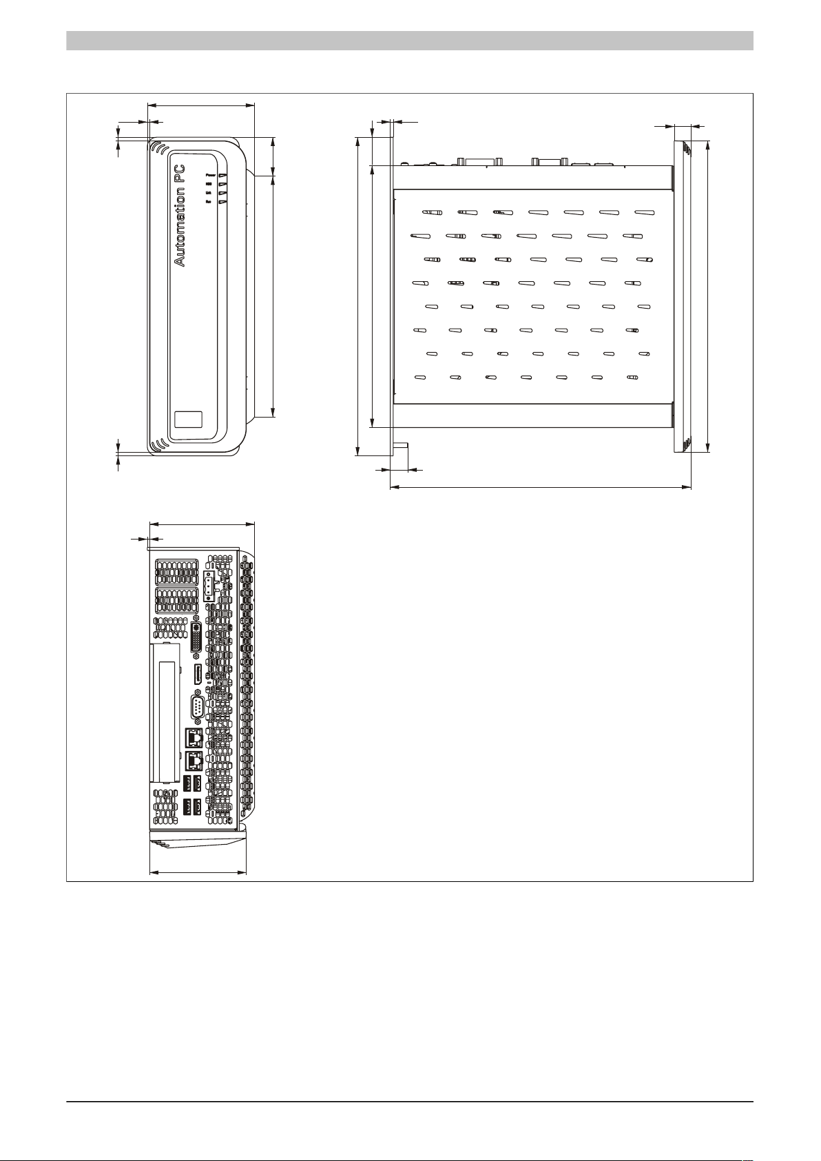
3
3
1.95
91
33
204
82
89
2
254.75
15
2.5
14
270
222
24
264
Technical data • Individual components
3.1.1.4 Dimensions
Figure 26: 5PC910.SX01-00 - Dimensions
84 Automation PC 910 user's manual V1.51
Page 85
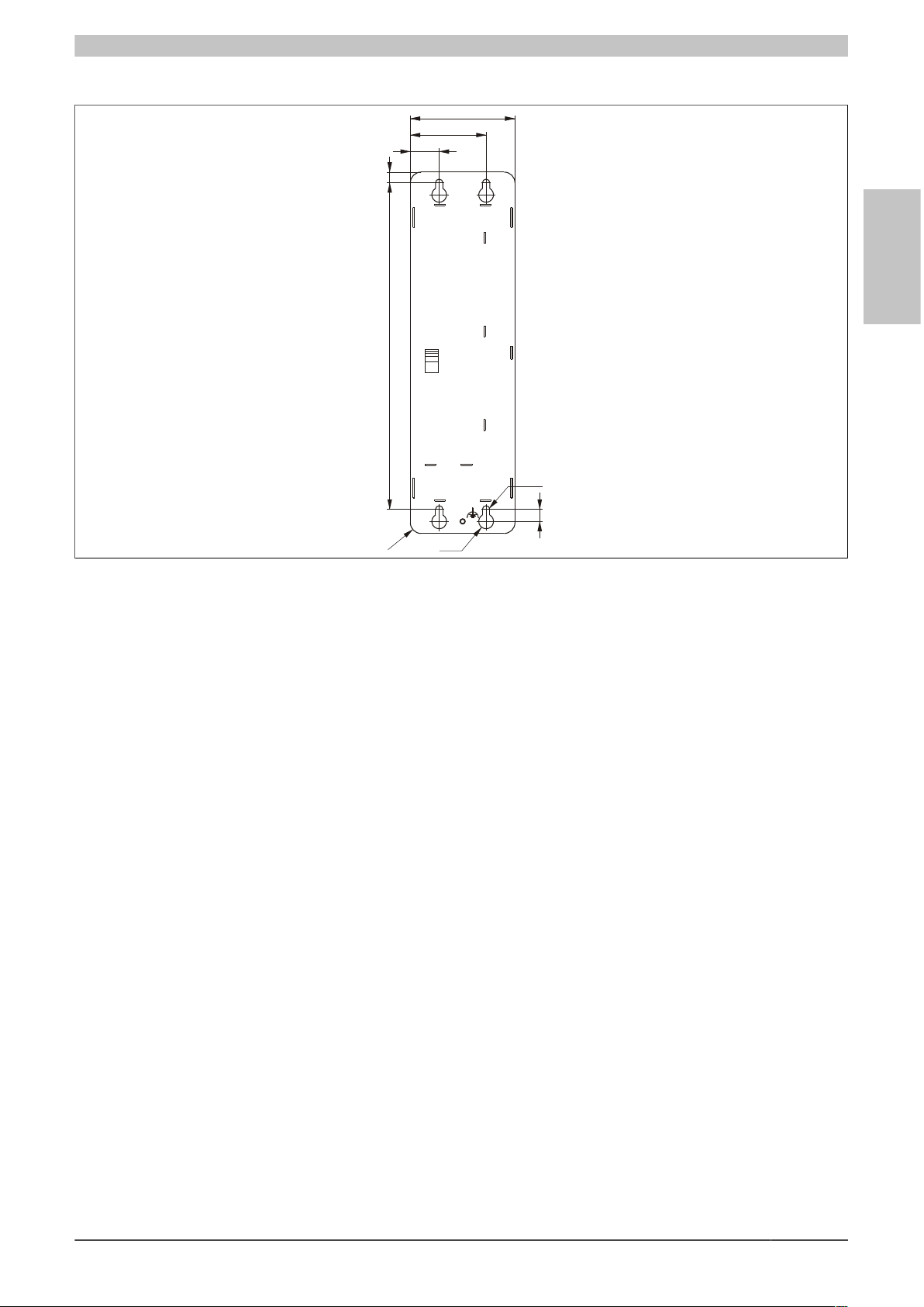
3.1.1.5 Drilling template
21.5
56.5
78
244 8
ø5.5
9
ø11
R8
Technical data • Individual components
Chapter 2
Technical data
Figure 27: 5PC910.SX01-00 - Drilling template
Automation PC 910 user's manual V1.51 85
Page 86
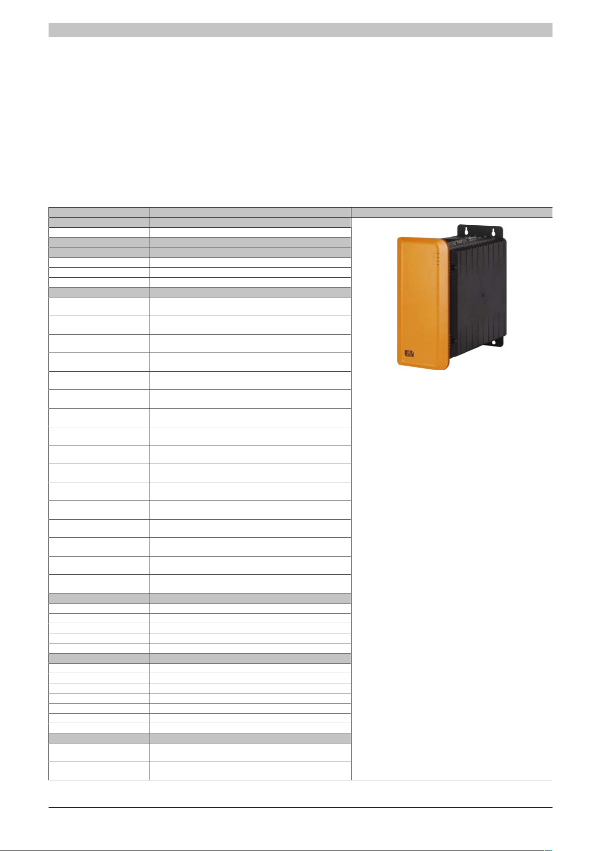
Technical data • Individual components
3.1.2 5PC910.SX02-00
3.1.2.1 General information
•
Slot for a bus unit with 2 PCI slots or 1 PCI and 1 PCIe slots
•
Insert for 1 slide-in compact drive and 1 slide-in drive
•
Insert for 2 interface options
•
SDL/DVI/Monitor and DisplayPort interfaces
•
Insert for monitor/panel option
•
CFast slot
3.1.2.2 Order data
Model number Short description Figure
5PC910.SX02-00 2-slot APC910 system unit
5AC901.BX02-00 APC910 2-slot bus - 2 PCI
5AC901.BX02-01 APC910 2-slot bus - 1 PCI - 1 PCI Express x8
5AC901.BX02-02 APC910 2-slot bus - 2 PCI Express x4
5PC900.TS17-00 CPU board Intel Core i5 6440EQ - Quad core - Chipset QM170
5PC900.TS17-01 CPU board Intel Core i3 6100E - Dual core - Chipset HM170 -
5PC900.TS17-02 CPU board Intel Celeron G3900E - Dual core - Chipset HM170
5PC900.TS17-03 CPU Board Intel Xeon E3-1515MV5 - Quad core - Chipset
5PC900.TS17-04 CPU board Intel Core i7 6820EQ - Quad core - Chipset QM170
5PC900.TS77-00 CPU board Intel Core i7 3615QE 2.3 GHz - Quad core - Chipset
5PC900.TS77-01 CPU board Intel Core i7 3612QE 2.1 GHz - Quad core - Chipset
5PC900.TS77-02 CPU board Intel Core i7 3555LE 2.5 GHz - Dual core - Chipset
5PC900.TS77-03 CPU board Intel Core i7 3517UE 1.7 GHz - Dual core - Chipset
5PC900.TS77-04 CPU board Intel Core i5 3610ME 2.7 GHz - Dual core - Chipset
5PC900.TS77-05 CPU board Intel Core i3 3120ME 2.4 GHz - Dual core - Chipset
5PC900.TS77-06 CPU board Intel Core i3 3217UE 1.6 GHz - Dual core - Chipset
5PC900.TS77-07 CPU board Intel Celeron 847E 1.1 GHz - Dual core - HM76
5PC900.TS77-08 CPU board Intel Celeron 827E 1.4 GHz - Single core - HM76
5PC900.TS77-09 CPU board Intel Celeron 1020E 2.2 GHz - Dual core - HM76
5PC900.TS77-10 CPU board Intel Celeron 1047UE 1.4 GHz - Dual core - HM76
5AC901.HS00-00 APC910 heat sink, active
5AC901.HS00-01 APC910 active heat sink QM170/HM170
5AC901.HS00-02 APC910 active heat sink CM236
5AC901.HS01-00 APC910 heat sink, passive
5AC901.HS01-01 APC910 passive heat sink QM170/HM170
5MMDDR.016G-04 SO-DIMM DDR4, 16384 MB
5MMDDR.1024-03 SO-DIMM DDR3, 1024 MB
5MMDDR.2048-03 SO-DIMM DDR3, 2048 MB
5MMDDR.4096-03 SO-DIMM DDR3, 4096 MB
5MMDDR.4096-04 SO-DIMM DDR4, 4096 MB
5MMDDR.8192-03 SO-DIMM DDR3, 8192 MB
5MMDDR.8192-04 SO-DIMM DDR4, 8192 MB
0TB103.9 Connector 24 VDC - 3-pin female - Screw clamp terminal block
0TB103.91 Connector 24 VDC - 3-pin female - Cage clamp terminal block
System units
Required accessories
Bus units
CPU boards
- 2.7 GHz active - For APC910
2.7 GHz active, 1.9 GHz passive - For APC910
- 2.4 GHz active, 1.7 GHz passive - For APC910
CM236 - 2.8 GHz active - For APC910
- 2.8 GHz active - For APC910
QM77 - For APC910
QM77 - For APC910
QM77 - For APC910
QM77 - For APC910
QM77 - For APC910
QM77 - For APC910
QM77 - For APC910
chipset - For APC910
chipset - For APC910
chipset - For APC910
chipset - For APC910
Heat sink
Main memory
Terminal blocks
3.31 mm²
3.31 mm²
Table 48: 5PC910.SX02-00 - Order data
86 Automation PC 910 user's manual V1.51
Page 87
Technical data • Individual components
Model number Short description Figure
Optional accessories
Drives
5AC901.CCFA-00 CFast adapter - For slide-in compact slot
5AC901.CHDD-01 500 GB hard disk - Slide-in compact - SATA
5AC901.CSSD-04 128 GB SSD MLC - Slide-in compact - SATA
5AC901.CSSD-05 256 GB SSD MLC - Slide-in compact - Toshiba - SATA
5AC901.CSSD-06 512 GB SSD MLC - Slide-in compact - Toshiba - SATA
5AC901.SDVW-00 DVD drive - DVD-R/RW|DVD+R/RW - Slide-in
5AC901.SSCA-00 Slide-in compact adapter - For slide-in compact drives
Fan kit
5AC901.FA02-00 APC910 fan kit - For 5PC910.SX02-00
Front cover
5AC901.FF02-00 Front cover for 2-slot APC910 - Orange
5AC901.FF02-01 Front cover for 2-slot APC910 - Dark gray
5AC901.FF02-02 Front cover for 2-slot APC910 - Dark gray - Without logo
5AC901.FF02-03 Front cover for 2-slot APC910 - Orange - Without logo
Interface options
5AC901.I485-00 Interface card - 1x RS232/422/485 interface - For APC910/
PPC900/APC3100/PPC3100
5AC901.ICAN-00 Interface card - 1x CAN interface - For APC910/PPC900/
APC3100/PPC3100
5AC901.ICAN-01 Interface card - 1x CAN interface (SJA1000) - For APC910/
PPC900/APC3100/PPC3100
5AC901.IETH-00 Interface card - 1x ETH 10/100/1000 - For APC910/PPC900/
APC3100/PPC3100
5AC901.IHDA-00 Interface card - 1x audio interface (1x MIC / 1x Line In / 1x OUT)
- For APC910/PPC900/APC3100/PPC3100
5AC901.IPLK-00 Interface card - 1x POWERLINK interface - 2 MB SRAM - For
APC910/PPC900/APC3100/PPC3100
5AC901.IRDY-00 Interface card - Ready relay - For APC910/PPC900/APC3100/
PPC3100
5AC901.ISIO-00 Interface card - System I/O - For APC910/PPC900/APC3100/
PPC3100
5AC901.ISRM-00 Interface card - 2 MB RAM - For APC910/PPC900/APC3100/
PPC3100
Monitor/Panel options
5AC901.LDPO-00 DisplayPort transmitter
5AC901.LSD3-00 SDL3 transmitter
5AC901.LSD4-00 SDL4 transmitter
5AC901.LSDL-00 SDL/DVI transmitter
Uninterruptible power supplies
5AC901.IUPS-00 UPS - For 4.5 Ah battery
5AC901.IUPS-01 UPS - For 2.2 Ah battery
Table 48: 5PC910.SX02-00 - Order data
Chapter 2
Technical data
3.1.2.3 Technical data
Information:
The following specifications, properties and limit values apply only to this individual component and
may deviate from those that apply to the complete system. For the complete system in which this
individual component is used, for example, the data specified for that complete system applies.
Model number 5PC910.SX02-00
General information
Cooling Passive via heat sink and optionally supported with an active fan kit
LED status indicators Power, HDD, Link, Run
B&R ID code 0xD6DB
Battery
Type Renata 950 mAh
Service life 4 years
Removable Yes, accessible behind the front cover
Design Lithium ion
Power button Yes
Reset button Yes
Buzzer Yes
Table 49: 5PC910.SX02-00 - Technical data
1)
Automation PC 910 user's manual V1.51 87
Page 88
Technical data • Individual components
Model number 5PC910.SX02-00
Certifications
CE Yes
UL cULus E115267
DNV GL Temperature: B (0 - 55°C)
GOST-R Yes
Controller
Boot loader BIOS
Real-time clock
Battery-backed Yes
Power failure logic
Controller MTCX
Buffer time 10 ms
Memory
Type Depends on the CPU board being used
Memory size Depends on the CPU board being used
Graphics
Controller Depends on the CPU board being used
Interfaces
COM1
Type RS232, modem-capable, not electrically isolated
Design 9-pin, male, DSUB connector
UART 16550-compatible, 16-byte FIFO
Max. baud rate 115 kbit/s
CFast slot
Quantity 1
Type SATA III (SATA 60 Gbit/s)
USB
Quantity 5
Type 4x USB 3.0 (top)
Design Type A
Transfer rate Low speed (1.5 Mbit/s), full speed (12 Mbit/s), high speed (480 Mbit/s), SuperSpeed (5 Gbit/s)
Current-carrying capacity Max. 1 A per connection
Ethernet
Quantity 2
Design Shielded RJ45
Transfer rate 10/100/1000 Mbit/s
Max. baud rate 1 Gbit/s
DisplayPort
Quantity 1
Version Depends on the CPU board being used
Panel/Monitor interface
Design DVI-I
Type SDL/DVI/Monitor
Inserts
PCI/PCIe slots
Quantity 2 PCI slots or
Slide-in drives
Quantity 1
Type Depends on the CPU board being used
Slide-in compact drives
Quantity 1
Type SATA III (SATA 60 Gbit/s)
Interface option 2
Monitor/Panel option 1
Add-on UPS slot Yes
Insert for fan kit Yes
Electrical characteristics
Nominal voltage 24 VDC ±25%, SELV
Nominal current Max. 5.5 A
Inrush current Max. 60 A for <300 μs
Overvoltage category per EN 61131-2 II
Electrical isolation Yes
Operating conditions
Pollution degree per EN 61131-2 Pollution degree 2
Degree of protection per EN 60529 IP20
Table 49: 5PC910.SX02-00 - Technical data
Industrial control equipment
Humidity: B (up to 100%)
Vibration: A (0.7 g)
EMC: B (Bridge and open deck)
3)
1x USB 2.0 (front)
1 PCI slots and 1 PCIe slot or
2 PCIe slots
5)
6)
7)
8)
9)
2)
4)
88 Automation PC 910 user's manual V1.51
Page 89
Technical data • Individual components
Model number 5PC910.SX02-00
Environmental conditions
Temperature
Operation Component-dependent
Storage -20 to 60°C
Transport -20 to 60°C
Relative humidity
Operation Component-dependent
Storage Component-dependent
Transport Component-dependent
11)
Vibration
Operation (continuous) 2 to 9 Hz: 1.75 mm amplitude / 9 to 200 Hz: 0.5 g
Operation (occasional) 2 to 9 Hz: 3.5 mm amplitude / 9 to 200 Hz: 1 g
Storage 2 to 8 Hz: 7.5 mm amplitude / 8 to 200 Hz: 2 g / 200 to 500 Hz: 4 g
Transport 2 to 8 Hz: 7.5 mm amplitude / 8 to 200 Hz: 2 g / 200 to 500 Hz: 4 g
11)
Shock
Operation 15 g, 11 ms
Storage 30 g, 6 ms
Transport 30 g, 6 ms
Elevation
Operation -300 to 3000 m above sea level
Mechanical characteristics
13)
Housing
Material Galvanized plate, plastic
Coating Anthracite gray
Dimensions
Width 130 mm
Height 270 mm
Depth 254.75 mm
Weight 2550 g
Table 49: 5PC910.SX02-00 - Technical data
1) At 50°C, 8.5 µA of the supplied components and a self-discharge of 40%. If an interface option with SRAM or POWERLINK has been installed, the service
life is 2½ years.
2) Yes, although applies only if all components installed in the complete system have this certification and are listed on the associated DNV GL certificate for
the product family.
3) Maintenance Controller Extended.
4) The SuperSpeed transfer rate (5 Gbit/s) is only possible with USB 3.0.
5) The PCI and PCIe slots available depend on the bus unit being used (5AC901.BX02-00, 5AC901.BX02-01 or 5AC901.BX02-02).
6) This UPS module can only be operated in the IF option 1 slot.
7) EN 60950 requirements must be observed; see section "+24 VDC power supply" in the user's manual.
8) Maximum current consumption (24 V / 130 W). This can vary depending on the configuration (see "Power calculation" section). The inrush current must also
be taken into consideration when selecting the power supply.
9) Only when all interface covers and the front cover are closed.
10) Detailed information can be found in the temperature tables in the user's manual.
11) Maximum values unless specified otherwise by another individual component. Vibration testing is performed in accordance with EN 60068-2-6. Shock testing
is performed in accordance with EN 60068-2-27.
12) The maximum ambient temperature is typically derated by 1°C per 1000 meters (starting at 500 meters above sea level).
13) There may be visible deviations in the color and surface appearance depending on the process or batch.
10)
12)
Chapter 2
Technical data
Automation PC 910 user's manual V1.51 89
Page 90

Technical data • Individual components
1.95
3
3
130
33
204
128
2
121
254.75
264
14
15
2.5
270
222
24
3.1.2.4 Dimensions
Figure 28: 5PC910.SX02-00 - Dimensions
90 Automation PC 910 user's manual V1.51
Page 91
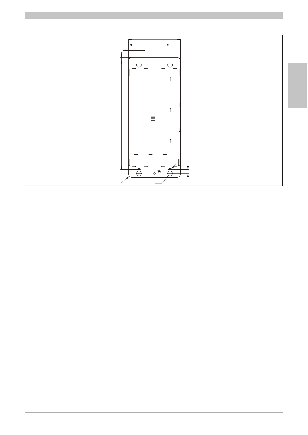
3.1.2.5 Drilling template
R8
244
8
ø5.5
9
ø11
117
23.5
93.5
Technical data • Individual components
Chapter 2
Technical data
Figure 29: 5PC910.SX02-00 - Drilling template
Automation PC 910 user's manual V1.51 91
Page 92
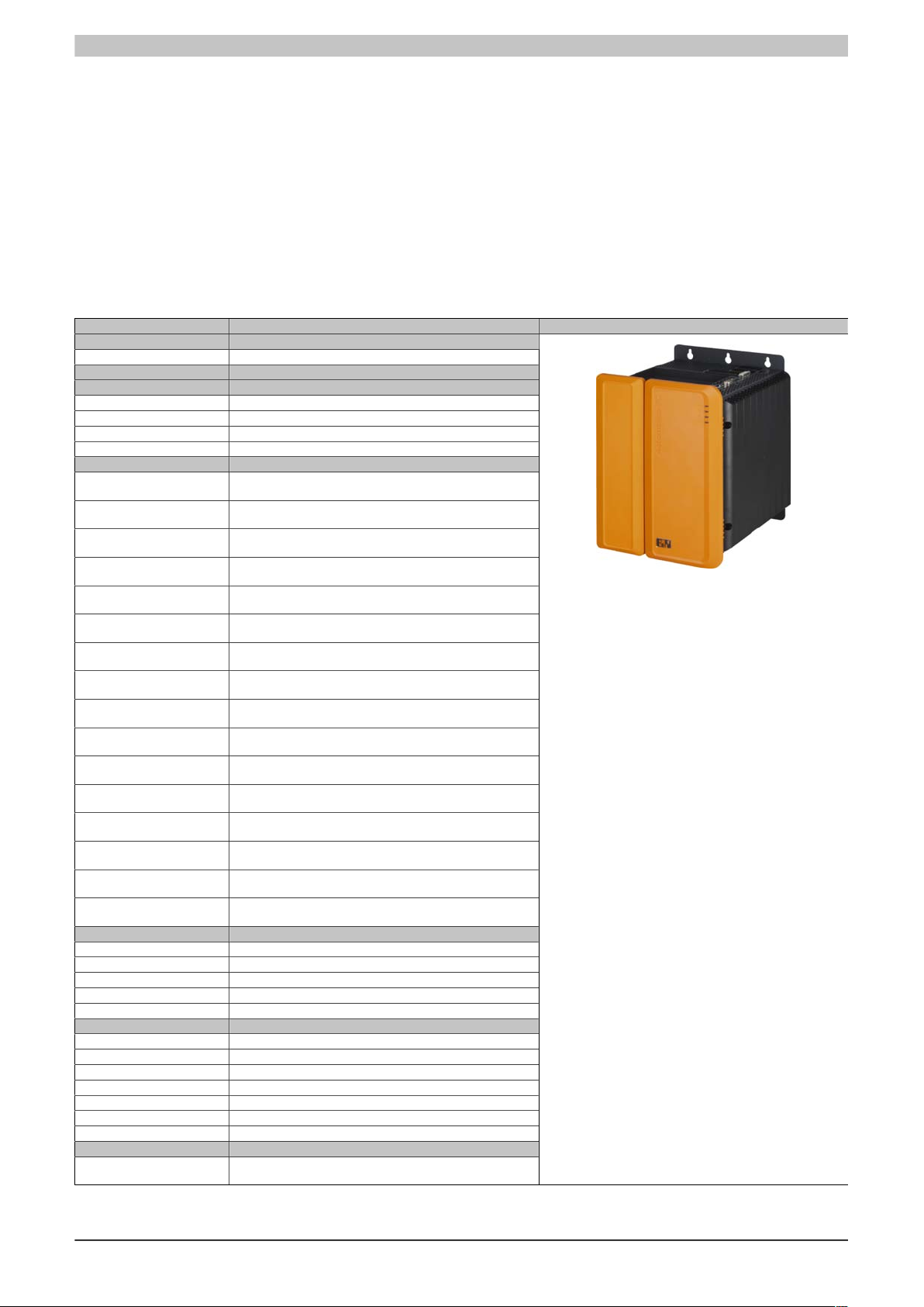
Technical data • Individual components
3.1.3 5PC910.SX05-00
3.1.3.1 General information
•
Slot for a bus unit with 5 PCI/PCIe slots
•
Insert for 1 slide-in compact drive and 2 slide-in drives
•
Insert for 2 interface options
•
SDL/DVI/Monitor and DisplayPort interfaces
•
Insert for monitor/panel option
•
CFast slot
3.1.3.2 Order data
Model number Short description Figure
5PC910.SX05-00 5-slot APC910 system unit
5AC901.BX05-00 APC910 5-slot bus - 5 PCI
5AC901.BX05-01 APC910 5-slot bus - 4 PCI - 1 PCI Express x8
5AC901.BX05-02 APC910 5-slot bus - 2 PCI - 1 PCI Express x8 - 2 PCI Express x1
5AC901.BX05-03 APC910 5-slot bus - 2 PCI Express x4 - 3 PCI Express x1
5PC900.TS17-00 CPU board Intel Core i5 6440EQ - Quad core - Chipset QM170
5PC900.TS17-01 CPU board Intel Core i3 6100E - Dual core - Chipset HM170 -
5PC900.TS17-02 CPU board Intel Celeron G3900E - Dual core - Chipset HM170
5PC900.TS17-03 CPU Board Intel Xeon E3-1515MV5 - Quad core - Chipset
5PC900.TS17-04 CPU board Intel Core i7 6820EQ - Quad core - Chipset QM170
5PC900.TS77-00 CPU board Intel Core i7 3615QE 2.3 GHz - Quad core - Chipset
5PC900.TS77-01 CPU board Intel Core i7 3612QE 2.1 GHz - Quad core - Chipset
5PC900.TS77-02 CPU board Intel Core i7 3555LE 2.5 GHz - Dual core - Chipset
5PC900.TS77-03 CPU board Intel Core i7 3517UE 1.7 GHz - Dual core - Chipset
5PC900.TS77-04 CPU board Intel Core i5 3610ME 2.7 GHz - Dual core - Chipset
5PC900.TS77-05 CPU board Intel Core i3 3120ME 2.4 GHz - Dual core - Chipset
5PC900.TS77-06 CPU board Intel Core i3 3217UE 1.6 GHz - Dual core - Chipset
5PC900.TS77-07 CPU board Intel Celeron 847E 1.1 GHz - Dual core - HM76
5PC900.TS77-08 CPU board Intel Celeron 827E 1.4 GHz - Single core - HM76
5PC900.TS77-09 CPU board Intel Celeron 1020E 2.2 GHz - Dual core - HM76
5PC900.TS77-10 CPU board Intel Celeron 1047UE 1.4 GHz - Dual core - HM76
5AC901.HS00-00 APC910 heat sink, active
5AC901.HS00-01 APC910 active heat sink QM170/HM170
5AC901.HS00-02 APC910 active heat sink CM236
5AC901.HS01-00 APC910 heat sink, passive
5AC901.HS01-01 APC910 passive heat sink QM170/HM170
5MMDDR.016G-04 SO-DIMM DDR4, 16384 MB
5MMDDR.1024-03 SO-DIMM DDR3, 1024 MB
5MMDDR.2048-03 SO-DIMM DDR3, 2048 MB
5MMDDR.4096-03 SO-DIMM DDR3, 4096 MB
5MMDDR.4096-04 SO-DIMM DDR4, 4096 MB
5MMDDR.8192-03 SO-DIMM DDR3, 8192 MB
5MMDDR.8192-04 SO-DIMM DDR4, 8192 MB
0TB103.9 Connector 24 VDC - 3-pin female - Screw clamp terminal block
System units
Required accessories
Bus units
CPU boards
- 2.7 GHz active - For APC910
2.7 GHz active, 1.9 GHz passive - For APC910
- 2.4 GHz active, 1.7 GHz passive - For APC910
CM236 - 2.8 GHz active - For APC910
- 2.8 GHz active - For APC910
QM77 - For APC910
QM77 - For APC910
QM77 - For APC910
QM77 - For APC910
QM77 - For APC910
QM77 - For APC910
QM77 - For APC910
chipset - For APC910
chipset - For APC910
chipset - For APC910
chipset - For APC910
Heat sink
Main memory
Terminal blocks
3.31 mm²
Table 50: 5PC910.SX05-00 - Order data
92 Automation PC 910 user's manual V1.51
Page 93
Technical data • Individual components
Model number Short description Figure
0TB103.91 Connector 24 VDC - 3-pin female - Cage clamp terminal block
3.31 mm²
Optional accessories
Drives
5AC901.CCFA-00 CFast adapter - For slide-in compact slot
5AC901.CHDD-01 500 GB hard disk - Slide-in compact - SATA
5AC901.CSSD-04 128 GB SSD MLC - Slide-in compact - SATA
5AC901.CSSD-05 256 GB SSD MLC - Slide-in compact - Toshiba - SATA
5AC901.CSSD-06 512 GB SSD MLC - Slide-in compact - Toshiba - SATA
5AC901.SDVW-00 DVD drive - DVD-R/RW|DVD+R/RW - Slide-in
5AC901.SSCA-00 Slide-in compact adapter - For slide-in compact drives
Fan kit
5AC901.FA05-00 APC910 fan kit - For 5PC910.SX05-00 system unit
Front cover
5AC901.FF05-00 Front cover for 5-slot APC910 - Orange
5AC901.FF05-01 Front cover for 5-slot APC910 - Dark gray
5AC901.FF05-02 Front cover for 5-slot APC910 - Dark gray - Without logo
5AC901.FF05-03 Front cover for 5-slot APC910 - Orange - Without logo
Interface options
5AC901.I485-00 Interface card - 1x RS232/422/485 interface - For APC910/
PPC900/APC3100/PPC3100
5AC901.ICAN-00 Interface card - 1x CAN interface - For APC910/PPC900/
APC3100/PPC3100
5AC901.ICAN-01 Interface card - 1x CAN interface (SJA1000) - For APC910/
PPC900/APC3100/PPC3100
5AC901.IETH-00 Interface card - 1x ETH 10/100/1000 - For APC910/PPC900/
APC3100/PPC3100
5AC901.IHDA-00 Interface card - 1x audio interface (1x MIC / 1x Line In / 1x OUT)
- For APC910/PPC900/APC3100/PPC3100
5AC901.IPLK-00 Interface card - 1x POWERLINK interface - 2 MB SRAM - For
APC910/PPC900/APC3100/PPC3100
5AC901.IRDY-00 Interface card - Ready relay - For APC910/PPC900/APC3100/
PPC3100
5AC901.ISIO-00 Interface card - System I/O - For APC910/PPC900/APC3100/
PPC3100
5AC901.ISRM-00 Interface card - 2 MB RAM - For APC910/PPC900/APC3100/
PPC3100
Monitor/Panel options
5AC901.LDPO-00 DisplayPort transmitter
5AC901.LSD3-00 SDL3 transmitter
5AC901.LSD4-00 SDL4 transmitter
5AC901.LSDL-00 SDL/DVI transmitter
Uninterruptible power supplies
5AC901.IUPS-00 UPS - For 4.5 Ah battery
5AC901.IUPS-01 UPS - For 2.2 Ah battery
Table 50: 5PC910.SX05-00 - Order data
Chapter 2
Technical data
3.1.3.3 Technical data
Information:
The following specifications, properties and limit values apply only to this individual component and
may deviate from those that apply to the complete system. For the complete system in which this
individual component is used, for example, the data specified for that complete system applies.
Model number 5PC910.SX05-00
General information
Cooling Passive via heat sink and optionally supported with an active fan kit
LED status indicators Power, HDD, Link, Run
B&R ID code 0xD844
Battery
Type Renata 950 mAh
Service life 4 years
Removable Yes, accessible behind the front cover
Design Lithium ion
Power button Yes
Reset button Yes
Buzzer Yes
Table 51: 5PC910.SX05-00 - Technical data
Automation PC 910 user's manual V1.51 93
1)
Page 94
Technical data • Individual components
Model number 5PC910.SX05-00
Certifications
CE Yes
UL cULus E115267
GOST-R Yes
Controller
Boot loader BIOS
Real-time clock
Battery-backed Yes
Power failure logic
Controller MTCX
Buffer time 10 ms
Memory
Type Depends on the CPU board being used
Memory size Depends on the CPU board being used
Graphics
Controller Depends on the CPU board being used
Interfaces
COM1
Type RS232, modem-capable, not electrically isolated
Design 9-pin, male, DSUB connector
UART 16550-compatible, 16-byte FIFO
Max. baud rate 115 kbit/s
CFast slot
Quantity 1
Type SATA III (SATA 60 Gbit/s)
USB
Quantity 5
Type 4x USB 3.0 (top)
Design Type A
Transfer rate Low speed (1.5 Mbit/s), full speed (12 Mbit/s), high speed (480 Mbit/s), SuperSpeed (5 Gbit/s)
Current-carrying capacity Max. 1 A per connection
Ethernet
Quantity 2
Design Shielded RJ45
Transfer rate 10/100/1000 Mbit/s
Max. baud rate 1 Gbit/s
DisplayPort
Quantity 1
Version Depends on the CPU board being used
Panel/Monitor interface
Design DVI-I
Type SDL/DVI/Monitor
Inserts
PCI/PCIe slots
Quantity 5 PCI slots or
Slide-in drives
Quantity 2
Type Depends on the CPU board being used
Slide-in compact drives
Quantity 1
Type SATA III (SATA 60 Gbit/s)
Interface option 2
Monitor/Panel option 1
Add-on UPS slot Yes
Insert for fan kit Yes
Electrical characteristics
Nominal voltage 24 VDC ±25%, SELV
Nominal current Max. 5.5 A
Inrush current Max. 60 A for <300 μs
Overvoltage category per EN 61131-2 II
Electrical isolation Yes
Operating conditions
Pollution degree per EN 61131-2 Pollution degree 2
Degree of protection per EN 60529 IP20
Table 51: 5PC910.SX05-00 - Technical data
Industrial control equipment
2)
1x USB 2.0 (front)
4 PCI slots and 1 PCIe slot or
2 PCI slots and 3 PCIe slots or
5 PCIe slots
4)
5)
6)
7)
8)
3)
94 Automation PC 910 user's manual V1.51
Page 95
Technical data • Individual components
Model number 5PC910.SX05-00
Environmental conditions
Temperature
Operation Component-dependent
Storage -20 to 60°C
Transport -20 to 60°C
Relative humidity
Operation Component-dependent
Storage Component-dependent
Transport Component-dependent
10)
Vibration
Operation (continuous) 2 to 9 Hz: 1.75 mm amplitude / 9 to 200 Hz: 0.5 g
Operation (occasional) 2 to 9 Hz: 3.5 mm amplitude / 9 to 200 Hz: 1 g
Storage 2 to 8 Hz: 7.5 mm amplitude / 8 to 200 Hz: 2 g / 200 to 500 Hz: 4 g
Transport 2 to 8 Hz: 7.5 mm amplitude / 8 to 200 Hz: 2 g / 200 to 500 Hz: 4 g
10)
Shock
Operation 15 g, 11 ms
Storage 30 g, 6 ms
Transport 30 g, 6 ms
Elevation
Operation -300 to 3000 m above sea level
Mechanical characteristics
12)
Housing
Material Galvanized plate, plastic
Coating Anthracite gray
Dimensions
Width 211 mm
Height 270 mm
Depth 254.75 mm
Weight 2850 g
Table 51: 5PC910.SX05-00 - Technical data
1) At 50°C, 8.5 µA of the supplied components and a self-discharge of 40%. If an interface option with SRAM or POWERLINK has been installed, the service
life is 2½ years.
2) Maintenance Controller Extended.
3) The SuperSpeed transfer rate (5 Gbit/s) is only possible with USB 3.0.
4) The PCI and PCIe slots available depend on the bus unit being used (5AC901.BX05-00, 5AC901.BX05-01, 5AC901.BX05-02 or 5AC901.BX05-03).
5) This UPS module can only be operated in the IF option 1 slot.
6) EN 60950 requirements must be observed; see section "+24 VDC power supply" in the user's manual.
7) Maximum current consumption (24 V / 130 W). This can vary depending on the configuration (see "Power calculation" section). The inrush current must also
be taken into consideration when selecting the power supply.
8) Only when all interface covers and the front cover are closed.
9) Detailed information can be found in the temperature tables in the user's manual.
10) Maximum values unless specified otherwise by another individual component. Vibration testing is performed in accordance with EN 60068-2-6. Shock testing
is performed in accordance with EN 60068-2-27.
11) The maximum ambient temperature is typically derated by 1°C per 1000 meters (starting at 500 meters above sea level).
12) There may be visible deviations in the color and surface appearance depending on the process or batch.
9)
11)
Chapter 2
Technical data
Automation PC 910 user's manual V1.51 95
Page 96
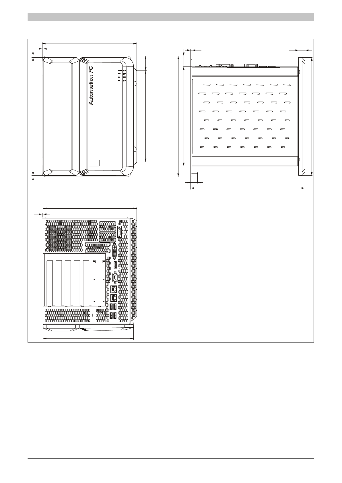
Technical data • Individual components
1.95
3
3
211
33
204
209
2
202
254.75
264
14
15
2.5
270
222
24
3.1.3.4 Dimensions
Figure 30: 5PC910.SX05-00 - Dimensions
96 Automation PC 910 user's manual V1.51
Page 97
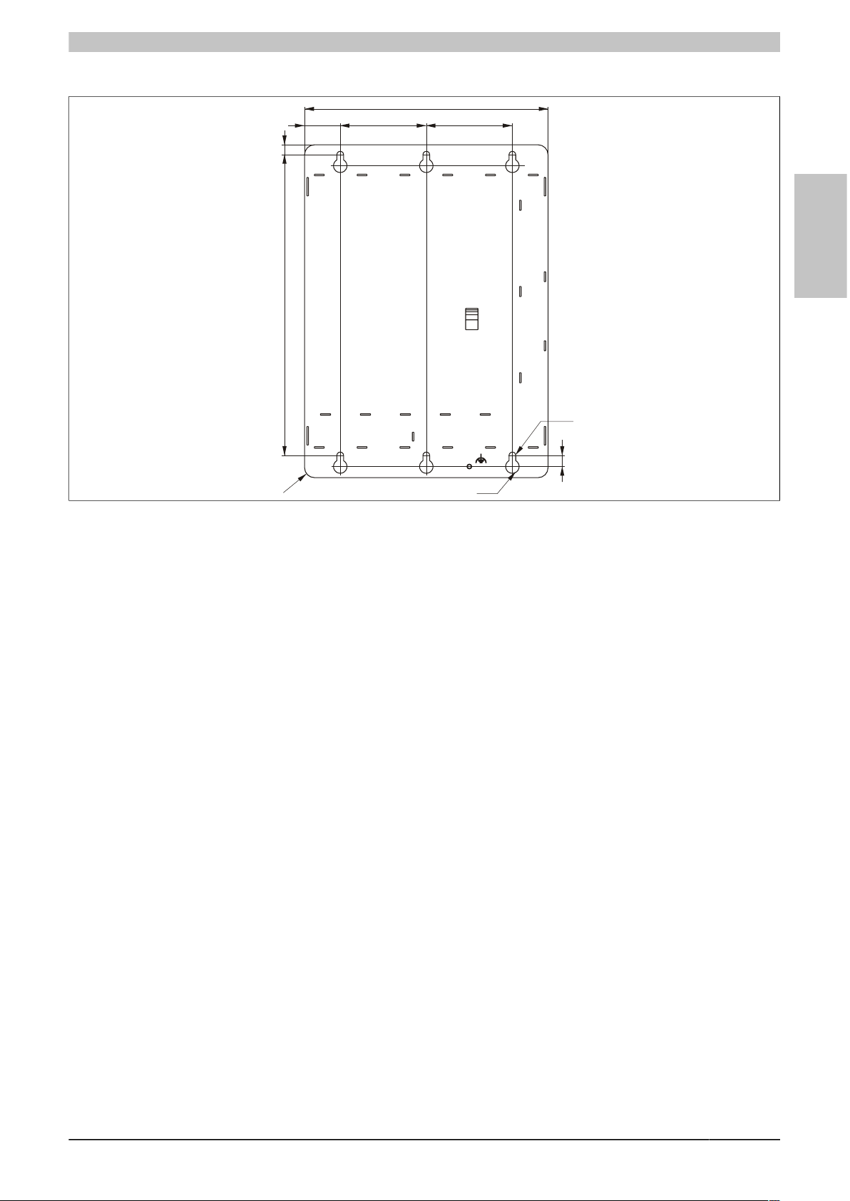
3.1.3.5 Drilling template
ø5.5
9
ø11
198
29 70 70
R8
244 8
Technical data • Individual components
Chapter 2
Technical data
Figure 31: 5PC910.SX05-00 - Drilling template
Automation PC 910 user's manual V1.51 97
Page 98
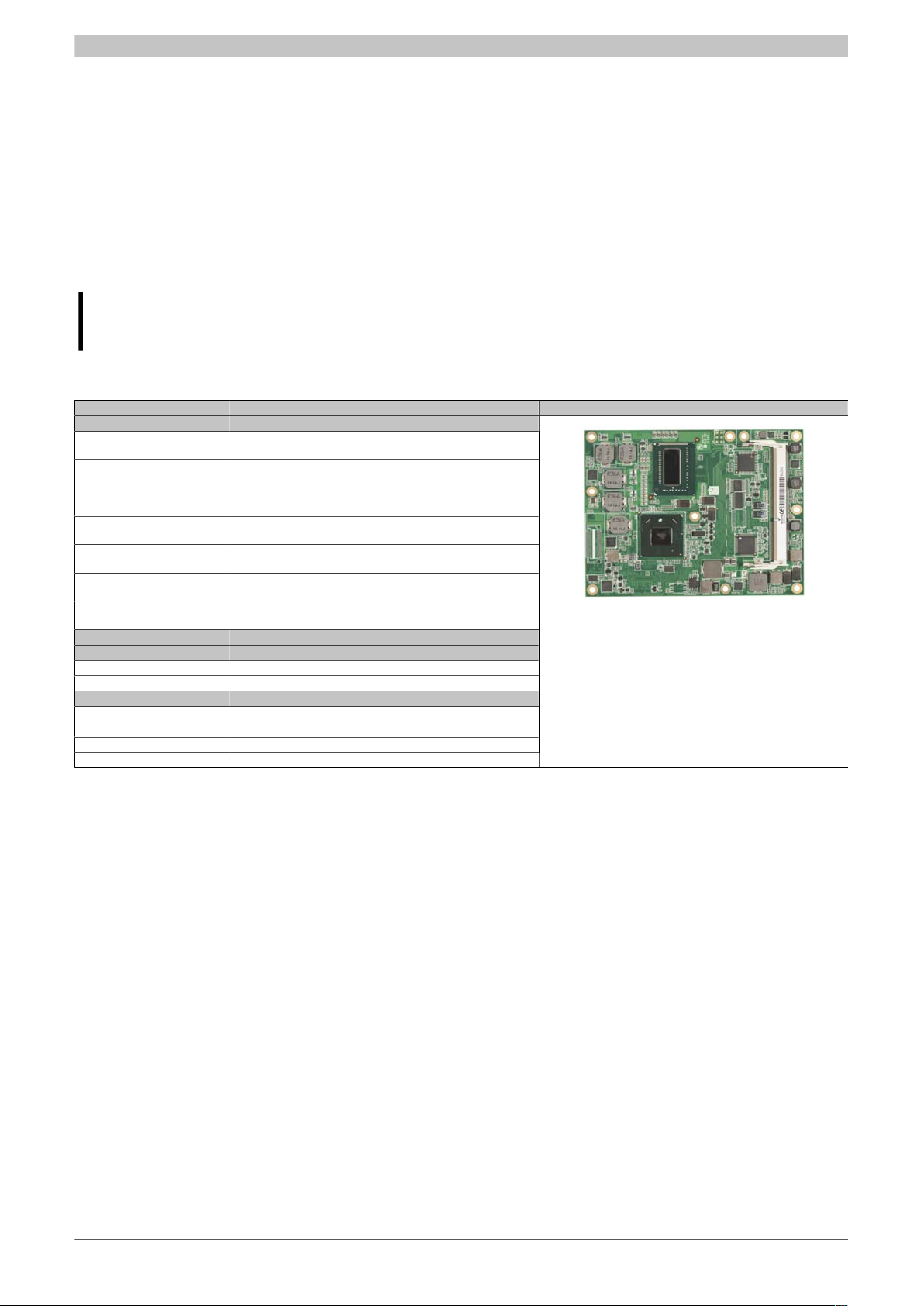
Technical data • Individual components
3.2 QM77 CPU boards
3.2.1 5PC900.TS77-0x
3.2.1.1 General information
•
Intel Core i-series processors
•
Intel QM77 chipset
•
2x DDR3 memory slots
•
Intel HD Graphics 4000
•
AMI BIOS (UEFI)
Information:
A fan kit is required when using the 5PC900.TS77-00 CPU board.
3.2.1.2 Order data
Model number Short description Figure
5PC900.TS77-00 CPU board Intel Core i7 3615QE 2.3 GHz - Quad core - QM77
5PC900.TS77-01 CPU board Intel Core i7 3612QE 2.1 GHz - Quad core - QM77
5PC900.TS77-02 CPU board Intel Core i7 3555LE 2.5 GHz - Dual core - QM77
5PC900.TS77-03 CPU board Intel Core i7 3517UE 1.7 GHz - Dual core - QM77
5PC900.TS77-04 CPU board Intel Core i5 3610ME 2.7 GHz - Dual core - QM77
5PC900.TS77-05 CPU board Intel Core i3 3120ME 2.4 GHz - Dual core - QM77
5PC900.TS77-06 CPU board Intel Core i3 3217UE 1.6 GHz - Dual core - QM77
5AC901.HS00-00 APC910 heat sink, active
5AC901.HS01-00 APC910 heat sink, passive
5MMDDR.1024-03 SO-DIMM DDR3, 1024 MB
5MMDDR.2048-03 SO-DIMM DDR3, 2048 MB
5MMDDR.4096-03 SO-DIMM DDR3, 4096 MB
5MMDDR.8192-03 SO-DIMM DDR3, 8192 MB
CPU boards
chipset - For APC910
chipset - For APC910
chipset - For APC910
chipset - For APC910
chipset - For APC910
chipset - For APC910
chipset - For APC910
Required accessories
Heat sink
Main memory
Table 52: 5PC900.TS77-00, 5PC900.TS77-01, 5PC900.TS77-02, 5PC900.TS77-03,
5PC900.TS77-04, 5PC900.TS77-05, 5PC900.TS77-06 - Order data
98 Automation PC 910 user's manual V1.51
Page 99
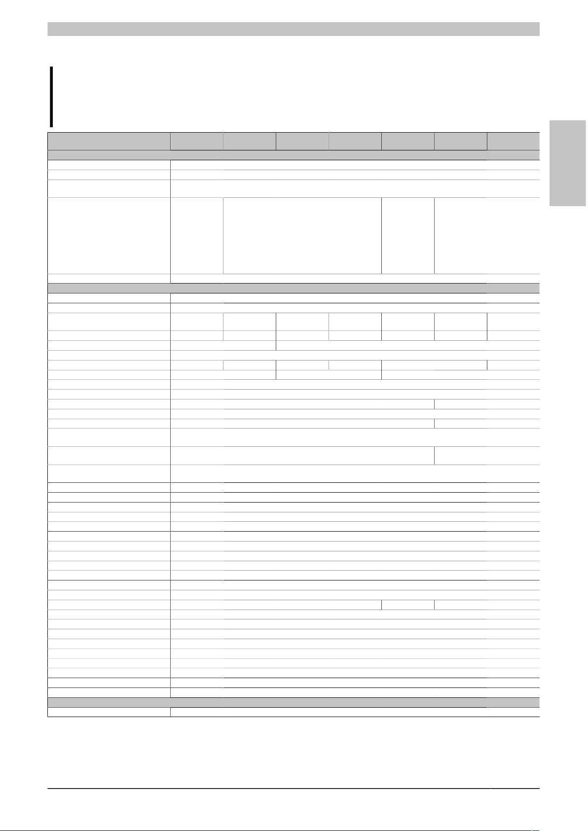
Technical data • Individual components
3.2.1.3 Technical data
Information:
The following specifications, properties and limit values apply only to this individual component and
may deviate from those that apply to the complete system. For the complete system in which this
individual component is used, for example, the data specified for that complete system applies.
Model number 5PC900.
TS77-00
General information
Certifications
CE Yes
UL cULus E115267
DNV GL Temperature:
B (0 - 55°C)
Humidity:
B (up to 100%)
Vibration:
A (0.7 g)
EMC: B
(Bridge and
open deck)
GOST-R Yes
Controller
Boot loader Embedded AMI BIOS
Processor
Type Intel Core
i7-3615QE
Clock frequency 2300 MHz 2100 MHz 2500 MHz 1700 MHz 2700 MHz 2400 MHz 1600 MHz
Number of cores 4 2
Architecture 22 nm
Thermal design power (TDP) 45 W 35 W 25 W 17 W 35 W 17 W
Intel Smart Cache 6 MB 4 MB 3 MB
External bus DMI, 5 GT/s
Intel 64 architecture Yes
Intel Turbo Boost Technology 2.0 No
Intel Hyper-Threading Technology Yes
Intel vPro Technology Yes No
Intel Virtualization Technology (VT-
x)
Intel Virtualization Technology for
Directed I/O (VT-d)
Enhanced Intel SpeedStep Tech-
nology
Chipset Intel QM77
Trusted Platform Module No
Real-time clock
Precision At 25°C: typ. 12 ppm (1 second) per day
Battery-backed Yes
Memory slot
Number of memory channels 2
Type DDR3
Memory size Max. 16 GB
Max. memory bandwidth 25.6 GB/s
Graphics
Controller Intel HD Graphics 4000
Max. dynamic graphics frequency 1 GHz 950 MHz 900 MHz
Color depth Max. 32-bit
DirectX support 11
OpenGL support 4.0
Resolution
DVI Resolution up to 1920 x 1200 (WUXGA)
RGB 350 MHz RAMDAC, resolution up to 2048 x 1536 @ 75 Hz (QXGA)
DisplayPort Version 1.1
Mass memory management 4x SATA
Power management ACPI 4.0 with battery support
Operating conditions
Pollution degree per EN 61131-2 Pollution degree 2
1)
5PC900.
TS77-01
Intel Core
i7-3612QE
5PC900.
TS77-02
- Temperature:
Intel Core
i7-3555LE
Yes No
5PC900.
TS77-03
Industrial control equipment
B (0 - 55°C)
B (up to 100%)
(Bridge and
open deck)
Intel Core
i7-3517UE
Yes
Yes
5PC900.
TS77-04
Humidity:
Vibration:
A (0.7 g)
EMC: B
Intel Core
i5-3610ME
2)
5PC900.
TS77-05
1)
Intel Core
i3-3120ME
5PC900.
TS77-06
-
Intel Core
i3-3217UE
Table 53: 5PC900.TS77-00, 5PC900.TS77-01, 5PC900.TS77-02, 5PC900.TS77-03,
5PC900.TS77-04, 5PC900.TS77-05, 5PC900.TS77-06 - Technical data
1) Yes, although applies only if all components installed in the complete system have this certification and are listed on the associated DNV GL certificate for
the product family.
2) At max. specified ambient temperature: typ. 58 ppm (5 seconds) - worst-case 220 ppm (19 seconds).
Chapter 2
Technical data
Automation PC 910 user's manual V1.51 99
Page 100
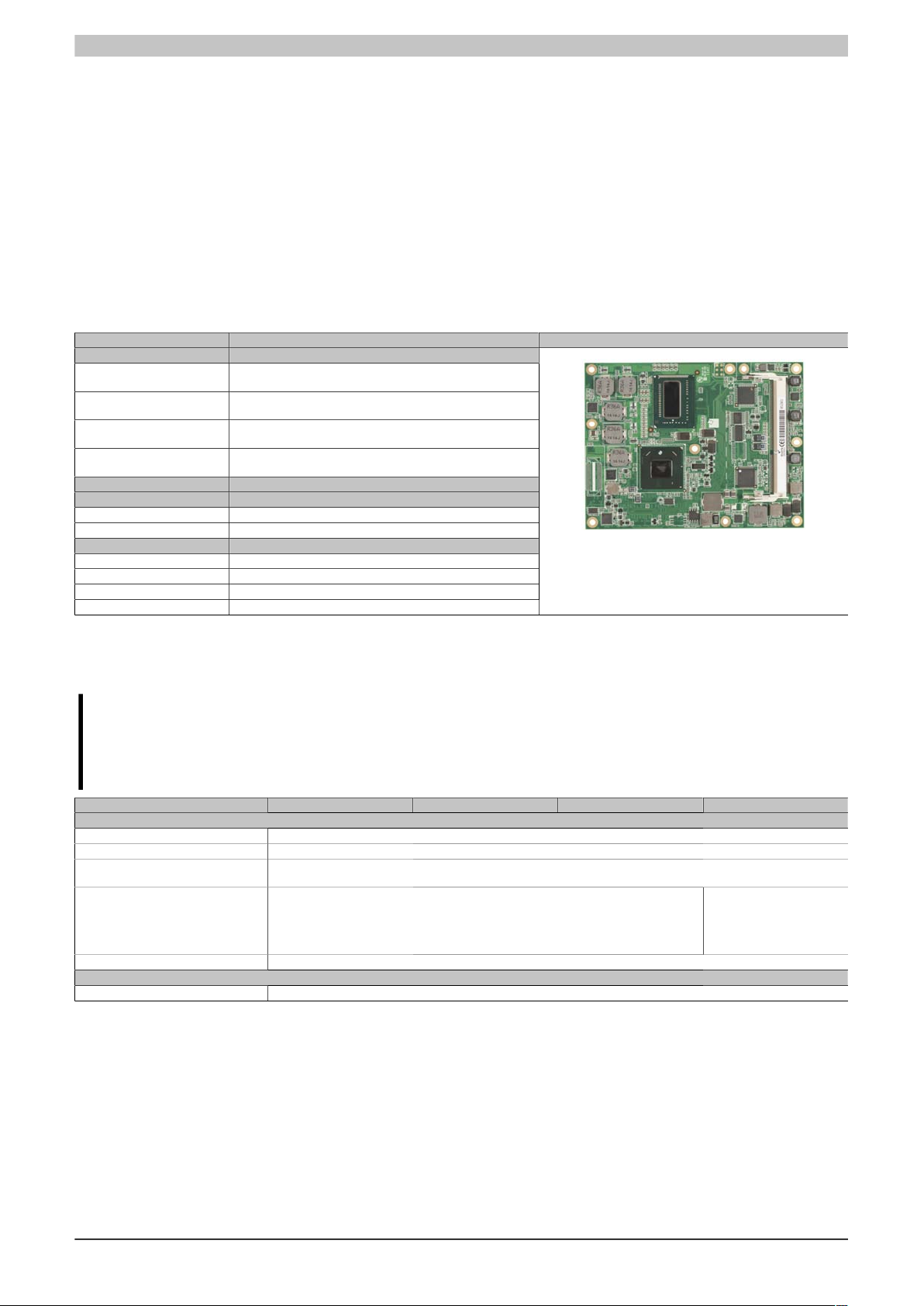
Technical data • Individual components
3.3 HM76 CPU boards
3.3.1 5PC900.TS77-0x
3.3.1.1 General information
•
Intel Celeron processors
•
Intel HM76 chipset
•
2x DDR3 memory slots
•
Intel HD Graphics 2000/2500
•
AMI BIOS (UEFI)
3.3.1.2 Order data
Model number Short description Figure
5PC900.TS77-07 CPU board Intel Celeron 847E 1.1 GHz - Dual core - HM76
5PC900.TS77-08 CPU board Intel Celeron 827E 1.4 GHz - Single core - HM76
5PC900.TS77-09 CPU board Intel Celeron 1020E 2.2 GHz - Dual core - HM76
5PC900.TS77-10 CPU board Intel Celeron 1047UE 1.4 GHz - Dual core - HM76
5AC901.HS00-00 APC910 heat sink, active
5AC901.HS01-00 APC910 heat sink, passive
5MMDDR.1024-03 SO-DIMM DDR3, 1024 MB
5MMDDR.2048-03 SO-DIMM DDR3, 2048 MB
5MMDDR.4096-03 SO-DIMM DDR3, 4096 MB
5MMDDR.8192-03 SO-DIMM DDR3, 8192 MB
CPU boards
chipset - For APC910
chipset - For APC910
chipset - For APC910
chipset - For APC910
Required accessories
Heat sink
Main memory
Table 54: 5PC900.TS77-07, 5PC900.TS77-08, 5PC900.TS77-09, 5PC900.TS77-10 - Order data
3.3.1.3 Technical data
Information:
The following specifications, properties and limit values apply only to this individual component and
may deviate from those that apply to the complete system. For the complete system in which this
individual component is used, for example, the data specified for that complete system applies.
Model number 5PC900.TS77-07 5PC900.TS77-08 5PC900.TS77-09 5PC900.TS77-10
General information
Certifications
CE Yes
UL cULus E115267
DNV GL - Temperature: B (0 - 55°C)
GOST-R Yes
Controller
Boot loader Embedded AMI BIOS
Industrial control equipment
Humidity: B (up to 100%)
Vibration: A (0.7 g)
EMC: B (Bridge
and open deck)
1)
Table 55: 5PC900.TS77-07, 5PC900.TS77-08, 5PC900.TS77-09, 5PC900.TS77-10 - Technical data
100 Automation PC 910 user's manual V1.51
 Loading...