

B&R 8BVI0014HWD0.000-1 Datasheet
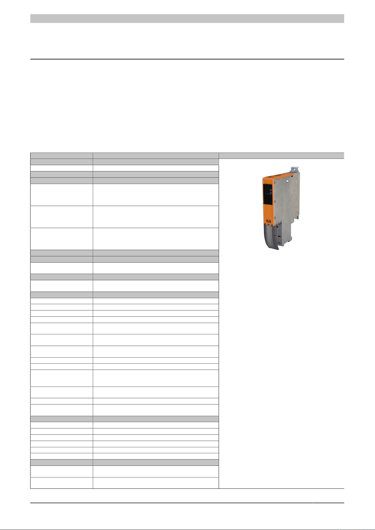
8BVI0014HWD0.000-1
1 General information
•
Uncontrolled and safe stops integrated
•
Integrated connection for motor holding brake and temperature sensor
•
2 slots for ACOPOSmulti plug-in modules
•
2-axis modules contain two complete standalone inverters in one inverter module
2 Order data
8BVI0014HWD0.000-1
Model number Short description Figure
8BVI0014HWD0.000-1 ACOPOSmulti inverter module 1.9 A, HV, wall mounting, 2 axes
8BZVI0055D0.000-1A Screw clamp set for ACOPOSmulti 8BVI00xxHxD0 modules: 1x
8BZVI0055D0.500-1A 50x Screw clamp terminal block set for ACOPOS-
8BZVI0055D0.A00-1A 100x Screw clamp terminal block set for ACOPOS-
8BXB000.0000-00 ACPmulti accessory set for encoder buffering consisting of: 1
8BXF001.0000-00 ACOPOSmulti fan module, replacement fan for ACOPOSmulti
8BAC0120.000-1 ACOPOSmulti plug-in module, EnDat 2.1 interface
8BAC0120.001-2 ACOPOSmulti plug-in module, EnDat 2.2 interface
8BAC0121.000-1 ACOPOSmulti plug-in module, HIPERFACE interface
8BAC0122.000-1 ACOPOSmulti plug-in module, resolver interface 10 kHz
8BAC0123.000-1 ACOPOSmulti plug-in module, incremental encoder and SSI ab-
8BAC0123.001-1 ACOPOSmulti plug-in module, incremental encoder interface for
8BAC0123.002-1 ACOPOSmulti plug-in module, incremental encoder interface for
8BAC0124.000-1 ACOPOSmulti plug-in module, SinCos interface
8BAC0125.000-1 ACOPOSmulti plug-in module, SinCos EnDat 2.1/SSI interface
8BAC0130.000-1 ACOPOSmulti plug-in module, 2 digital outputs, 50 mA, max.
8BAC0130.001-1 ACOPOSmulti plug-in module, 2 digital outputs, 50 mA, max.
8BAC0132.000-1 ACOPOSmulti plug-in module, 4 analog inputs ±10 V
8BAC0133.000-1 ACOPOSmulti plug-in module, 3 RS422 outputs for ABR en-
X20CA0E61.00020 POWERLINK connection cable, RJ45 to RJ45, 0.2 m
X20CA0E61.00025 POWERLINK connection cable, RJ45 to RJ45, 025 m
X20CA0E61.00030 POWERLINK connection cable, RJ45 to RJ45, 03 m
X20CA0E61.00035 POWERLINK connection cable, RJ45 to RJ45, 035 m
X20CA0E61.00050 POWERLINK connection cable, RJ45 to RJ45, 0.5 m
X20CA0E61.00100 POWERLINK connection cable, RJ45 to RJ45, 1 m
8SCS000.0000-00 ACOPOSmulti shield component set: 1 shield plate 1x type 0, 1
8SCS002.0000-00 ACOPOSmulti shield component set: 1x clamping plate; 2x
Wall mounting
Required accessories
Terminal block sets
8TB2112.2010-00, 1x 8TB2108.2010-00, 1x 8TB2104.203L-00,
1x 8TB2104.203F-00, 1x 8TB3104.204G-11, 1x
8TB3104.204K-11
multi modules 8BVI00xxHxD0: 1x 8TB2112.2010-00, 1x
8TB2108.2010-00, 1x 8TB2104.203L-00, 1x 8TB2104.203F-00,
1x 8TB3104.204G-11, 1x 8TB3104.204K-11
multi modules 8BVI00xxHxD0: 1x 8TB2112.2010-00, 1x
8TB2108.2010-00, 1x 8TB2104.203L-00, 1x 8TB2104.203F-00,
1x 8TB3104.204G-11, 1x 8TB3104.204K-11
Optional accessories
Accessory sets
lithium battery AA 3.6 V; 1 protective cap for battery holder
Fan modules
modules (8BxP / 8B0C / 8BVI / 8BVE / 8B0K)
Plug-in modules
solute encoder interface for RS422 signals
5 V single-ended and 5 V differential signals
24 V single-ended and 24 V differential signals
62.5 kHz, 2 digital outputs, 500 mA, max. 1.25 kHz, 2 digital
inputs 24 VDC
62.5 kHz, 4 digital outputs, 500 mA, max. 1.25 kHz
coder emulation, 1 Mhz
POWERLINK cable
Shield component sets
hose clamp, B 9 mm, D 12-22 mm
clamps D 4-13.5 mm; 4x screws
Table 1: 8BVI0014HWD0.000-1 - Order data
Data sheet V 1.4 1
8BVI0014HWD0.000-1
Model number Short description Figure
8SCS005.0000-00 ACOPOSmulti shield component set: 1x slot cover/shield plate
8SCS009.0000-00 ACOPOSmulti shield component set: 1x ACOPOSmulti holding
plate SK8-14; 1x shield terminal SK14
Terminal blocks
8TB2104.203F-00 4-pin screw clamp, single row, spacing: 5.08 mm, label 3: T- T
+ B- B+, F keying: 0101
8TB2104.203L-00 4-pin screw clamp, single row, spacing: 5.08 mm, label 3: T- T
+ B- B+, L keying: 1010
8TB2108.2010-00 8-pin screw clamp, single row, spacing: 5.08 mm, label 1: num-
bered serially
8TB2112.2010-00 12-pin screw clamp, single row, spacing: 5.08 mm, label 1: num-
bered serially
8TB3104.204G-11 4-pin screw clamp, single row, spacing: 7.62 mm, label 4: PE W
V U, G keying: 0110
8TB3104.204K-11 4-pin screw clamp, single row, spacing: 7.62 mm, label 4: PE W
V U, K keying: 1001
Undefined
8SCSE01.0100-00 ACOPOS P3 Schirmkomponentenset: 1x Schirmblech 4fach
Typ 1; 1x Schlauchschelle, B 9 mm, D 12-22 mm
8SCSE02.0100-00 ACOPOS P3 Schirmkomponentenset: 1x Klemmbügelblech; 2x
Klemmbügel D 4-13,5 mm; 2x Schrauben
8SCSE02.0200-00 ACOPOS P3 Schirmkomponentenset: 1x Klemmbügelblech; 2x
Klemmbügel D 4-13,5 mm; 2x Schrauben
Table 1: 8BVI0014HWD0.000-1 - Order data
3 Technical data
Model number 8BVI0014HWD0.000-1
General information
B&R ID code 0x26DF
Cooling and mounting method Wall mounting
Slots for plug-in modules 2
Certification
CE Yes
KC Yes
UL cULus E225616
Functional Safety
1)
Power Conversion Equipment
Yes
DC bus connection
Voltage
Nominal 750 VDC
Continuous power consumption
Power loss depending on switching frequency
2)
3)
2.91 kW
Switching frequency 5 kHz [1.2 * IM² + 2.62 * IM + 100] W
Switching frequency 10 kHz [2.56 * IM² + 2.8 * IM + 200] W
Switching frequency 20 kHz [6 * IM² - 9.4 * IM + 430] W
DC bus capacitance 165 µF
Design ACOPOSmulti backplane
24 VDC supply
Input voltage 25 VDC ±1.6%
Input capacitance 23.5 µF
Max. power consumption 16 W + P
SLOT1
+ P
SLOT2
+ P
24 V Out
+ P
HoldingBrake(s)
Design ACOPOSmulti backplane
24 VDC output
Quantity 2
Output voltage
DC bus voltage (UDC): 260 to 315 VDC 25 VDC * (UDC/ 315)
DC bus voltage (UDC): 315 to 800 VDC 24 VDC ±6%
Protection 250 mA (slow-blow) electronic, automatic reset
Motor connection
Quantity 2
Continuous power per motor connection
Continuous current per motor connection
Reduction of continuous current depending on
switching frequency
5)
Switching frequency 5 kHz No reduction
Switching frequency 10 kHz No reduction
Switching frequency 20 kHz 0.11 A/K (from 15°C)
2)
2)
1.4 kW
1.9 A
eff
6)
7)
Reduction of continuous current depending on the
installation elevation
Starting at 500 m above sea level 0.19 A
Peak current per motor connection 4.7 A
per 1000 m
eff
eff
Table 2: 8BVI0014HWD0.000-1 - Technical data
4)
2 Data sheet V 1.4

Model number 8BVI0014HWD0.000-1
Nominal switching frequency 5 kHz
Possible switching frequencies
Electrical stress of the connected motor in accor-
dance with IEC TS 60034-25
8)
9)
5 / 10 / 20 kHz
Limit value curve A
Protective measures
Overload protection Yes
Short circuit and ground fault protection Yes
Max. output frequency 598 Hz
10)
Design
U, V, W, PE Male connector
Shield connection Yes
Terminal connection cross section
Flexible and fine wire lines
With wire end sleeves 0.25 to 6 mm²
Approbation data
UL/C-UL-US 30 to 10
CSA 28 to 10
Terminal cable cross section dimension of shield
12 to 22 mm
connection
Max. motor line length depending on switching fre-
quency
Switching frequency 5 kHz 25 m
Switching frequency 10 kHz 25 m
Switching frequency 20 kHz 10 m
Motor holding brake connection
Quantity 2
Output voltage
11)
24 VDC +5.8% / -0%
Continuous current 1.1 A
Max. internal resistance 0.5 Ω
Extinction potential Approx. 30 V
Max. extinction energy per switching operation 1.5 Ws
Max. switching frequency 0.5 Hz
Protective measures
Overload and short circuit protection Yes
Open circuit monitoring Yes
Undervoltage monitoring Yes
Response threshold for open circuit monitoring Approx. 0.25 A
Response threshold for undervoltage monitoring 24 VDC +0% / -4%
Enable inputs
Quantity 4 (2 per axis)
Wiring Sink
Electrical isolation
Input - Inverter module Yes
Input - Input Yes
Input voltage
Nominal 24 VDC
Maximum 30 VDC
Input current at nominal voltage Approx. 30 mA
Switching threshold
Low <5 V
High >15 V
Switching delay at nominal input voltage
Enable 1 -> 0, PWM off Max. 20.5 ms
Enable 0 -> 1, ready for PWM Max. 100 µs
Modulation compared to ground potential Max. ±38 V
OSSD signal connections
13)
permitted
Max. test pulse length: 500 µs
Trigger inputs
Quantity 2
Wiring Sink
Electrical isolation
Input - Inverter module Yes
Input - Input Yes
Input voltage
Nominal 24 VDC
Maximum 30 VDC
Switching threshold
Low <5 V
High >15 V
Input current at nominal voltage Approx. 10 mA
Switching delay
Rising edge 52 µs ±0.5 µs (digitally filtered)
Falling edge 53 µs ±0.5 µs (digitally filtered)
Table 2: 8BVI0014HWD0.000-1 - Technical data
8BVI0014HWD0.000-1
12)
Data sheet V 1.4 3

8BVI0014HWD0.000-1
Model number 8BVI0014HWD0.000-1
Modulation compared to ground potential Max. ±38 V
Electrical characteristics
Discharge capacitance 0.2 µF
Operating conditions
Permitted mounting orientations
Hanging vertically Yes
Lying horizontally Yes
Standing horizontally No
Installation at elevations above sea level
Nominal 0 to 500 m
Maximum
Degree of pollution in accordance with EN
61800-5-1
Overvoltage category in accordance with EN
61800-5-1
EN 60529 protection IP20
Environmental conditions
Temperature
Operation
Storage -25 to 55°C
Transport -25 to 70°C
Relative humidity
Operation 5 to 85%
Storage 5 to 95%
Transport Max. 95% at 40°C
Mechanical characteristics
Dimensions
Width 53 mm
Height 317 mm
Depth
Weight Approx. 2.8 kg
Module width 1
1) Achievable safety classifications (safety integrity level, safety category, performance level) are documented in the user's manual (section "Safety technology").
2) Valid in the following conditions: 750 VDC DC bus voltage, 5 kHz switching frequency, 40°C ambient temperature, installation elevation <500 m above sea
3) IM = 0.5 * (I
4) P
5) Valid in the following conditions: 750 VDC DC bus voltage. The temperature specifications refer to the ambient temperature.
6) Value for the nominal switching frequency.
7) The module cannot supply the full continuous current at this switching frequency. This unusual value for the ambient temperature, at which derating of the
8) B&R recommends operating the module at its nominal switching frequency. Operating the module at a higher switching frequency for application-specific
9) If necessary, the stress of the motor isolation system can be reduced by an additional externally wired dv/dt choke. For example, the RWK 305 three-phase
10) The module's electrical output frequency (SCTRL_SPEED_ACT * MOTOR_POLEPAIRS) is monitored to protect against dual use in accordance with EC
11) During project development, it is necessary to check if the minimum voltage can be maintained on the holding brake with the specified wiring. The operating
12) The specified value is only valid under the following conditions:
13) OSSD (open signal switching device) signals are used to monitor signal lines for short circuits and cross faults.
14) Continuous operation at elevations ranging from 500 m to 4000 m above sea level is possible (taking the specified continuous current reductions into
15) Continuous operation at ambient temperatures ranging from 40°C to max. 55°C is possible (taking the specified continuous current reductions into consid-
16) These dimensions refer to the actual device dimensions including the respective mounting plate. Make sure to leave additional space above and below the
14)
4000 m
2 (non-conductive pollution)
III
Nominal 5 to 40°C
Maximum
15)
16)
55°C
Wall mounting 263 mm
Table 2: 8BVI0014HWD0.000-1 - Technical data
level, no derating due to cooling type.
I
... Current on X5A motor connection [A
X5A
I
... Current on X5B motor connection [A
X5B
SLOT1
P
SLOT2
P
24 V Out
continuous current must be taken into account, ensures that the derating of the continuous current can be determined in the same manner as at other
switching frequencies.
reasons reduces the continuous current and increases the CPU load. When using 2-axis modules, the increased CPU load reduces the functionality of the
drive; if this is not taken into consideration, the computing time can be exceeded in extreme cases.
du/dt choke from Schaffner (www.schaffner.com) can be used. Important: Even when using a dv/dt choke, it is necessary to ensure that an EMC-compatible,
low inductance shield connection is used!
regulation 428/2009 | 3A225. If the electrical output frequency of the module exceeds the limit value of 598 Hz uninterrupted for more than 0.5 s, then the
current movement is aborted and error 6060 is output (Power element: Limit speed exceeded).
voltage range of the holding brake can be found in the user's manual for the respective motor.
- The 24 VDC supply for the module is provided by an 8B0C auxiliary supply module installed on the same mounting plate.
- Connection between S1 and S2 (activation of the external holding brake) using a jumper with a max. length of 10 cm.
If the 24 VDC supply for the module is applied to the mounting plate using an 8BVE expansion module, then the output voltage is reduced because of voltage
drops on the expansion cable. In this case, undervoltage monitoring must be disabled.
If jumpers longer than 10 cm are used to connect S1 and S2, then the output voltage is reduced because of voltage drops on the jumpers.
consideration). Requirements that go above and beyond this must be arranged with B&R.
eration), but this will result in a shorter service life.
devices for mounting, connections and air circulation.
+ I
)
X5A
X5B
... Max. power consumption P
... Max. power consumption P
]
Eff
]
Eff
[W] of the plug-in module in SLOT1 (see the technical data for the respective plug-in module).
8BAC
[W] of the plug-in module in SLOT2 (see the technical data for the respective plug-in module).
8BAC
... Power [W] that is output to the connections X2/+24 V Out 1 and X2/+24 V Out 2 on the module (max. 10 W).
4 Data sheet V 1.4
8BVI0014HWD0.000-1
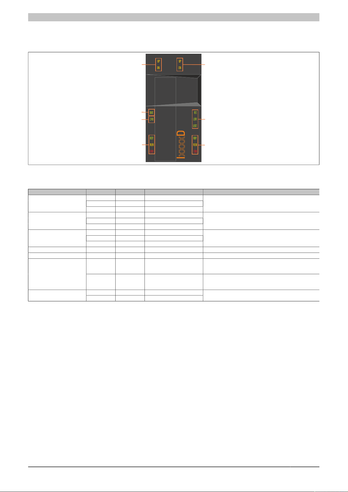
Encoder SLOT1
Status of backup battery
Power supply
POWERLINK
Inverter axis 2
Inverter axis 1
Encoder SLOT2
4 Status indicators
Status indicators are located on the black cover of each module.
Figure 1: Indicator groups for 8BVI inverter modules (2-axis modules)
LED status indicators
Status indicator group Label Color Function Description
POWERLINK
Inverter axis 1
Inverter axis 2
Status of backup battery BAT Green/Red Ready/Error see "Backup battery - LED status indicators" on page 6
Power supply 24 V Green 24 V OK The 24 V module supply voltage is within the tolerance range.
Encoder SLOT1
R/E Green/Red Ready/Error
L/D1 Green Link/Data activity on port 1
L/D2 Green Link/Data activity on port 2
RDY Green Ready
RUN Orange Run
ERR Red Error
RDY Green Ready
RUN Orange Run
ERR Red Error
UP Orange Encoder direction of rotation + Indicates that the position of the connected encoder is chang-
DN Orange Encoder direction of rotation - Indicates that the position of the connected encoder is chang-
UP Orange Encoder direction of rotation +Encoder SLOT2
DN Orange Encoder direction of rotation -
see "POWERLINK - LED status indicators" on page 6
see "RDY, RUN, ERR (8BVI, 8BVP, 8B0P) - LED status indicators" on page 6
See inverter axis 1
ing in the positive direction. The faster the encoder position
changes, the brighter the LED is lit.
ing in the negative direction. The faster the encoder position
changes, the brighter the LED is lit.
see Encoder SLOT1
Table 3: LED status indicators - 8BVI inverter modules (2-axis modules)
Data sheet V 1.4 5
 Loading...