

Page 1

4PP065.0571-B00
Technical documentation
Version: 1.00 (July 2013)
Model no.: 4PP065.0571-B00
All information contained in this manual is current as of its creation/publication. B&R reserves the right to change
the contents of this manual without notice. The information contained herein is believed to be accurate as of
the date of publication; however, Bernecker + Rainer Industrie-Elektronik Ges.m.b.H. makes no warranty, expressed or implied, with regard to the products or documentation contained within this manual. In addition,
Bernecker + Rainer Industrie-Elektronik Ges.m.b.H. shall not be liable for any incidental or consequential damages
in connection with or arising from the furnishing, performance or use of the product(s) in this documentation. Software names, hardware names and trademarks are registered by their respective companies.
Page 2

Table of contents
1 Views.......................................................................................................................... 3
2 General Information.................................................................................................. 5
2.1 Order data....................................................................................................................................................... 5
2.1.1 Description................................................................................................................................................. 5
2.1.2 Version information....................................................................................................................................5
2.1.3 Supported interface modules.................................................................................................................... 5
3 Fully assembled device - Technical data............................................................... 6
3.1 Diagnostic LEDs..............................................................................................................................................6
3.1.1 Diagnostic LEDs up to AR I2.96, D3.01 and A3.06..................................................................................6
3.1.2 Diagnostic LEDs starting with AR J2.96, E3.01 and B3.06...................................................................... 7
3.1.3 ACT / LNK LEDs for the RJ45 interface................................................................................................... 7
3.2 Connection elements...................................................................................................................................... 8
3.2.1 X2X Link port.............................................................................................................................................8
3.2.2 USB ports.................................................................................................................................................. 9
3.2.3 Ethernet interface.................................................................................................................................... 10
3.2.4 Supply voltage......................................................................................................................................... 10
3.2.5 Operating mode and node number switches.......................................................................................... 11
3.3 Technical data...............................................................................................................................................12
3.4 Dimensions....................................................................................................................................................15
3.5 Cutout installation..........................................................................................................................................16
3.6 Panel overlay design.................................................................................................................................... 17
3.7 Slide-in labels................................................................................................................................................18
4 Commissioning........................................................................................................19
4.1 Mounting instructions.................................................................................................................................... 19
4.2 Mounting orientation......................................................................................................................................21
4.3 Installing interface modules.......................................................................................................................... 22
4.4 Touch screen calibration............................................................................................................................... 22
4.5 Screen rotation..............................................................................................................................................22
5 Maintenance.............................................................................................................23
5.1 Cleaning........................................................................................................................................................ 23
5.2 Changing the battery.................................................................................................................................... 23
5.2.1 General information................................................................................................................................. 23
5.2.2 Battery status evaluation......................................................................................................................... 23
5.2.3 Procedure for changing the battery........................................................................................................ 24
5.3 Changing the CompactFlash card................................................................................................................ 25
5.3.1 Removing the CompactFlash card.......................................................................................................... 25
5.3.2 Inserting the CompactFlash card............................................................................................................ 26
5.4 Preventing screen burn-in on LCD/TFT displays......................................................................................... 27
5.4.1 How can this be avoided?.......................................................................................................................27
2 Data sheetV 1.00 4PP065.0571-B00
Page 3
1 Views
Views
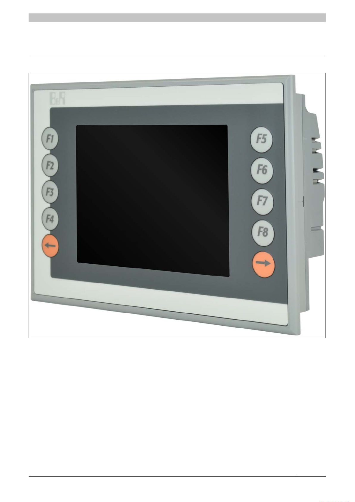
Figure 1: 4PP065.0571-B00 - Oblique view
Data sheetV 1.00 4PP065.0571-B00 3
Page 4
Views
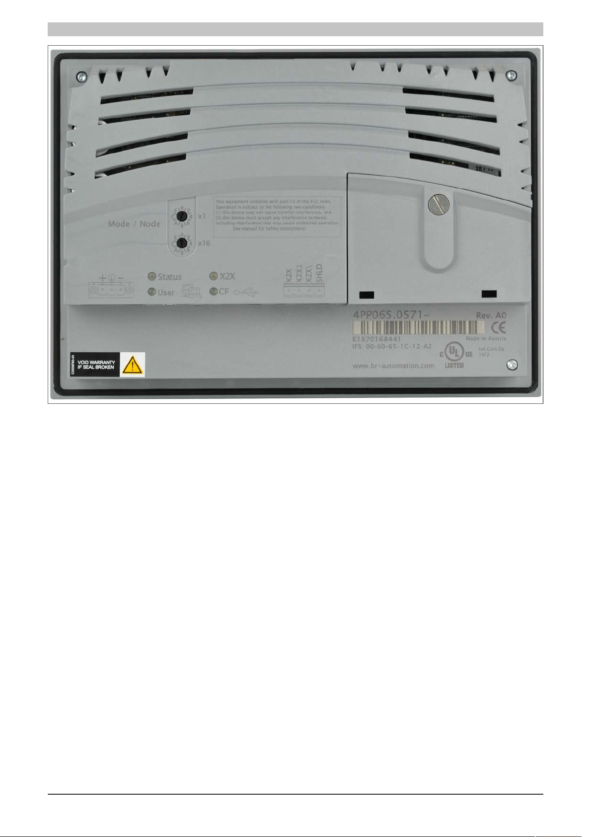
Figure 2: 4PP065.0571-B00 - Rear view
4 Data sheetV 1.00 4PP065.0571-B00
Page 5
General Information
2 General Information
Information:
B&R does its best to keep technical descriptions as current as possible. The latest version of this technical description can be downloaded in PDF format from the B&R website at www.br-automation.com.
The 4PP065.0571-B00 is a variant of the B&R standard device 4PP065.0571-X74F. Specifications that
are not listed here are identical to those for the B&R standard device and must be taken from the Power
Panel User's Manual.
2.1 Order data
Model number Short description Figure
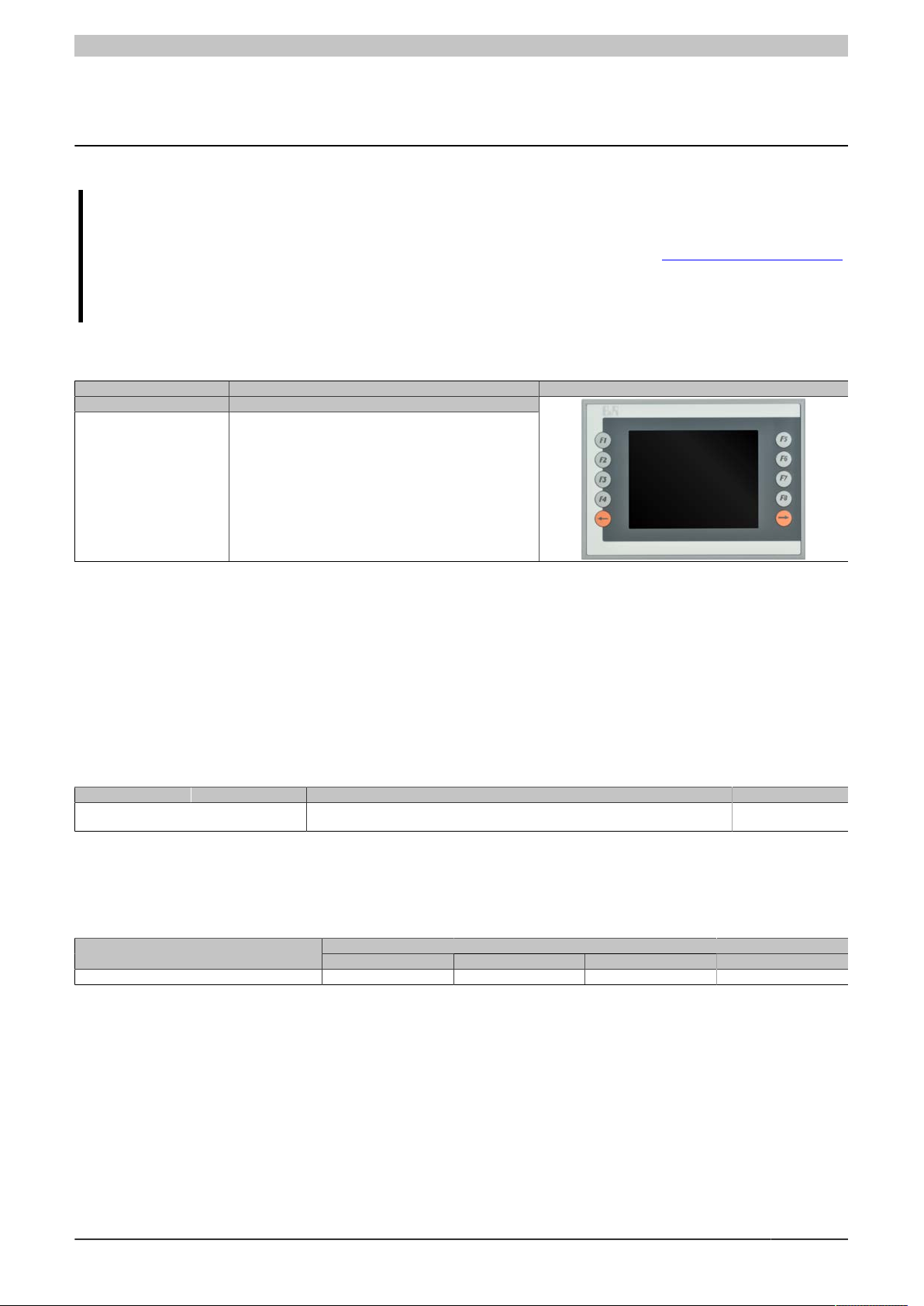
4PP065.0571-B00 cHMI PP65 TFT C QVGA 5.7in FT,X2X,ETH
Power Panel 65
Table 1: 4PP065.0571-B00 - Order data
2.1.1 Description
The 4PP065.0571-B00 is a variant of the standard device 4PP065.0571-X74F, with the following modifications:
•
Panel overlay design and slide-in labels same as standard PP45 (but PP45/PP65 imprint)
•
No embossing around display
•
Display with dim backlighting
2.1.2 Version information
Version Date Comment Responsible
1.00 (starting with
Rev. A0)
22-Jul-13 First edition Anna Sigl
Table 2: Version information
2.1.3 Supported interface modules
Support for interface modules is provided starting with the following Automation Runtime versions:
Automation Runtime version C2.96 C2.96 A3.07 C2.96
4PP065.IF10-1 4PP065.IF23-1 4PP065.IF24-1 4PP065.IF33-1
Table 3: 4PP065.0571-X74F – Supported interface modules
Data sheetV 1.00 4PP065.0571-B00 5
Interface modules
Page 6
Fully assembled device - Technical data
3 Fully assembled device - Technical data
3.1 Diagnostic LEDs
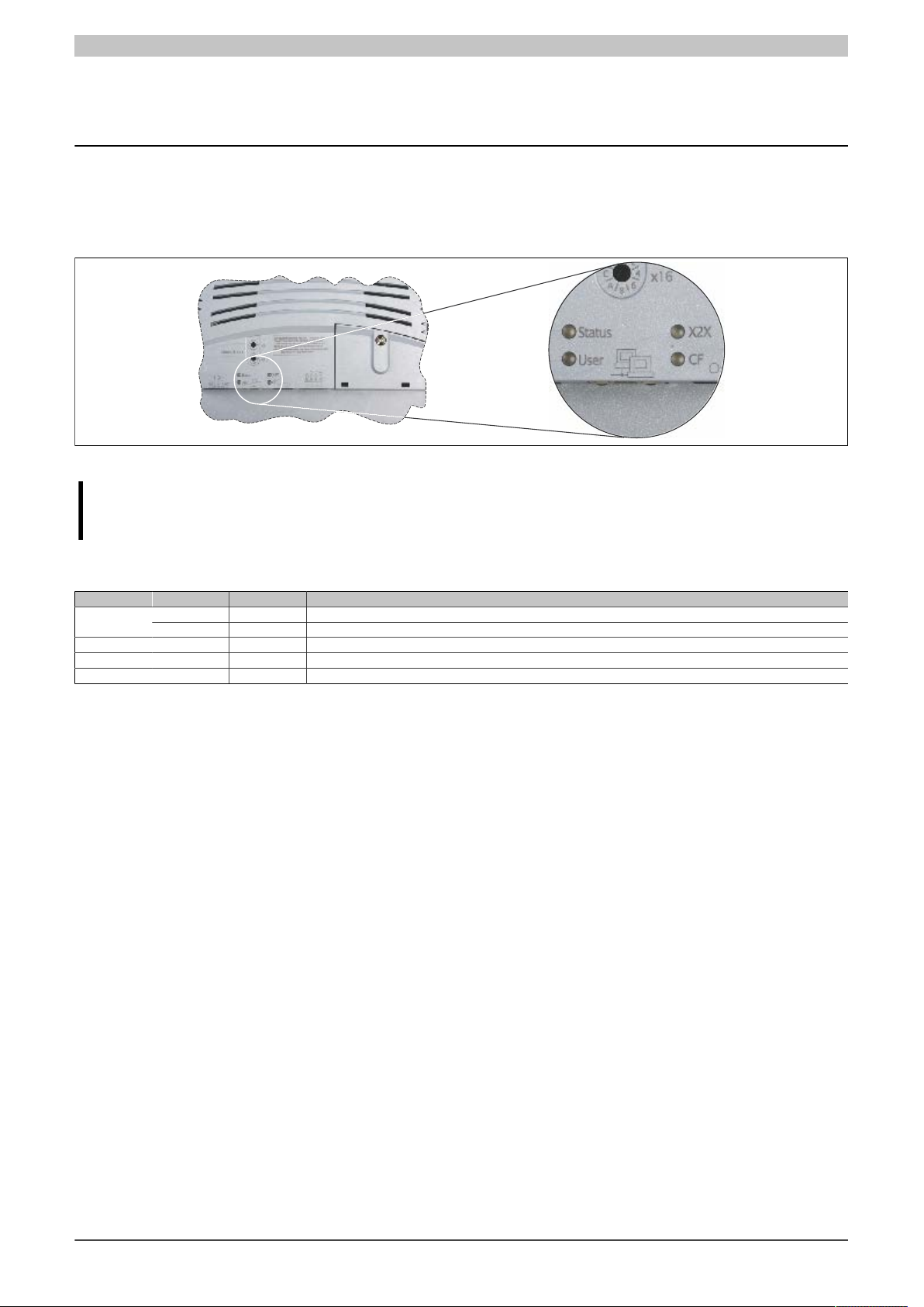
There are four diagnostic LEDs on the back of the PP65.
Figure 3: 4PP065.0571-X74F - Diagnostic LEDs
Information:
The behavior of the Status LED has changed starting with AR J2.96, E3.01 and B3.06.
3.1.1 Diagnostic LEDs up to AR I2.96, D3.01 and A3.06
LED Color Status Description
User Green On / Off LED operable by the user (with the AsHW library)
X2X Orange On Module sending data via the X2X Link interface
CF Orange On CompactFlash card being accessed
Red On Error / ResetStatus
Orange On Boot or Ready mode
Table 4: 4PP065.0571-X74F - Diagnostic LEDs up to AR I2.96, D3.01 and A3.06
6 Data sheetV 1.00 4PP065.0571-B00
Page 7
3.1.2 Diagnostic LEDs starting with AR J2.96, E3.01 and B3.06
ACT
(orange)
LNK
(green)
LED Color Status Description
Status see "Table 6: 4PP065.0571-X74F - Status LED blink code" on page 7
User Green On / Off LED operable by the user (with the AsHW library)
X2X Orange On Module sending data via the X2X Link interface
CF Orange On CompactFlash card being accessed
Table 5: 4PP065.0571-X74F - Diagnostic LEDs starting with AR J2.96, E3.01 and B3.06
Fully assembled device - Technical data
Blink codes (200 ms pattern) Description
Error / Reset
No errors, normal operation
Battery not installed or battery capacity too low
CompactFlash media not found
Reserved for future blink codes
Table 6: 4PP065.0571-X74F - Status LED blink code
Because blink codes can only signal one error at a time, errors with higher priority take precedence. Fatal errors
have a higher priority than less significant errors (e.g. low battery capacity).
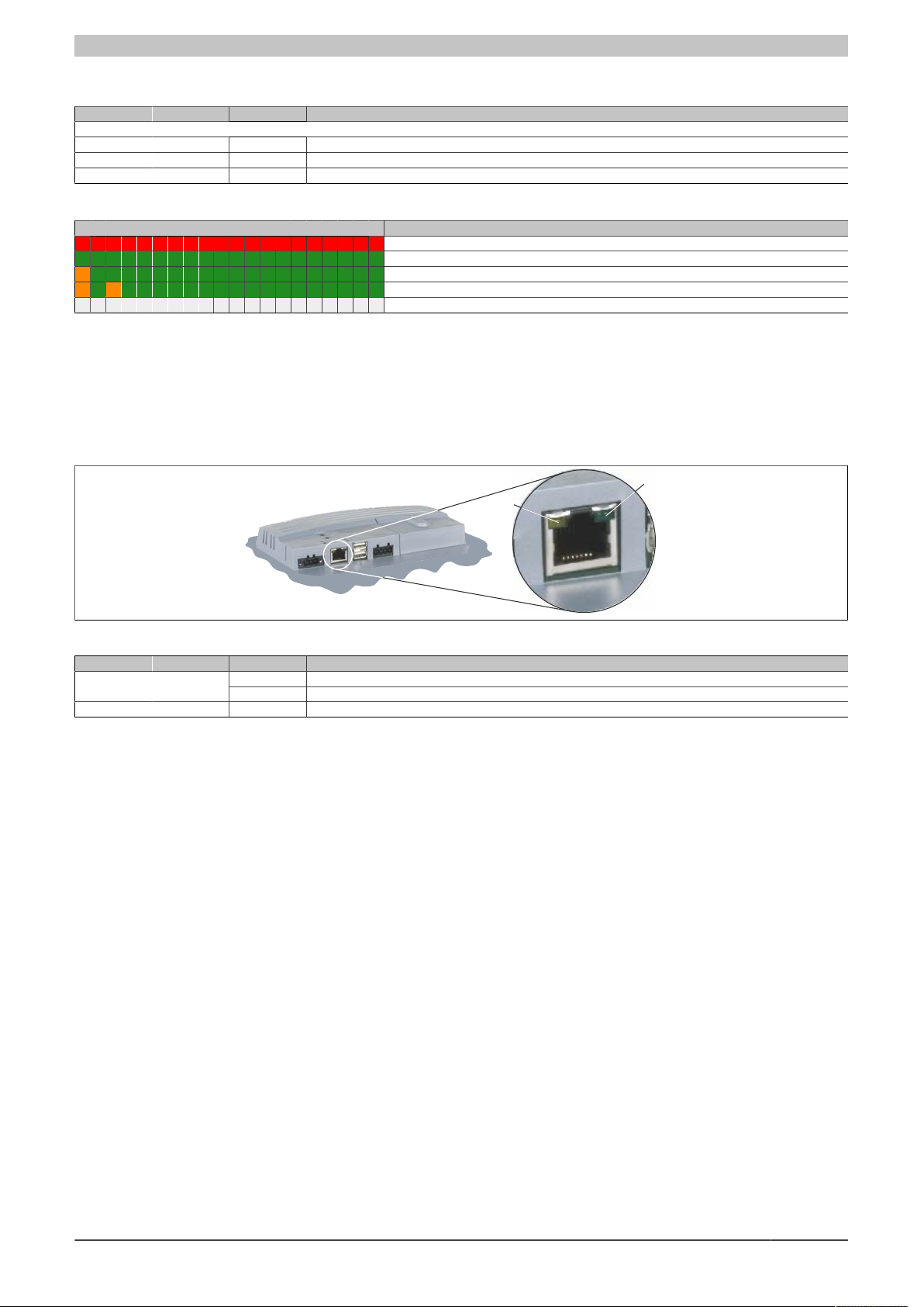
3.1.3 ACT / LNK LEDs for the RJ45 interface
There are two additional LEDs for the Ethernet interface.
Figure 4: 4PP065.0571-X74F - ACT/LNK LEDs for the RJ45 port
LED Color Status Description
LNK Green On A link to the remote station has been established.
On No Ethernet activity on the busACT Orange
Blinking Ethernet activity on the bus
Table 7: 4PP065.0571-X74F - ACT/LNK LEDs for the RJ45 port
Data sheetV 1.00 4PP065.0571-B00 7
Page 8
Fully assembled device - Technical data
Supply voltage
Ethernet interface
USB ports
X2X Link interface
X2X
X2X
X2X \
SHLD
1 2 3 4
T
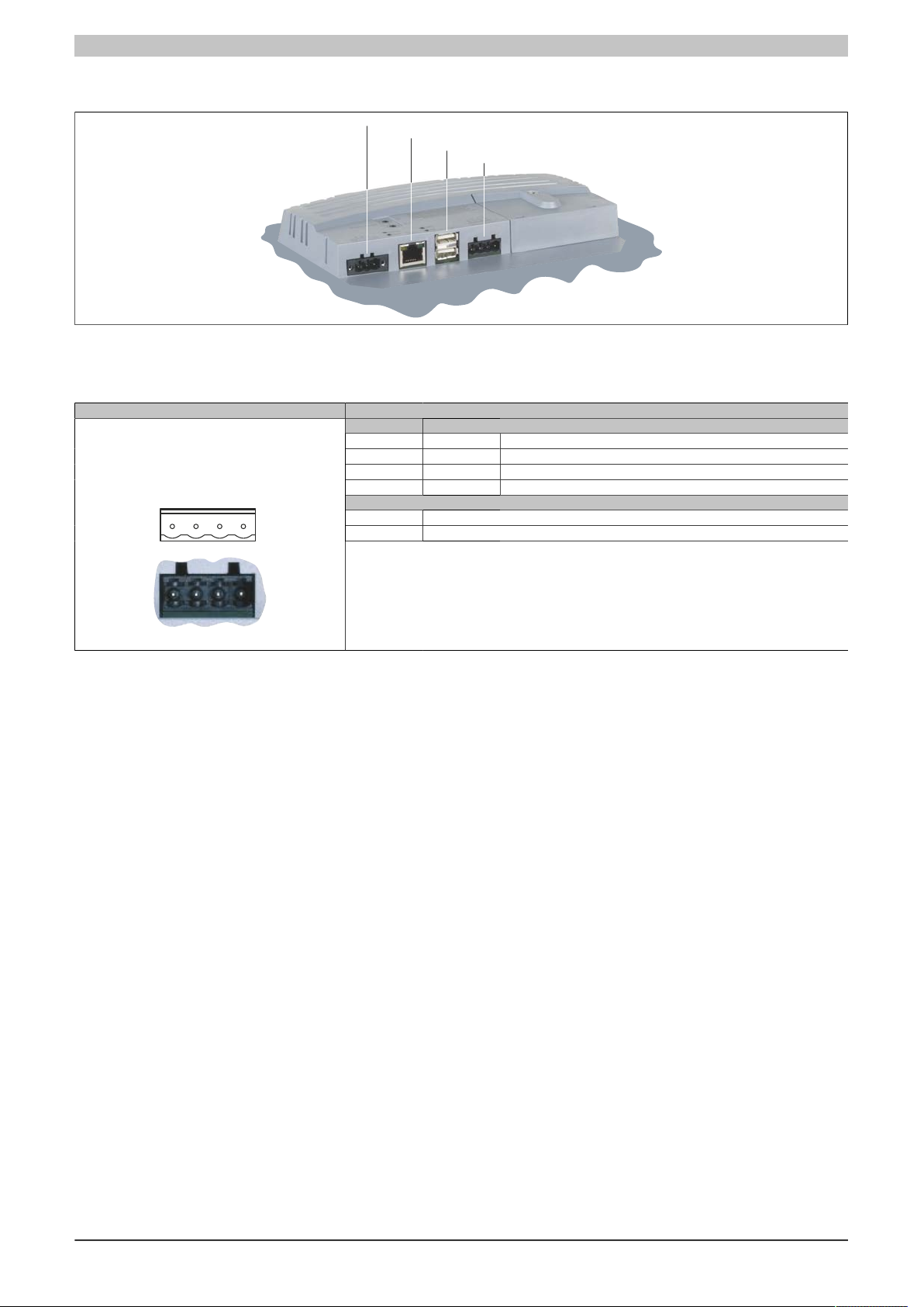
3.2 Connection elements
Figure 5: 4PP065.0571-X74F - Connection elements
3.2.1 X2X Link port
Interface Pinout
User interface
X2X Link
4-pin male multipoint connector
Terminal X2X Link
1 X2X X2X data
2 X2X X2X ground
3 X2X\ X2X data inverted
4 SHLD Shield
Required accessories
0TB704.9 Terminal block accessory, 4-pin, screw clamp, 1.5 mm²
0TB704.91 Terminal block accessory, 4-pin, cage clamp, 2.5 mm²
Table 8: 4PP065.0571-X74F - X2X Link pinout
8 Data sheetV 1.00 4PP065.0571-B00
Page 9
Fully assembled device - Technical data
USB port 1
USB port 2
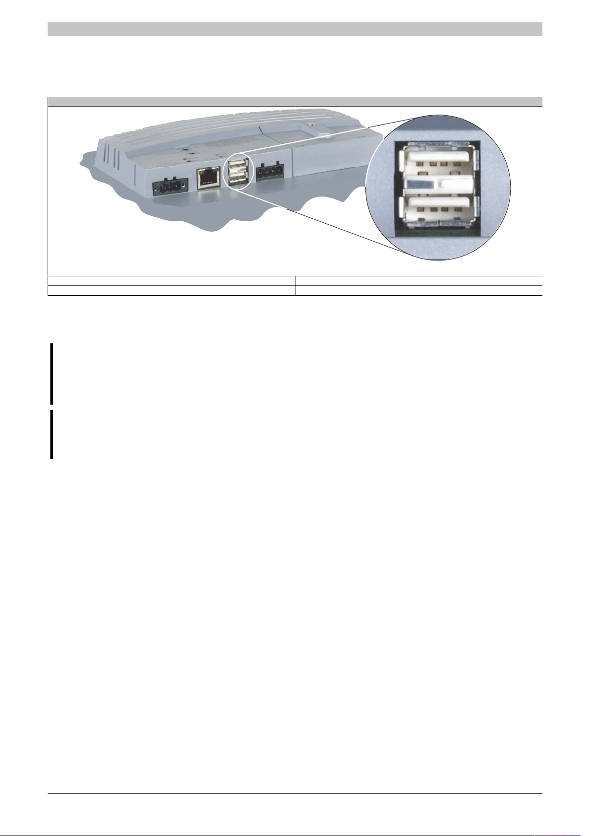
3.2.2 USB ports
This Power Panel 65 device features a USB 2.0 (Universal Serial Bus) host controller with two USB ports that are
accessible externally.
USB interface
Transfer rate
Power supply Max. 500 mA per port
1)
Low speed (1.5 Mbit/s), full speed (12 Mbit/s), high speed (480 Mbit/s)
2)
Table 9: 4PP065.0571-X74F - USB interface
1) The actual value depends on the operating system or driver being used.
2) Each USB port is protected by a maintenance-free "USB current-limiting circuit breaker" (max. 500 mA).
Warning!
Peripheral USB devices can be connected to these USB ports. Due to the vast number of USB devices
available on the market, B&R cannot guarantee their performance. B&R does ensure the performance
of all USB devices that they provide.
Caution!
Because this interface is designed according to general PC specifications, extreme care should be
exercised with regard to EMC, cable routing, etc.
Data sheetV 1.00 4PP065.0571-B00 9
Page 10
Fully assembled device - Technical data
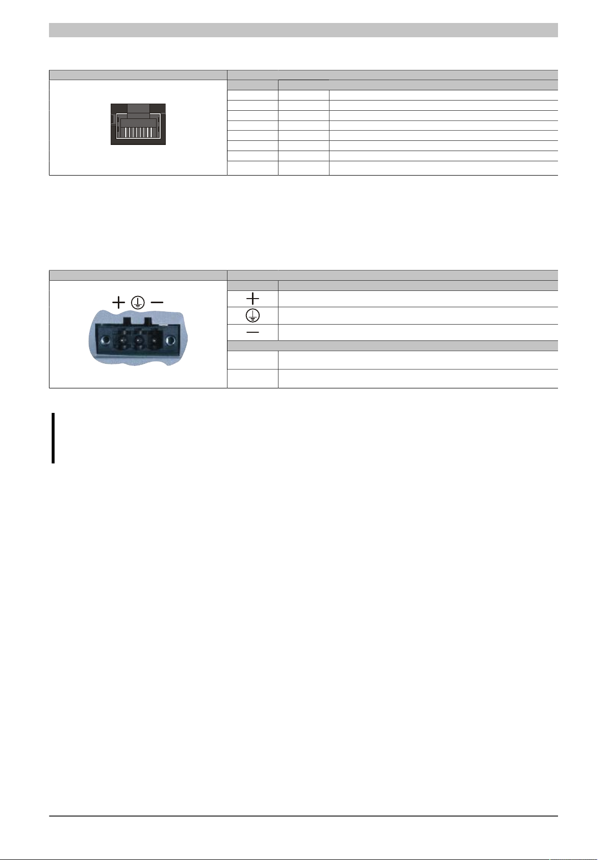
3.2.3 Ethernet interface
Interface Pinout
Ethernet interface
RJ45 twisted pair socket
(10BaseT/100BaseT)
Terminal
1 RXD Receive signal
2 RXD\ Receive signal inverted
3 TXD Transmit signal
4 Termination Termination
5 Termination Termination
6 TXD\ Transmit signal inverted
7 Termination Termination
8 Termination Termination
Table 10: 4PP065.0571-X74F - Ethernet interface pinout
3.2.4 Supply voltage
The pinout can be found either in the following table or printed on the back of the Power Panel. The Power Panel
has reverse polarity protection that prevents the supply voltage from being connected incorrectly and damaging
the device. Overload protection must be provided by an external fuse (5 A, fast-acting).
Supply voltage Pinout
3-pin multipoint plug
Table 11: 4PP065.0571-X74F - Supply voltage pinout
Terminal Assignment
+ 24 VDC
Functional ground
GND
Required accessories
0TB103.9 Connector, 24 VDC, 3-pin female, 3.31 mm² screw clamp, protected against vibration
by the screw flange
0TB103.91 Connector, 24 VDC, 3-pin female, 3.31 mm² cage clamp, protected against vibration by
the screw flange
Caution!
The functional ground must be connected to ground (e.g. control cabinet) using the shortest possible
path. Using the largest possible conductor cross section on the supply plug is recommended.
10 Data sheetV 1.00 4PP065.0571-B00
Page 11
Fully assembled device - Technical data
3.2.5 Operating mode and node number switches
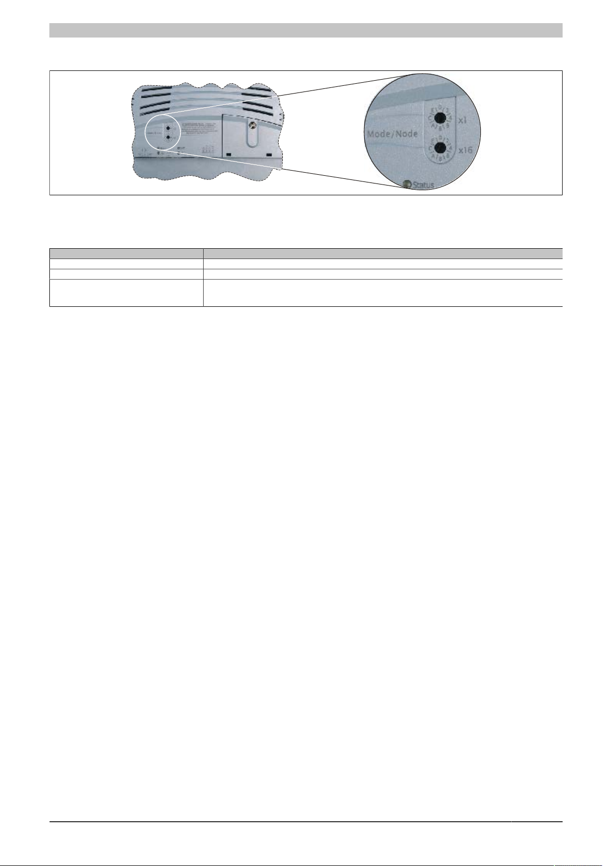
Figure 6: 4PP065.0571-X74F - Operating mode and node number switches
The Power Panel 65 device is equipped with 2 hex switches that can be used as operating mode or node number
switches. Switch positions 01 - FE are used to set the INA station number of the Ethernet interface.
Switch position Description
00 Reserved
01 - FE INA node number of the Ethernet interface
FF Diagnostics mode:
Table 12: 4PP065.0571-X74F - Operating mode and node number switches
The CPU boots in Diagnostics mode. Does not initialize program sections in User RAM and User FlashPROM.
After being in diagnostics mode, the CPU always boots with a cold restart.
Data sheetV 1.00 4PP065.0571-B00 11
Page 12
Fully assembled device - Technical data
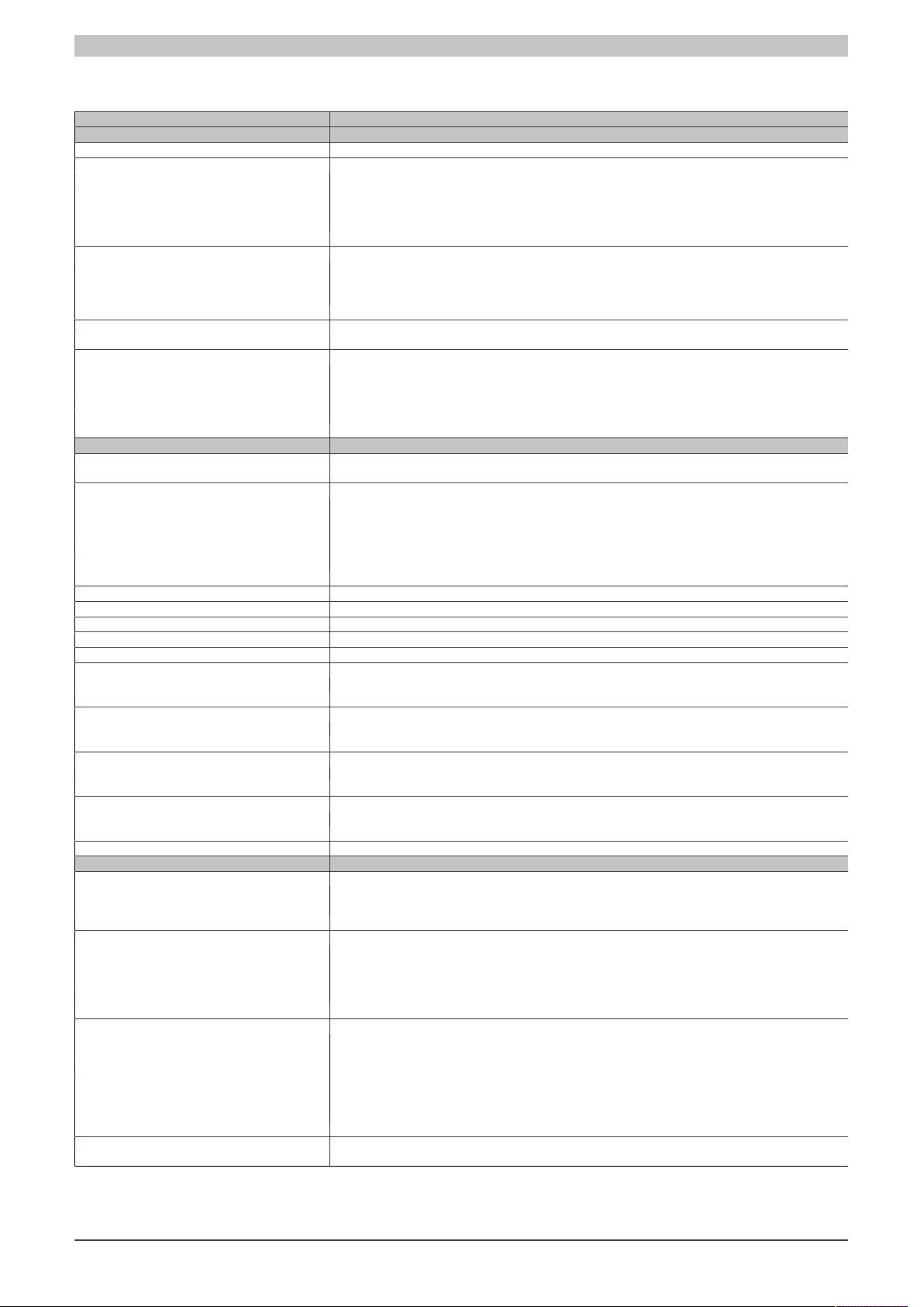
3.3 Technical data
Product ID 4PP065.0571-B00
General information
B&R ID code $E187
LEDs
Quantity 4
CF (CompactFlash) Orange
Status Red/Green
X2X Orange
User Green
Battery
Type Renata 950 mAh
Service life 4 years
Removable Yes, accessible from the outside
Design Lithium Ion
Backup capacitor
Buffer time 10 min
Certification
CE Yes
cULus Yes
CE Yes
cULus Yes
GOST-R Yes
Controller
Boot loader, operating system
PP65 supported beginning with version Automation Runtime, C2.96
Processor
Type Geode LX800, 32-bit x86
Clock frequency 500 MHz
L1 cache 128 kB (64 kB I-cache / 64 kB D-cache)
L2 cache 128 kB
Expanded command set MMX technology, 3D Now
Floating point unit (FPU) Yes
Flash 4 MB (for firmware)
Cooling Passive via heat sink
Mode/Node switches 2, 16 positions each
Remanent variables 32 kB
Watchdog MTCX
Real-time clock
Accuracy At 25°C: typ. 30 ppm (2.5 seconds) per day
Battery-buffered Yes
Power failure logic
Controller MTCX
Buffer time 10 ms
Graphics
Controller Geode LX800
Memory 8 MB shared memory (allocated in RAM)
Standard memory
RAM 128 MB DDR SDRAM
User RAM 200 kB SRAM
PP65 Compact IF slot 1
Interfaces
CompactFlash slot 1
Quantity 1
Type Type I
Design Primary IDE device
USB
Quantity 2
Type USB 1.1, USB 2.0
Design Type A
Transfer rate Low speed (1.5 Mbit/s), full speed (12 Mbit/s), high speed (480 Mbit/s)
Current load Max. 500 mA per connection
Ethernet
Quantity 1
Controller Intel 82551ER
Design Shielded RJ45 port (10/100 Base-T)
Transfer rate 10/100 Mbit/s
Max. baud rate 100 Mbit/s
Cables S/STP (Category 5)
Status LEDs Link/Activity
X2X
Design 4-pin male multipoint connector
Table 13: 4PP065.0571-B00 - Technical data
1)
2)
3)
2)
12 Data sheetV 1.00 4PP065.0571-B00
Page 13
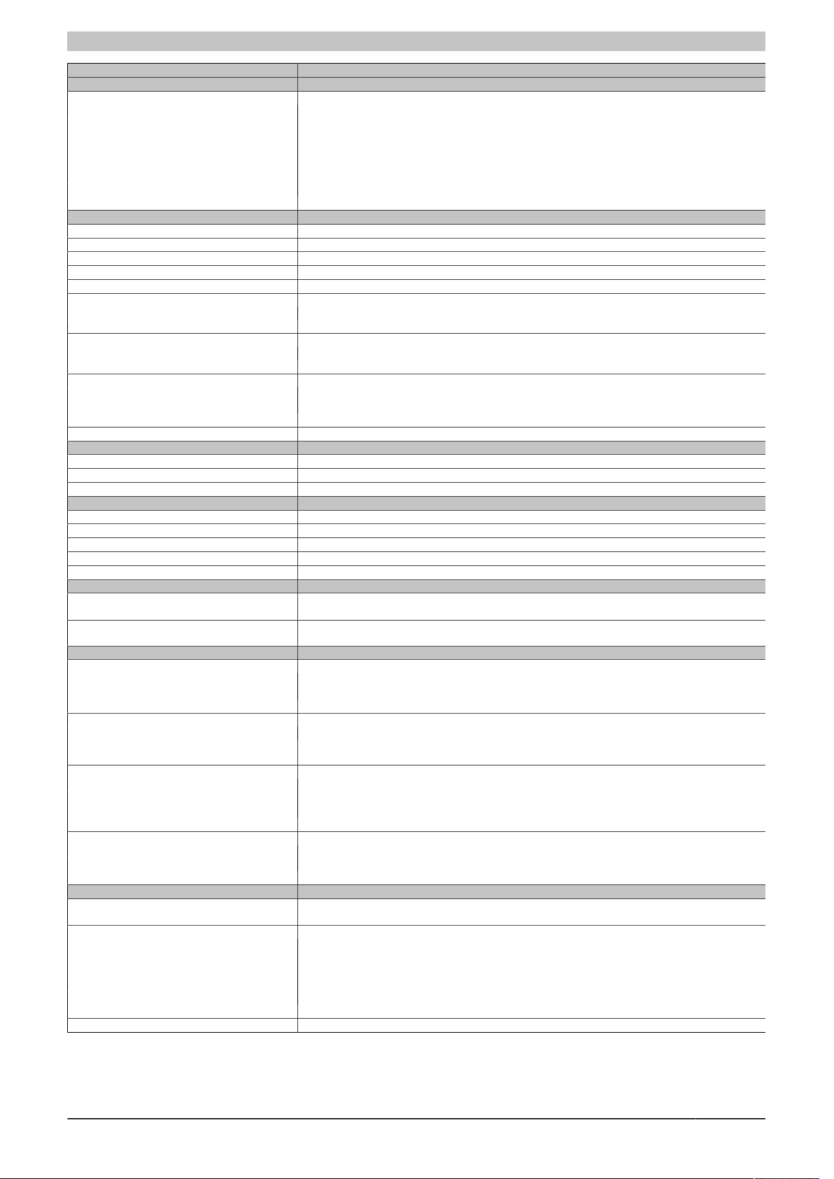
Fully assembled device - Technical data
Product ID 4PP065.0571-B00
Product ID
X2X
Quantity 1
Type X2X Link master
Design 4-pin male multipoint connector
Number of stations Max. 253
Distance between stations Max. 100 m
Network topology Line
Internal bus supply No
Bus terminating resistor Internal
Display
Type Color TFT
Diagonal 5.7" (144 mm)
Colors 262,144
Resolution QVGA, 320 x 240 pixels
Contrast 350:1
Viewing angles
Horizontal Direction R / Direction L = 60°
Vertical Direction U = 65° / Direction D = 50°
Backlight
Brightness 250 cd/m²
Half-brightness time 50,000 h
Touch screen
Technologies Analog, resistive
Controller B&R, 12-bit
Transmittance 70% ±10%
Screen rotation Yes
Keys
Design Membrane keypad with metallic snap-action disks
Total keys 10 membrane keys
Function keys 10 (with slide-in labels)
Electrical characteristics
Nominal voltage 24 VDC ±25%
Nominal current 0.45 A
Starting current Max. 2.8 A
Power consumption Typ. 10 W
Electrical isolation No
Operating conditions
Installation at altitudes above sea level
Maximum 3000 m
Protection in accordance with EN 60529 Back: IP20 (only with an inserted CompactFlash card)
Front: IP65 / NEMA 250 type 4X, dust and sprayed water protection
Environmental conditions
Temperature
Operation 0 to 50°C
Storage -20 to 70°C
Transport -20 to 70°C
Relative humidity
Operation 10 to 90%, non-condensing
Storage T ≤ 40°C: 5 to 90%, non-condensing
T > 40°C: <90%, non-condensing
Vibration
Operation (continuous) 2 to 9 Hz: 1.75 mm amplitude / 9 to 200 Hz: 0.5 g
Operation (occasional) 2 to 9 Hz: 3.5 mm amplitude / 9 to 200 Hz: 1 g
Storage 2 to 8 Hz: 7.5 mm amplitude / 8 to 200 Hz: 2 g / 200 to 500 Hz: 4 g
Transport 2 to 8 Hz: 7.5 mm amplitude / 8 to 200 Hz: 2 g / 200 to 500 Hz: 4 g
Shock
Operation 15 g, 11 ms
Storage 30 g, 15 ms
Transport 30 g, 15 ms
Mechanical characteristics
Housing
Material Polyester
Front
Design B&R design
Panel membrane
Material Polyester
Light background Pantone 427 C
Dark gray border around display Pantone 432 C
Color legend strips Pantone 428 C and Pantone 151 C
Front Multi-layered overlay with insertion slots for key labels
Table 13: 4PP065.0571-B00 - Technical data
4)
Data sheetV 1.00 4PP065.0571-B00 13
Page 14

Fully assembled device - Technical data
Product ID 4PP065.0571-B00
Dimensions
Width 203 mm
Height 145 mm
Depth 56.5 mm
5)
Weight
Table 13: 4PP065.0571-B00 - Technical data
1) Typical service life (at 50% buffer operation, 25°C when device off, 50°C when device on).
Maximum service life in 24h operation (no buffer): 6 years at 25°C, 5 years at 50°C.
Maximum service life when device switched off: 2 years at 25°C, 1 year at 50°C.
2) Maintenance Controller Extended.
3) At max. specified ambient temperature: typ. 50 ppm (4 s), worst case 100 ppm (8 s).
4) The actual number of colors depends on the graphics memory, the graphics mode set and the graphics driver used.
5) Weight including fasteners and battery (46.5 g) but without an interface module
0.75 kg
14 Data sheetV 1.00 4PP065.0571-B00
Page 15
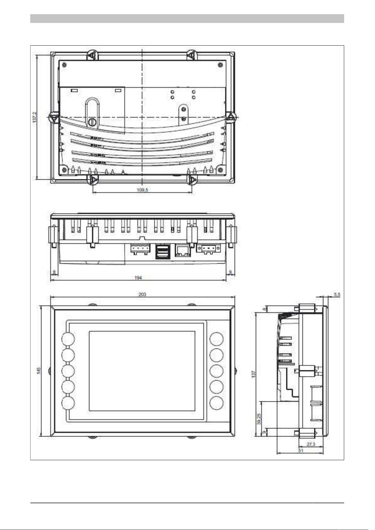
3.4 Dimensions
Fully assembled device - Technical data
Figure 7: 4PP065.0571-B00 - Dimensions
Data sheetV 1.00 4PP065.0571-B00 15
Page 16
Fully assembled device - Technical data
Outer contour (Power Panel)
Cutout
Cutout dimensions
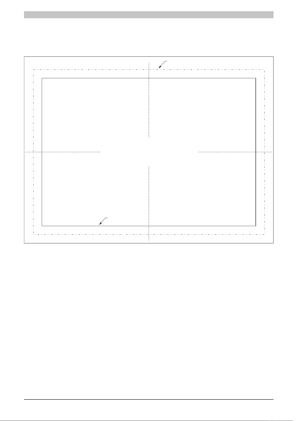
188 ±0.5 mm x 130 ±0.5 mm
3.5 Cutout installation
The cutout hole must to be made according to the following dimensions for cutout installations. These devices are
best mounted in a cutout installation using the mounting clips on the housing or clamping blocks (various designs
possible).
Figure 8: 4PP065.0571-B00 - Cutout installation
16 Data sheetV 1.00 4PP065.0571-B00
Page 17
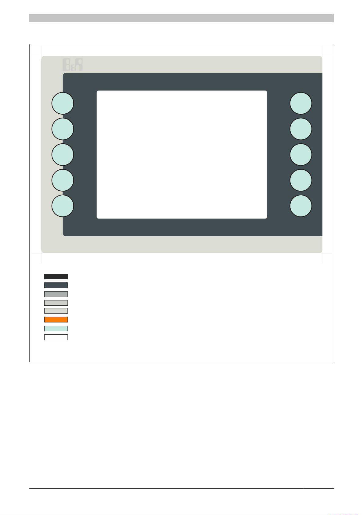
3.6 Panel overlay design
= Pantone 429 C
IMPORTANT:
This image is not a true representation of the colors used on the panel overlay.
The actual colors may vary slightly.
Color description:
= Pantone 427 C
= Pantone 428 C
= Transparent / unprinted
= Pantone Process black C
= Cutout
= Pantone 432 C
= Pantone 151 C
Fully assembled device - Technical data
Figure 9: 4PP065.0571-B00 - Panel overlay design
Data sheetV 1.00 4PP065.0571-B00 17
Page 18
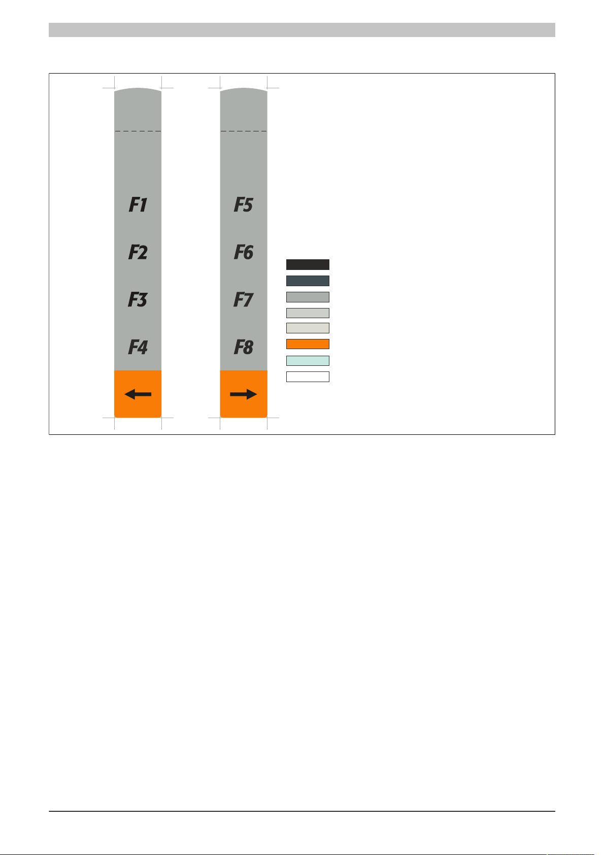
Fully assembled device - Technical data
= Pantone 429 C
IMPORTANT:
This image is not a true representation of the colors used on the panel overlay.
The actual colors may vary slightly.
Color description:
= Pantone 427 C
= Pantone 428 C
= Transparent / unprinted
= Pantone Process black C
= Cutout
= Pantone 432 C
= Pantone 151 C
3.7 Slide-in labels
Figure 10: 4PP065.0571-B00 - Slide-in labels
18 Data sheetV 1.00 4PP065.0571-B00
Page 19
Commissioning
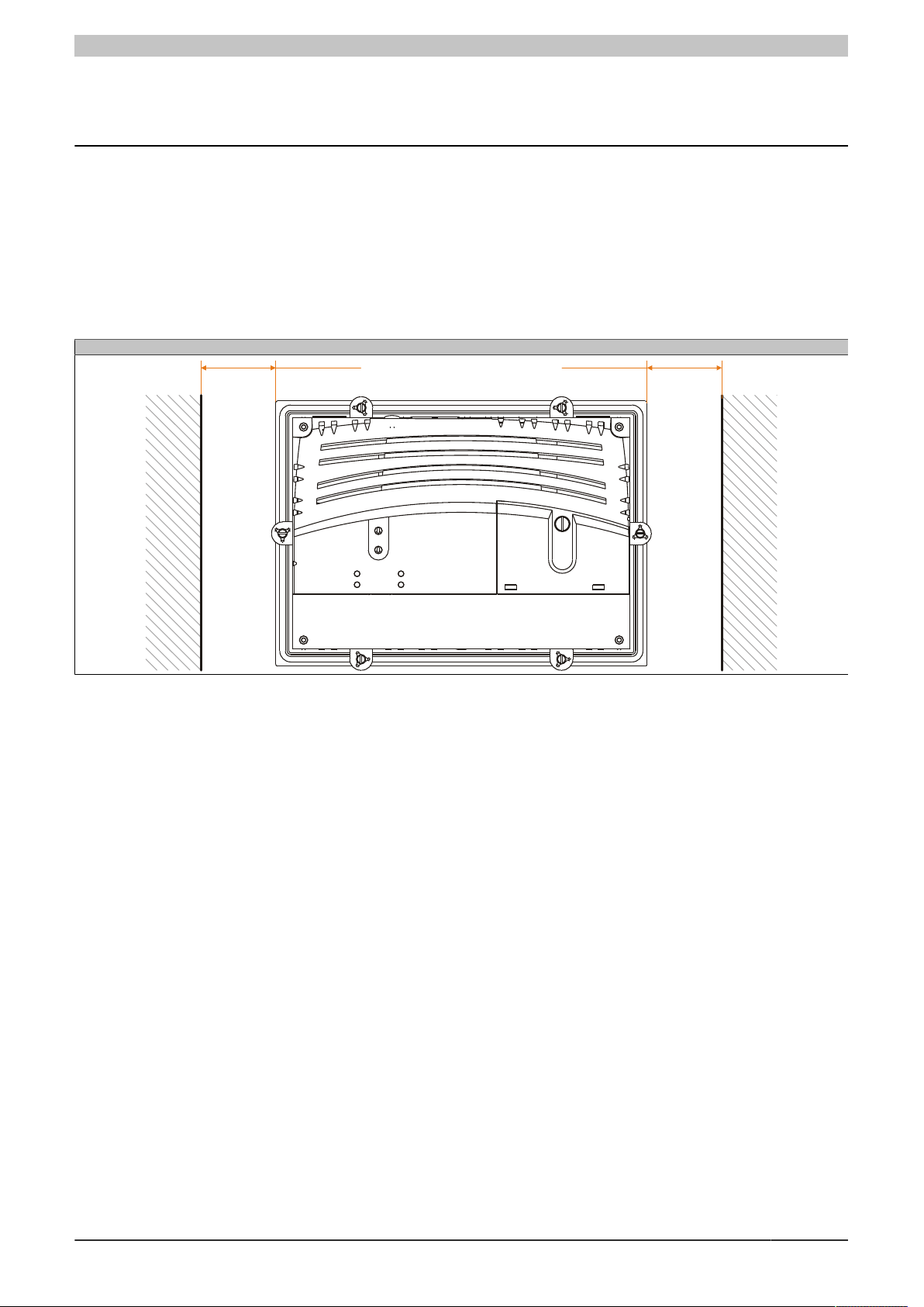
At least
40 mm spacing
At least
40 mm spacing
4 Commissioning
4.1 Mounting instructions
The Power Panel must be mounted using the retaining clips included in delivery (with a torque of 0.6 Nm). Each
Power Panel comes with six retaining clips (two each for top/bottom and one each for left/right).
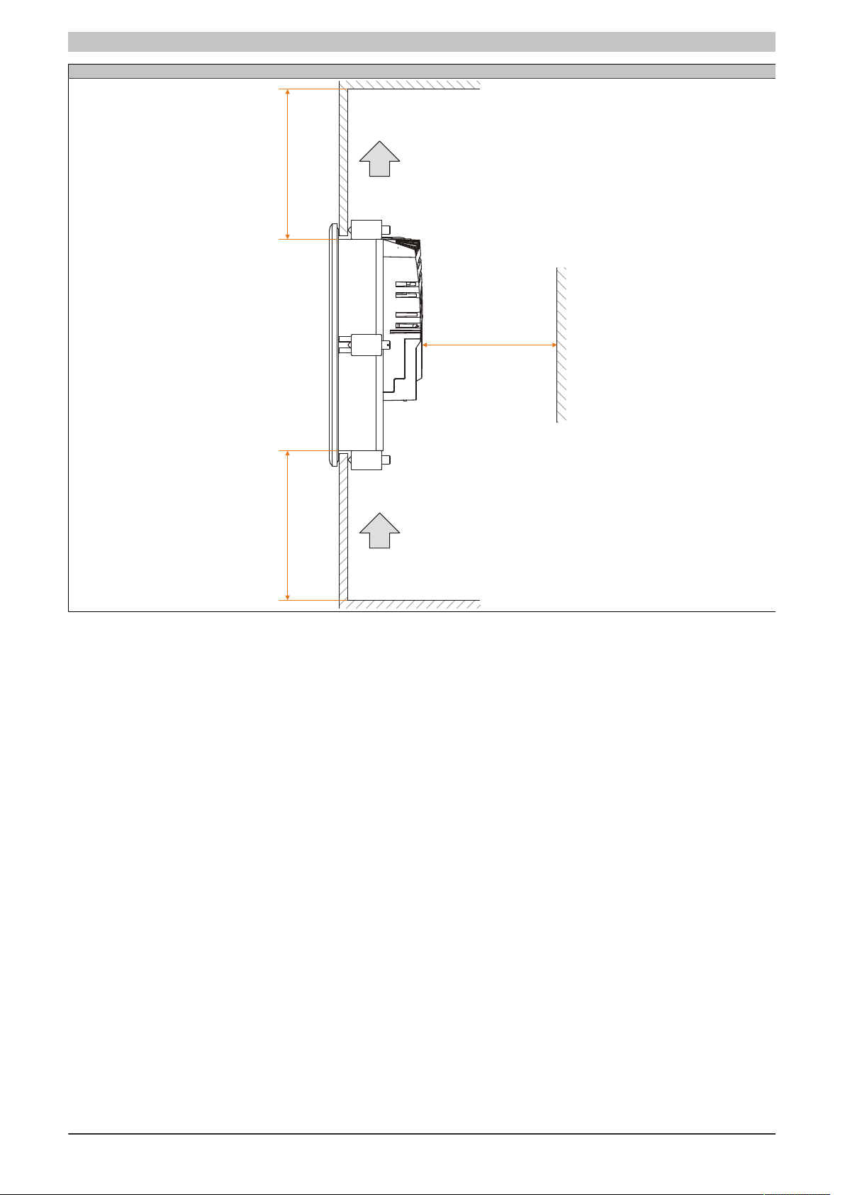
In order to guarantee sufficient air circulation, allow the specified amount of space above, below, to the side and
behind the Power Panel. The minimum specified spacing is indicated in the following diagrams. This applies to
all Power Panel variants.
Rear view
Table 14: Spacing for air circulation - Rear view
Data sheetV 1.00 4PP065.0571-B00 19
Page 20
Commissioning
Air inlet
Air outlet
At least
80 mm spacing
At least
80 mm spacing
At least
80 mm spacing
Side view
Table 15: Spacing for air circulation - Side view
20 Data sheetV 1.00 4PP065.0571-B00
Page 21
Commissioning
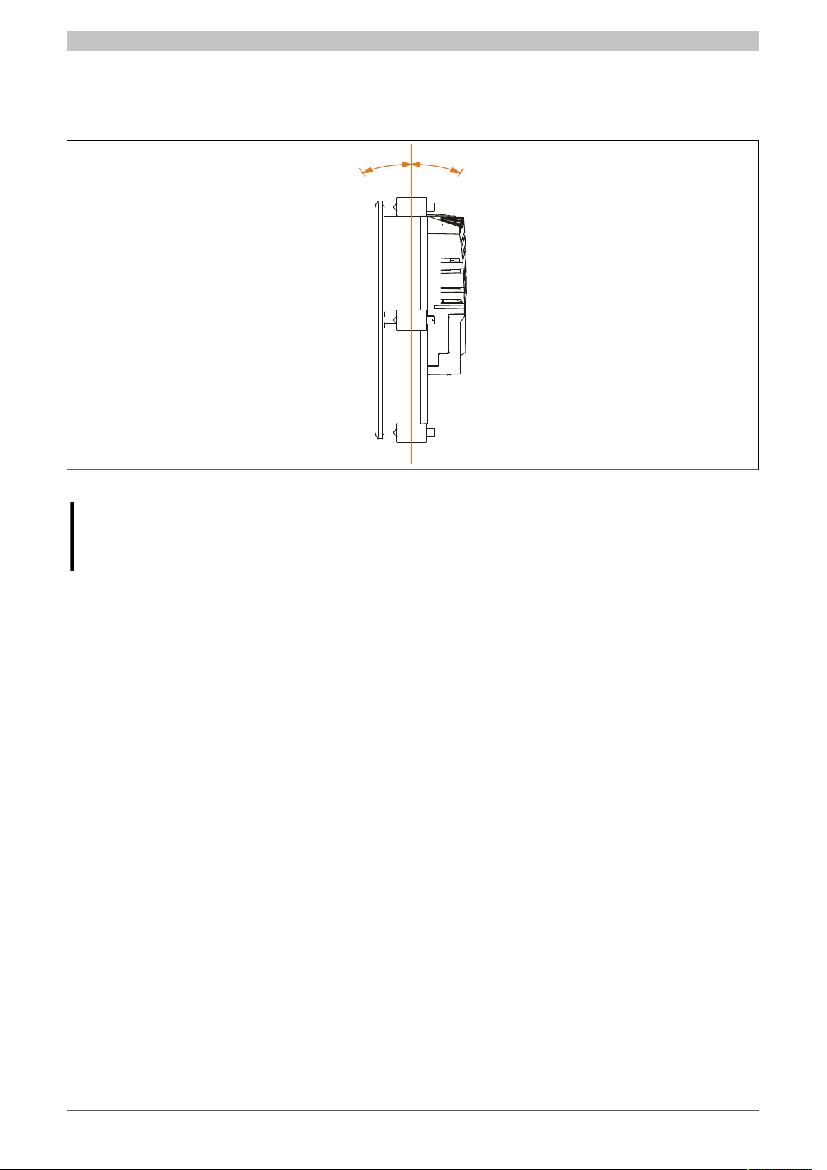
45°
45°
4.2 Mounting orientation
The following diagram shows the approved mounting orientations for Power Panel devices. These mounting orientations apply to all Power Panel variants.
Figure 11: Power Panel - Mounting orientations
Caution!
The maximum permitted ambient temperature can be found in the technical data for the respective
Power Panel device.
Data sheetV 1.00 4PP065.0571-B00 21
Page 22
Commissioning
①
②
③
④
⑤
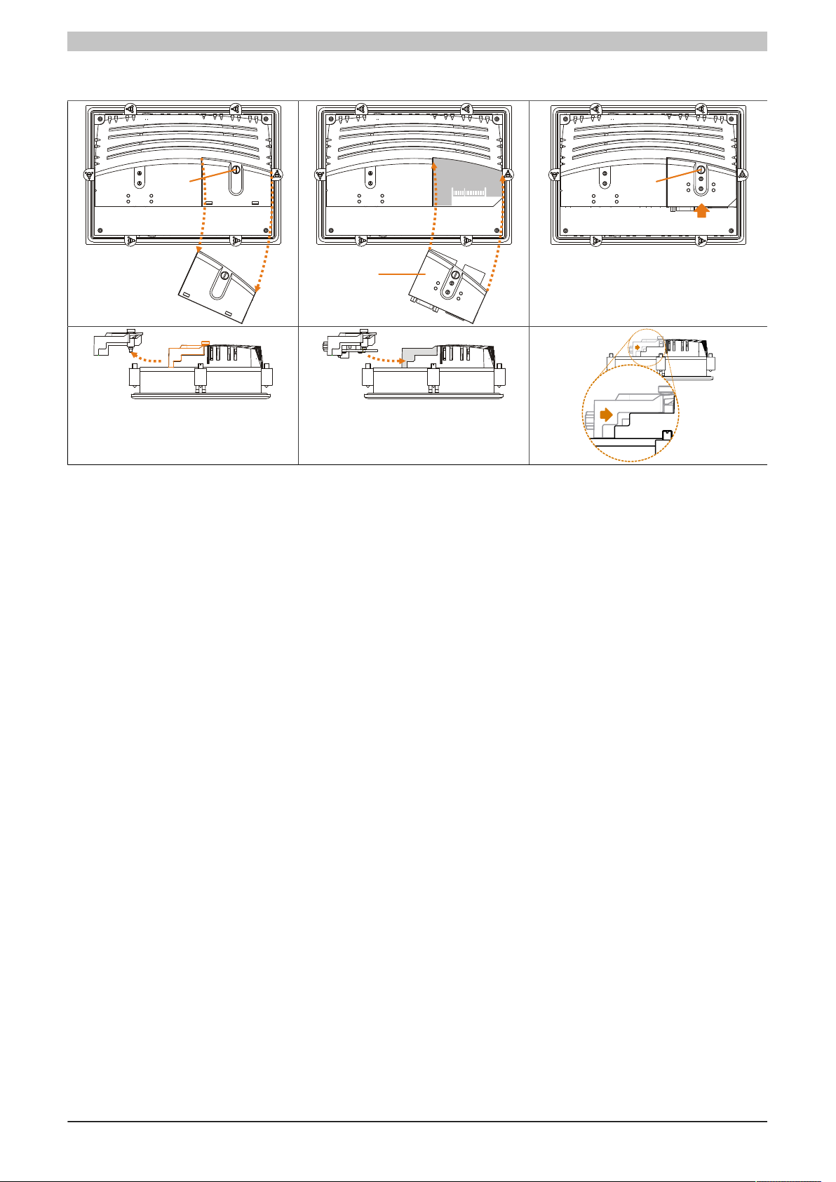
4.3 Installing interface modules
Table 16: Installing PP65 interface modules in the Power Panel 65
1) Remove the screws from the cover.
2) Remove the cover.
3) Insert the interface module into the PP65.
4) Apply light pressure until the interface module is inserted all the way.
5) Secure the interface module with the screws (max. 0.6 Nm).
4.4 Touch screen calibration
B&R touch screen devices are equipped with a touch controller that supports hardware calibration. As a result,
devices are pre-calibrated when delivered. This is an advantageous feature when replacing devices of the same
model or type since it avoids having to recalibrate the new device. Nevertheless, calibrating the device is still
recommended in order to achieve the best results and to better adapt the touch screen to the user's preferences.
4.5 Screen rotation
It is possible to rotate screen contents by 90° using the graphic driver's screen rotation function. Automation Runtime supports this function.
In Automation Studio 2.7.x or 3.0.x, the screen orientation can be defined when a project is created as well as
later when editing the project.
22 Data sheetV 1.00 4PP065.0571-B00
Page 23

Maintenance
5 Maintenance
5.1 Cleaning
Danger!
Power Panel devices may only be cleaned when switched off in order to prevent unintended functions
from being triggered when handling the touch screen or pressing keys.
Power Panel devices should be cleaned with a moist cloth. The cloth should be moistened with water and detergent,
a screen cleaning agent or alcohol (ethanol). The cleaning agent should be applied to the cloth beforehand, not
sprayed directly on the Power Panel device! Aggressive solvents, chemicals, scouring agents, pressurized air or
steam jets should never be used.
Information:
Displays with a touch screen should be cleaned regularly.
5.2 Changing the battery
5.2.1 General information
The battery buffers the internal real-time clock (RTC) and SRAM data (remanent and permanent variables, User
RAM). The battery's buffer lifespan is at least 3 years (at 50°C, 18.5 μA for the components being supplied and
a self-discharge of 40%).
It is only necessary to change the battery on devices with a lithium battery (see the technical data for the Power
Panel device).
5.2.2 Battery status evaluation
The status of the battery is determined immediately after the Power Panel is started and subsequently checked
by the system every 24 hours. During this measurement, the battery is subjected to a brief load (approximately 1
second) and then evaluated. Once determined, the battery status can be read in a customer application using the
BatteryStatusCPU data point or the HwGetBatteryInfo function (AsHW library).
Battery status Description
OK Data buffering is intact.
BAD From the point when battery capacity is recognized as insufficient (BAD), data buffering is intact for approximately
From the point when battery capacity is recognized as insufficient, data buffering is intact for approximately another
500 hours
another 500 hours
Table 17: Battery status
Information:
The battery should only be changed by qualified personnel.
Data sheetV 1.00 4PP065.0571-B00 23
Page 24
Maintenance
1
2
Correct
Incorrect
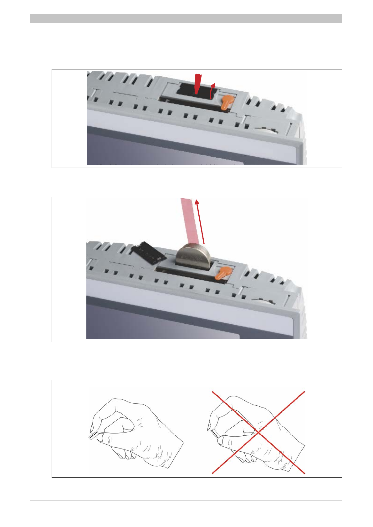
5.2.3 Procedure for changing the battery
•
Disconnect the power supply to the Power Panel.
•
Touch the housing or ground connection in order to discharge any electrostatic charge from your body.
•
Remove the battery cover from the top of the Power Panel device using a screwdriver (1).
Figure 12: Changing the battery - Removing the battery cover
•
Carefully remove the used battery from its fitting by pulling the removal strip (2).
Figure 13: Changing the battery - Removing the battery
•
In order to prevent a short circuit, do not touch the new battery with pliers or uninsulated tweezers. The
battery should not be held by its edges.
Figure 14: Battery handling
24 Data sheetV 1.00 4PP065.0571-B00
Page 25
Maintenance
1
3
2
•
Insert the new battery with the correct polarity. To make the next battery change easier, be sure the removal
strip is in place when inserting the battery.
•
Replace the battery cover.
•
Reconnect the power supply to the Power Panel.
•
Reset the date and time (using B&R Automation Studio).
Warning!
Lithium batteries are considered hazardous waste. Used batteries should be disposed of in accordance
with applicable local regulations.
5.3 Changing the CompactFlash card
5.3.1 Removing the CompactFlash card
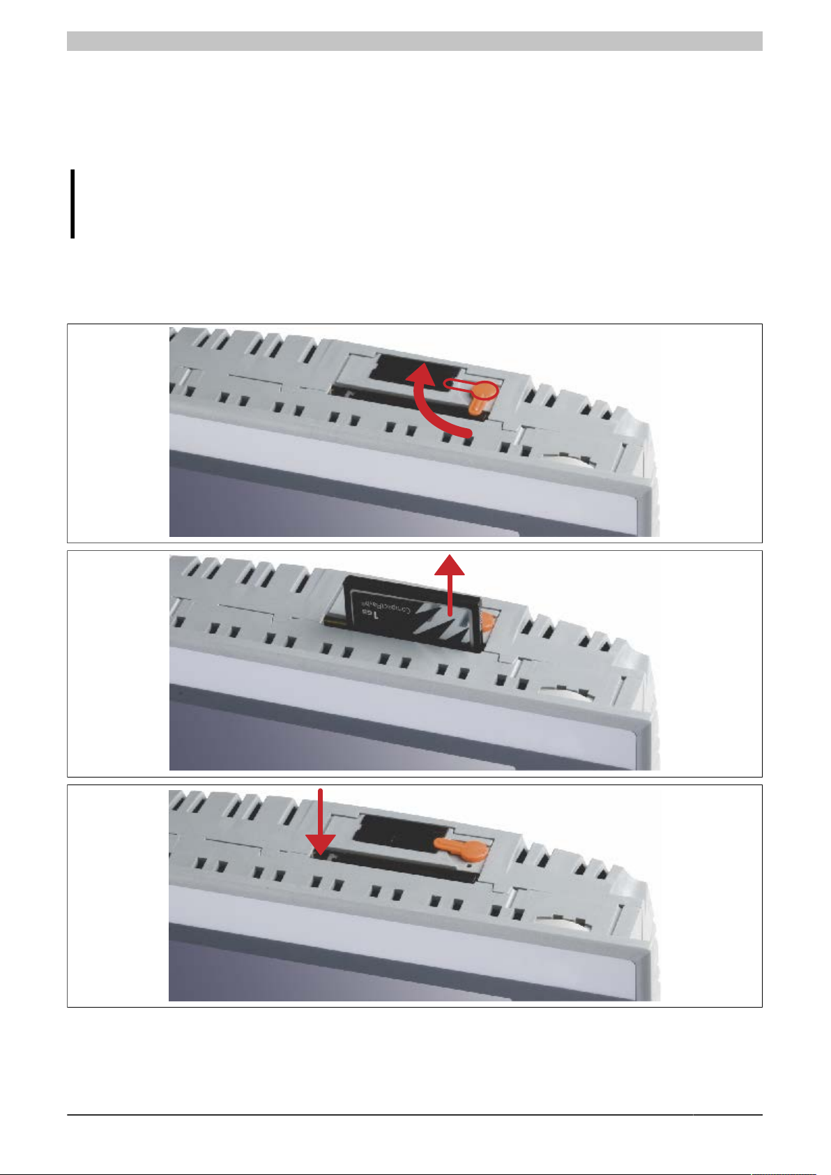
Rotate the orange CompactFlash safety latch away from the CompactFlash slot (1). Then press the CompactFlash
ejection lever with a screwdriver (2) until the CompactFlash card is ejected. The CompactFlash card can now be
removed by hand (3).
Data sheetV 1.00 4PP065.0571-B00 25
Figure 15: Removing the CompactFlash card
Page 26
Maintenance
12
3
4
5.3.2 Inserting the CompactFlash card
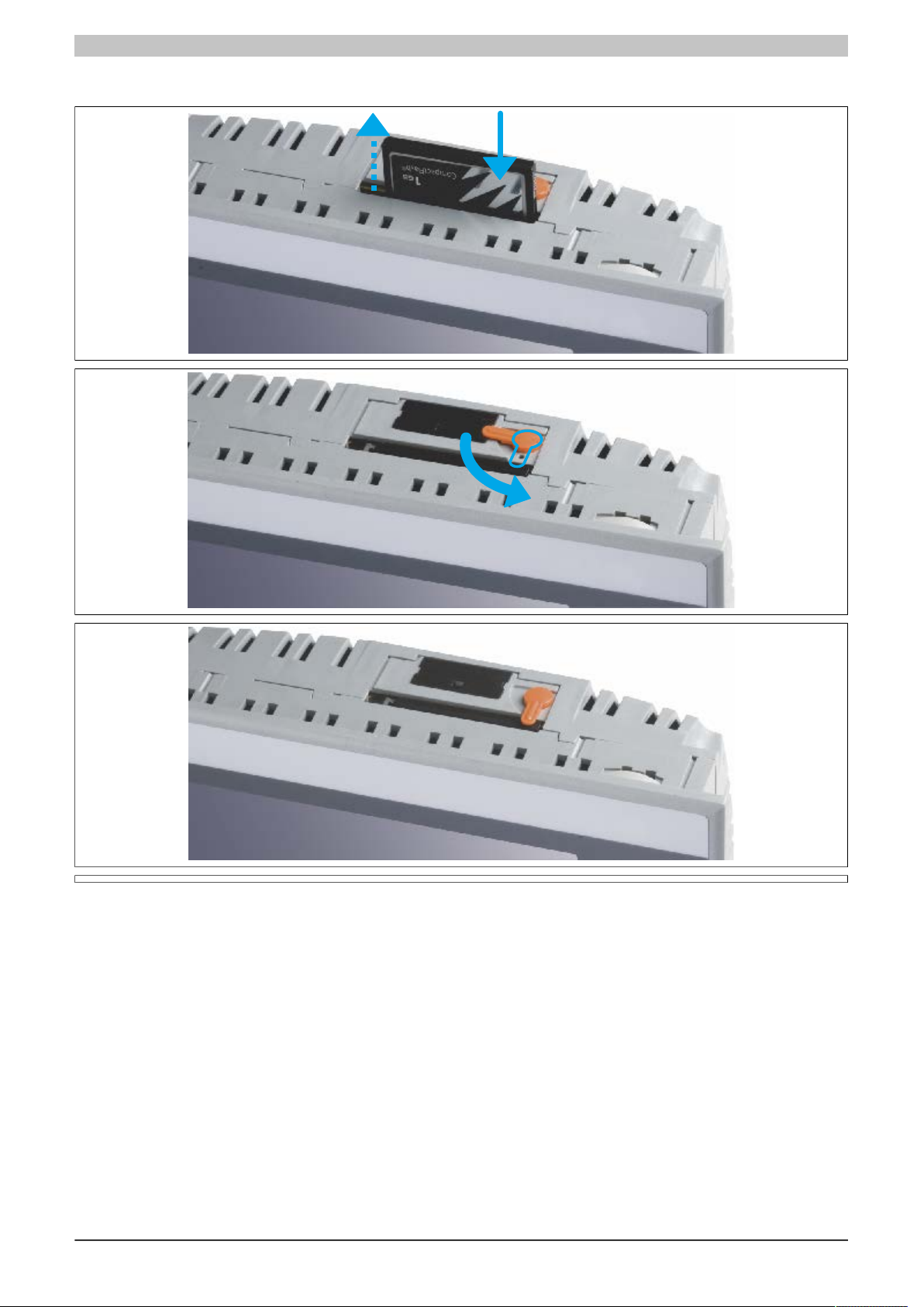
Insert the CompactFlash card by hand (contact side first) into the CompactFlash slot until it is flush with the front
of the device (1). This will push the ejection lever out to the same level (2). The CompactFlash slot is mechanically
designed to prevent the card from being inserted incorrectly. If inserted incorrectly, the CompactFlash card will not
go in all the way and the ejection lever will not extend out. Finally, rotate the safety latch over the CompactFlash
slot (3) to secure the CompactFlash card (4).
26 Data sheetV 1.00 4PP065.0571-B00
Page 27

Maintenance
5.4 Preventing screen burn-in on LCD/TFT displays
Screen burn-in (afterimages, display memory effect, image retention or image sticking) occurs on LCD/TFT displays
if a static image is displayed for a prolonged period of time. This static screen content causes the build-up of
parasitic capacitances within the LCD components that prevent liquid crystal molecules from returning to their
original state. This condition is unpredictable and can depend on the following factors:
•
Type of image displayed
•
Color composition of the image
•
Length of time that the image is displayed
•
Ambient temperature
5.4.1 How can this be avoided?
There is no perfect solution. There are ways to significantly reduce this effect, however:
•
Avoid static images or screen content.
•
Use non-static screensavers when the display is not in use.
•
Change images frequently.
•
Turn off the display when not in use.
Turning off the backlight does not help prevent screen burn-in.
Data sheetV 1.00 4PP065.0571-B00 27
Page 28

Figure index
Figure 1: 4PP065.0571-B00 - Oblique view........................................................................................... 3
Figure 2: 4PP065.0571-B00 - Rear view................................................................................................ 4
Figure 3: 4PP065.0571-X74F - Diagnostic LEDs................................................................................... 6
Figure 4: 4PP065.0571-X74F - ACT/LNK LEDs for the RJ45 port........................................................ 7
Figure 5: 4PP065.0571-X74F - Connection elements............................................................................ 8
Figure 6: 4PP065.0571-X74F - Operating mode and node number switches...................................... 11
Figure 7: 4PP065.0571-B00 - Dimensions........................................................................................... 15
Figure 8: 4PP065.0571-B00 - Cutout installation................................................................................. 16
Figure 9: 4PP065.0571-B00 - Panel overlay design............................................................................ 17
Figure 10: 4PP065.0571-B00 - Slide-in labels........................................................................................18
Figure 11: Power Panel - Mounting orientations.................................................................................... 21
Figure 12: Changing the battery - Removing the battery cover............................................................. 24
Figure 13: Changing the battery - Removing the battery....................................................................... 24
Figure 14: Battery handling..................................................................................................................... 24
Figure 15: Removing the CompactFlash card........................................................................................ 25
28 Data sheetV 1.00 4PP065.0571-B00
Page 29

Table index
Table 1: 4PP065.0571-B00 - Order data.................................................................................................... 5
Table 2: Version information....................................................................................................................... 5
Table 3: 4PP065.0571-X74F – Supported interface modules.................................................................... 5
Table 4: 4PP065.0571-X74F - Diagnostic LEDs up to AR I2.96, D3.01 and A3.06................................... 6
Table 5: 4PP065.0571-X74F - Diagnostic LEDs starting with AR J2.96, E3.01 and B3.06........................7
Table 6: 4PP065.0571-X74F - Status LED blink code............................................................................... 7
Table 7: 4PP065.0571-X74F - ACT/LNK LEDs for the RJ45 port..............................................................7
Table 8: 4PP065.0571-X74F - X2X Link pinout..........................................................................................8
Table 9: 4PP065.0571-X74F - USB interface............................................................................................. 9
Table 10: 4PP065.0571-X74F - Ethernet interface pinout..........................................................................10
Table 11: 4PP065.0571-X74F - Supply voltage pinout...............................................................................10
Table 12: 4PP065.0571-X74F - Operating mode and node number switches........................................... 11
Table 13: 4PP065.0571-B00 - Technical data............................................................................................12
Table 14: Spacing for air circulation - Rear view........................................................................................19
Table 15: Spacing for air circulation - Side view........................................................................................ 20
Table 16: Installing PP65 interface modules in the Power Panel 65..........................................................22
Table 17: Battery status.............................................................................................................................. 23
Data sheetV 1.00 4PP065.0571-B00 29
 Loading...