

Page 1
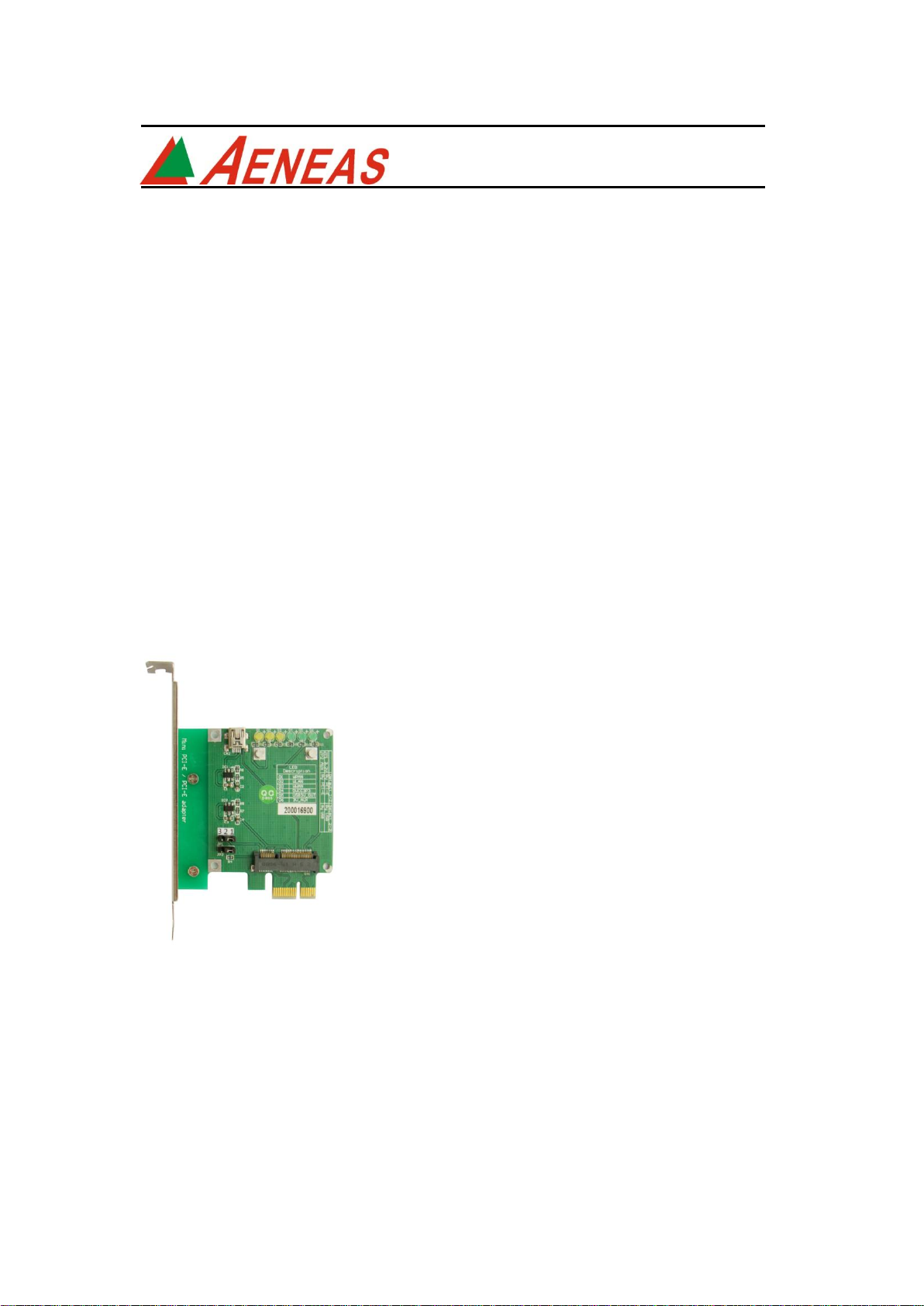
Mini PCI-E to PCI-E Adapter
User’s Manual
Preliminary
Model: MP1
Shanghai Aeneas Electronics
Rm.1104-1106, Building 1 Kerry Everbright City
No.218 Tian Mu W. Rd. Shanghai, PRC
(8621)63547786 TEL
(8621)63545095 FAX
http://www.aeneas.com.cn
FAE2009MP1_01
March 2009
Page 2

Mini PCI-E to PCI-E Adapter User’s Manual
Page 1
CONTENTS
Introduction ............................................................................................................ 2
Interface ................................................................................................................... 2
Features .................................................................................................................. 5
Set up before usage ....................................................................................... 5
System requirement ........................................................................................ 5
Installation procedure..................................................................................... 5
Caution ................................................................................................................... 10
Maintenance ....................................................................................................... 10
FAE2009MP1_01 ©2009 Aeneas Electronics
Page 3
Mini PCI-E to PCI-E Adapter User’s Manual
Page 2
1.0 Introduction
The Mini PCI-E to PCI-E Adapter is designed for desktop PC that converts PCI
Express Mini Card to USB and standard PCI-Express 1x slot.
This adapter allows you to use your existing PCI-E slot or USB port of your
M/B.
It includes mini PCI-E connector and Mini-USB port access styles.
2.0 Interface
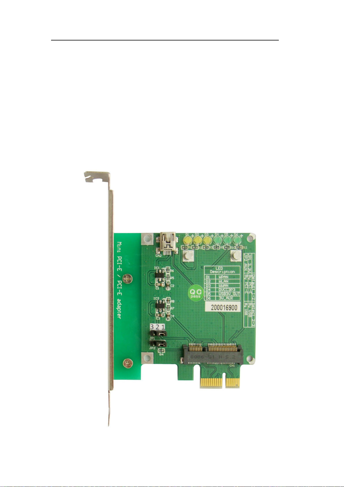
Mini PCI-E to PCI-E Adapter as shown,
Figure-1 Mini PCI-E to PCI-E Adapter (heads)
FAE2009MP1_01 ©2009 Aeneas Electronics
Page 4
Mini PCI-E to PCI-E Adapter User’s Manual
LED
state
W-PAN
W-LAN
W-WAN
OFF
Not powered
Not powered
Not powered
ON
Powered; ready to
transmit or receive
Powered, associated, and
authenticated but not
transmitting or receiving
Powered, associated, and
authenticated but not
transmitting or receiving
Slow Blink
N/A
Powered but not
associated or
Powered but not
associated or
Page 3
Figure Description
FAE2009MP1_01 ©2009 Aeneas Electronics
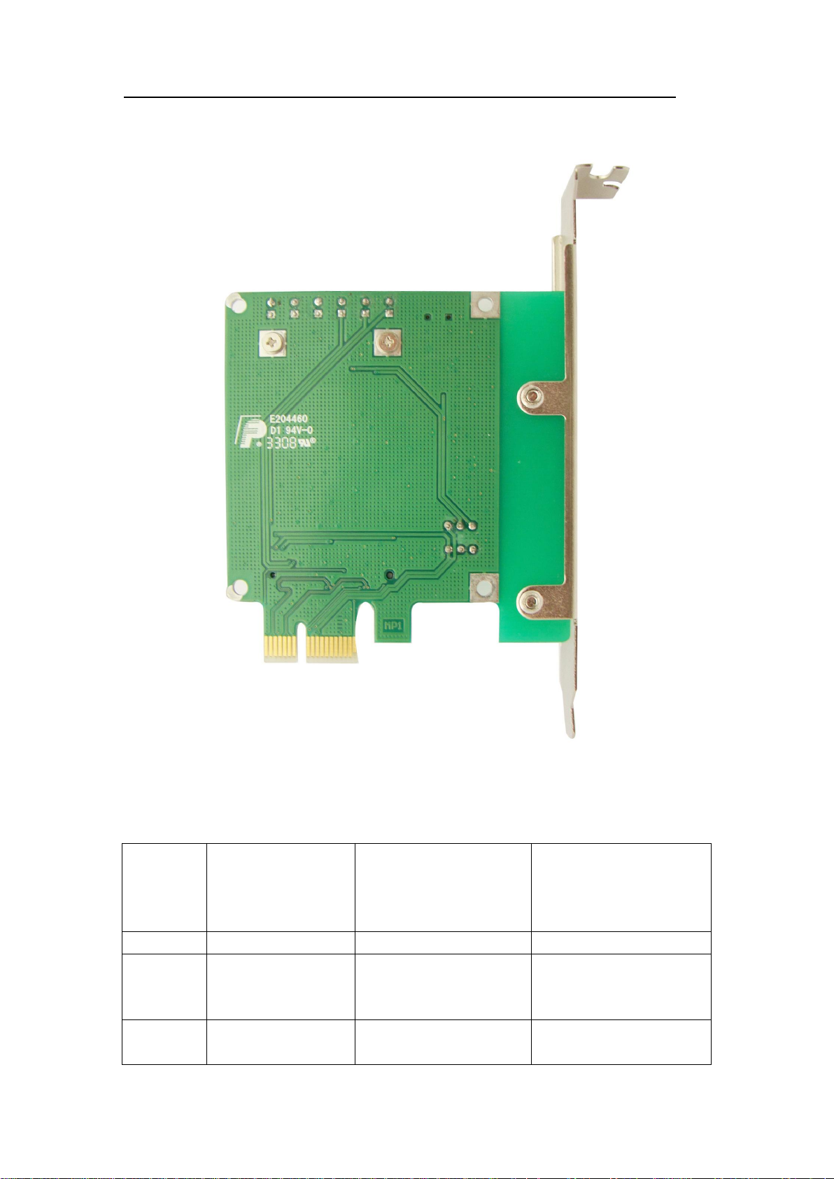
Figure-2 Mini PCI-E to PCI-E Adapter (back)
Page 5

authenticated; searching
authenticated; searching
Intermittent
Blink
Activity proportional
to
transmitting/receiving
speed
Activity proportional to
transmitting/receiving
speed
Activity proportional to
transmitting/receiving
speed
For voice applications,
turning off and on the
intermittent blink based
on the ring pulse cycle
can indicate a ring event
TAB-1 defines the recommended use for LED station for each of the three
wireless classes. (W-PAN/W-LAN/W-WAN)
LED state:
1. D1(W-PAN):
When the user plugs W-PAN (Wireless-Personal Area Network) device such
as Bluetooth, short-distance wireless card into Mini PCI-E interface, this LED
shows different station.
More details, please reference TAB-1.
2. D2(W-LAN):
When the user plugs W-LAN (Wireless-Local Area Network) device such as
wireless LAN mini card into Mini PCI-E interface and it performs, this LED
shows different state.
More details, please reference TAB-1.
3. D3(W-WAN):
When the user plugs W-WAN (Wireless-Wide Area Network) device such as
wireless mini card into mini PCI-E interface, this LED shows different state.
More details, please reference TAB-1.
4. D4: Power Indicator
This LED defines the power status. It will be on only when the PC is power on.
5. D5:
This LED defines the power status. It will be on until mini-USB connector
function performs and powers on. That is, it is not available when the PCI-E
function performs.
6. D6: AUX Power Indicator
This LED defines the AUX power status. When the PCI-E function performs, it
will be on at any occasion that includes power-off and power-down mode.
FAE2009MP1_01 ©2009 Aeneas Electronics
Mini PCI-E to PCI-E Adapter User’s Manual
Page 4
TAB-1
Page 6

Mini PCI-E to PCI-E Adapter User’s Manual
Page 5
3.0 Features
Allows user to test PCI Express Mini modules on the PCI Express slot or USB
port;
Supports two primary system bus interface: PCI Express and USB;
Supports all of mini-Cards such as WLAN, WWLAN, MODEM Mini Card to
desktop PC.
4.0 Set up before usage
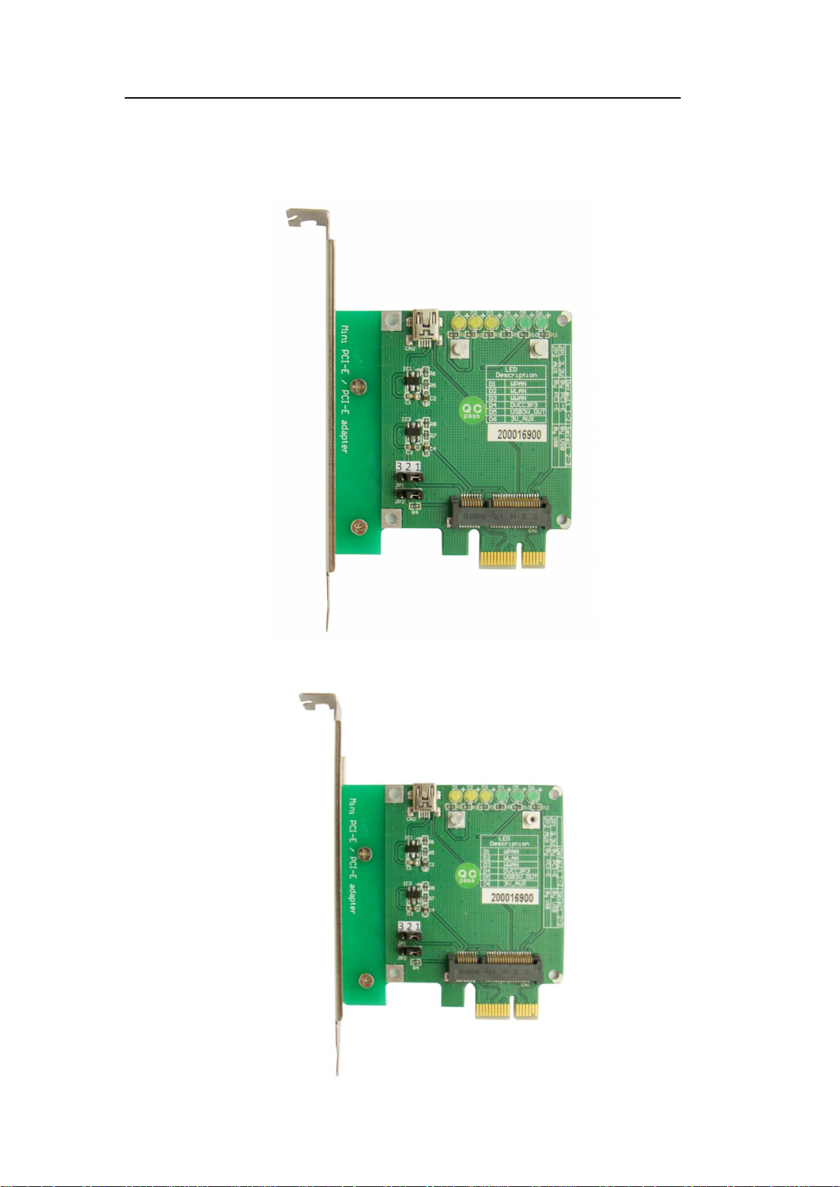
JP1, JP2 default state: 1-2
JP1, JP2 select state: 2-3
This adapter provides PCI-E and Mini-USB two access styles. The user should
set up as below,
1. PCI-E style: set jumper cap on JP1 1-2 , JP2 1-2
2. Mini-USB style: set jumper cap on JP1 2-3, JP2 2-3
5.0 System requirement
PCI-Express 1x slot or USB port
Windows 2000, XP, Vista 32/64
Linux
6.0 Installation procedure
Please check the support style of your wireless mini card and use
the adapter according to the correct installation procedure.
FAE2009MP1_01 ©2009 Aeneas Electronics
Page 7
Mini PCI-E to PCI-E Adapter User’s Manual
Page 6
PCI-E access style
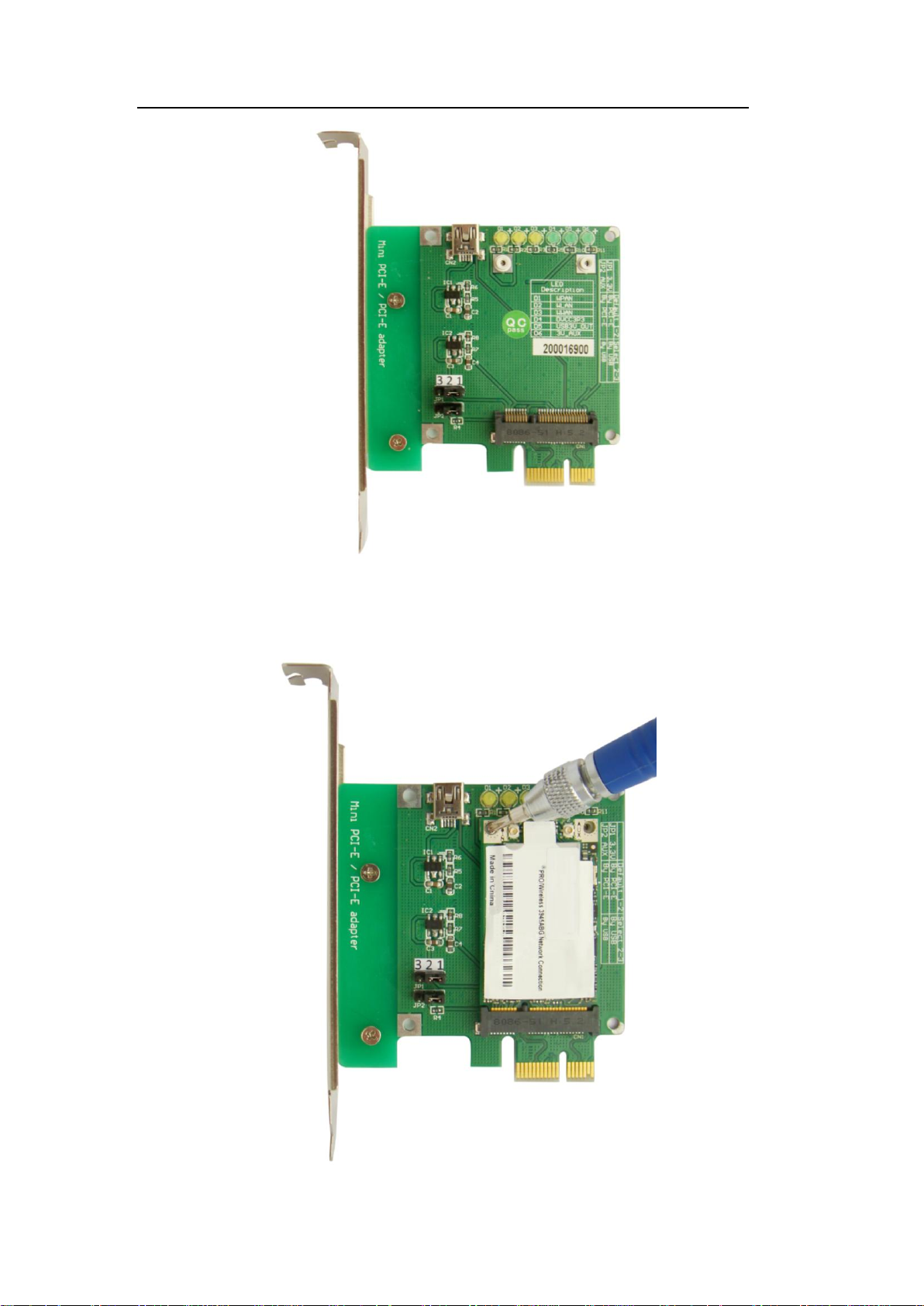
1) Please check the Jumper cap on JP1 and JP2 firstly, because the incorrect
set up will lead to the adapter not work normally.
2) Remove the caps on screws,
FAE2009MP1_01 ©2009 Aeneas Electronics
Page 8
Mini PCI-E to PCI-E Adapter User’s Manual
Page 7
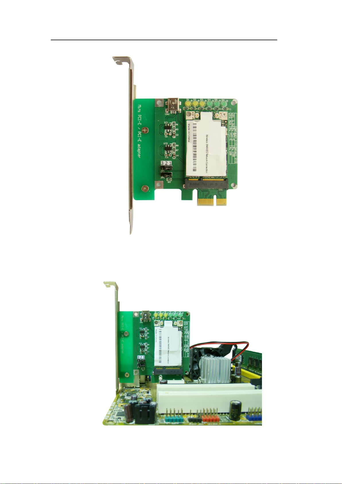
3) Plug mini card device such as wireless LAN card into mini PCI-E connector,
the other side should be fixed by two screws.
FAE2009MP1_01 ©2009 Aeneas Electronics
Page 9
Mini PCI-E to PCI-E Adapter User’s Manual
Page 8
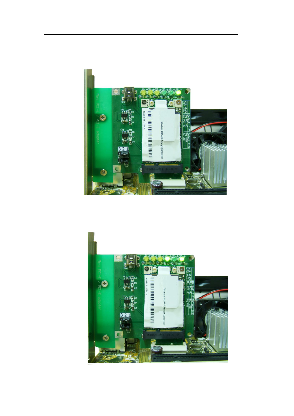
4) Before the user plugs PCI-E connector into PC M/B, please ensure cut off
the PC power firstly, then continue plug-in. Do not deal with it when
energized, incorrect approach will lead to product damage.
FAE2009MP1_01 ©2009 Aeneas Electronics
Page 10
Mini PCI-E to PCI-E Adapter User’s Manual
Page 9
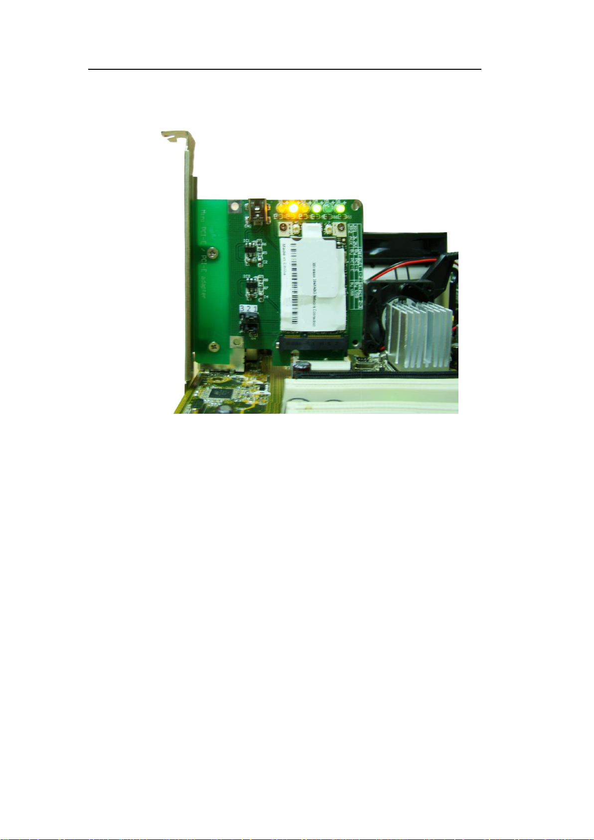
5) When the user plugs Mini PCI-E to PCI-E Adapter into PCI-E slot, LED D6
is on at any occasion.
6) When PCI-E function performs, LED D6 and D4 will be on at the same
time.
FAE2009MP1_01 ©2009 Aeneas Electronics
Page 11
Mini PCI-E to PCI-E Adapter User’s Manual
Page 10
7) When the wireless LAN card performs, LED D2 will show different
state.(reference TAB-1)
8) Power off the PC, then remove Mini PCI-E to PCI-E Adapter and Wireless
LAN card.
Mini USB access style
1) Please check the Jumper cap on JP2 and JP3 firstly, because the incorrect
set up will lead to the adapter not work normally.
2) Then, plug the wireless mini card into the Mini-PCIE connector, the other
side should be fixed by two screws.
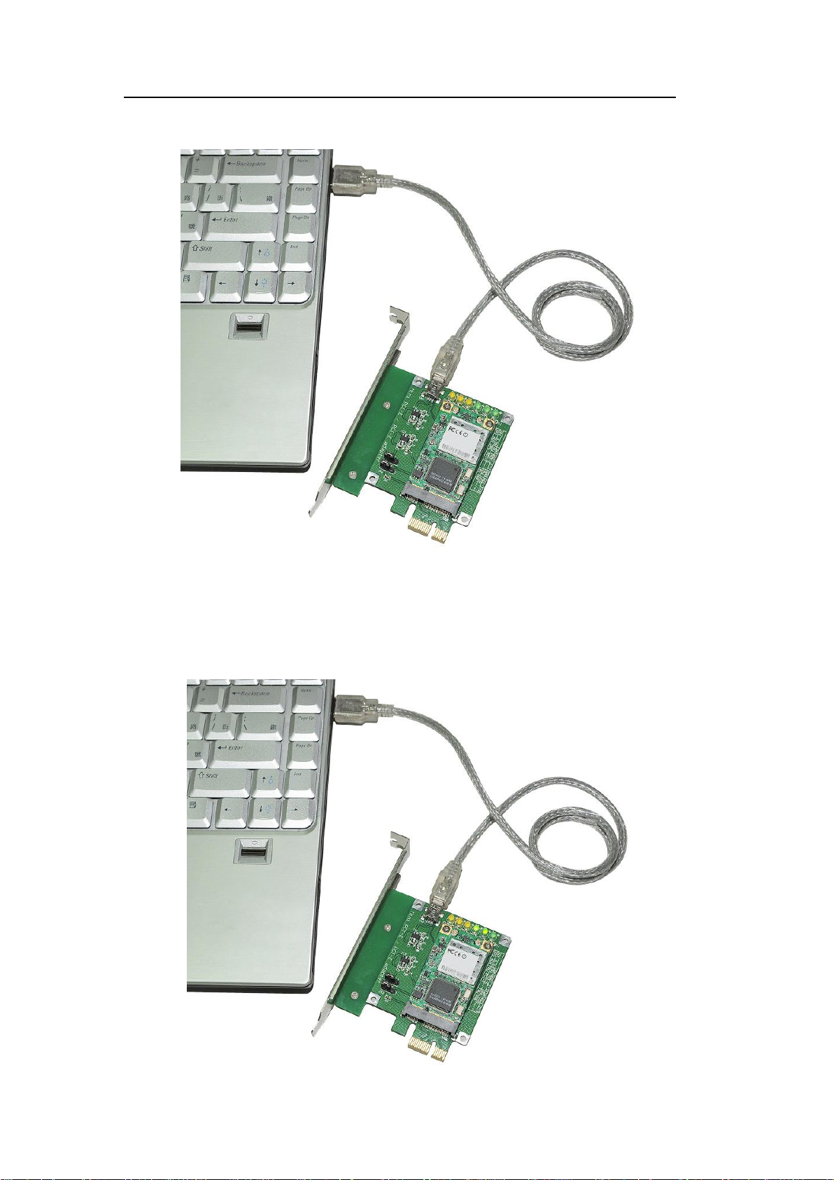
3) Plug one side of cable line into Mini-USB port of this adapter, the other into
PC USB slot.
FAE2009MP1_01 ©2009 Aeneas Electronics
Page 12
Mini PCI-E to PCI-E Adapter User’s Manual
4) Now, before power on the PC, all LEDs are off state.
Page 11
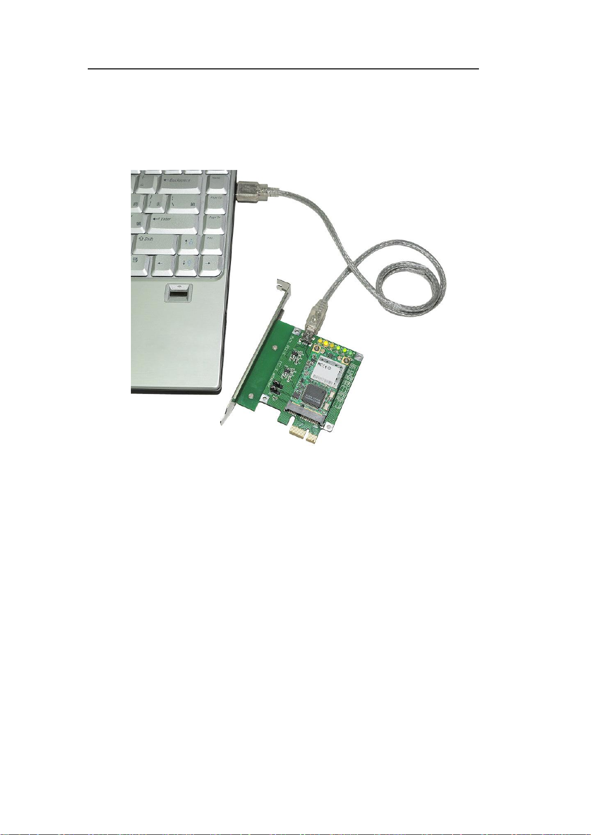
5) When the user powers on the PC, LED D4 and D5 will be on before driver
installation.
FAE2009MP1_01 ©2009 Aeneas Electronics
Page 13
Mini PCI-E to PCI-E Adapter User’s Manual
Page 12
6) After the driver installation and unavailable Net, D4 and D5 will be on and
D2 will flicker per 3 sec
7) Finally, when net available, D4 and D5 will be on and D2 flickers according
to transmitting data.
USB cable line supports plug and play function, it is unnecessary to deal with it
on turn-off mode.
Other installation procedure may reference PCI-E access style.
7.0 Caution
Before PCI-E mode performs, please cut off the PC power, also as the same to
the remove. The incorrect action will lead to product damage.
The adapter provides mini USB and PCI-E access styles. Please choose the fit
style according to the working mode of mini card.
All products specifications are subject to change without notice.
Aeneas reserves the right to modify the products in its line during the course of
the year.
FAE2009MP1_01 ©2009 Aeneas Electronics
Page 14

Mini PCI-E to PCI-E Adapter User’s Manual
Page 13
8.0 Maintenance
There is no guarantee while PC power is on and MP1 is been removing.
Please contact the distributer for more details.
FAE2009MP1_01 ©2009 Aeneas Electronics
 Loading...