

Boyertown Regal Oil Furnace Nrg Max User Manual
Regal Oil Fired Furnace
Installation and Operation Instructions
Manual
Keep these instructions with the furnace at all times
for future reference
Boyertown Furnace Co.
PO Box 100
Boyertown, PA 19512
610-369-1450
www.boyertownfurnace.com 7-1-14
g
g
Be Aware of Hazard Definitions
Danger
Warnin
Caution
Notice
Denotes presence of a hazard which, if ignored, will result in severe personal injury,
death or property damage
Denotes presence of a hazard which, if ignored could result in severe personal injury,
death or substantial property damage.
Denotes the presence of a hazard, which if ignored, could result in minor personal injury
or property damage
Intended to bring attention to information, but not related to personal injury or property
damage.
Danger
This equipment must be installed, adjusted and started only by a qualified service agency – an
individual or agency, licensed and experienced with all codes and ordinances, and who is responsible for the
installation and adjustment of the equipment. THE INSTALLATION OF THE EQUIPMENT SHALL BE IN
ACCORDANCE WITH THE REGULATION OF AUTHORITIES HAVING JURIDICTION AND OR NFPA
31.
Read all instructions before proceeding. Follow all instructions completely. Failure to follow these
instructions could result in equipment malfunction causing severe personal injury, death or substantial property
Warnin
damage.
DO NOT TAMPER WITH THE UNIT OR CONTROLS – CALL YOUR SERVICEMAN. The manufacturer
will not be liable for any damage resulting from changes made in the field to the furnace or its components or
from improper installation. Failure to comply could result in severe personal injury, death, or substantial
property damage.
DO NOT USE WITH OILS HEAVIER THAN NO. 2. NEVER USE GASOLINE, CRANKCASE OIL, OR
ANY OIL CONTAINING GASOLINE. Your oil fired furnace is designed to burn No. 1 and No. 2 heating oil
only.
DO NOT START THE BURNER UNLESS THE BLOWER ACCESS DOOR IS SECURED IN PLACE.
Do not store gasoline or other flammable vapors and liquids in the vicinity of this or any other appliance.
The area around the furnace should be kept free and clear of combustible materials.
NEVER BURN GARBAGE OR REFUSE IN THE HEATING SYSTEM, AND NEVER LEAVE PAPER OR
RAGS AROUND THE UNIT.
Never try to ignite oil by tossing burning papers or other material into your furnace.
DO NOT ATTEMPT TO START THE BURNER WHEN EXCESS OIL HAS ACCUMULATED OR THE
FURNACE IS FULL OF VAPORS OR WHEN THE CHAMBER IS VERY HOT
Do not use the furnace as a construction heater.
Do not operate furnace if the heat exchanger is damaged. Toxic flue products could enter air stream.
Do not jumper, attempt to bypass or override any of the safety limit controls.
Do not use this furnace if any part has been under water. Immediately call a qualified service technician to
inspect the furnace and replace any part of the furnace, control system or burner that has been under water.
Do not operate furnace if temperature rise through the heat exchanger exceeds that which is listed on the
Ratings Label (Typically75
Do not operate furnace without return air properly sized or ducted.
NOTICE
Concealed Damage- If you discover damage to the burner, furnace or controls during
º
F).
unpacking, notify the carrier at once and file the appropriate claim. When calling or writing about the
furnace please have the following information available: the furnace model number and serial number
which is located on the upper portion of the front of the unit. Record the model and serial number for
future reference in the space provided in this manual.
2
.

TABLE OF CONTENTS PAGE NO.
FURNACE SPECIFICATIONS 4
INSTALLATION CLEARANCES
Standard Clearances
Reduced Clearances
DUCT WORK
Sizing
Blower Specifications
Filter Racks
Multiple Furnace Installation
ECM MOTORS
Operating Modes
Air Flow Selection
Motor Connections
PSC MOTORS
Air Flow Selection
VENTING
Chimney Venting
Chimney Relining
Chimney Connector
Power Venting
Vent Dampers
5
7
10
12
12
VENTILATION AND COMBUSTION AIR 15
BURNER INSTALLATION 15
WIRING
Power
Thermostat
17
OIL TANK AND PIPING 23
START UP
24
Start Up Equipment
Burner Adjustments
OPERATING AND MAINTENANCE
26
Cleaning the Furnace
Oil Burner
Blowers – Direct Drive
Vent System
Fuel Oil System
Filters
PARTS BREAKDOWN LISTS 28
TROUBLE SHOOTING GUIDE 31
WARRANTY 32
INSTALLATION AND SERVICE CHECKLIST 33
WARRANTY REGISTRATION 34
3
1000
175,000
140,000
1.25 80B
6"
1.00 80B
1.25 60SS
82.3%
5
100-10T
2283
3/4 Hp 4 sp
16x25
2130
1901
N/R
2007
1832
N/R
N/R
347
38
56 1/2
25 1/2
52 5/8
12 3/4
15
23 3/8
23 3/4
23 5/8
REH
REH750
1000
REL
140,000
120,000
105,000
85,000
175,000
140,000
115,000
1.00 80B
95,000
.85 8 0 B
85,000
.75 80B
70,000
.60 80A
140,000
1.25 80B
115,000
1.00 80B
6"
.85 80B
1.00 60SS
6"
.65 6 0 A
.85 7 0 A
6"
.60 60A
.75 70A
6"
.50 60A
.60 70A
6"
1.00 80B
1.25 60SS
6"
.85 80B
1.00 60SS
85.0%
85.0%
85.4%
85.9%
84.2%
85.0%
16x25
16x25
16x25
16x25
(2 )1 6x 2 0
(2)16x20
100-10T
100-10T
100-10T
100-10T
100-10T
100-10T
2283
3/4 Hp 4 sp
1745
3/4 Hp 4 sp
1745
3/4 Hp 4 sp
1745
3/4 Hp 4 sp
2466
3/4 Hp 4 sp
2466
3/4 H p 4 sp
2130
1901
1550
1376
1550
1376
1550
1376
2150
1839
2150
1839
1717
2007
1250
1480
1250
1480
1250
1480
N/R
2072
1600
2072
1832
1644
N/R
1343
1343
1175
1343
1175
N/R
1859
1859
1610
5
1501
N/R
3 1/2
N/R
3 1/2
1043
3 1/2
5
N/R
5
N/R
347
298
298
298
362
362
56 1/2
53 5/8
53 5/8
53 5/8
46
46
38
25 1/2
52 5/8
12 3/4
22 1/4
33 1/8
49 1/8
11 1/8
22 1/4
33 1/8
49 1/8
11 1/8
22 1/4
33 1/8
49 1/8
11 1/8
25 1/8
53 5/8
38 1/2
21 1/2
25 1/8
53 5/8
38 1/2
12 1/2
15
23 3/8
23 3/4
23 5/8
15
19 3/4
20 1/2
23 5/8
15
19 3/4
20 1/2
23 5/8
15
19 3/4
20 1/2
23 5/8
21 1/2
22 7/8
22 7/8
13 5/8
21 1/2
22 7/8
22 7/8
13 5/8
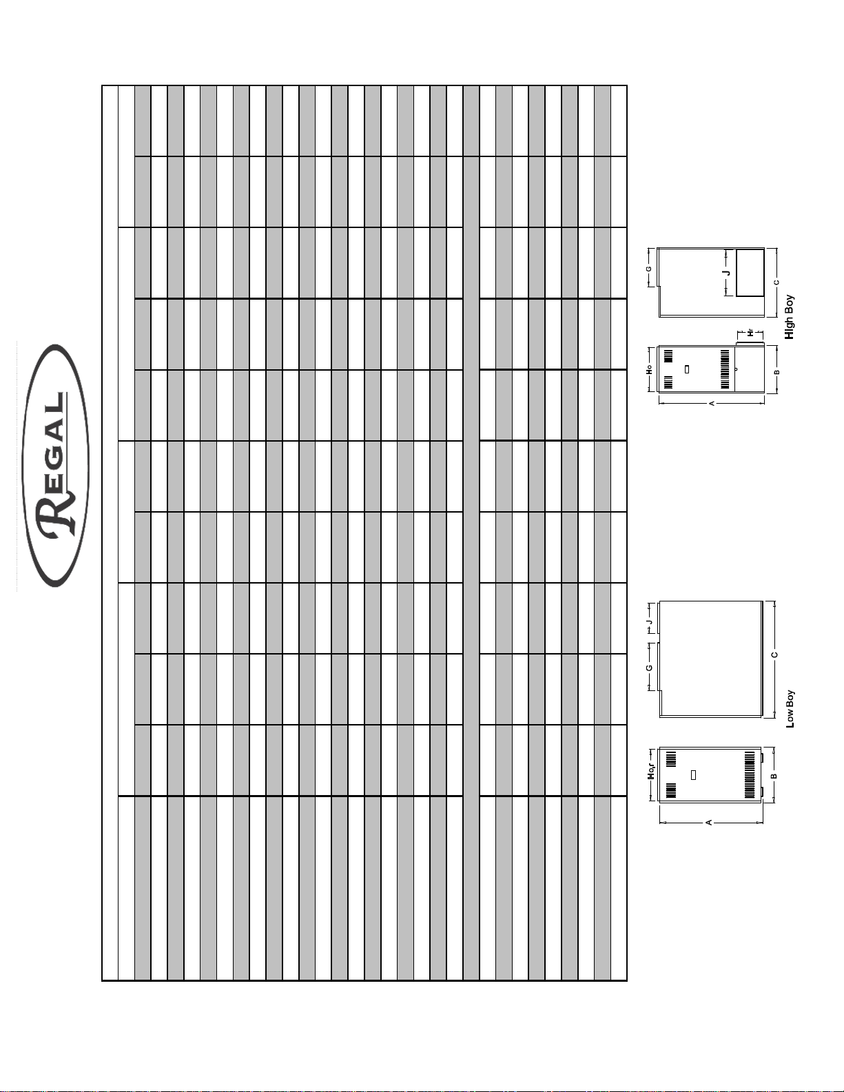
Regal Specifications
RE L750
Model
120,000
105,00
85,000
BTU/Hr Input
95,000
.85 80B
85,000
.75 80B
70,000
.60 8 0 A
BTU/Hr Output
Nozzle Beckett AFG @ 100PSI
6"
.65 60A
.85 70A
6"
.60 60A
.75 70A
6"
.50 6 0 A
.60 7 0 A
Nozzle R iello 40 Series @ 150P SI
N o z z le C a r lin E Z - 1 @ 1 0 0 P S I
Flue Size
85.0%
84.4%
85.9%
AFU E S easonal Efficiency
(2)1 6 x 20
(2)16x20
(2)1 6 x2 0
Filter Size (inches)
100-10T
100-10T
100-10T
Blower S ize
1903
3/4 H p 4 sp
1903
3/4 H p 4 sp
1903
3/4 H p 4 sp
Blower M otor
C F M @ 0.2 "W C Hig h
1711
1711
1711
Med High
1547
1399
1547
1399
1547
1399
Low
M ed Low
1661
1661
1661
C F M @ 0.5 "W C Hig h
1485
1485
1485
Med High
N/R
1355
1355
1227
1355
1227
Low
M ed Low
4
4
4
Cooling C apacity (Tons)
323
323
323
Shipping W eight (lbs)
Dimensions (Inches)
40
20 1/4
47 1/2
31 1/4
10 1/8
17 1/2
40
20 1/4
47 1/2
31 1/4
10 1/8
17 1/2
40
20 1/4
47 1/2
31 1/4
10 1/8
17 1/2
C a b in et H eig h t A
C a b in et W id th B
C a b in et D ep th C
Center Line Flue to Floor D
Center Line Flue to Side E
W arm A ir Supply D epth G
14
18 1/4
18 1/4
14
18 1/4
18 1/4
14
18 1/4
18 1/4
W arm A ir Supply Width H o
R e tu rn A ir W idth Hr
R e tu rn A ir Dep th J
4
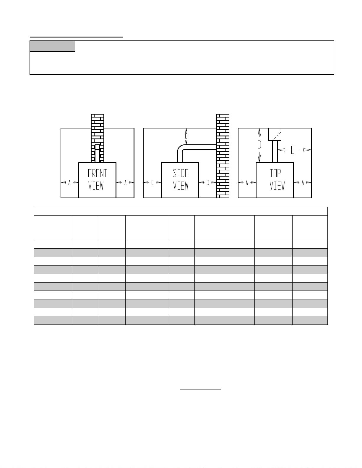
Installation Clearances
Furnaces in rooms shall be installed with the clearances from combustible materials not
WARNING
less than indicated in Table 1. Combustible materials are those made of or surfaced with wood,
compressed paper, plant fibers, plastics, or other material that will ignite and burn, whether flame proofed
or not, or whether plastered or not.
Place the furnace near the center of the supply and return ducts and as close to the chimney connector
as possible. Provide a solid brick or 2” thick minimum concrete pad if the furnace mounting area is
not level or if the floor can become flooded.
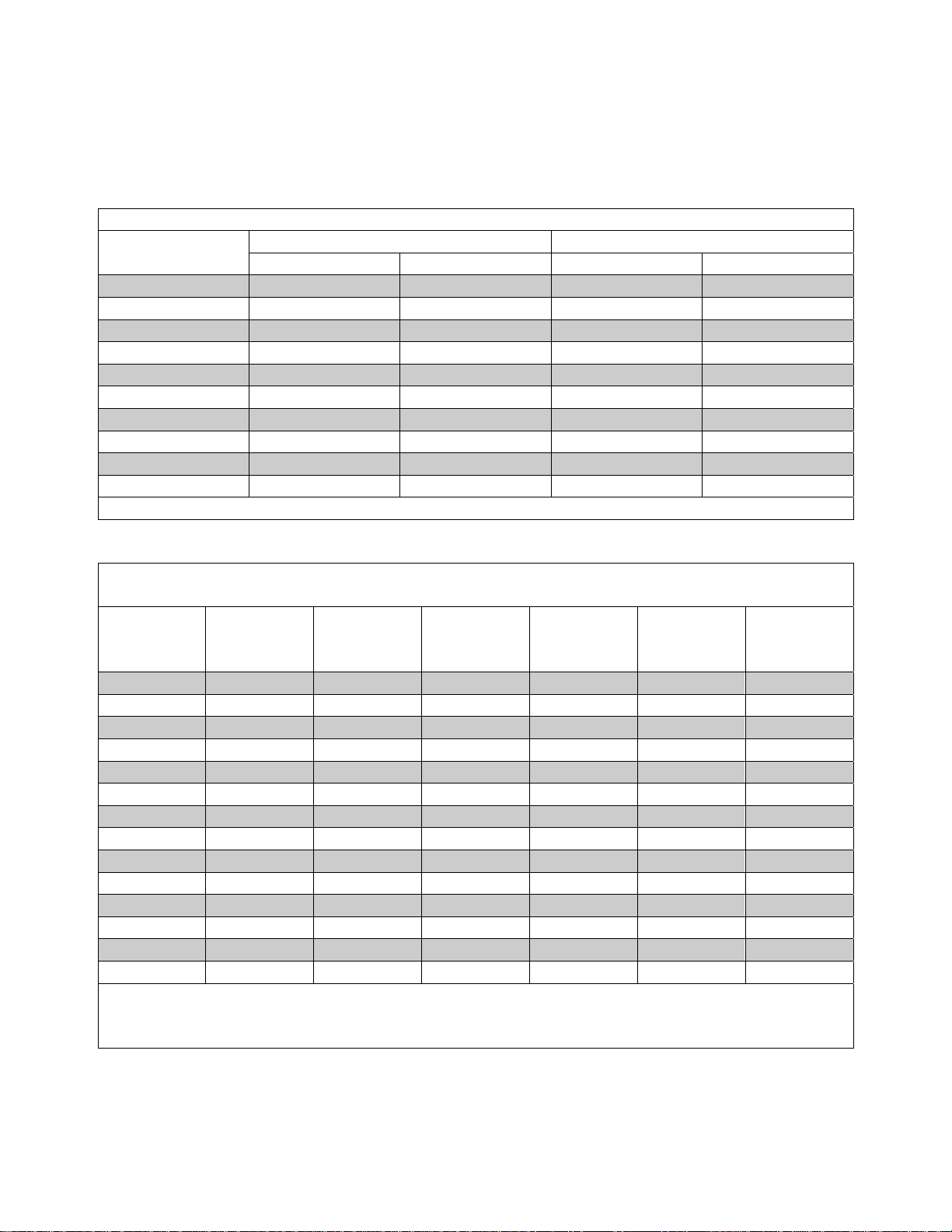
Table 1 Standard Installation Clearances
MODEL
Sides
“A”
Top
“B”
Front
“C”
Rear
“D”
Flooring Chimney
Connector
“E”
Plenum
Top &
Sides
REH600 2” 2” Alcove-24” 2” Combustible 18” 2”
REL600 2” 2” Alcove-24” 2” Noncombustible 18” 2”
REH750 2” 2” Alcove-24” 2” Combustible 18” 2”
REL750 2” 2” Alcove-24” 2” Noncombustible 18” 2”
REH850 2” 2” Alcove-24” 2” Combustible 18” 2”
REL850 2” 2” Alcove-24” 2” Noncombustible 18” 2”
REH1000 2” 2” Alcove-24” 2” Combustible 18” 2”
REL1000 2” 2” Alcove-24” 2” Noncombustible 18” 2”
REH1250 2” 2” Alcove-24” 2” Combustible 18” 2”
REL1250 2” 2” Alcove-24” 2” Noncombustible 18” 2”
Lowboy furnaces not listed for combustible floor may be placed on combustible floors although not
listed for such installation, provided the floor under the furnace is protected in accordance with the
requirements of accepted building code practice and NFPA 31. The furnaces shall be permitted to be
placed on combustible flooring protected by 4” hollow block placed with ends unsealed and joints
matching in such a fashion as to permit free circulation of air from side to side through the masonry.
The block must be covered with sheet metal not less than 24 gauge.
Furnaces are permitted to be installed in rooms, but not closets, with lesser clearances to combustible
material, provided the combustible material is protected as described in Table 2 and NFPA 31. In no
case shall the clearance be such as to interfere with the requirements for combustion air, draft
regulators and accessibility.
5
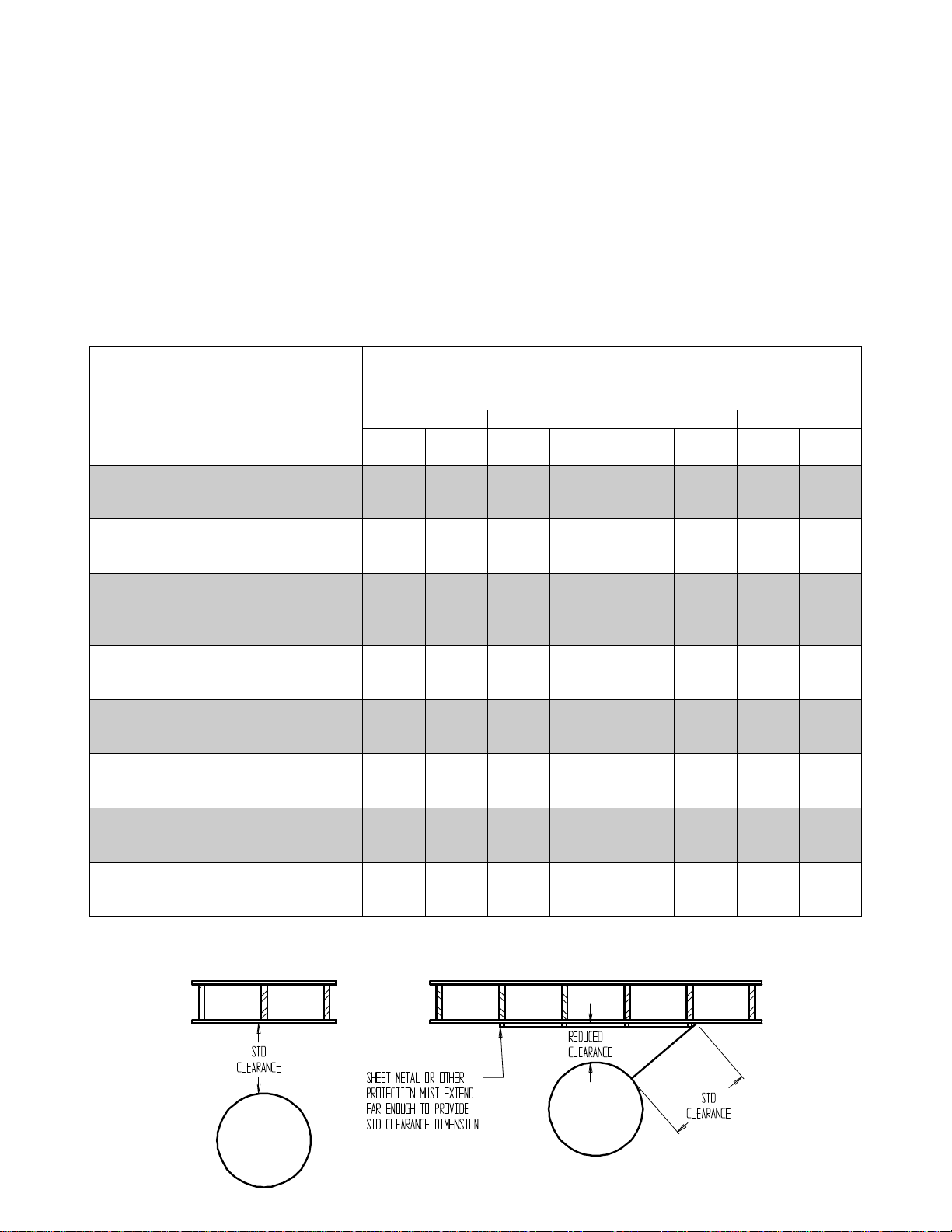
All clearances shall be measured from the outer surface of the combustible material to the nearest
point on the surface of the appliance or chimney connector, disregarding any intervening protection
applied to the combustible material.
Spacers and ties are to be of noncombustible material. No spacer or tie shall be used directly opposite
an appliance or chimney connector.
With all clearance reduction systems using ventilated air space there shall be at least 1” clearance
between the reduction systems using ventilated air space.
Mineral wool batts, blanket or board shall have a minimum density of 8lb/ft3 and a minimum melting
temperature of 15000F.
Insulation material used as part of a clearance reduction system shall have a thermal conductivity of
1.0(Btu/In)/ (Ft2/Hr/0F).
Table 2 Allowable Clearances with Specified Protection
Type of protection applied to and
covering all surfaces within the distance
specified as the required clearance with
no protection
Where the Specified Clearance with No Protection from the Appliance or
Chimney Connector
18” 12” 9” 6”
Above Rear &
Sides
Above Rear &
Sides
Above Rear &
Sides
Above Rear &
Sides
3½” thick masonry wall without
ventilated air space
½” insulation board over 1” glass fiber
or mineral wool batts
24 gauge sheet metal over 1” glass fiber
or mineral wool batts reinforced with
wire on rear face with ventilated air
space
3½” thick masonry wall with ventilated
air space
24 gauge sheet metal with ventilated air
space
½” insulation board with ventilated air
space
24 gauge sheet metal with ventilated air
space over 24 gauge sheet metal with
ventilated air space
1” glass fiber or mineral wool batts
sandwiched between 2 sheets 24 gauge
sheet metal with ventilated air space
N/A 12” N/A 9” N/A 6” N/A 5”
12” 9” 9” 6” 6” 5” 4” 3”
9” 6” 6” 4” 5’ 3” 3” 3”
N/A 6” N/A 6” N/A 6” N/A 6”
9” 6” 6” 4” 5” 3” 3” 2”
9” 6” 6” 4” 5” 3” 3” 3”
9” 6” 6” 4” 5” 3” 3” 3”
6” 6” 6” 4” 5” 3” 3” 3”
If the furnace is to be installed in a residential garage, the furnace must be a minimum of 18” above
the garage floor and located so it cannot be damaged by a moving vehicle.
6

Duct Work
NOTICE
The duct system should follow the design standards of Air Conditioning Contractors of
America (ACCA) or ASHRAE. The duct system should be sized for the maximum CFM capabilities
of the furnace being installed.
All trunk lines, take-offs, registers and grill free areas must be figured when determining the air
handling capacity of a duct system. By utilizing the Tables 3 through 5, one can obtain the necessary
duct system size. Use a supplier's catalog for proper sizing of outlet and return air registers to insure
that the register will meet the CFM requirements of the run to which it is connected. Do not exceed
the recommended flow rate. The pressure drop for each should not exceed 0.05 inch water column.
The return air ducts should equal the warm air duct system in CFM capacities. Avoid locating a return
air duct in rooms that may contain undue odors. Use only a return air filter mounted to or integral to
the furnace. Do not add additonal filters unless the duct system is sized to allow for the additional
pressure drop. An open return in a basement does not meet the requirements of return air.
Instruct the homeowner not to block any returns.
Always check the size of existing ducts, particularly if you are adding air conditioning. The pressure
drop through the cooling evaporator coil reduces available air flow. If the ducts are too small the
system may not work satisfactorily or be noisy on either heat or cooling.
If the furnace is used in connection with summer air conditioning, the furnace should be installed
parallel with or on the upstream side of the evaporator coil to avoid condensation in the furnace heat
exchanger. The evaporator coil must be installed at least 6” above the heat exchanger for proper air
flow. Distances less than 6” will result in decreased air flow. In all cases refer to the manufacturers
data for static pressure losses to ensure the total system static pressure does not exceed 0.5” WC. If
the cooling unit is installed with a parallel flow arrangement, dampers or other means used to control
flow of air should be provided to prevent chilled air from entering the furnace. If such a damper is
manually operated, it must be equipped with a means to prevent operation of either unit, unless the
damper is in the full heat or cool position.
NOTE: When a return register is located in the same room as the furnace, the register must be at least
20 feet away from the furnace.
To obtain proper CFM on a direct drive unit the blower motor speed may need to be changed
depending upon the size of the air conditioning system installed and the static resistance of the duct
system. See blower specifications for air conditioning CFM's at a .5 static.
Determining Air Flow CFM
The temperature rise through the furnace should not exceed the rated temperature rise as listed
on the Rating Label (Typically750F) and should be at least 550F for comfort.
The sensible heat temperature change for cooling would be approximately 300F. Actual temperature
change will be approximately 20
0
F due to the humidity in the air.
To calculate the sensible heat change or temperature rise the following formula applies
∆T = (Btuh – Output)/(1.1 x CFM)
To calculate the air flow when you know the temperature rise the following formula applies
CFM = (Btuh – Output)/ (1.1 x ∆T)
An estimate of air flow can be achieved by the following rules of thumb:
Heating: 1300 CFM per 100,000 Btuh output
7
Cooling: 400 CFM per ton of air conditioning
Determine the required air flow for the system based on both heating and cooling requirements. Use
the larger of either for duct design.
Table 3 lists the maximum recommended air velocities for ducts. Velocities greater than those as
listed may result in objectionable air noise in the ducts.
Table 3 Recommended Maximum Duct Velocities, Feet Per Minute (FPM)
Application
Supply Return Supply Return
Main Ducts* Branch Ducts
Apartments 900 700 600 600
Auditoriums 1200 1000 1000 800
Banks 2000 1500 1600 1200
Hotel Rooms 1500 1300 1200 1000
Libraries 2000 1500 1600 1200
Meeting Rooms 2000 1500 1600 1200
Offices 2000 1500 1600 1200
Residences 900 700 600 600
Restaurants 2000 1500 1600 1200
Retail Stores 2000 1500 1600 1200
*When sound control is critical use branch duct velocities
Table 4 Duct Area Required at Listed Flow Conditions
CFM Area
Sq. In.
600FPM
Area
Sq. In.
800FPM
Area
Sq. In.
1000FPM
Area
Sq. In.
1200FPM
Area
Sq. In.
1600FPM
Area
Sq. In.
2000FPM
50 12
100 24 18 14 12
150 36 27 22 18 14
200 48 36 29 24 18 14
250 60 45 36 30 23 18
300 72 54 43 36 27 22
400 96 72 58 48 36 29
500 120 90 72 60 45 36
750 180 135 108 90 68 54
1000 240 180 144 120 90 72
1250 300 225 180 150 113 90
1500 360 270 216 180 135 108
1750 420 315 252 210 158 126
2000 480 360 288 240 180 144
Note: For Systems not over 100 feet equivalent length. Do not apply this table to duct systems
which exceed 100 equivalent feet in length. For longer systems refer to ACCA Manual D.
Incorrectly sized ducts can result in unsafe or uncomfortable operation.
8
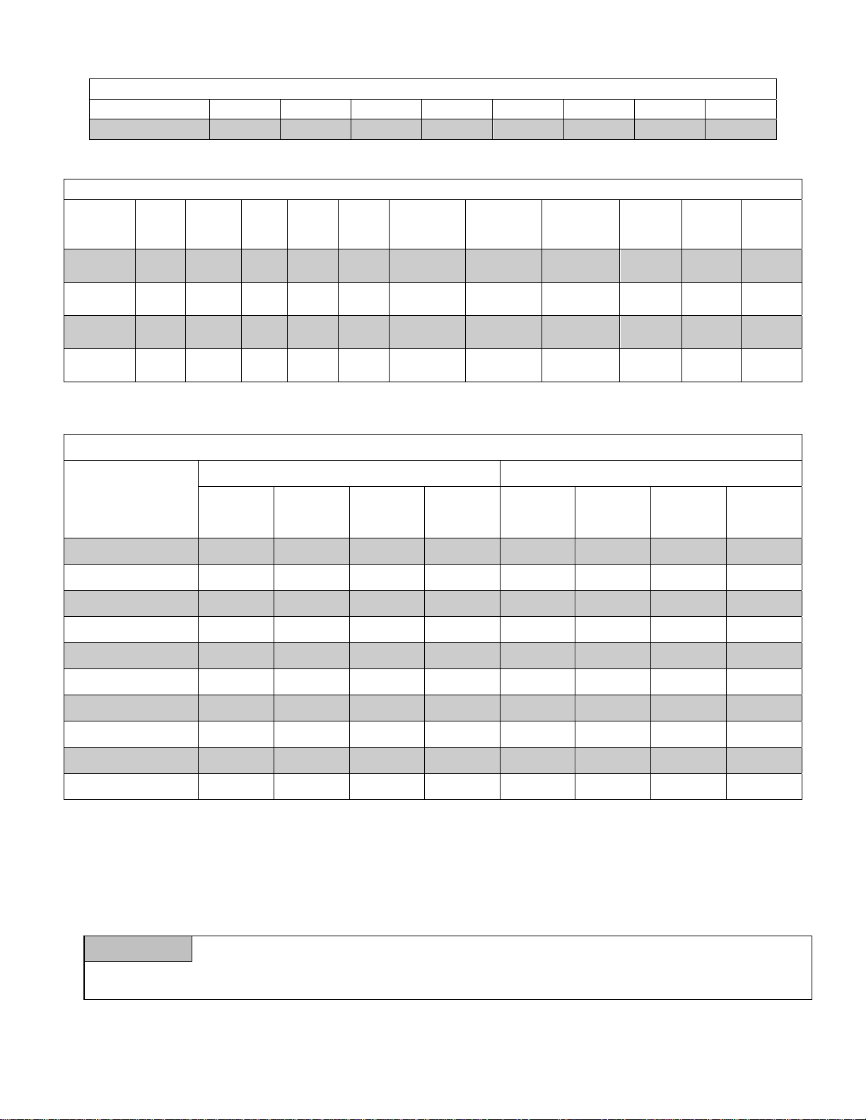
Table 5 Round Duct Equivalent Area
Nominal Size 4 5 6 7 8 9 10 12
Area in.2 12.5 19.6 28.3 38.5 50.3 63.6 78.5 113.1
Table 7 Direct Drive Blower Specifications
Model HP Speeds RPM Volts Full
Load
Amp.
REL750 3/4 4 1075 115 9.2 15 CCW 100-10T Hi
REL1000 3/4 4 1075 115 9.2 15 CCW 100-10T Hi
REH 750 3/4 4 1075 115 9.2 15 CCW 100-10T Hi
REH1000 3/4 4 1075 115 9.2 15 CCW 100-10T Hi
Capacitor
370 volt
mfd
Rotation Blower
Model
Blower
Speed
AC
Blower
Speed
Change
Med
Low
Med
Hi
Med
Hi
Med
Hi
Table 8 Direct Drive Blower Performance
0.2 In. W.C. Static Pressure 0.5 In. W.C. Static Pressure
Blower
Speed
Heat
Low
Med
Low
Low
Med
Low
High
REL-600 1903 1711 1547 1399 1661 1485 1355 1227
REL-750 1903 1711 1547 1399 1661 1485 1355 1227
REL-850 1903 1711 1547 1399 1661 1485 1355 N/R
REL-1000 2466 2150 1839 1600 2072 1859 1610 N/R
REL-1250 2466 2150 1839 N/R 2072 1859 N/R N/R
REH-600 1745 1550 1376 1250 1480 1343 1175 1043
REH-750 1745 1550 1376 1250 1480 1343 1175 N/R
REH-850 1745 1550 1376 1250 1480 1343 N/R N/R
REH-1000 2283 2130 1901 1717 2007 1832 1644 1501
REH-1250 2283 2130 1901 N/R 2007 1832 N/R N/R
Med.
High
Med. Low Low High
Med.
High
Med. Low Low
MULTIPLE FURNACES IN COMMON DUCT WORK
Multiple furnaces connected to common duct work, either supply, return, or both supply and return
must be wired so that all furnace blower motors are energized at the same time.
Failure to turn all blowers on at the same time can cause a reversal of air flow in those
WARNING
units where the blower motor is not operating. This reversal of air flow can cause premature blower,
blower motor, wiring and or heat exchanger failure.
Please consult the factory for specific wiring instructions for your application.
9

ECM MOTOR OPERATING MODES
Introduction
The ECM 5.0 motor is a variable speed, high effiency motor which has the ability to produce constant
air flow within a system, independent of static pressure. It achieves constant air flow by adjusting
speed and torque to account for changes in system static pressure. The GE ECM uses a proprietary
mathmatical algorithim to model air moving systems driven by forward curved blower wheels.
Operating Modes
The ECM motor is controlled by 24VAC thermostat signals to determine which mode of operation the
blower is to run. Air flow rates in the different modes are controled by the setting of the DIP
switches.
Standby Mode:
The thermostat inputs are being continuously monitored . The motor will respond to the 24
volt AC input signal from the thermostat.
Fan Mode:
When a call for fan operation is received from the thermostat (“G” line is energized) the
blower will operate at a reduced speed as determined by the position of the cooling DIP
switches as set for the airconditioning speed. See air flow tables for DIP switch and air flows.
If a call for cooling or for heating is energized along with the call for fan only the unit will run
at the respective air flow for heating or cooling. Electronic air cleaner terminal “EAC” is
energized
Cooling Mode:
When a call for cooliong is received from the thermostat (“Y” line is energized) the motor will
operate at the cooling speed and profile as adjusted by the cooling DIP switches. Cooling air
flow is profiled to ramp the air flow up to the full cooling air flow to allow for maximum
dehumidification. Electronic air cleaner terminal “EAC” is energized
Heat Mode:
When a call for heat is received from the thermostat (“W” line is energized) the motor will
operate through the heating cycle at the air flow as adjusted by the heating DIP switch. When
a call for heat is initiated the blower will turn on after a 30 second delay to ensure warm
plenum temperatures as the furnace heats up. The blower then runs at a reduced rate before
increasing its speed to the full air flow requireements.
When the call for heat is satisfied the blower will continue to operate at a reduced rate for a
period of 3 minutes to remove all of the usable heat from the furnace while still maintaining
the plenum temperatures at a comfortable level. Electronic air cleaner terminal “EAC” and
humidifer terminal “H” are energized
ECM Motor Air Flow Selection
Air flow settings for both heating and cooling are made by setting the heat and the cool airflow DIP
switches to the proper location. Ensure the furnace power supply is off before adjusting blower
speeds. Do not adjust the heating air flow below the firing rate of the furnace. The air flows for
heating are designed to give a 70oF temperature rise.
10
ECM REH/REL 750 Heating Speed Selection
Burner
Firing Rate
0.60 GPH ON ON D 950 CFM
0.75 GPH OFF OFF A 1175 CFM
0.85 GPH ON OFF B 1325 CFM
Heat Switch
#1 Position
Heat Switch
#2 Position
Program Heating
Air Flow
ECM REH/REL 1000 Heating Speed Selection
Burner
Firing Rate
1.00 GPH ON ON D 1575 CFM
1.25 GPH OFF OFF A 1925 CFM
AC
Tons
4 Tons OFF OFF A 1600 CFM 1200 800
3 Tons ON OFF B 1200 CFM 900 600
2-1/2 Tons OFF ON C 1000 CFM 750 550
2 Tons ON ON D 800 CFM 600 550
AC
Tons
5 Tons OFF OFF A 2000 CFM 1500 1000
4 Tons ON OFF B 1600 CFM 1200 800
3 Tons OFF ON C 1200 CFM 900 600
2-1/2 Tons ON ON D 1000 CFM 750 550
Heat Switch
#1 Position
ECM REH/REL 750 Cooling Speed Selection
Cool Switch
#1 Position
ECM REH/REL 1000 Cooling Speed Selection
Cool Switch
#1 Position
Heat Switch
#2 Position
Cool Switch
#2 Position
Cool Switch
#2 Position
Program Heating
Air Flow
Program Cooling
Air FlowY2
Program Cooling
Air Flow Y2
Cooling
Air FlowY1
Cooling
Air FlowY1
Air Flow
“G”
Air Flow
“G”
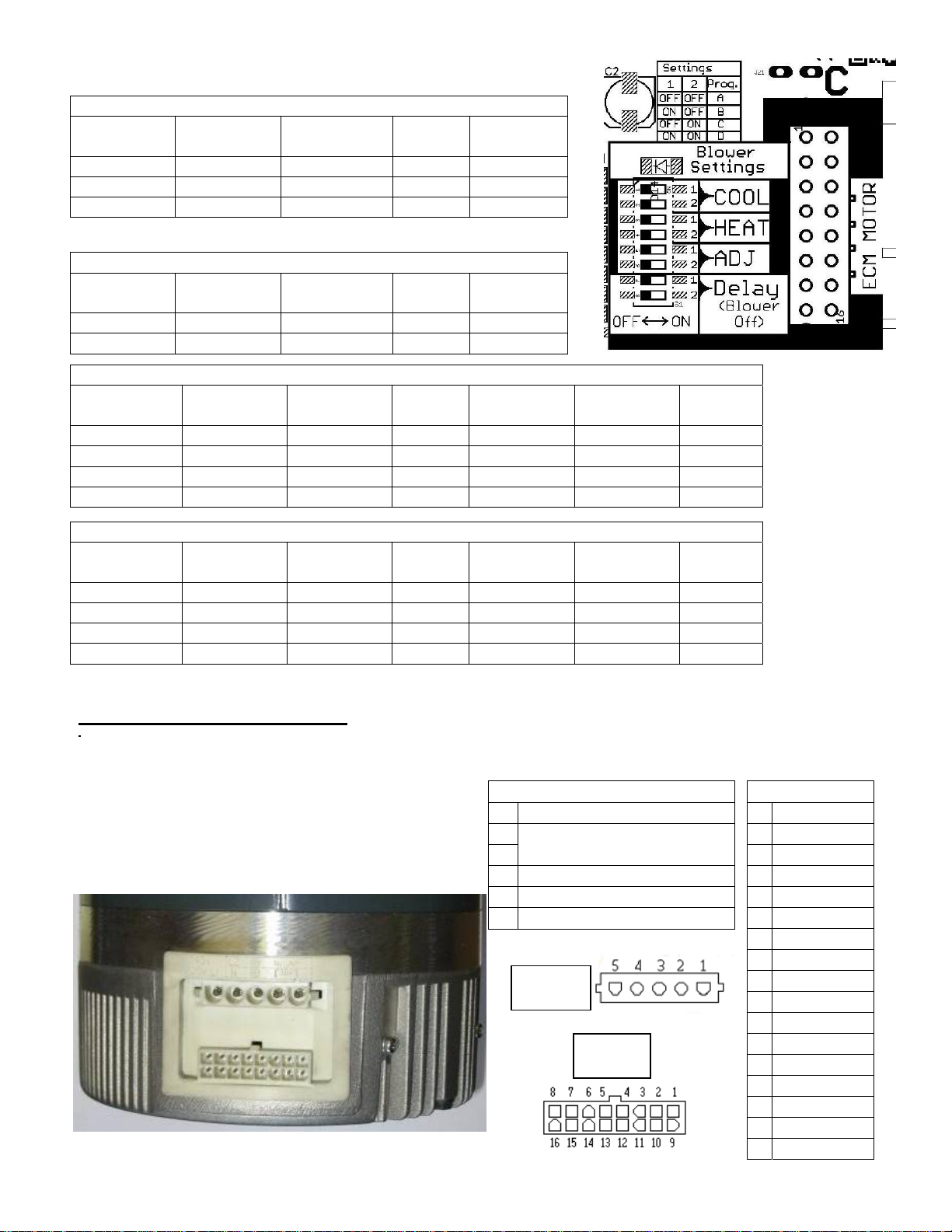
ECM Motor Connections
\
The operation of the motor requires two main connections: the power input connector which is 120VAC,
and the signal input connector from a 24VAC thermostat. Figure 1 shows the location of the connectors
on the motor. When wiring your ECM, the pin
locations are crucial in assuring that no damage is
done to the motor or the control. The figures show
the pin locations for both connectors, when viewing
the motor as shown below
Power Connector
Pin Description
1 JUMPER PIN 1 TO PIN 2
2 120 VAC LINE INPUT
3 CHASSIS GROUND
4 AC LINE
5 AC LINE
Power
connector
Signal
connector
Signal Connector
PinDescription
1 C1
2 W/W1
3 C2
4 DELAY
5 COOL
6 Y1
7 ADJUST
8 OUT9 O
10 BK/PWM
11 HEAT
12 R
13 EM/W2
14 Y/Y2
15 G
16 OUT+
11
 Loading...