

Boyertown nrgMax Universal Oil Control User Manual

nrg
nrgMax
nrgnrg
9103i
9103i
9103i9103i
Advanced Universal Oil
Furnace Control
User's Guide
Max
MaxMax
9103i Advanced
Universal
Oil Furnace Control
OVERVIEW
The nrgMAX 9103i is the only oil-furnace control you will ever
need. It is a feature-rich control designed to meet the needs
of modern energy-efficient oil furnaces while still offering
backwards compatibility with legacy products.
Mounting in the industry-standard footprint with familiar layout
and connections this high quality design meets the needs of
an entire industry sector. It eliminates the need for additional
controls to accommodate Euro-style burners, and offers and
array of variable speed options to suit any requirement.
The control is suitable for use with PSC motors and ECM
motors. ECM motors can be controlled in the common
“thermostat-mode”. PSC motors are controlled with
traditional heavy-duty relay outputs.
OPTIONAL ADVANCED FEATURES
•
Enhanced operation of Standard PSC Blowers
•
Alternate Burner Connection (for burners with postpurge capability)
•
Automatic dehumidification
US and Canadian Patents Pending
FEATURES
•
Industry-standard footprint, mounting and
connections
•
compatible with American burners (Beckett, Carlin
etc) as well as Riello Burners with no additional
relays required
•
Industry-standard 9-pin burner connection
•
120VAC Connections for:
◦
Heat speed motor winding
◦
Cool speed Motor winding
◦
EAC
◦
Humidifier
◦
Continuous Fan
•
24VAC Thermostat Connections for:
◦
5-wire (R,C,W,Y,G), plus
◦
W2 (Stage 2 Heating)
◦
Y2 (Stage 2 cooling)
◦
Yx (dummy connection)
◦
O/B (Heat Pump reversing valve)
◦
DH (Dehumidification)
•
16-pin connection to GE/Beloit-style ECM Motors
•
LED Status indicator
•
Solid-State resettable fuse for 50VA Transformer
protection
•
Double-sided Copper-clad PC board, soldered top
and bottom for optimum strength and durability
•
Multipurpose DIP-switch for field settings
nrgMAX
(division of Bob Tonner Applied Research Inc)
Pickering, ON, 289-800-7131 www.nrgmax.ca
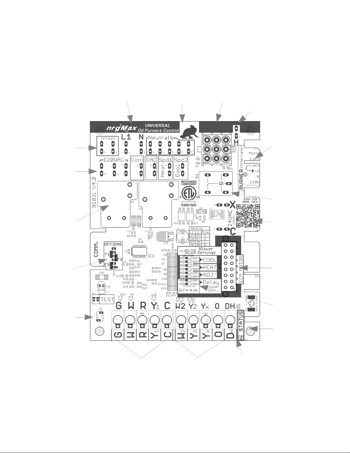
Features and Highlights
Terminals for
unused blower
wires
120VAC outputs
to loads and
accessories
Heavy duty relays
power blowers up
to 15Amps
120VAC Mains
Supply
connections
120VAC
Neutral
Connections
Burner 9-pin
connector
Humidifier
Connection
(120VAC)
Alternate Burner
connection with
continuous
120VAC
Built-in burner
supply relay
(powers limit
string and burner)
24VAC Transformer
input connection.
Protected by Solidstate resettable fuse
Field-selectable
option jumpers:
Extended Blower-
On Delay and/or
Enhanced Mode
Enhanced Low
Voltage Surge
Protection
Standard 5-wire
thermostat
connections
Extended
thermostat
connections
16-pin connector
for ECM Motors
Multipurpose
Dip-switch for
user settings
Industry-Standard
mounting holes
and footprint
Bright LED for
status indication
SPECIFICATIONS
•
Electrical Ratings:
◦
Power Requirements:
▪
Voltage: 24Vac, 50/60 Hz.
▪
Current: 4 VA at 24 Vac.
▪
PTC Fuse (resettable) trips at 4.5A
◦
Contact Ratings:
▪
Circulating Fan: 15A Full Load, 30A Locked
Rotor at 115 Vac (includes optional EAC
load).
▪
Burner: 5.8 A Continuous Load (7.4A with
interrupted ignition)
•
Settings: Standard Configuration
◦
Heating:
▪
Blower On Delay: 30 or 75 seconds, fieldadjustable
▪
Blower Off Delay (BOD): 90, 120, 150, 180
seconds, field-adjustable.
◦
Timing Tolerance: less than 1 second
•
Environmental Ratings:
◦
Temperature: -40 to +150° F [-40° to +66° C].
◦
Humidity: 95% maximum, non-condensing.
Terminals and Connections:
Low Voltage:
•
Thermostat:
◦
G: Blower On
◦
W: Call for heat (0.08A load)
◦
R: 24VAC out to thermostat
◦
Y1: Cooling, Stage 1
◦
C: 24Vac common
◦
W2: Heating, Stage1
◦
Y2: Cooling, Stage2
◦
Yx: Dummy terminal, no connection
◦
O: Heat pump reversing valve
◦
DH: Dehumidification
Line Voltage:
•
Unused: No connection (2 terminals)
•
L1: 120VAC 60Hz, 1ph, 15 A mp (Max) supply
•
N: 120VAC Neutral supply
•
Neutrals: Connection points for loads, tied internally
to N (6 terminals)
•
120VAC : L1 supply to accessories, continuously
powered (3 terminals)
•
Cont. 120VAC to Continuous speed of blower.
Normally energized, it is de-energized whenever
Cool or Heat terminals are energized
•
EAC: 120VAC to Electronic Air Cleaner.
Energized along with Cool or Heat terminals
•
Heat: 120VAC 15A, 1HP blower speed.
•
Cool: 120VAC 15A, 1HP blower speed
•
H: 120VAC 1A to Humidifier. Powered by
burner motor feedback (Pins 7-8 on 9-pin burner
connector).
Burner Connections:
•
9-PIN AMP Connector:
(MATES WITH TYCO PART #350720)
1) Safety Limit string (return)
2) 120VAC to Oil Burner (high-limit protected)
3) Burner T-T (internally connected to Pin 6)
4) Neutral (internally connected to Pin5 and N)
5) Neutral (internally connected to Pin 4 and N)
6) Burner T-T (internally connected to Pin 3)
7) Burner Motor (internally connected to Pin 8)
8) Burner Motor (internally connected to Pin 7)
9) 120VAC to Safety Limit string. Normally off,
energized on call for heat by Relay K1
•
Edge Connector (Alternate, 6 conductor) mates with
Molex 09-01-6061.
◦
Motor: Burner Motor
◦
Limit: 120VAC to Safety Limit string. Normally
off, energized on call for heat by Relay K1
◦
Limit: Safety Limit string (return)
◦
L1: 120VAC to Oil Burner (high-limit
protected)
◦
120V: 120VAC Continuous (not limit protected)
• CLASS 2 TRANSFORMER 50VA Max (overload
protected)
◦
X: 24VAC
◦
C 24VAC Common
•
16-PIN ECM Connector: Convenient interface
between 10-position thermostat, DIP-switches and
ECM motors.
•
•
Option Jumpers: Selectable Options:
◦
F1 Reserved
◦
F2 Enhanced PSC Mode
◦
F3 Extended Blower On Delay (75 Sec)
nrgMAX
(division of Bob Tonner Applied Research Inc)
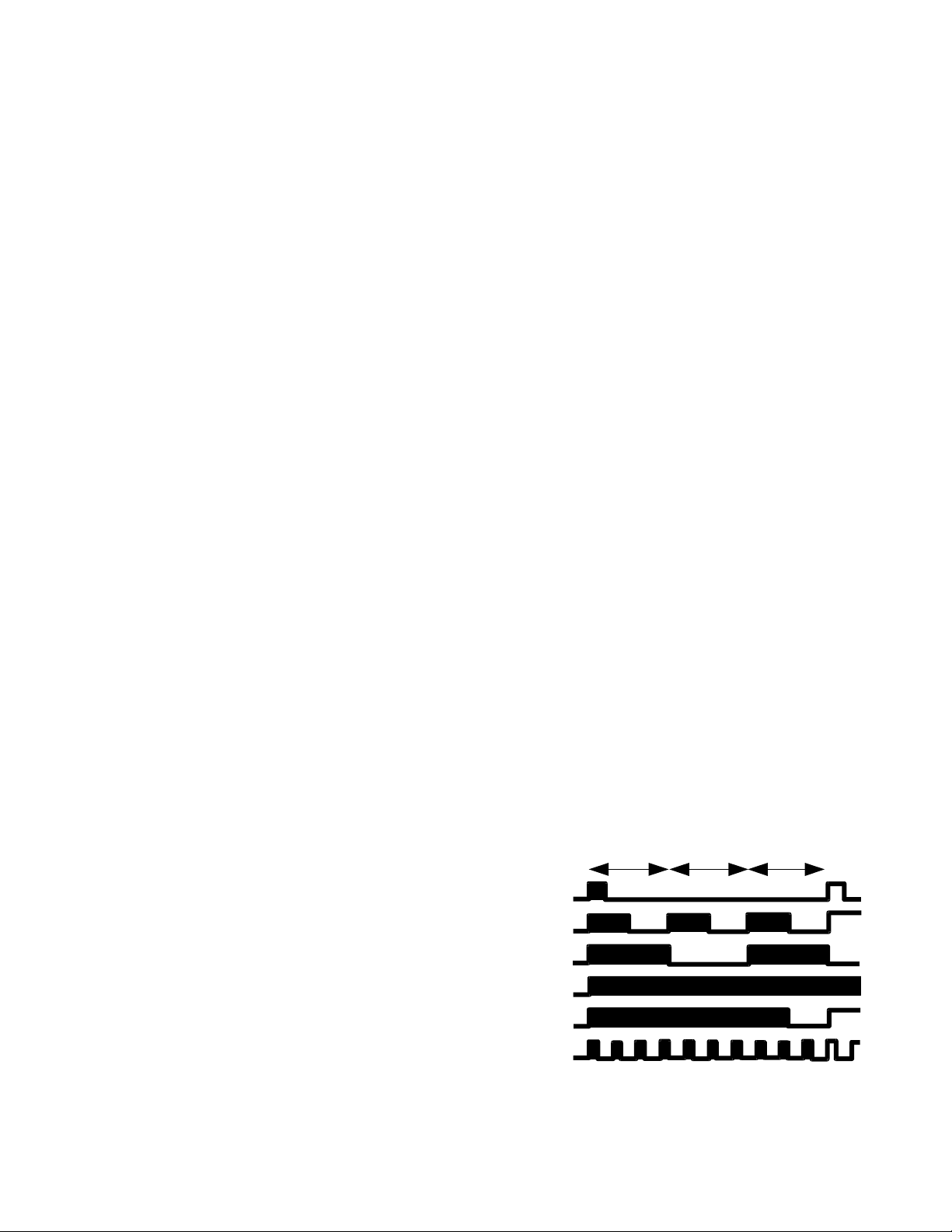
Status LED Flashing Patterns
1
Standby
Heating
Cooling
Limit
Limit reset
No Burner
Pickering, ON, 289-800-7131 www.nrgmax.ca
sec
1
sec
1
sec

OPERATIONAL MODES:
All operational modes are simultaneously active on
the 9103i, and the user needs only to make the
appropriate connections to make use of them. The
DIP-Switch is interpreted by the on-board software
differently for each mode of operation.
•
Standard PSC: Blower motor is driven by on-board
heavy duty relays. Heat, Cool and Continuous
speeds are available from 0.250” male spade
terminals clearly marked on board. Compatible with
all 5+ wire thermostats and responds to:
◦
W: heating
◦
Y1: cooling
◦
Y2: cooling
◦
G: Blower On
◦
DIP-Switch:
▪
Blower Off Delay (BOD):
•
A: 90 Seconds
•
B: 120 Seconds
•
C: 150 Seconds
•
D: 180 Seconds
▪
Heat: no function
▪
Cool: no function
▪
Adj: no function
OPTION:
Enhanced PSC Mode is selected by placing the
option jumper across position #3 and #4 on the
Option Select pins (See “Setting Options”). All wiring
and connections remain the same as the Standard
PSC mode, however the operation is enhanced.
ENABLE THIS OPTION ONLY WHEN THE COOL
TERMINAL IS CONNECTED TO A HIGHER
BLOWER SPEED THAN HEAT OUTPUT.
EXAMPLE:
“HEAT” CONNECTED TO MED-HIGH
“COOL” CONNECTED TO HIGH
speed
◦
DH (NO 24V signal): immediately
drops from Cool speed to Heat speed
to dehumidify.
◦
DH (24V signal returns): Blower
stepped up to Cool speed
◦
Y2 (24V signal) overrides DH and Y1
keeping Cool terminal on as long as
signal on Y2 is present
◦
G (24V signal alone without Y1, Y2, or
W): energizes Heat terminal
Note: for 2-stage cooling in Enhanced mode use Yx
and Y2. Yx is a dummy terminal and is ignored by
the control logic but provides a convenient
connection point for the AC compressor. When the
thermostat calls for stage 1 cooling (a Y1 signal from
the thermostat) it is terminated at Yx, but the
thermostat also activates G simultaneously. The
9103i then energizes the lower speed Heat terminal
as long as the condition exists. If Y2 is energized
(together with Y1/G, or separately) the control will
switch to Cool speed. This allows for 2 different
blower speeds for 2-stage cooling
• ECM Mode: ECM Motor handles all blower speed
logic in factory-set “thermostat mode” and it monitors
all ten thermostat inputs. The 9103i control
energizes the EAC and H terminals normally. While
the DIP-Switch settings are now directed to the ECM
motor through the 16-pin connector the 9103i will
continue to interpret the BOD settings to establish
the delay period before de-energizing EAC terminal.
Please note that the OEM factory -settings for the
ECM blower-off delay may not co-ordinate with the
EAC delay. The 9103i Controller has no influence
over the ECM motor as all signals are “passthrough” only.
• Heating:
◦
W (24V signal) activates Heat Speed
output
◦
W+W2 (24V signals) activate Cool
Speed.
• Cooling: Blower is initially started on Heat
Speed for 4 minutes to allow for
dehumidification, after which the blower
switches to Cool Speed. If the the 24VAC
signal to the DH terminal opens this signals
a call to dehumidify and the blower drops
down to heat speed to encourage greater
condensation across the cooling coil. When
the 24VAC signal reappears on DH the
blower is switched back up to Cool speed.
◦
Y1 (24V signal): 4 minutes at Heat
speed to dehumidify, then to Cool
 Loading...