

Boyertown CSL6230, CSL12590 User Manual
INSTALLATION AND OPERATOR’S MANUAL
CSL6230 THRU CSL12590
CAST IRON BOILERS
Keep these instructions with the boiler at all times for
future reference
B
OYERTOWN FURNACE CO.
PO Box 100
B
OYERTOWN, PA 19512
1-610-369-1450
www.boyertownfurnace.com
6-1-08

g
2
Be Aware of Hazard Definitions
Danger: Denotes presence of a hazard which, if ignored, will result in severe personal
injury, death or property damage
Warning: Denotes presence of a hazard which, if ignored, could result in severe personal
injury, death or substantial property damage.
Caution: Denotes the presence of a hazard which, if ignored, could result in minor personal
injury or property damage
Notice: Intended to bring attention to information, but not related to personal injury or
property damage.
Warning: This equipment must be installed, adjusted, serviced and started only by a qualified
service agency – an individual or agency, licensed and experienced with all codes and ordinances, and
who is responsible for the installation and adjustment of the equipment. All aspects of the installation
must conform to the authority having jurisdiction, or in the absence of such requirements, to the National
Fuel Gas Code, ANSI Z2231.1/NFPA 54 or to the installation of Oil Burning Equipment, NFPA 31.
Read all instructions before proceeding. Follow all instructions completely. Failure to follow these
instructions could result in equipment malfunction causing severe personal injury, death or substantial
property damage.
Do not alter this boiler in any way. The manufacturer will not be liable for any damage resulting from
changes made in the field to the boiler or its components or from improper installation. Failure to comply
could result in severe personal injury, death, or substantial property damage.
Your oil fired boiler is designed to burn natural gas, LP gas, No. 1 or No. 2 heating oil only. Never use
gasoline or a mixture of gasoline and oil.
Do not store gasoline or other flammable vapors and liquids in the vicinity of this or any other appliance.
The area around the boiler should be kept free and clear of combustible materials.
Never burn garbage or refuse in your boiler.
Never try to ignite oil by tossing burning papers or other material into your boiler.
Do not attempt to start the burner when excess oil vapors or gas has accumulated in the boiler.
D
Do not jumper, attempt to bypass, or override any of the safety limit controls.
Do not use this boiler if any part has been under water. Immediately call a qualified service technician to
inspect the boiler and replace any part of the boiler, control system or burner that has been under water.
All installations must conform to the requirements of the authority having jurisdiction. Such applicable
requirements take precedence over the general instructions of this manual.
Where required by the authority having jurisdiction, the installation must conform to the American
Society of Mechanical Engineers Safety Code for Controls and Safety Devices for Automatically Fired
Boilers, ANSI/ASME CSD-1.
Warnin
o not operate boiler if the heat exchanger is damaged.

Warning:
producing carbon monoxide (CO). Carbon monoxide (CO) is a gas which is odorless, tasteless
and colorless but is very toxic.
If your boiler is not vented properly or is not working properly, dangerous levels of CO may
accumulate. CO is lighter that air and may travel throughout the building. Brief exposure to high
levels of CO or prolonged exposure to lesser amounts of CO may result in carbon monoxide
poisoning.
Exposure can be fatal and exposure to high concentrations may result in the sudden onset of
symptoms including unconsciousness.
Symptoms of CO poisoning include the following:
Dizziness Vision Problems Shortness of Breath
Headaches Loss of Muscle Control Unclear Thinking
Nausea Weakness Unconsciousness
The symptoms of CO poisoning are often confused with influenza, and the highest incidence of
poisoning occurs at the heating season which is during flu season. A victim may not experience
all of the listed symptoms. Suspect the presence of CO if the symptoms tend to disappear when
you leave your home.
The following sign may indicate the presence of carbon monoxide:
If any of these symptoms of CO poisoning occur, or if any of the signs of carbon monoxide are
present, leave the premises immediately and contact a qualified service company, the gas
company or the fire department.
To reduce the risk of CO poisoning have your heating system, vent system and chimney
inspected and serviced before each heating season
Any Appliance that burns natural gas, propane gas or fuel oil is capable of
• Hot gasses from the appliance, venting system or chimney escaping into the living
area.
• Flames coming out around the appliance.
• Yellow colored flames in the appliance when burning gas.
• Stale or smelly air.
• The presence of soot or carbon in or around the boiler.
• High unexplained humidity inside the building.
3
Notice: Concealed Damage - If you discover damage to the burner, boiler or controls
during unpacking, notify the carrier at once and file the appropriate claim. When calling or
writing about the boiler please have the following information available: the boiler model
number and serial number which is located on the upper left front of the unit. Record the
model and serial number for future reference in the space provided in this manual.

4
Table of Contents
Ratings and Data
Clearances 6
Ventilation and Combustion Air 6
Boiler Assembly 6
Boiler Trim Piping 8
System Piping 9
Jacket Installation 9
Venting 15
Burner Installation 17
Fuel Piping 18
.
Wiring 18
Operation 20
Burner Settings 21
..
Maintenance 23
Warranty 23
Installation and Service Check List 24
5
Ratings and Data
5
Ratings
Boiler Model No. CSL6230 CSL7290 CSL8350 CSL9410 CSL10470 CSL11530 CSL12590
Firing Rate - #2 Fuel 2.30 2.90 3.50 4.10 4.70 5.30 5.90
Input BTU/HR 322,000 406,000 490,000 574,000 658,000 742,000 826,000
Output BTU/HR 276,000 352,000 426,000 501,000 575,000 649,000 723,000
Net Output BTU/HR 240,000 306,000 370,000 436,000 500,000 564,000 629,000
Net Rating Sq. Ft. 1600 2040 2465 2910 3335 3760 4195
Water Capacity Gals. 17 20 23 26 29 32 35
Approx. Shipping Weight Lbs 1170 1300 1435 1540 1660 1785 1900
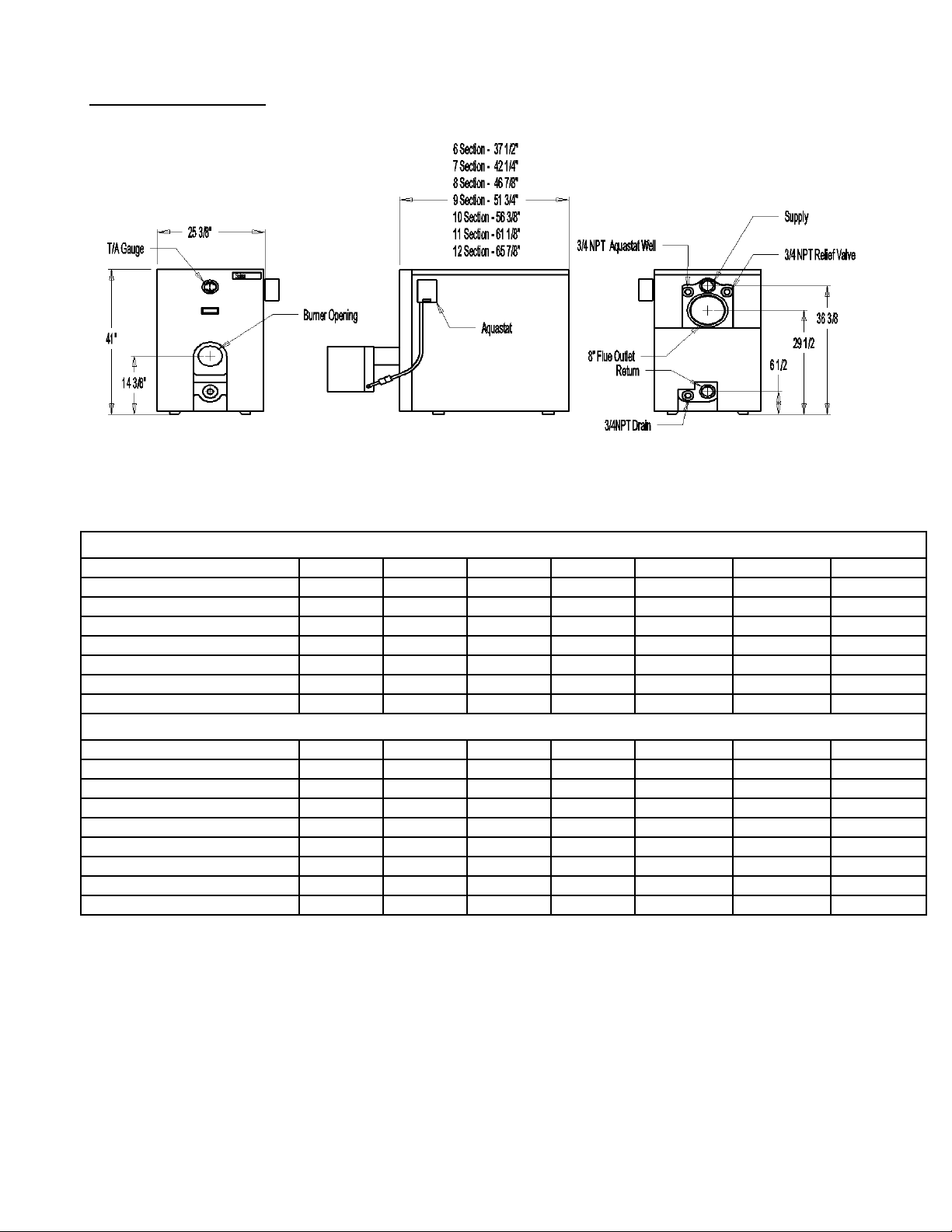
Dimensions
Cabinet Height 41-1/8” 41-1/8” 41-1/8” 41-1/8” 41-1/8” 41-1/8” 41-1/8”
Cabinet Width 25-3/8” 25-3/8” 25-3/8” 25-3/8” 25-3/8” 25-3/8” 25-3/8”
Cabinet Length 37-1/2” 42-1/4” 46-7/8” 51-3/4” 56-3/8” 61-1/8” 65-7/8”
Supply Outlet Size NPT 2” 2” 2” 2” 2-1/2” 2-1/2” 2-1/2”
Supply Outlet Height C.L. 34-1/8 34-1/8 34-1/8 34-1/8 34-1/8 34-1/8 34-1/8
Return Size NPT 2” 2” 2” 2” 2-1/2” 2-1/2” 2-1/2”
Return Outlet Height C.L. 3-7/8” 3-7/8” 3-7/8” 3-7/8” 3-7/8” 3-7/8” 3-7/8”
Flue Outlet Diameter 8” 8” 8” 8” 8” 8” 8”
Flue Outlet Height C.L. 34-1/4 34-1/4” 34-1/4” 34-1/4” 34-1/4” 34-1/4” 34-1/4”

6
Boiler Components
INSPECT FOR DAMAGE. All equipment is carefully manufactured, inspected, and packaged by
experienced workers. Our responsibility ceases upon delivery of the skidded boiler and component
boxes to the carrier in good condition. ANY CLAIMS FOR DAMAGE OR SHORTAGES IN
SHIPMENT MUST BE FILED IMMEDIATELY against the carrier by the consignee.
The boiler is shipped in multiple packages consisting of the following items:
1. Assembled casting strapped to a skid.
2. Cabinet parts box. See jacket assembly instructions for a complete listing of all items
included.
3. Burner/Parts Box – Includes burner, aquastats, low water cutoff, safety relief valve,
drain valve and associated trim piping. See packing list included in box for a
complete list of all components.
Installation Clearances
Warning: Boilers in rooms shall be installed with the clearances from combustible
materials not less than indicated below. Combustible materials are those made of or
surfaced with wood, compressed paper, plant fibers, plastics, or other material that will ignite
and burn, whether flame proofed or not, or whether plastered or not.
The boiler must not be installed on combustible flooring. The boiler is approved for installation
on non combustible flooring only. The boiler must not be installed on carpeting or vinyl flooring
Minimum clearances to combustible construction are as follows:
TOP - 24 IN.
FRONT - 24 IN.
FLUE CONNECTOR SINGLE WALL VENT PIPING - 18 IN.
REAR -6 IN.
SIDES - 6 IN.
Consult NFPA-31 for construction techniques where the above minimum clearances cannot be obtained
Minimum recommended clearances for service and access are as follows:
TOP - 24 IN.
FRONT - 24 IN. FROM BURNER
FLUE CONNECTOR - 18 IN.
REAR - 18 IN.
SIDES - 12 IN.
Ventilation and Combustion Air
Warning: This boiler must be supplied with combustion and ventilation air in
accordance with ANSI Z223.1/NFPA54 and all applicable local codes. Air openings to
combustion area must not be obstructed. Adequate combustion air must be supplied at all
times. Ventilation of boiler room must be adequate enough to provide sufficient air for
combustion. Never use an exhaust fan in the boiler room. The boiler room must never be
under a negative pressure or improper burner operation, flue gas leakage and carbon
monoxide emissions may occur.
Opening sizes must comply with state or local codes. In their absence, use the following when the boiler is
installed in a confined room:
7
When a boiler is located in an unconfined space in a building of conventional frame or masonry
construction infiltration may provide adequate air for combustion and ventilation. If there is any doubt,
nstall air supply provisions for combustion and ventilation air. i
When a boiler is located in a confined space and air for combustion and room ventilation is from
inside buildings, the confined space shall be provided with two permanent openings, one starting 12
inches from the top and one 12 inches from the bottom of the enclosed space. Each opening shall
have a minimum free area of 1 square inch per one thousand (1,000) BTU/HR of the total input
rating of all appliances in the enclosed space, but must not be less than one hundred (100) square
inches. These openings must freely communicate with the interior areas having adequate
infiltration from the outside.
When a boiler is installed in a confined space, or in a building of unusually tight construction, air for
combustion and room ventilation must be obtained from the outdoors by means of two permanent openings
one starting 12 inches from the top and one 12 inches from the bottom of the enclosed space. When air is
taken through the outside wall or vertical ducts, at least one square inch of free opening must be provided per
4000 Btu/Hr. When air is taken through horizontal ducts at least one square inch of free opening must be
provided per 2000Bth/Hr. The minimum dimensions of rectangular air ducts shall not be less than 3 inches.
In calculating free area using louvers, grills or screens for the above, consideration shall be given to their
blocking effect. Screens used shall not be smaller than ¼ inch mesh. If free area through a design of louver
or grill is known, it should be used in calculating the opening size required to provide the free area specified.
If the design and free area is not known, it may be assumed that wood louvers will have 20-25% free area
and metal louvers and grills will have 60-75% free area.
Louvers and grills shall be fixed in the open position or interlocked with the boiler so that they are opened
automatically during boiler operation.
Boiler Location
Warning:
Never install the boiler on top of combustible flooring. Never install the boiler in
an area where combustible materials, gasoline or any other products containing flammable vapors
or liquids are stored.
Locate the boiler in an area that provides good access to the unit. To provide the best possible serviceability
the boiler should be installed using the minimum recommended service and accessibility clearances as
previously listed. Under no circumstances should the unit be installed next to combustible materials with
learances less than listed in installation clearances above. c
The boiler should be installed on a level, flat concrete floor or pad that is structurally sound and will support
the combined weight of the boiler when filled with water. This boiler is designed to be installed on
noncombustible flooring only.
The boiler should be installed as close to the chimney as possible while still being located centrally to the
piping system.
Boiler Block Assembly
All boilers are shipped as an assembled block. If it is necessary to split the block into sections for
installation purposes reassemble the sections as follows:
To assemble split blocks, move the sections into line facing each other. Sections may be slid along boards
placed beneath the sections. Inspect nipple ports for damage or burrs. Remove any burrs by brushing the
ports very lightly. Remove old section sealant from the castings. Wipe the push nipples and nipple ports
with a clean cloth. Apply a film of nipple compound to both nipple and port. Install the nipple in the port
and then seal by hitting with a rubber mallet. Apply section sealant to one section only and slide the
sections together. Install the four draw rods. Draw the sections together until the sections make iron to iron
contact at a point around the top and bottom ports of each section. Check to ensure that the combustion
chamber is sealed using a flash light or other lighting device. Place the light into the combustion chamber
8
and look for light on the floor or surrounding walls (this is best done in a dark room). If light appears out of
the boiler, reseal between the sections.
Boilers which were split for installation will need to be hydrostatic pressure tested in accordance with
Section IV of the ASME Boiler and Pressure Code at a pressure equal to 1-1/2 times the maximum
allowable pressure on the boiler nameplate.
Caution: Do not hydrostatically test the boilerwith any controls installed. Damage to
controls can occur due to over pressure.
Warning: Do not leave boiler unattended during hydrostatic testing. Cold water fill could
expand as it warms causing excessive pressure, resulting in severe injury, death or substantial
property damage. Leaks, if found, must be repaired immediately. Failure to do so can damage
boiler, resulting in substantial property damage.
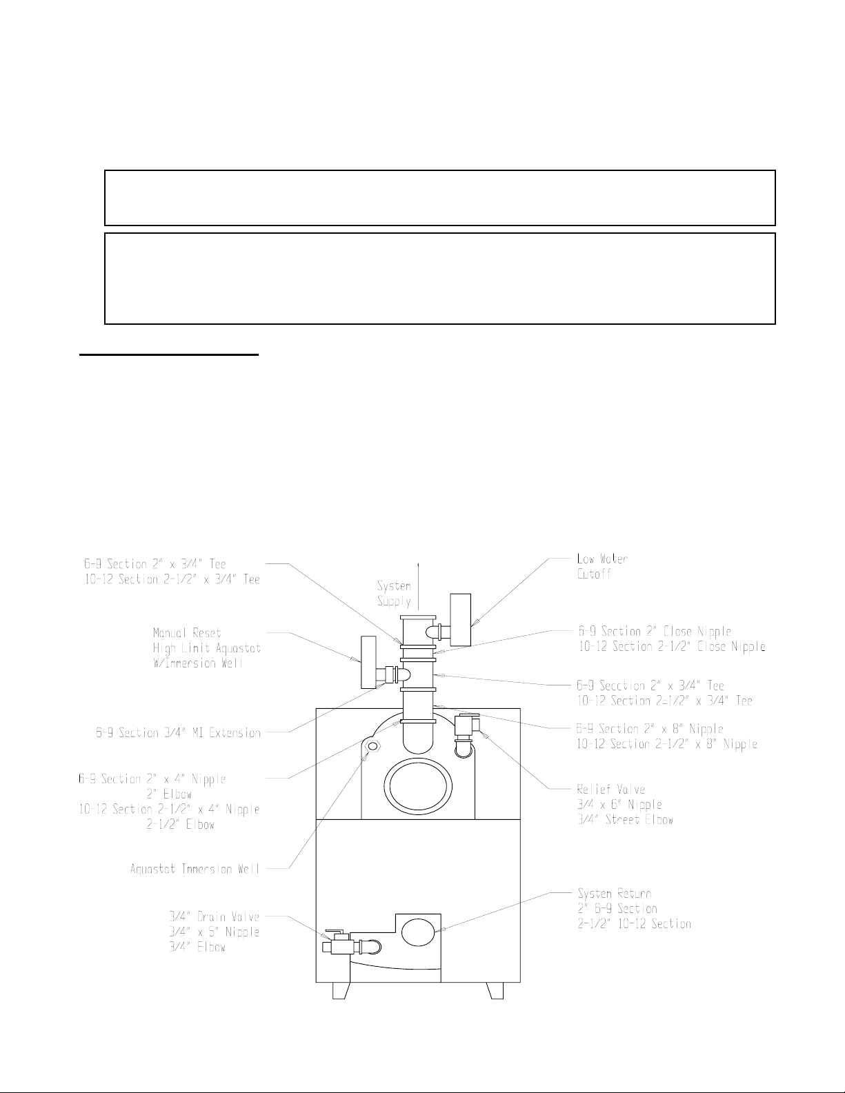
Boiler Trim Piping
1. Install the ¾” aquastat immersion well in upper right side tapping of the rear boiler section. Install the
temperature sensor all the way into the well until it hits bottom and fasten in place with the retaining
clip as provided.
2. Pipe in pressure relief valve with ¾” street elbow and with the ¾” x 3” nipple in upper left side of the
rear section. Relief valve discharge must be piped to a safe place of discharge. See system piping.
3. Pipe in boiler drain with ¾” coupling and the ¾” x 6” nipple in the lower left side rear section.
4. Pipe in boiler gauge with ½” x ¼” reducing bushing in upper front section.
5. Install auxiliary high limit aquastat and low water cutoff as shown using the provided piping.

System Piping
Important… INSTALLATION MUST BE PERFORMED BY A TECHNICALLY
QUALIFIED SERVICEMEN.
SOLAIA COMMERCIAL BOILERS HAVE A MAXIMUM OPERATING PRESSURE OF 58PSI
NOTE: If normal operating pressures are greater than 30psi please contact the manufacturer for required
trim.
Pipes that are connected to boiler fittings must be supported and placed so that they do not create stresses on
the boiler fittings themselves.
The Solaia boiler is a highly efficient boiler in which care must be taken to ensure that high volumes of low
temperature water are not introduced into the boiler. Operating at return water temperatures below 130ºF
for extended periods of time will allow for the accumulation of condensation, scale and increased soot
formation in the boiler. Corrosion and eventual heat exchanger failure will result.
Low water cut off
A low water cutoff has been provided with the boiler package. See boiler trim piping for the recommended
location. Always follow the low water cutoff manufacturer’s recommendations for installation.
Relief Valves
Warning: The discharge of the pressure relief or safety valve must be piped close to the
floor to prevent scalding in the event of a discharge. The discharge piping must be sized the
same as the valve outlet. Never install any valve between the boiler and the safety valve or in the
discharge piping. Failure to comply with this warning can result in an explosion causing property
damage, severe personal injury, or death.
Relief valves are to be properly piped in to conform to code standards. Discharge piping from the relief
valve must be sufficiently supported so as to avoid strain on the safety valve body.
Discharge piping should terminate 6” above the floor to eliminate damage to the structure or personal injury.
It should be piped to a location where it can be inspected for any visible signs of leakage. It must not be
piped to a point where freezing may occur.
9
Jacket Installation
The boiler jacket is designed so that all piping connections can be made before the Jacket is installed.
Jacket Components
2) Mounting Brackets A
(2) Mounting Brackets B
(1) Front Panel
(1) Upper Rear Panel
(1) Lower Rear Panel
(1) Left Front Panel
(1) Left Rear Panel
Trim Bag Components
(10) #8 x 1/2” Hex Washer Head Self Drilling
Screws
(60) #10 x 3/4” Hex Washer Sheet Metal
Screws
(6) #10 x 5/8” Phillips Flat Head Screws
(6) Brass Cup Washers
(1) Right Front Panel
(1) Right Rear Panel
(1) Top Front Panel
(1) Top Rear Panel
(1) Insulation Strip 3” x 48” x 87”
(1) Insulation Strip 3” x 12” x 87”
(1) Insulation Rear Panel
(1) Trim Bag
(3) Lengths Plastic Strapping – 11 Ft.
(3) Strapping Clips
(6) Feet Foil Tape
(4) SB875-11 Anti Short Bushin
gs
 Loading...