

Page 1
P12 Projector
User Guide
mimio.boxlight.com
Page 2

Table of Contents ............................2
Usage Notice ...................................3
Safety Information ...............................3
Precautions .........................................4
Introduction ......................................6
Package Overview ..............................6
Product Overview ...............................7
Main Unit .............................................. 7
Control Panel ....................................... 8
Interface ............................................... 9
Remote Control .................................. 10
Installation ..................................... 11
Connecting the Projector ..................11
Connect a Desktop/Laptop Computer 11
Powering the Projector On / Off ........13
Powering On the Projector ................. 13
Powering Off the Projector ................. 14
Warning Indicator ............................... 14
Adjusting the Projected Image ..........15
Adjusting the Projector�s Height ........ 15
Adjusting the Projector�s Focus ......... 16
Adjusting Projection Image Size
(Diagonal) .......................................... 17
User Controls ................................19
Control Panel & Remote Control ......19
Control Panel ..................................... 19
Remote Control .................................. 20
On-screen Display Menus ................22
How to operate ................................. 22
Picture ................................................ 23
Screen ............................................... 25
Setting ................................................ 27
Volume ............................................... 29
Options .............................................. 30
Options | Lamp Settings .................... 32
3D ...................................................... 33
Interactive .......................................... 34
LAN .................................................... 35
Replace the Lamp .............................41
Appendices ....................................41
Installing and Cleaning the Optional
Dust Filter .........................................43
Compatibility Modes .........................44
VGA Analog ....................................... 44
HDMI Digital ....................................... 45
List of specifications ..........................48
Wall Mount Installation ......................50
Regulation & Safety Notices .............51
Table of Contents
Page 3
Safety Information
The lightning ash with arrow head within an equilateral triangle is
intended to alert the user to the presence of uninsulated “dangerous
voltage” within the product’s enclosure that may be of sufcient
magnitude to constitute a risk of electric shock to persons.
The exclamation point within an equilateral triangle is intended to alert
the user to the presence of important operating and maintenance
(servicing) instructions in the literature accompanying the appliance.
WARNING: TO REDUCE THE RISK OF FIRE OR ELECTRIC SHOCK, DO NOT
EXPOSE THIS APPLIANCE TO RAIN OR MOISTURE. DANGEROUS HIGH
VOLTAGES ARE PRESENT INSIDE THE ENCLOSURE. DO NOT OPEN THE
CABINET. REFER SERVICING TO QUALIFIED PERSONNEL ONLY.
Class B emissions limits
This Class B digital apparatus meets all requirements of the Canadian
Interference-Causing Equipment Regulations.
Important Safety Instruction
1. Do not block any ventilation openings. To ensure reliable operation of
the projector, and to protect from over heating, it is recommended to
install the projector in a location that does not block ventilation. As an
example, do not place the projector on a crowded coffee table, sofa,
bed, etc. Do not put the projector in an enclosure such as a book case
or a cabinet that restricts air flow.
2. Do not use the projector near water or moisture. To reduce the risk
of fire and/or electric shock, do not expose the projector to rain or
moisture.
3. Do not install near heat sources such as radiators, heaters, stoves or
any other apparatus, such as amplifiers, that emits heat.
4. Clean only with dry cloth.
5. Only use attachments/accessories specified by the manufacturer.
6. Do not use the unit if it has been physically damaged or abused.
Physical damage/abuse would be (but not limited to):
Unit has been dropped.
Power supply cord or plug has been damaged.
Liquid has been spilled on to the projector.
Projector has been exposed to rain or moisture.
Something has fallen in the projector or something is loose inside.
Do not attempt to service the unit yourself. Opening or removing covers
may expose you to dangerous voltages or other hazards.
7. Do not let objects or liquids enter the projector. They may touch
dangerous voltage points and short out parts that could result in fire or
electric shock.
8. The unit should only be repaired by appropriate service personnel.
Page 4
Precautions
Please follow all warnings, precautions, and
maintenance as recommended in this user�s
manual.
▀■ Warning- Do not look into the projector’s lens when the lamp is
on. The bright light may hurt and/or damage your eyes.
▀■ Warning- To reduce the risk of re or electric shock, do not
expose this projector to rain or moisture.
▀■ Warning- Please do not open or disassemble the projector as
this may cause electric shock.
▀■ Warning- Before replacing the lamp, please have the projector
completely cooled down. Operate as described on
Pages 48-49.
▀■ Warning- This projector will automatically detect the service life
of its lamp. When the projecor shows a warning message, the lamp must be replaced “immediately”.
▀■ Warning- After replacement of the lamp module, please reset
the lamp hour counter (see Page 49).
▀■ Warning- When switching the projector off, please ensure
the cooling cycle has been completed before
disconnecting power. Allow 90 seconds for the
projector to cool down.
▀■ Warning- When service life of the lamp is about to expire, the
“Lamp Warning: Exceed Service Life” message will
be shown on the screen. Please contact the local
dealer or service center to replace the lamp as soon
as possible.
When service
life of the lamp
expires, the lamp
module must
be replaced.
Otherwise, the
projector cannot
be switched on.
To replace the
lamp, please
follow the
steps stated in
“Replace the
Lamp” on Pages
48-49.
Page 5

5
Do:
Turn off and unplug the power plug from the AC outlet before
cleaning the product.
Use a soft, dry cloth with mild detergent to clean the display
housing.
Disconnect the power plug from AC outlet if the product is not
being used for a long period of time.
Do not:
Block the slots and openings on the unit provided for ventilation.
Use abrasive cleaners, waxes or solvents to clean the unit.
Use under the following conditions:
- In extremely hot, cold, or humid environments.
Ensure that the ambient room temperature is within 5 - 40°C.
Relative Humidity is 5 - 40°C, 80% (Max.), non-condensing.
- In areas susceptible to excessive dust and dirt.
- Near any appliance generating a strong magnetic eld.
- In direct sunlight.
Page 6
6
Power Cord
Package Overview
Unpack and inspect the box contents to ensure
all parts listed below are in the box. If something
is missing, please contact your nearest customer
service center.
2 × AAA Batteries
Projector
VGA Cable
IR Remote Control CD-ROM
(User’s Manual)
Page 7
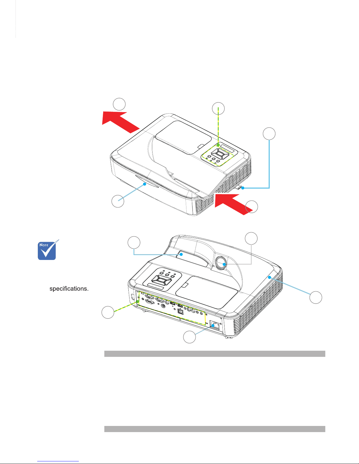
Product Overview
Main Unit
1. Control Panel
2. Focus Switch
3. Ventilation (inlet)
4. IR Receiver
5. Ventilation (outlet)
6. Speaker
7. Power Socket
8. Input / Output
Connections
9. Lens
10. IR Camera
The interface
is subject to
model’s
7
8
4
2
5
3
1
10
6
9
Page 8
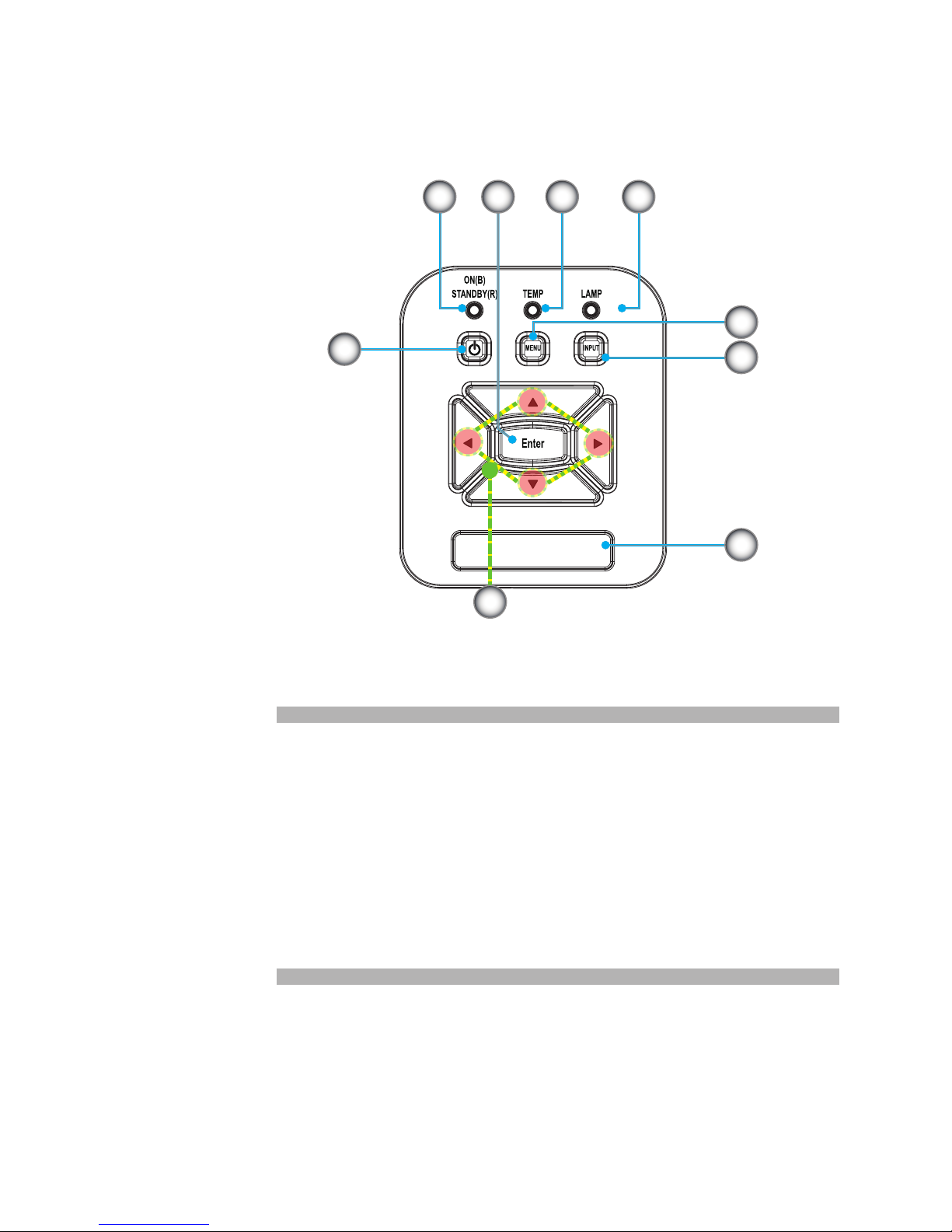
Control Panel
1. Power LED
2. Enter
3. Temp LED
4. Lamp LED
5. Menu
6. Signal source
7. Four Directional Select Keys
8. Power/Standby button
9. IR Receiver
3
6
9
8
7
21 4
5
Page 9
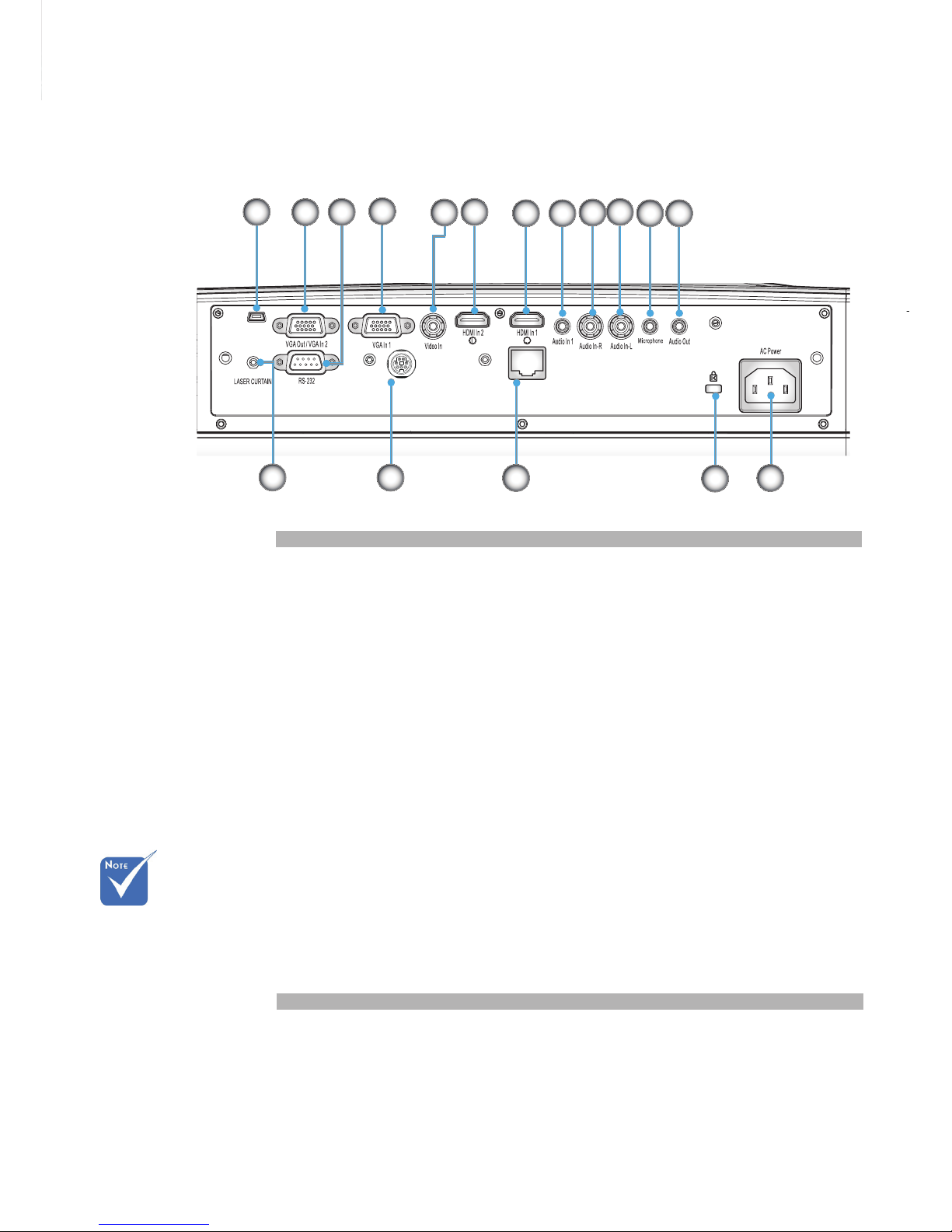
Interface
Monitor loop
through only
support in VGA
IN1-In/YPbPr.
1. USB Connector (For FW upgrade and interactive function)
2. VGA-Out/VGA-In2 Connector
3. RS-232 Connector (9-pin DIN Type)
4. VGA-In1/YPbPr Connector (PC Analog Signal/Component
Video Input/HDTV/YPbPr)
5. Composite Video Input Connector
6. HDMI2 Input Connector
7. HDMI1 Input Connector
8. Audio Input Connector (3.5mm mini jack)
9. Composite Audio Input (right) Connector
10. Composite Audio Input (left) Connector
11. Audio Input Connector (microphone connector)
12. Audio Output Connector (3.5mm mini Jack)
13. Power Socket
14. KensingtonTM Lock Port
15. RJ45 Connector
16.
17.
ECP
Laser Curtain (Optional)
RJ45
USB
ECP
2
1
4
13
3
5
6
7 8
9
10
11 12
14
15
17
16
Page 10
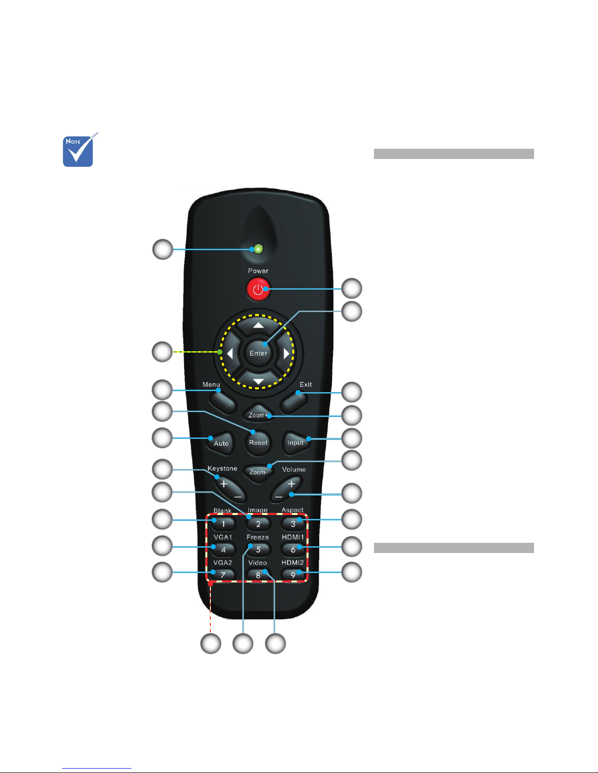
Remote Control
The specic inter-
faces are selected
in terms of the
specications of
types.
1. LED Indicator
2. Power On/Off
3. Enter
4. Four Directional Key
5. Menu
6. Exit
7. Zoom +
8. Reset
9. Auto
10. Input
11. Zoom -
12. Volume +/-
13. Keystone +/-
14. Image
15. Blank
16. Aspect ratio
17. VGA1
18. HDMI1
19. VGA2
20. HDMI2
21. Video
22. Freeze
23. Numbered keypad
(for password input)
16
2122
19
17
15
8
14
12
20
23
1
10
13
9
6
11
5
4
2
3
7
18
Page 11
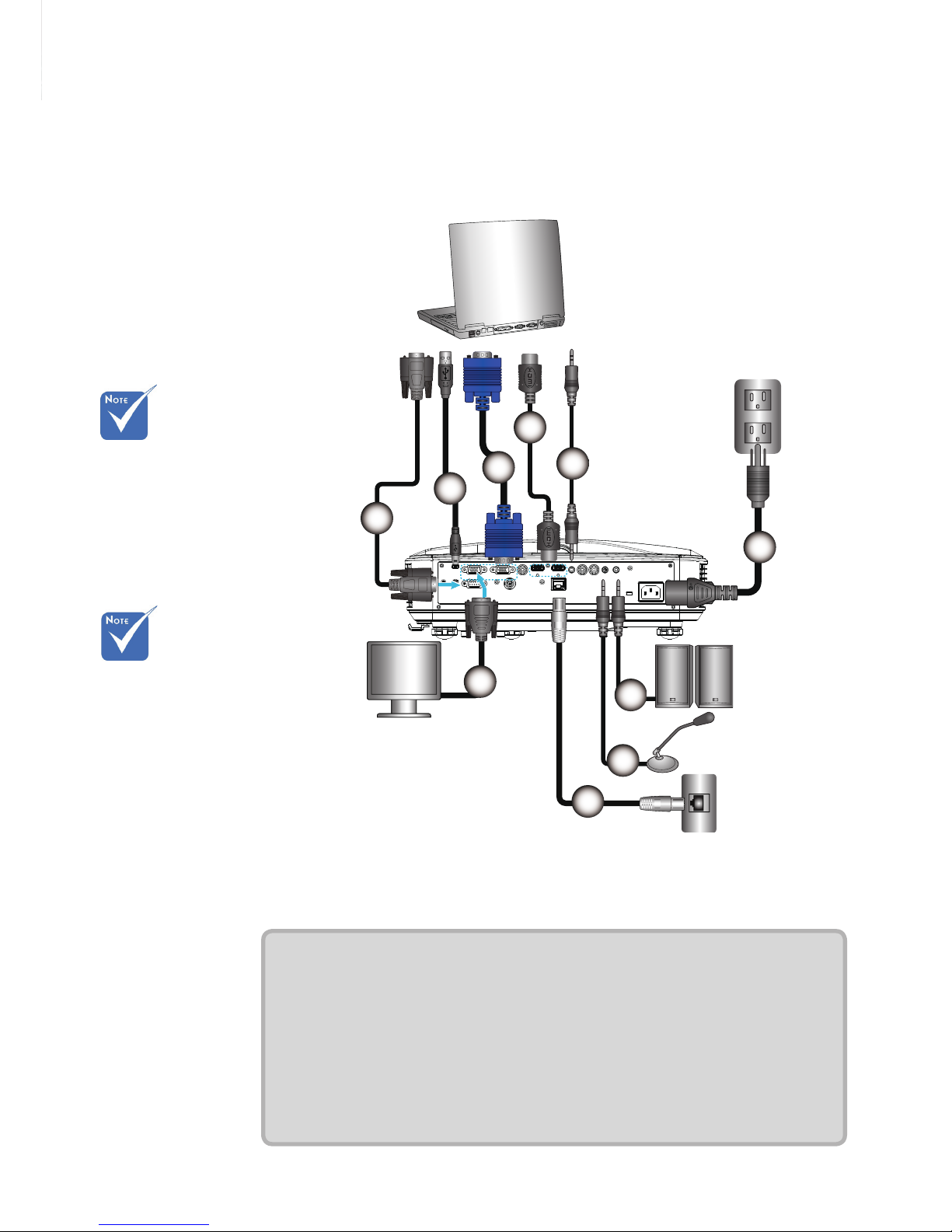
Installation
Connecting the Projector
Connect a Desktop/Laptop Computer
E62405SP
R
MOLEX
1
2
4
5
6
3
7
8
9
10
Due to applica-
tion discrepancies in different
countries/regions,
certain regions
may include different accessories
Remote keys vary
with projector
types.
1................................................................................................. RS232 Cable
2.....................................................................................................USB Cable
3.....................................................................................................VGA Cable
4................................................................................................... HDMI Cable
5.......................................................................................... Audio Input Cable
6.................................................................................................. Power Cable
7....................................................................................... Audio Output Cable
8.......................................................................................... Audio Input Cable
9....................................................................................................RJ45 Cable
10....................................................................................... VGA Output Cable
Router / Network Switch
Microphone
Audio Output
External
Display
Page 12
E62405SP
R
1
5
6
4
7
3
8
2
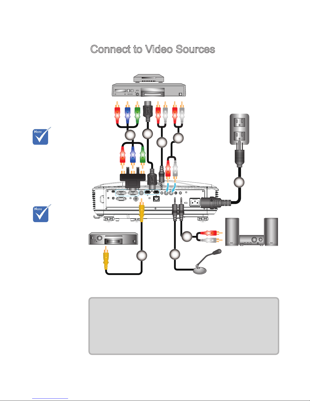
Connect to Video Sources
Due to
application
discrepancies in
different
countries/
regions, certain
regions may
include different
accessories.
Remote keys vary
with projector
types.
1................................................. 15-Pin to 3 RCA Component/HDTV Adapter
2................................................................................................... HDMI Cable
3...........................................................................................Audio Cable/RCA
4................................................................................................... Audio Cable
5.................................................................................................. Power Cable
6.................................................................................Composite Video Cable
7...........................................................................................Audio Cable/RCA
8.......................................................................................... Audio Input Cable
Composite Video Output
DVD player, STB (Set-top
Box), HDTV receiver
Microphone
Audio Output
Page 13
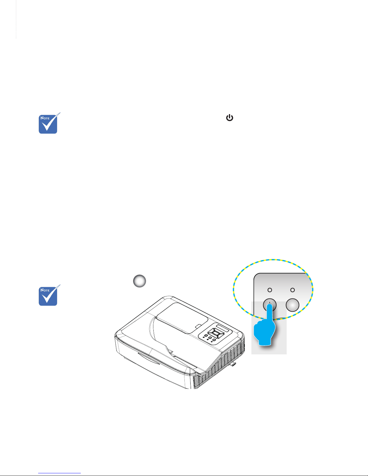
Powering the Projector On / Off
Turn on the
projector rst and
then select the
signal sources.
Powering On the Projector
1. Securely connect the power cord and signal cable. When
connected, the POWER/STANDBY LED will turn Red.
2. Turn the lamp on by pressing “ ” button either on the projec-
tor or on the remote. Once pressed, the POWER/STANDBY
LED will now turn Blue.
3. Turn on and connect the source that you want to display on
the screen (computer, notebook, video player, etc).
The projector will detect the source automatically. If not,
press menu button and go to “OPTIONS” to make sure “Auto
Source” is enabled.
If you connect multiple sources at the same time, press the
“INPUT” button on the control panel or direct source keys on
the remote control to switch between inputs.
When the projector
is in standby mode
(<0.5W), the VGA
output and the
transmitted audio
will be deactivated.
POWER/STANDBY
INPUTMENU
LAMPTEMP
ON(B)
STANDBY(R)
1
Page 14
Contact the
nearest service
center if the
projector displays
these symptoms.
When the warning indicators (see below) come on,
the projector will automatically shutdown:
“LAMP” LED indicator lights up in solid Red.
“TEMP” LED flashes Red. This indicates the projector has
overheated. Under normal conditions, the projector can be
switched back on.
Unplug the power cord from the projector, wait for 30 seconds
and try again. If the warning indicator lights up again, please
contact your nearest service center for assistance.
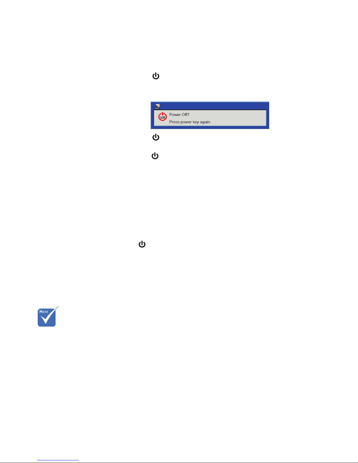
Powering Off the Projector
1. Press the “ ” button on the remote control or
on the control panel to turn the projector off.
The following message will be displayed on the screen.
Press the “ ” button again to confirm; otherwise the
message will disappear after 15 seconds. When you
press the “ ” button for the second time, the fan will
start cooling the system and the projector will shut down.
2. The cooling fans continue the cooling cycle for about 35
seconds and subsequently the POWER/STANDBY LED will
Flash Blue. When the POWER/STANDBY LED lights up
solid Red, the projector has entered standby mode.
If you wish to turn the projector back on, you must wait until
the projector has completed the cooling cycle and has
entered standby mode. Once in standby mode, simply
press “ ” button to restart the projector.
3. Disconnect the power cord from the electrical outlet and the
projector.
4. Do not turn the projector on immediately following a power
off procedure.
Warning Indicator
Page 15
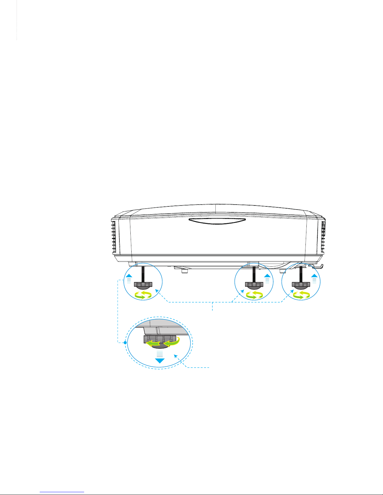
Adjusting the Projected Image
Adjusting the Projector’s Height
The projector is equipped with Adjustable feet for adjusting the image height.
1. Locate the adjustable feet you wish to modify on the
underside of the projector.
2. Rotate the adjustable ring clockwise to raise the projector
or counter clockwise to lower it. Repeat with the remaining
feet as needed.
Tilt-Adjustment Feet
Tilt-Adjustment Ring
Page 16
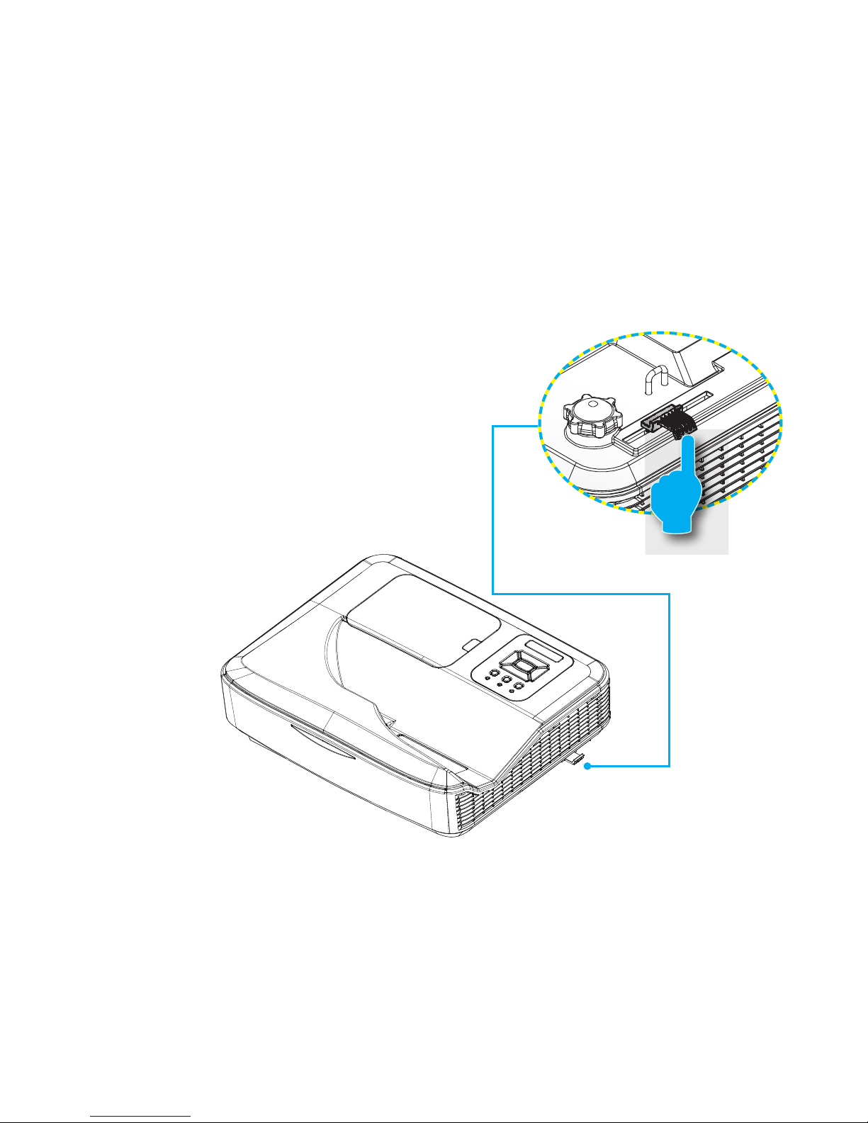
Adjusting the Projector’s Focus
To focus the image, slide the focus lever to left/right until the
image is clear.
WXGA series: The projector will focus at distances from
1.499 to 2.06 ft. (0.457 to 0.628 meter).
Focus Lever
Page 17
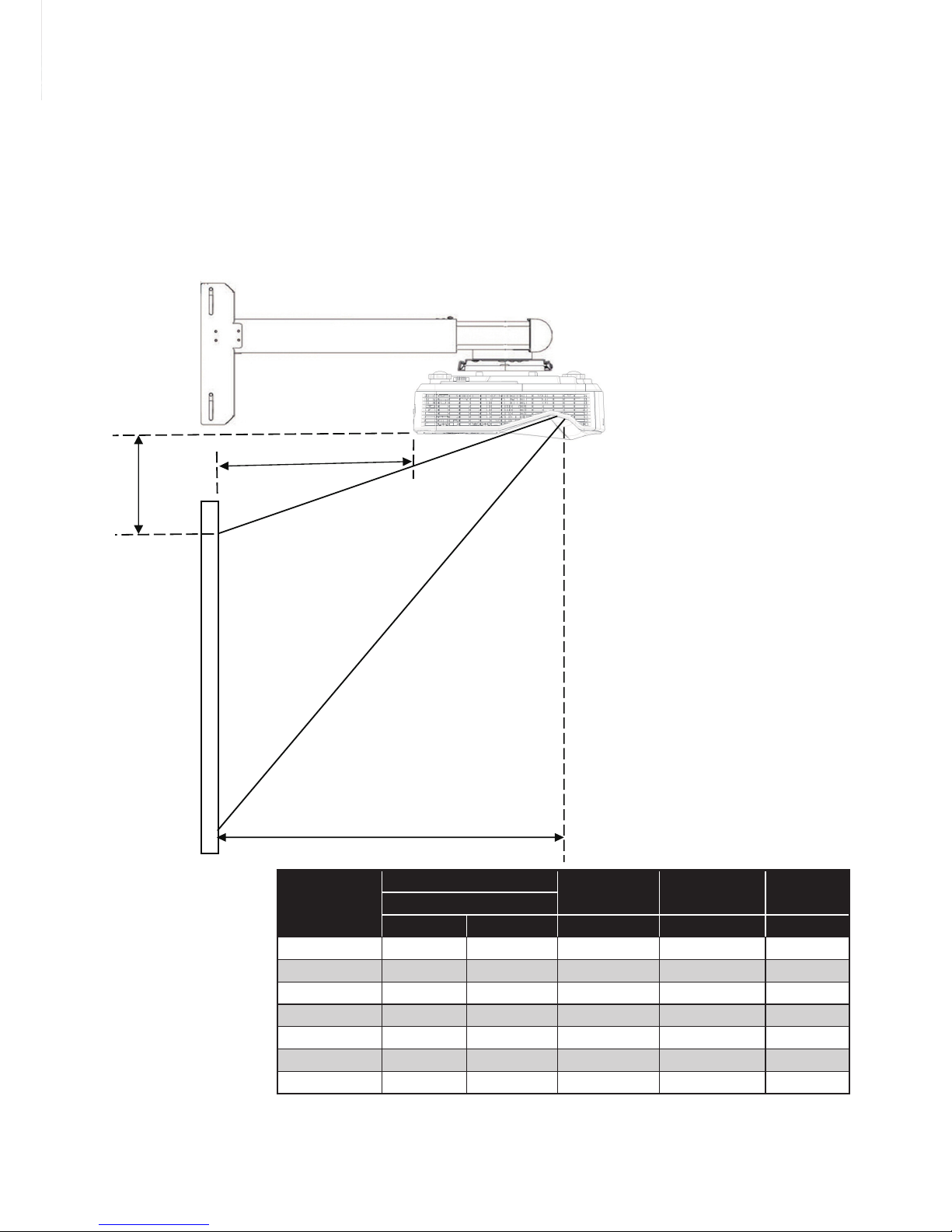
17
Adjusting Projection Image Size (Diagonal)
WXGA series: Projection Image Size from 80” to 110” (2.032
to 2.794 meters).
Diagonal of
Screen
Screen Size
Projection
Distance (D)
Projection
Distance (A)
V-Offset (B)
cm
W (Width) H (Height) cm cm cm
80 172.3 107.7 45.7 20.5 12
81 174.5 109 46.2 21.1 12.2
82 176.6 110.4 46.8 21.6 12.4
83 178.8 111 .7 47.4 22.2 12.6
84 180.9 113.1 47.9 22.8 12.8
85 183.1 114.4 48.5 23.3 13
86 185.2 115.8 49.1 23.9 13.2
B
A
D
D= Throw distance
B= Offset- 4.19cm
A= Throw distance – 25.17cm
D=Throw distance
B=Offset - 4.19cm
A=Throw distance - 25.17cm
Page 18
Diagonal of
Screen
Screen Size
Projection
Distance (D)
Projection
Distance (A)
V-Offset (B)
cm
W (Width) H (Height) cm cm cm
87 187.4 117.1 49.7 24.5 13.4
88 189.5 118.5 50.2 25.1 13.6
89 191.7 119.8 50.8 25.6 13.8
90 193.9 121.2 51.4 26.2 14
91 196 122.5 51.9 26.8 14.2
92 198.2 123.9 52.5 27.3 14.4
93 200.3 125.2 53.1 27.9 14.6
94 202.5 126.5 53.7 28.5 14.8
95 204.6 127.9 54.2 29.1 15
96 206.8 129.2 54.8 29.6 15.2
97 208.9 130.6 55.4 30.2 15.4
98 211.1 131.9 55.9 30.8 15.6
99 213.2 133.3 56.5 31.3 15.8
100 215.4 134.6 57.1 31.9 16
101 217.5 136 57.6 32.5 16.2
102 219.7 137.3 58.2 33.1 16.4
103 221.9 138.7 58.8 58.5 16.6
104 224 140 59.4 59.1 16.8
105 226.2 141.4 59.9 59.7 17
106 228.3 142.7 60.5 60.3 17.2
107 230.5 144 61.1 60.8 17.4
108 232.6 145.4 61.6 61.4 17.6
109 234.8 146.7 62.2 62 17.8
110 236.9 148.1 62.8 62.5 18
Page 19

User Controls
Control Panel
Control Panel & Remote Control
Using the Control Panel
POWER
Press “Power” to turn ON/OFF the projector.
Enter
Press “Enter” to conrm your selected item.
INPUT
Press “INPUT” to select signal source.
MENU
Press “MENU” to launch the on-screen display
(OSD) menu. To exit OSD, press “MENU” again.
Four Directional
Select Keys
Press
to select item.
LAMP LED
This indicates the lamp status of the projector.
TEMP LED
This indicates the lamp status of the projector.
ON/STANDBY
LED
This indicates the status of the projector.
Page 20

User Controls
Remote Control
Using the Remote Control
LED LED Indicator.
Power
Press Power to turn ON/OFF the
projector.
Exit Press “Exit” to close the OSD menu.
Zoom + Zoom in the display of the projector
Reset
Reset the adjustments to default setting.
Zoom - Zoom out the display of the projector.
Enter Conrm your selected item.
Input
Press “Source” to select an input
signal.
Auto
Automatically synchronizes the
projector to the input source.
Four Directional
Select Keys
Use
to select items or make
adjustments to your selection.
Keystone +/-
Adjust image keystone by tilting the
projector.
Volume +/- Adjust the Volume.
Aspect
Use this function to choose your desired aspect ratio.
Menu
Press “Menu” to launch the on-screen
display (OSD) menu. To exit OSD,
press “Menu” again.
VGA1
Press “VGA1” to choose VGA IN 1
connector.
Page 21

User Controls
Using the Remote Control
Blank screen
Momentarily turns off/on the audio and
video.
HDMI1
Press “HDMI1” to choose HDMI IN 1
connector.
HDMI2
Press “HDMI2” to choose HDMI IN 2
connector.
VGA2
Press “VGA2” to choose VGA IN 2
connector.
Video
Press “Video” to choose Composite
video source.
Freeze screen
Pause the screen image. Press again
to resume the screen image.
Image
Select the color mode from Bright, PC,
Movie, Game and User.
Page 22

User Controls
On-screen Display Menus
The Projector has multilingual On-screen Display menus that
allow you to make image adjustments and change a variety of
settings.
How to operate
1. To open the OSD menu, press “Menu” on the Remote Control or
Projector Keypad.
2 When OSD is displayed, use the
keys to select any item
in the main menu. While making a selection on a particular page,
press the
or “Enter” key to enter sub menu.
3. Use the keys to select the desired item and adjust the
settings using the
key.
4. Select the next item to be adjusted in the sub menu and adjust as
described above.
5. Press “Enter” to conrm, and the screen will return to the main
menu.
6. To exit, press “Menu” again. The OSD menu will close and the
projector will automatically save the new settings.
Main Menu
SettingsSub Menu
Page 23

User Controls
Picture
Color Mode
There are many factory presets optimized for various types of images. Use the ◄ or ► button to select the item.
Bright: For brightness optimization.
PC: For meeting presentation.
Movie: For playing video content.
Game: For game content.
User: Memorize user’s settings.
Wall Color
Use this function to obtain an optimized screen image according
to the wall color. You can select from “White”, “Light Yellow,” “Light
Blue,” “Pink,” and “Dark Green”.
Brightness
Adjust the brightness of the image.
Press the ◄ button to darken image.
Press the ► button to darken image.
Contrast
The Contrast controls the difference between the lightest and darkest parts of the picture. Adjusting the contrast changes the amount
of black and white in the image.
Press the ◄ button to decrease the contrast.
Press the ► button to increase the contrast.
Page 24

User Controls
Sharpness
Adjust the sharpness of the image.
Press the ◄ button to decrease the sharpness.
Press the ► button to increase the sharpness.
Saturation
Adjust a video image from black and white to fully saturated color.
Press the ◄ button to decrease the amount of saturation in the
image.
Press the ► button to increase the amount of saturation in the
image.
Hue
Adjust the color balance of red and green.
Press the ◄ button to increase the amount of green in the image.
Press the ► button to increase the amount of red in the image.
Gamma
This allows you to adjust the gamma value to obtain the better image contrast for the input.
“Sharpness”, “Sat-
uration” and “Hue”
functions are only
supported under
video mode.
Page 25

User Controls
Screen
Aspect Ratio
Auto: Keep the image with original width-height ratio and maximize the image to t native horizontal or vertical pixels.
4:3: The image will be scaled to t the screen and displayed
using a 4:3 ratio.
16:9: The image will be scaled to t the width of the screen and
the height adjusted to display the image using a 16:9 ratio.
16:10: The image will be scaled to t the width of the screen
and the height adjusted to display the image using a 16:10 ratio.
(only for SSI 1080p).
UWHD: The image will be scaled to t the width of the screen
and the height adjusted to display the image using a 16:6 ratio
(only for Ultrawide).
Phase
Synchronize the signal timing of the display with the graphic card.
If the image appears to be unstable or it
flickers, use this function
to correct it.
Clock
Adjust to achieve an optimal image when there is a vertical icker
in the image.
H. Position
Press the ◄ button to move the image left.
Press the ► button to move the image right.
“H. Position” and
“V. Position” rang-
es will depend on
input source.
Page 26

User Controls
V. Position
Press the ◄ button to move the image down.
Press the ► button to move the image up.
Digital Zoom
Press the ◄ button to reduce the size of an image.
Press the ► button to magnify an image on the projection
screen.
V Keystone
Press the ◄ or ► button to adjust image distortion vertically. If
the image looks trapezoidal, this option can help make the image
rectangular.
Ceiling Mount
Front: The image is projected straight on the screen.
Front Ceiling: This is the default selection. When selected, the
image will turn upside down.
Rear: When selected, the image will appear reversed.
Rear Ceiling: When selected, the image will appear reversed in
upside down position.
Page 27

User Controls
Setting
Language
Choose the multilingual OSD menu. Press the ◄ or ► button
into the sub menu and then use the ▲ or ▼ button to select your
preferred language. Press ► on the remote control to nalize the
selection.
Menu Location
Choose the menu location on the display screen.
Closed Caption
Use this function to enable closed caption menu. Select an
appropriate closed captions option: Off, CC1, CC2, CC3, and CC4.
VGA Output (Standby)
Choose “On” to enable VGA OUT connection.
Page 28

User Controls
LAN (Standby)
Choose “On” to enable LAN connection. Choose “Off” to disable
LAN connection.
VGA B (Function)
Input: Choose “Input” to let the VGA port work as a VGA input
function.
Output: Choose “Output” to enable the VGA Out function once
the projector is powered on.
Test Pattern
Display a test pattern.
Reset
Choose “Yes” to return the parameters on all menus to the factory
default settings.
Page 29

User Controls
Volume
Speaker
Choose “On” to enable the speaker.
Choose “Off” to disable the speaker.
Line Out
Choose “On” to enable the line out function.
Choose “Off” to disable the line out function.
Microphone
Choose “On” to enable the microphone.
Choose “Off” to disable the microphone.
Mute
Choose “On” to turn mute on.
Choose “Off” to turn mute off.
Volume
Press the ◄ button to decrease the volume.
Press the ► button to increase the volume.
Microphone Volume
Press the ◄ button to decrease the microphone volume.
Press the ► button to increase the microphone volume.
Page 30

User Controls
Options
Logo
Use this function to set the desired startup screen. If changes
are made, they will take effect the next time the projector is
powered on.
Default: The default startup screen.
User: Use stored picture from “Logo Capture” function.
Logo Capture
Press ► button to capture an image of the picture currently displayed on screen.
Auto Source
On: The projector will search for other signals if the current input
signal is lost.
Off: The projector will only search current input connection.
Input
Press ► button to enable/disable input sources. The projector will
not search for inputs that are not selected.
For successful logo
capture, please
ensure that the onscreen image does
not exceed the
projector’s native
resolution.
(WXGA:1280x800).
“Logo Capture” is
not available when
3D is enabled.
Before activating
this function, it is
recommended that
“Aspect Ratio” is
set to the “Auto.”
Page 31

User Controls
Auto Power Off (Min)
Sets the countdown timer interval. The countdown timer will start
when there is no signal being sent to the projector. The projector
will automatically power off when the countdown has nished (in
minutes).
Lamp Settings
Refer to page 32.
High Altitude
On: The built-in fans run at high speed. Select this option when
using the projector at altitudes above 2500 feet/762 meters or
higher.
Off: The built-in fans automatically run at a variable speed according to the internal temperature.
Filters Remind (Hour)
Filters Remind (Hour): Set the lter reminder time.
Cleaning Up Remind: Select “Yes” to reset the dust lter hour
counter after replacing or cleaning the dust lter.
Information
Display the projector information for model name, SNID, source,
resolution, software version, and aspect ratio on the screen.
“Dynamic Black”
is available when
“Color Mode” is
set to “Movie”.
“Dynamic Black”
is not available
when “3D” or
“Interactive” is
enabled.
When “Dynamic
Black” is available, “Lamp
Power Mode”
selection is not
available.
Page 32

User Controls
Options |
Lamp Settings
Lamp Hours Used (Normal)
Display the projection time of normal mode.
Lamp Hours Used (ECO)
Display the projection time of ECO mode.
Lamp Power Mode
Normal: Normal mode.
ECO: Use this function to dim the projector lamp which will
lower power consumption and extend the lamp life.
Clear Lamp Hours
Choose “Yes” to reset the lamp hour counter.
Page 33

User Controls
3D
3D
Auto: When an HDMI 1.4a 3D timing identification signal is de-
tected, the 3D image is selected automatically.
Choose “On” to enable 3D function.
Choose “Off” to disable 3D function.
3D Invert
If you see a discrete or overlapping image while wearing DLP 3D
glasses, you may need to execute “Invert” to get best match of left/
right image sequence to get the correct image.
3D Format
Use this feature to select the 3D format. Options are: “Frame
Packing,” “Side-by-Side (Half),” “Top and Bottom,” “Frame
Sequential,” and “Field Sequential.”
1080p@24
Use this feature to select 96 or 144Hz refresh rate as using 3D
glasses in the1080p @ 24 frame packing.
“Frame Sequen-
tial” is supported
by the DLP Link 3D
input signals from
VGA /HDMI
connector.
“Frame Sequen-
tial” / “Field Sequential” are sup-
ported by the
HQFS 3D input
signals from
Composite/
S-Video connector
connector.
“Frame Packing” /
“Side-bySide(Half)” / “Top
and Bottom” are
supported from
HDMI 1.4a 3D
input signals.
Page 34

User Controls
Interactive
Interactive Settings
Choose “On” to enable Interactive function.
Choose “Off” to disable Interactive function.
You need to unplug the Mini USB cable that connects NB/desktop
with the projector before using the Interactive function. After you
complete the Interactive Settings in OSD, use Mini USB cable to
connect NB/desktop to the projector.
The Interac-
tive function is
available when
displaying graphic
source from HDMI/
VGA input. Other
sources are not
supported.
If “3D” or “Dynamic
Black” function is
enabled, “Interactive” feature is
disabled.
Interaction function:
Please specify that
the Interaction
function is only for
USTi model. The
Interaction function
is not available in
the UST model.
Page 35

User Controls
LAN
Status
Display the network connection status.
DHCP
Congure the DHCP settings.
On: Choose “On” to let the projector obtain an IP address
automatically from your network.
Off: Choose “Off” to assign IP, Subnet Mask, Gateway, and DNS
configuration manually.
IP Address
Display an IP address.
Subnet Mask
Display the subnet mask number.
Gateway
Display the default gateway of the network connected to the pro-
jector.
DNS
Display the DNS number.
MAC Address
Display the MAC address.
Page 36

User Controls
Group Name
Display the group name.
Projector Name
Display the projector name.
Location
Display the projector location.
Contact
Display the contact information.
Page 37

User Controls
How to use web browser to control your projector
1. Turn on DHCP to allow a DHCP
server to automatically assign an IP, or
manually enter the required network
information.
2. Then choose apply and press
button to complete the conguration
process.
3. Open your web browser and type in IP
Address from the OSD LAN screen then
the web page will display as below:
4. Based on network web-page for the
input-string in [tools] tab, the limitation
for Input-Length is in the below list
(“space” and the other punctuation
keys included):
Category Item
Input-Length
(characters)
Crestron Control
IP Address 15
IP ID 2
Port 5
Projector
Projector Name 10
Location 9
Assigned To 9
Network
Conguration
DHCP (Enabled) (N/A)
IP Address 15
Subnet Mask 15
Default Gateway 15
DNS Server 15
User Password
Enabled (N/A)
New Password 15
Conrm 15
Admin Password
Enabled (N/A)
New Password 15
Conrm 15
When you use the projector IP
address, you can't link to your
service server.
Page 38

User Controls
When making a direct connection from your computer to the projector
Step 1: Find an IP Address (192.168.0.100) from LAN function of projector.
Step 2: Select apply and press “Enter” button to submit function or press “menu” key to
exit.
Step 5: Click Use the following IP
address, and type in as below:
1) IP address: 192.168.0.100
2) Subnet mask: 255.255.255.0
3) Default gateway:192.168.0.254
Step 6: To open Internet Options, click IE
web browser, click Internet Options,
click the Connections tab and click
“LAN Settings...”.
Step 7: The Local Area Network (LAN)
Setting dialog box appears. In the
Proxy Server area, cancel the
Use a proxy server for your LAN
check box, then click “OK” button
twice.
Step 8: Open your IE and type in the IP
address of 192.168.0.100 in the
URL then press “Enter” key.
Step 3: To open Network Connections,
click Start, click Control Panel,
click Network and Internet
Connections, and then click
Network Connections. Click the
connection you want to congure,
and then, under Network Tasks
, click Change settings of this
connection.
Step 4: On the General tab, under
This connection uses the
following items, click Internet
Protocol (TCP/IP), and then click
“Properties.”
Page 39

User Controls
Crestron RoomView Control Tool
Crestron RoomView™ provides a central monitoring station for 250
+ control systems on a single Ethernet network (more are possible-
the number depends on the combination of IP ID and IP address).
Crestron RoomView monitors each projector, including projector’s
online status, system power, lamp life, network setting and hardware
faults, plus any custom attribute as dened by the Administrator.
The Administrator can add, delete, or edit room information, contact
information and events, which are logged automatically by the
software for all users. (Operation UI as following image)
1. Main Screen
2. Edit Room
Page 40

User Controls
3. Edit Attribute
4. Edit Event
For further information, please visit:
http://www.crestron.com & www.crestron.com/getroomview.
Page 41

Appendices
Replace the Lamp
This projector will automatically detect the service life of its lamp.
When service life of the lamp is about to expire, a warning message
will be displayed.
When you see this message, please contact the local dealer or
service center to replace the lamp as soon as possible. Please be
sure that the projector has been cooled down for at least 30 minutes
before replacement of the lamp.
Warning: If the projector is installed on the ceiling, please
handle carefully when you open the lamp cover. If the
projector is installed on the ceiling, we suggest that you
wear safety glasses when replacing the lamp. “Always
handle carefully to prevent any loose component from
falling off the projector.”
Warning: The lamp Component may be hot! Replace the
lamp after it is cooled down!
Warning: To reduce the risk of personal injury, please
prevent the lamp module from falling down and avoid
touching the lamp. If the lamp falls down, it may be broken
up, which may cause injury.
Page 42

Appendices
The screws on
the latern and the
lamp shall not be
removed.
If the lamp cover is
not reinstalled on
the projector yet,
the projector cannot
be switched on.
Do not touch the
glass area of the
lamp. Oil on hands
may cause the lamp
to break up. If you
accidentally touch
the lamp module,
please clean it with
dry cloth.
1. Press “ ” button to power the projector off.
2. Cool down the projector for at least 30 minutes.
3. Pull off the power cable.
4.
Press the release button and pull up the lamp cover of the main components. 1
5. Lift up and remove the lamp cover. 2
6. Remove the 2 screws on the lamp module. 3
7.
Pull up the Lamp Handle 4 and pull the lamp module out carefully and slowly. 5
Follow the aforesaid steps in the reverse order to install the lamp module.
8. After the lamp module is replaced, switch on the projector and reset the lamp
hour counter.
(i) Press to open the “Service” menu.
(ii) Select “Reset Lamp Hours”.
1
2
3
4
5
Page 43

Appendices
Installing and Cleaning the Optional
Dust Filter
operation, or more often if you are using the projector in a
dusty environment.
When the warning message appears on the screen, do the
The optional dust
used in dusty
environments.
installed, a proper
maintenance will
prevent overheating and projector
malfunction.
Air Filter Cleaning Procedure:
1. Turn off the projector.
2. Disconnect the power cord.
3.
illustration.
1
4.
2
5.
replaced.
1
1
2
2
Page 44

Appendices
Compatibility Modes
VGA Analog
a. PC Signal
Modes Resolution
V.Frequency
[Hz]
H.Frequency
[KHz]
VGA
640x480 60 31.5
640x480 67 35
640x480 72 37.9
640x480 75 37.5
640x480 85 43.3
IBM 720x400 70 31.5
SVGA
800x600 56 35.1
800x600 60 37.9
800x600 72 48.1
800x600 75 46.9
800x600 85 53.7
800x600 120 77.4
Apple, Mac II 832x624 75 49.1
XGA
1024x768 60 48.4
1024x768 70 56.5
1024x768 75 60
1024x768 85 68.7
1024x768 120 99
Apple, Mac II 1152x870 75 68.7
SXGA
1280x1024 60 64
1280x1024 72 77
1280x1024 75 80
QuadVGA
1280x960 60 60
1280x960 75 75.2
SXGA+ 1400x1050 60 65.3
UXGA 1600x1200 60 75
Page 45

Appendices
b. Extended Wide timing
Modes Resolution
V.Frequency
[Hz]
H.Frequency
[KHz]
WXGA
1280x720 60 44.8
1280x720 120 92.9
1280x800 60 49.6
1366x768 60 47.7
1440x900 60 59.9
WSXGA+ 1680x1050 60 65.3
c. Component Signal
Modes Resolution
V.Frequency
[Hz]
H.Frequency
[KHz]
480i
720x480
(1440x480)
59.94(29.97) 15.7
576i
720x576
(1440x576)
50(25) 15.6
480p 720x480 59.94 31.5
576p 720x576 50 31.3
720p 1280x720 60 45
720p 1280x720 50 37.5
1080i 1920x1080 60(30) 33.8
1080i 1920x1080 50(25) 28.1
1080p 1920x1080 23.98/24 27
1080p 1920x1080 60 67.5
1080p 1920x1080 50 56.3
HDMI Digital
a. PC Signal
Modes Resolution
V.Frequency
[Hz]
H.Frequency
[KHz]
VGA
640x480 60 31.5
640x480 67 35
640x480 72 37.9
640x480 75 37.5
640x480 85 43.3
Page 46

Appendices
IBM 720x400 70 31.5
SVGA
800x600 56 35.1
800x600 60 37.9
800x600 72 48.1
800x600 75 46.9
800x600 85 53.7
800x600 120 77.4
Apple, Mac II 832x624 75 49.1
XGA
1024x768 60 48.4
1024x768 70 56.5
1024x768 75 60
1024x768 85 68.7
1024x768 120 99
Apple, Mac II 1152x870 75 68.7
SXGA
1280x1024 60 64
1280x1024 72 77
1280x1024 75 80
QuadVGA
1280x960 60 60
1280x960 75 75.2
SXGA+ 1400x1050 60 65.3
UXGA 1600x1200 60 75
Page 47

Appendices
b. Extended Wide timing
Modes Resolution
V.Frequency
[Hz]
H.Frequency
[KHz]
WXGA
1280x720 60 44.8
1280x720 120 92.9
1280x800 60 49.6
1366x768 60 47.7
1440x900 60 59.9
WSXGA+ 1680x1050 60 65.3
c. HDMI - Video Signal
Modes Resolution
V.Frequency
[Hz]
H.Frequency
[KHz]
640x480p 640x480 59.94/60 31.5
480i
720x480
(1440x480)
59.94(29.97) 15.7
576i
720x576
(1440x576)
50(25) 15.6
480p 720x480 59.94 31.5
576p 720x576 50 31.3
720p 1280x720 60 45
720p 1280x720 50 37.5
1080i 1920x1080 60(30) 33.8
1080i 1920x1080 50(25) 28.1
1080p 1920x1080 23.98/24 27
1080p 1920x1080 60 67.5
1080p 1920x1080 50 56.3
d. HDMI 1.4a mandatory 3D timing- Video Signal
Modes Resolution
V.Frequency
[Hz]
H.Frequency
[KHz]
Frame
Packing
720p 50
720p 59.94/60
1080p 23.98/24
Side-by-Side
1080i 50
1080i 59.94/60
Top-and-
Bottom
720p 50
720p 59.94/60
1080p 23.98/24
Page 48

Appendices
List of specications
Item Specication
Resolution WXGA
Graphics Card DMD Dimensions 0.65”
Projector Technology DLP
Projector Lens Fixed Lens, f/2.4
Lighting Technology Philips Smart Energy-Saving Lamp
Brightness 4000 Lumens
Contrast 10000:1 (High Contrast Ratio mode)
Supported resolution Up to 1080p @ 60Hz (CEA 861)
Throw Ratio 0.27
Weight (KG) 4.5KG
Dimensions 383mm(W) x 310mm(D) x 103mm(H) (excluding foot)
Light Power 260W
Light Life 3000 Hours / 4000 Hours (ECO Mode)
Total Power (W) 320W
Standby Power (W) <0.5W
Audio Output 16W
Operating Noise 34dB / 29dB (ECO Mode)
Input Terminals
VGA and Y/Pb/Pr X1: D-sub female 15 pin terminal (blue)
HDMI
X2: Standard HDMI terminal
1)Support HDMI input with HDMI 1.4a compliant.
2)Supports High bandwidth Digital Content Protection
– HDCP Standard 1.3 of December 2006
VGA Audio X1: Stereo mini jack
MIC X1: Stereo mini jack
Composite Video X1: RCA (yellow)
Composite Audio X2: RCA for both left and right
Output Terminals
Audio X1: Stereo mini jack(green)
VGA
X1: D-sub female 15 pin terminal (black)
(Support VGA in function)
Page 49

Appendices
Other Terminals
Mini USB-B Mini USB type B (for FW download)
RS232 DB9 Male terminal
RJ45 RJ45 for LAN control
Page 50

Appendices
Please note that
damage resulting
from incorrect
installation will void
the warranty.
Wall Mount Installation
If you wish to use a third party ceiling mount kit, please
ensure the screws used to attach a mount to the projector
meet the following specifications:
Screw type: M4*4
Minimum screw length: 10mm
Warning:
1. If you buy a ceiling
mount from another
company, please
be sure to use the
correct screw size.
Screw size will vary
depending on the
thickness of the
mounting plate.
2. Be sure to keep
at least 10 cm gap
between the ceiling
and the bottom of the
projector.
3. Avoid installing the
projector near a heat
source.
Unit: mm
126.26
88.00
130.00
382.44
310.18
Page 51

Appendices
Regulation & Safety Notices
This appendix lists the general notices of your projector.
FCC notice
This device has been tested and found to comply with the
limits for a Class B digital device pursuant to Part 15 of the
FCC rules. These limits are designed to provide reasonable
protection against harmful interference in a residential
installation. This device generates, uses and can radiate radio
frequency energy and, if not installed and used in accordance
with the instructions, may cause harmful interference to radio
communications.
However, there is no guarantee that interference will not
occur in a particular installation. If this device does cause
harmful interference to radio or television reception, which can
be determined by turning the device off and on, the user is
encouraged to try to correct the interference by one or more of
the following measures:
• Reorient or relocate the receiving antenna.
• Increase the separation between the device and receiver.
• Connect the device into an outlet on a circuit different
from that to which the receiver is connected.
• Consult the dealer or an experienced radio/television
technician for help.
Notice: Shielded cables
All connections to other computing devices must be
made using shielded cables to maintain compliance with
FCC regulations.
Caution
Changes or modications not expressly approved by the
manufacturer could void the user’s authority, which is
granted by the Federal Communications Commission, to
operate this projector.
Page 52

Appendices
Disposal instructions
Do not throw this electronic device into the
trash when discarding. To minimize pollution
and ensure utmost protection of the global
environment, please recycle it.
Operation conditions
This device complies with Part 15 of the FCC Rules. Operation
is subject to the following two conditions:
1. This device may not cause harmful interference and
2. This device must accept any interference received,
including interference that may cause undesired
operation.
Notice: Canadian users
This Class B digital apparatus complies with Canadian
ICES-003.
Remarque à l’intention des utilisateurs
canadiens
Cet appareil numerique de la classe B est conforme a la
norme NMB-003 du Canada.
Declaration of Conformity for EU
countries
• EMC Directive 2004/108/EC (including amendments)
• Low Voltage Directive 2006/95/EC
• R & TTE Directive 1999/5/EC (if product has RF function)
Page 53

Appendices
Appendices
- This projector is a Class 1 laser device that conforms
with IEC 60825-1:2014, CFR 1040.10 and 1040.11,
IEC 62471 Low Risk Group 1
- This projector has built-in Class 4 laser module. Disassembly
or modification is very dangerous and should never be
attempted.
- Any operation or adjustment not specifically instructed by the
user’s guide creates the risk of hazardous laser radiation
exposure.
- Do not open or disassemble the projector as this may cause
damage by the exposure of laser radiation.
- Do not stare into beam when the projector is on. The bright
light may result in permanent eye damage.
- Without following the control, adjustment, or operation
procedure may cause damage by the exposure of laser
radiation.
- Adequate instructions for assembly, operation, and
maintenance, including clear warnings concerning precautions
to avoid possible exposure to laser and collateral radiation in
excess of the accessible emission limits in Class 1.
CAUTION:
CLASS 4 LASER RADIATION
WHEN OPEN AND INTERLOCKS
DEFEATED AVOID EYE OR SKIN
EXPOSURE TO DIRECT OR
SCATTERED RADIATION .
IEC60825-1:2014.
Complies with IEC 62471 Low Risk
Group 1
CLASS1LASERPRODUCT
IEC60825-1:2014.
Complies with IEC 62471 Low Risk Group 1
Safety notice
Page 54

Page 1
Mimio/BOXLIGHT Warranty Historical Reference
BACKGROUND
This document contains the BOXLIGHT and Mimio warranty statements as of April 15, 2016 which were
superseded by the revised and unified warranty whose effective date is proposed to be June 1, 2016.
It should be noted that BOXLIGHT had at least two warranty statements and these two conflicted in some
areas.
The Mimio warranty would certainly win some prize for brevity, though not for clarity or completeness.
Page 55

Page 2
BOXLIGHT Warranties as of April 15, 2016
Standard Projector Warranty:
All BOXLIGHT projectors come with a three-year parts and labor warranty. BOXLIGHT warrants the products
manufactured by BOXLIGHT are free from defects in materials and workmanship under normal use during the term of
the warranty. The warranty covers parts and labor only, and does not include lamps or accessories.
Standard Lamp Warranty:
BOXLIGHT Inc. warranties lamps for 90 days or 500 hours, whichever comes first, from date of original shipment
from BOXLIGHT Inc., or proof presented of shipment from dealer showing tracking information with weight or packing
slip presented. This applies to lamp sales either as part of a projector, or sold separately.
Projector Extended Warranty:
BOXLIGHT Extended Warranty gives you peace of mind by extending the original warranty for an additional 1, 2, or 3
years. The warranty covers parts and labor only, and does not include lamps or accessories.
1 year (4 year total) extended projector warranty $229 MSRP
2 year (5 year total) extended projector warranty $359 MSRP
3 year (6 year total) extended projector warranty $499 MSRP
Extended Lamp Warranty:
BOXLIGHT’s Lamp Warranty extends the standard 90 day (or 500 hours warranty) to 1, 2 or 3 years depending on
Lamp Warranty purchased. Customer is limited to a maximum of two (2) lamp replacements during the contract
period. BOXLIGHT may require a unit to be sent in for repair or evaluation when multiple lamp claims are exercised
within a shortened period. The warranty covers projector lamps and any possible defective parts causing premature
lamp failure.
1 year extended lamp warranty $225 MSRP
2 year extended lamp warranty $275 MSRP
3 year extended lamp warranty $350 MSRP
Product Warranty Statement
LAMPS for LIFE:
"LAMPS for LIFE Warranty Program" provides a free replacement lamp for the life of the projector. Customer must
send in failed lamp in order to receive replacement lamp. Customer is responsible for the shipping cost to and from.
Prior to exchange of third lamp within "LAMPS for LIFE," BOXLIGHT may require an evaluation of your projector.
This is to ensure premature failure is not a result of any other failed component and to provide any necessary
cleaning of your equipment.
Excessive lamp use of more than 12 hours a day will void "LAMPS for LIFE" warranty. If projector is used in a smoke
filled or other high pollutant environment, the projector must be equipped and operated with a harsh environment filter
to be eligible for "LAMPS for LIFE." Terms and conditions state the lamp filter must be changed every 6 months and
cleaned as necessary based on operating environment, end user must follow all other maintenance and operating
procedures. Any lamp failure caused by accident, abuse, or failure to follow all maintenance and operating conditions
Page 56

Page 3
is not covered under "LAMPS for LIFE." During the first 90 days of purchase of projector or purchase of new lamp,
lamp is covered under Standard Lamp Warranty. "LAMPS for LIFE" is subject to all terms, limitations and exclusions
set forth in the limited warranty statement for the associated product.
Lamps for Life web page
Lamps for Life - Education
Page 57

Page 4
Lamps for Life - Corporate
Lamps for Life information
Lamps for Life FAQ
Lamps for life page
Lamps for Life for education
Lamps for Life for Corporate
Flat Panel Warranty:
BOXLIGHT, Inc., ("Provider") is pleased to offer a standard three(3) year limited manufacturer's warranty ("Limited
Warranty") against malfunction due to manufacturing defects in materials or workmanship on our hardware and
accessories. The Limited Warranty applies only if: (1) the Provider Products are installed according to Provider's
instruction provided to Customer and (2) the Provider Products are not misused or abused, and there is no evidence
of mishandling, neglect, modification or repair without the approval of Provider, or damage done to Provider's
Products by anyone other than Provider. The following is not included under this Limited Warranty: (1) Misuse or
abuse by the Customer; (2) normal wear and tear; and (3) physical damage to Provider's Products as a result of
unreasonable use and/or negligence. This Limited Warranty is provided by Provider, and it contains the only express
warranty provided to Customer by Provider. Provider does not authorize any other person, including distributors, to
give any other warranties on Provider's behalf. The repair or replacement as provided under the express limited
warranty is the sole and exclusive remedy of the Customer and Provider's sole and exclusive liability hereunder.
Provider disclaims any express warranty not provided herein and any implied warranty, guaranty or representation as
to performance, quality and absence of hidden defects, and any remedy for breach of contract, which but for this
provision, might arise by implication, operation of law, custom of trade or course of dealing, including implied
warranties of merchantability and fitness for a particular purpose. In no event shall Provider be liable, whether in
contract, tort (including negligence) or otherwise, for damages in excess of the purchase price of the product giving
rise to the damages, or for any direct, indirect, incidental, special, punitive, exemplary, or consequential damages of
any kind. Provider further disclaims any responsibility for losses, expenses, inconveniences, special, indirect,
secondary, or consequential, incidental, and contingent damages whatsoever, including damages arising from
ownership or use of provider's products. Provider shall bear no responsibility or obligation with respect to the manner
of use of any equipment sold by Provider. Provider specifically disclaims and negates any warranty of fitness for a
particular purpose of such equipment including, without limitation, any warranty that the use of such equipment for
any purpose will comply with applicable laws and regulations or overcome any specific hearing/auditory processing
deficit. When returning units for service, use adequate packaging to prevent shipping damage. Shipping damage is
not covered under warranty. If during standard troubleshooting Provider Support determines the ProColor Panel
Page 58

Page 5
cannot be fixed via phone, Provider will provide a replacement panel of equal or better quality that will be shipped
within 48 to 72 hours from the time of the reported failure unless other contractual arrangements have been made
directly with Boxlight. All replacement ProColor Panels will ship via standard 3 to 5 day ground freight service, paid by
Provider. The customer is responsible for all costs associated with removal and packaging of the defective panel and
the installation of the replacement panel. The defective panel must be ready for return shipment within 10 days of
receipt of the replacement panel. Provider will then arrange for the pickup and return shipping of the defective panel.
If Provider is not notified that the defective panel is ready for return shipment the customer will be responsible for the
return cost of the defective panel, and if it is not received within 30 days customer will be responsible for the full cost
of the replacement panel and the defective panel.
Page 59

Page 6
The “Other” BOXLIGHT Warranty
From (note NetSuite URL showing up – red color added for visibility):
https://system.netsuite.com/core/media/media.nl?id=211327&c=492114&h=b337ff4ec39bcec928c6&_xt=.
pdf&ck=SF3TEWglAoxPTd66&vid=SF3TEWglAo1PTaTa&cktime=140623&addrcountry=US
LIMITED WARRANTY BOXLIGHT Incorporated ("BOXLIGHT") warrants that each BOXLIGHT projector
and BOXLIGHT interactive flat panel ("the Product") sold hereunder will conform to and function in
accordance with the written specifications of BOXLIGHT. Said limited warranty shall apply only to the first
person or entity that purchases the Product for personal or business use. Said warranty shall continue for
a period of five (5) years for projectors and three (3) years for interactive flat panels, when the product is
purchased from a Premier Partner. All others receive a three (3) years warranty on projectors and two (2)
year warranty on interactive flat panels. All warranties commence on the date of purchase and are Parts
and Labor only. BOXLIGHT does not warrant that the Product will meet the specific requirements of the
first person or entity that purchases the Product for personal or business use. Lamp is warrantied for 90
days or 500 hours (whichever comes first). Accessories are warrantied for 1 year from date of purchase
and include all product accessories that are not a projector or panel. BOXLIGHT liability for the breach of
the foregoing limited warranty is limited to the repair or replacement of the Product, at BOXLIGHT's sole
option. To exercise the Purchaser's rights under the foregoing warranty, projector must be returned to
BOXLIGHT at Purchaser’s sole cost and expense. BOXLIGHT will pay for return shipping to customer.
Warranty service for Interactive Flat Panels shipping shall be covered to and from BOXLIGHT or an
authorized service center. However, that the Product must be accompanied by a written letter explaining
the problem and which includes (i) proof of purchase; (ii) the dealer's name; and (iii) the model and serial
number of the Product. A return authorization number, issued by the BOXLIGHT customer service
department, must also be clearly displayed on the outside of the shipping carton containing the Product,
or shipment will be refused. WARRANTY LIMITATION AND EXCLUSION BOXLIGHT Incorporated shall
have no further obligation under the foregoing limited warranty if the Product has been damaged due to
abuse, misuse, neglect, accident, unusual physical or electrical stress (unusual physical and electrical
stress includes unusually long operation, exposure to smoke and other airborne contaminants),
unauthorized modification, tampering, alterations, or service other than by BOXLIGHT or its authorized
agents, causes other than from ordinary use or failure to properly use the Product in the application for
which said Product is intended. DISCLAIMER OR UNSTATED WARRANTIES The warranty printed
above is the only warranty applicable to this purchase. All other warranties express or implied, including,
but not limited to, the implied warranties or merchantability and fitness for a particular purpose are
disclaimed. There are no warranties that extend beyond the face hereof and the foregoing warranty shall
not be extended, altered or varied except by written instrument signed by BOXLIGHT Incorporated. It is
understood and agreed that BOXLIGHT's liability whether in contract, in tort, under any warranty, in
negligence or otherwise shall not exceed the return of the amount of the purchase price paid by
purchaser and under no circumstances shall BOXLIGHT be liable for special, indirect or consequential
damages. The price stated for the Product is a consideration in limiting BOXLIGHT's liability. No action
regardless of form, arising out of the agreement to purchase the product may be brought by purchaser
more than one year after the cause of action has accrued. FOR MORE INFORMATION, CONTACT:
BOXLIGHT Incorporated PO Box 2609 151 State Highway 300, Suite A Belfair, WA 98528
www.boxlight.com U.S. and Canada 360.464.2119
Page 60

Page 7
The Mimio Warranty
Mimio warrants all our hardware (excluding batteries and the MimioProjector™ bulb) to be free of defects
and to perform as specified under normal classroom conditions for a period of 2 years from purchase.
The 2-year product warranty can be extended for all hardware except the MimioProjector interactive
projector and the MimioDisplay™ touch display for an additional 3 years, with registration online at
mimio.com/registration within 90 days of product receipt date. The MimioProjector bulb is guaranteed for
90 days. The rechargeable batteries provided with MimioVote™ handsets are under warranty for a period
of 2 years from the date of purchase. A replacement pack is available for purchase. MimioStudio™
software is supplied with a limited lifetime warranty, expiring 1 year after discontinuation of product, to
perform as specified with the computer operating systems supported in the product specification.
= = = = END = = = = =
 Loading...