

Page 1

Bovie Medical Corporation Page: 1 of 28
Document Number: QA-256 Effective Date: 1/12/12
Revision No: 23
Title: TESTING PROCEDURE FOR THE IDS-SERIES ELECTROSURGICAL UNIT
1.0 PURPOSE:
To describe the procedure for testing of the IDS-Series Electrosurgical Unit
2.0 SCOPE:
This procedure applies to the set-up, calibration, and operational testing for the IDS-Series Electrosurgical Unit.
3.0 RESPONSIBILITIES:
3.1 The testing of the Electrosurgical Unit is performed by trained test and integration technicians
3.2 Final review of packaging and the Device History Record is performed by trained Quality Assurance personnel
4.0 RELATED DOCUMENTS:
5.0
5.0
4.1 Device History Record (DHR) for the IDS-Series of ESU’s (DOC-472)
4.2 Work Instruction for Final Assembly of the IDS-Series of ESU’s (WI-0368)
4.3 Electrostatic Discharge (ESD) Protection Procedure (WI-0224)
4.4 Control of Non-Conforming Materials (QA-080)
4.5 IDS series Factory Presets (DOC-476)
4.6 ESU Failure Codes (WI-0388)
4.7 IDS Series Final Assembly Router (DOC-602)
4.8 ESU Packout WI-387
EQUIPMENT:
EQUIPMENT:
(NOTE: RECORD ON DHR THE ID/FIXTURE # OF ALL EQUIPMENT USED)
(NOTE: RECORD ON DHR THE ID/FIXTURE # OF ALL EQUIPMENT USED)
5.1 FM Power Meter or Metron QA-ES Electrosurgical Analyzer
5.2 Oscilloscope
5.3 Oscilloscope Probe 1000x
5.4 Dielectric (Hipot) Tester
5.5 Safety Analyzer
5.6 Standard Technicians Tool Kit
5.7 Miscellaneous Test Leads and Cables
5.8 Burn-In Racks with load fixtures (F-262)
5.9 2-button Handpiece
5.10 2-Pedal Monopolar Footswitch
5.11 Bipolar Footswitch
5.12 Monopolar Footswitch Adapter
5.13 Accessory Relay Test Fixture (F-195)
5.14 Resistance Substitution Box
5.15 Digital NEM Calibration Fixture IDS (F-309)
5.16 Dial Resistor Fixture (F-273)
6.0 PROCEDURE:
Page 2

Bovie Medical Corporation Page: 2 of 28
Document Number: QA-256 Effective Date: 1/12/12
Revision No: 23
Title: TESTING PROCEDURE FOR THE IDS-SERIES ELECTROSURGICAL UNIT
Note: If at any time a Unit/PCB fails any part of this procedure, complete the Failure Record
section of the Final Assembly Router (DOC-602)
6.1 Preparation
6.1.1 Do not connect Electrosurgical Unit to an AC line source.
6.1.2 Conduct all testing at 120VAC for all units
6.1.3 Perform the following functions.
6.1.3.1 Check Final Assembly Router (DOC-602) for completeness up to Step 3.
6.1.3.2 Verify Unit Serial Number on DHR (DOC-472) and Final Assembly Router
(DOC-602) matches with Serial Number on back of Unit to be tested.
6.1.3.3 Visually inspect all hardware and harnesses for proper installation. 8 screws on Main PCB, 4 nuts on Display PCB and check that Relay PCB is seated securely.
6.1.3.4 Visually inspect main PCB to ensure C40 is not in contact with R42.
6.1.3.5 Visually inspect main PCB to ensure U22 is not in contact with legs of TR3.
6.2 Pad Sensing Measurement and Calibration
6.2.1 Calibration and testing of the NEM must be at an ambient temperature of 25C 2C.
6.2.2 Turn the On/Off Switch of the unit to the “OFF” position.
6.2.3 Connect the ribbon cable from the Digital NEM Calibration test fixture (F-309) to JP12 on the display PCB.
6.2.4 Connect the cables marked PP1, PP2 on fixture F-309 to the return electrode connector on the front of the unit.
6.2.5 Turn unit on.
6.2.6 Press the enter button on fixture F-309. All three LED’s on the front of the unit will blink simultaneously during calibration. Once the LED’s stop blinking, turn the unit off.
6.2.7 Remove fixture (F-309) from the unit and connect the dial resistance fixture (F-273) to the return electrode jack on the front of the unit dialed to 0 of resistance. Turn unit on.
6.2.8 Verify that the solid pad LED illuminated on the unit. Record results on DHR.
6.2.9 Slowly increase the resistance and verify that the unit goes into alarm when (20 - 25) is reached. Record results on DHR.
Page 3

Bovie Medical Corporation Page: 3 of 28
Document Number: QA-256 Effective Date: 1/12/12
Revision No: 23
Title: TESTING PROCEDURE FOR THE IDS-SERIES ELECTROSURGICAL UNIT
6.2.10 Verify that once the unit establishes a split resistance that a decrease below 4 2
causes an alarm condition. This is accomplished by connecting the dial resistance
fixture (F-273) to the unit with 20 ohms dialed in. Slowly decrease the resistance to
determine the value at which the unit will go into alarm. Record results on DHR.
6.2.11 Determine the % increase required in split pad to create an alarm condition. This is
accomplished by connected the dial resistance fixture (F-273) to the unit with 100
dialed in. Slowly increase the resistance to determine the value at which the unit will go
into alarm (130 - 140). Record results on DHR. The percentage is calculated by
taking the final reading and subtracting 100 from that value. Ex: If the final value were
135, then the % increase would be equal to 35%.
6.2.12 Determine the upper hard limit for the NEM by establishing a resistance of 120 using
the resistance substitution box. Slowly increase the resistance by changing the dial on
the resistance substitution box. Verify that the upper hard limit is (145 - 155).
Record results on DHR.
6.2.13 Determine the upper trip resistance for the split pad using the resistance substitution box (135 5). Record results on DHR.
6.2.14 Determine the upper trip resistance for the solid pad using the resistance substitution box (5 - 9). Record results on DHR.
6.2.15 Determine the lower trip resistance for the split pad using the resistance substitution box (8 - 12). Record results on DHR.
6.3 Service Mode Data / 5 VDC
6.3.1 Set the UUT to maximum LED load by selecting Blend mode and set Blend to max with maximum output, Pinpoint to maximum output, and Bipolar to maximum output.
6.3.2 Using a multimeter; measure the voltage across TP5 and TP8 on the main board. Adjust R45 potentiometer on the power supply to approximately 4.93 VDC on the multimeter.
6.3.3 Check power supply output with minimum LED load, set the Blend to min with output setting to minimum, Pinpoint to minimum output and Bipolar to minimum output. The reading must be between 4.90 VDC and 5.10 VDC. Record the VDC reading on DHR.
6.3.4 Place a jumper on JP8 of the display board to put the unit into service mode. Depress
the Bipolar power settings to toggle the service mode information. Select the
“-12V” setting. This mode is displayed by a “C.” in the preset window and “-12”
appearing in the Coag window.
6.3.5 Record the value listed in the Bipolar display on the DHR.
6.3.6 Set the unit to Cut (I) Mode at maximum power. Activate the unit in an open circuit condition. Observe the value in the bipolar display and record it on the DHR.
Page 4

Bovie Medical Corporation Page: 4 of 28
Document Number: QA-256 Effective Date: 1/12/12
Revision No: 23
Title: TESTING PROCEDURE FOR THE IDS-SERIES ELECTROSURGICAL UNIT
6.3.7 While still in Cut (I) Mode at max power, activate the unit and arc to the return electrode/pad. During arcing, observe the bipolar display value and record on the DHR.
6.3.8 Still in service mode, select the “5.0” setting in the Coag window and repeat steps 6.3.5,
6.3.6, and 6.3.7.
6.3.9 Repeat Steps 6.3.5, 6.3.6, and 6.3.7 in service mode when “2.5”, “3.3” and “12” appear in the Coag window.
6.3.10 Set the unit to Spray mode at 80 Watts.
6.3.11 This time activating in Spray mode, repeat Steps 6.3.4 through 6.3.10 and record all results on the DHR.
6.3.12 Remove jumper from JP8 on the display board and record on DHR.
6.4 Continuity Testing
6.4.1 6.4.2 Turn on Safety / ECG analyzer. Turn selector switch to -resistance.
6.4.3 Turn the On/Off Switch of the unit to the “ON” position.
6.4.4 Measure the resistance between chassis ground and AC Line ground by attaching the
6.5 Line Current
6.5.1 Connect unit to Safety/ECG analyzer, select “current”.
6.5.2 For 200 and 300-watt units apply a 300 load to the Monopolar foot controlled jacks
Note: for AR-9600 units output will be delivered to the monopolar handpiece, no
6.5.3 For 400-watt models, apply a 500 load to the Monopolar foot controlled jacks and
Alligator clip’s cable to the grounding stud on the rear of the unit. Reading must be
less than 0.1 (100 milliohms). Record measurement on the DHR.
and select Cut I mode @ Maximum power. Activate unit via the cut pedal of the
footswitch. The analyzer will read in AMPS; record the line current on the DHR. This
reading must be less than 4.5 amps.
monopolar foot controlled jacks are present on these units.
select Cut I mode @ Maximum power. Activate unit via the cut pedal of the footswitch.
The analyzer will read in AMPS; record the line current on the DHR. This reading must
be less than 8.0 amps.
6.5.4 Perform the same test in Coag mode @ maximum power with 500 loads. The reading
should stabilize at less than 1.85 amps. Record the line current on the DHR.
6.6 Low Frequency Risk Current
6.6.1 Connect the unit to the safety analyzer and record the Low Frequency Risk Current
Page 5

Bovie Medical Corporation Page: 5 of 28
Document Number: QA-256 Effective Date: 1/12/12
Revision No: 23
Title: TESTING PROCEDURE FOR THE IDS-SERIES ELECTROSURGICAL UNIT
measured at each point specified on the DHR.
Note: When reversing polarity of the safety analyzer, keep the probe away from the unit under
test until the analyzer resets and displays zeros. This is to prevent a voltage spike
from entering the tester.
6.6.2 6.6.3 Set tester to Chassis Leakage, polarity to “normal.” Attach the probe to the
grounding lug on the back panel of the unit to measure the Chassis low frequency
current.
6.6.4 Press the “Open Ground" button and record reading on DHR.
6.6.5 Repeat this with Patient Plate (Poles 1 and 2), Monopolar footswitch jack, Monopolar
Handpiece (Poles 1, 2, and 3), Bipolar (poles 1 and 2), the Mono footswitch connector
(Pins 1, 2, 3, and 4), and the Bipolar Footswitch connector (Pins 1, 2, and 3). Record
the readings on DHR.
6.6.6 Switch the polarity to “reverse” and check each point again; record readings on DHR.
6.7 Initial Output Power Test
6.7.1 Turn unit on and connect cables from the return electrode jack and the monopolar foot
controlled output jack to the variable load connections of an Electrosurgical Analyzer.
6.7.2 Turn on the Electrosurgical Analyzer and select “Cont. Oper.” (Continuous operation)
Mode.
6.7.3 For 200 and 300 Watt models set the load resistance to 300 ohms Activate the Cut I,
Cut II (if present), and Blend modes at maximum power. Record the output power on
the DHR.
6.7.4 For 400-watt models set the load resistance for Cut I to 500 ohms. Activate the Cut I
and record the output power on DHR. Set the load resistance to 300 ohms for Cut II and
Blend modes. Activate in each mode and record the output power on DHR.
6.7.5 Change the load resistance to 500 ohms. Obtain and record output power for Pinpoint
and Spray modes on the DHR.
6.7.6 Connect the cables from the Metron to the bipolar jacks on the unit. Set the Load to 150
ohms. Obtain and record the output power for bipolar mode on the DHR.
6.8 Burn-In
6.8.1 Place a jumper on JP6. Install cover.
6.8.2 Mount unit on burn-in rack. Install Power Cord to unit. Apply a 200 load across the
active jack of the monopolar handpiece (left most socket) and the return electrode
connection on the front of the unit. Apply a 200 load across the bipolar jacks on the
front of the unit.
Page 6

Bovie Medical Corporation Page: 6 of 28
Document Number: QA-256 Effective Date: 1/12/12
Revision No: 23
Title: TESTING PROCEDURE FOR THE IDS-SERIES ELECTROSURGICAL UNIT
6.8.3 Turn unit on to begin the burn-in cycle. For 300 and 400 Watt units in the burn-in mode
the letter A will flash in the preset window. For 200 Watt units the unit will begin
activating automatically. Enter the start time on the DHR. This cycle will last 60 minutes.
6.8.4 Once the unit has completed the burn-in cycle, for 300 and 400 Watt units the letter E
will be displayed in the preset window. For 200 Watt units the unit will stop activating
after 60 minutes. Record the stop time on the DHR.
6.8.5 On the display PCB, remove the jumper from JP6
6.8.6 Immediately after the burn-in cycle is complete, measure the split pad resistance of the
unit using a resistance substitution box. Refer to Section 6.2 for test set-up and
measurement. Record results on DHR. If the change between the resistance prior to
burn-in and the measured resistance is greater than 10 ohms the unit has failed.
6.8.7 Allow unit to cool for 5 minutes before continuing with the Operational Testing.
6.9 Hipot Test
6.9.1 Turn the unit to the “ON” position. Apply Hipot Test from chassis ground to AC Line (hot
and neutral lines tied together) at 1.84kV AC for 1 second at 2 mA. This is done by
keeping the ground return of tester on Green wire of Test Plug and applying the High
Voltage Probe to the Ring Terminal of the Test Plug. Record Pass/Fail on the DHR.
6.9.2 Apply Hipot Test from AC Line (hot and neutral lines tied together) to return electrode
connections at 3000V AC for 1 second at 1 mA. Keep the ring terminal of the Test Plug
attached to the ground return of the Hipot Tester and apply the High Voltage Probe to
each pin of the return electrode connection. Record Pass/Fail on the DHR.
6.9.3 Apply Hipot Test from AC Line (hot and neutral lines tied together) to Active output
connections at 3000V AC for 1 second at 1 mA. Keep the ring terminal of the Test Plug
attached to the ground return of the Hipot Tester and apply the High Voltage Probe to
Monopolar Foot controlled Active Jack, Monopolar Handpiece Active, Bipolar Active, and
Bipolar Return. Record Pass/Fail on the DHR.
6.10 High Frequency Leakage Test (Using the FM Power Meter), Long Leads
Note: Install cover with grounding cable connected for this test.
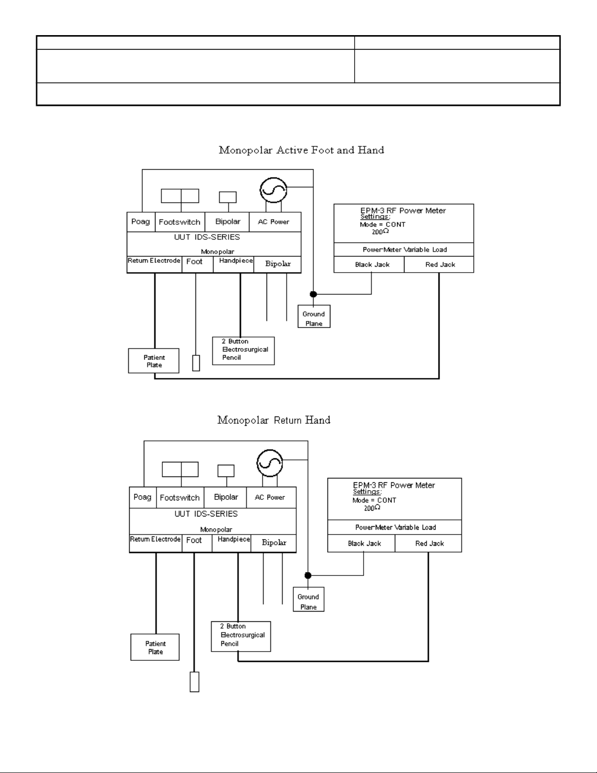
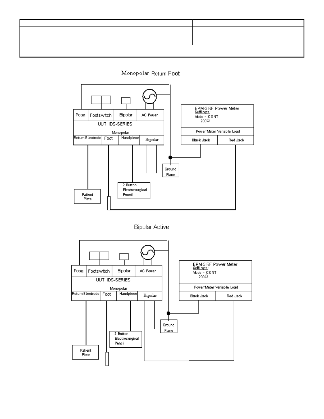
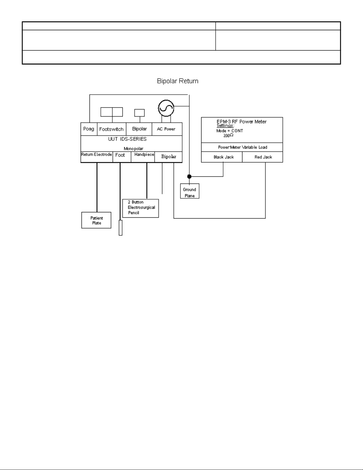
6.10.1 Long Leads HF leakage testing, Testing is conducted Per IEC 60601-2-2 3rd edition 1998-09 requirements section 19.1.101 (a) (2) for Monopolar and section 19.3.101 (a) (3) for bipolar testing. Refer to Appendix B for the test set up.
6.10.2 Test and record the HF leakage currents for all modes listed on the DHR at maximum power setting. Perform the leakage tests to the standards by activating with a handpiece and also with a footswitch.
6.10.3 Verify both Active and Return results are less than the established high limit and annotate pass or fail on the DHR.
Page 7

Bovie Medical Corporation Page: 7 of 28
Document Number: QA-256 Effective Date: 1/12/12
Revision No: 23
Title: TESTING PROCEDURE FOR THE IDS-SERIES ELECTROSURGICAL UNIT
6.11 Displays and LED’s
6.11.1 Turn unit on, and insert a shorted return electrode cable into the return electrode jack.
6.11.2 Verify that all modes can be selected and that all power adjustments (up and down) can be made via the front panel overlay.
6.11.3 Verify that all LED’s and display segments are functioning properly.
6.11.4 Verify that all NEM LED’s are functioning properly.
6.11.5 Connect a monopolar handpiece to the unit.
6.11.6 Verify that the Activation LED’s illuminate for each given mode type (Cut, Coag, and Bipolar).
6.11.7 Record Displays, LED’s Pass/Fail on the DHR.
6.12 Audio
6.12.1 Select Cut Mode and Spray mode.
Note: On Arthrex units, handpiece activation is disabled when a monopolar footswitch is
connected to the unit.
6.12.2 Depress the yellow button on the handpiece and verify that a low steady tone is sounded.
6.12.3 Depress the blue button on the handpiece and verify that a higher steady tone is sounded.
6.12.4 While activating the unit verify that the sound can be adjusted via the dial on the rear of the unit.
6.12.5 Verify that the alarm siren is sounded when the return electrode cable is removed from the unit.
6.12.6 Record Audio Pass/Fail on the DHR.
6.13 Accessory Inlet testing.
6.13.1 Connect test fixture F-195 to the accessory inlet located on the rear of the unit.
6.13.2 Activate the Cut I or Cut mode (model dependent) for 1 second and verify that the led on fixture F-195 illuminated and remains illuminated for 3 seconds after the unit is not activated.
6.13.3 Record Accessory Inlet Pass/Fail on the DHR
6.14 ARC and Cross Coupling Testing
Page 8

Bovie Medical Corporation Page: 8 of 28
Document Number: QA-256 Effective Date: 1/12/12
Revision No: 23
Title: TESTING PROCEDURE FOR THE IDS-SERIES ELECTROSURGICAL UNIT
6.14.1 Connect a return electrode cable to the return electrode jack on the unit.
6.14.2 Connect the other end of the grounding cable to the testing grounding plate.
6.14.3 Connect a two button handpiece to the monopolar jacks of the unit.
6.14.4 Select Cut I or Cut (model dependent) mode and set power to the maximum setting.
6.14.5 Activate the unit and tap the grounding plate with tip of pencil move the pencil off the
plate and take note of the ARC produced. Repeat this step for all monopolar modes at
the maximum power setting.
6.14.6 Verify that the unit does not exhibit any failures while the ARC is being produced, (RF
Shut Down, Blown Fuses, Scrambled Display, Blank Display, Incorrect Audio, Alarm
sounding, etc.)
6.14.7 Repeat steps 6.17.5 and 6.17.6 three times.
6.14.8 Repeat steps 6.17.5, 6.17.6 and 6.17.7 using a foot controlled pencil to verify that the
unit will ARC from the monopolar foot control jack when activation is requested via the
monopolar footswitch.
Note: The AR-9600 unit does not have a monopolar foot controlled output jack. When a
monopolar footswitch is connected to the rear of the unit, the buttons on the handpiece
are disabled. Output is delivered to the handpiece when activated via a monopolar
footswitch. This only applies to the AR-9600 units.
6.14.9 Connect a bipolar cable and forceps to the unit. Select maximum power for Bipolar
and ARC between the poles of the forceps. Activation is achieved via the bipolar
footswitch. Repeat 3 times.
6.14.10 Record ARC test Pass/Fail on the DHR.
6.14.11 CROSS COUPLE TESTING
6.14.12 Verify that RF output is only present through the appropriate jack (Monopolar foot
control jack or handpiece jack). During an activation request from a monopolar
handpiece, no RF output can be present from the monopolar foot control jack. During
an activation request from a footswitch, no RF output can be present from the
monopolar handpiece jack.
6.14.13 Testing is performed by connecting a 200-ohm load to the jack being tested and
monitoring the output power during activation of cut @MAX setting. The measured
value should be less than 150ma. Conduct the test so that the monopolar handpiece
is checked when the unit is activated via footswitch and that the foot controlled jack is
checked when the unit is activated via a monopolar handpiece. Record Cross
Coupling test Pass/Fail on the DHR.
Note: This test is not required for AR-9600 units. Mark N/A on DHR.
Page 9

Bovie Medical Corporation Page: 9 of 28
Document Number: QA-256 Effective Date: 1/12/12
Revision No: 23
Title: TESTING PROCEDURE FOR THE IDS-SERIES ELECTROSURGICAL UNIT
6.15 Activation Error Testing
6.15.1 F1-F5 is activation errors that indicate that the unit has been powered up with an
activation request. F3 and F4 are not applicable to the AR-9600.
6.15.2 Verify that F1-F5 can be simulated by turning on the power of the unit with a handpiece
or footswitch depressed during power up. Check all five errors. One for each way the
unit can be activated. The error code will be displayed in the bipolar display.
6.15.3 F6 indicated that the unit has sensed two activation requests. To simulate this error
while activating the cut mode activate a Coag mode, release the cut activation. F6 will
be displayed in the bipolar display.
6.15.4 Record Activation Errors F1-F6 Pass/Fail on the DHR
6.16 Load Curves
6.16.1 Turn unit on and connect a cable from the return electrode jack and connect from the
monopolar foot controlled output jack to the variable load connection on the side of the
Metron analyzer. Connect the monopolar footswitch cable to the green footswitch
jacks on the side on the Metron analyzer. Footswitch control will need to be toggled
between Cut, Coag, and Bipolar depending on the mode to be tested. Turn on the
Metron unit and select Remote Control Mode. Pressing F5 on the front of the unit and
then pressing F4 on the unit achieve this.
6.16.2 Turn on the computer workstation. Select the Pro Soft QA-ES icon to launch the
Metron software.
6.16.3 Once the program opens hit Ctrl+W to open the output power window.
6.16.4 From this window click on the File tab, then click on Load and select the
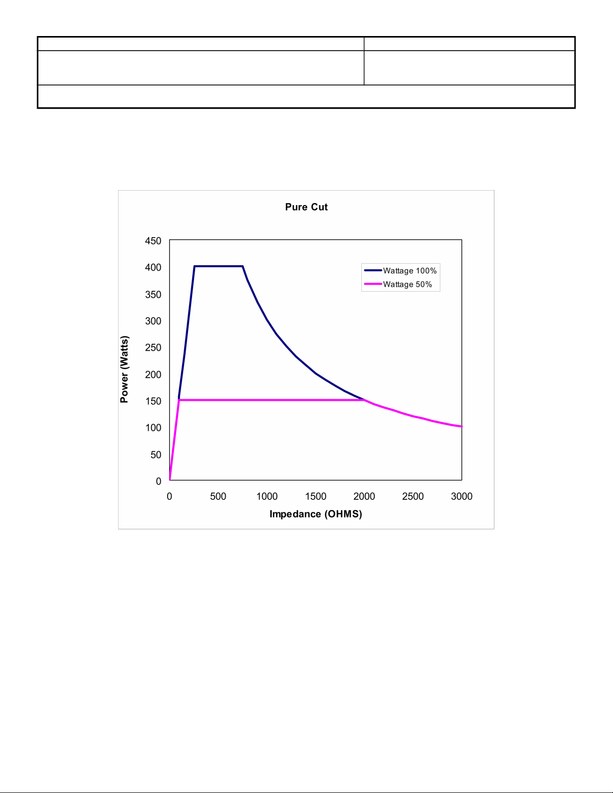
“IDS300_C.pwr” file for IDS300 and AR9600 units. For IDS200, A2250, & FHC22
units, select the “IDS200_D.pwr” file. For PB-400 units, select the “IDS400_A.pwr” file.
A list of the tests will be displayed. To start the tests hit F11 on the computer keyboard.
Follow the instructions on the computer to conduct each test.
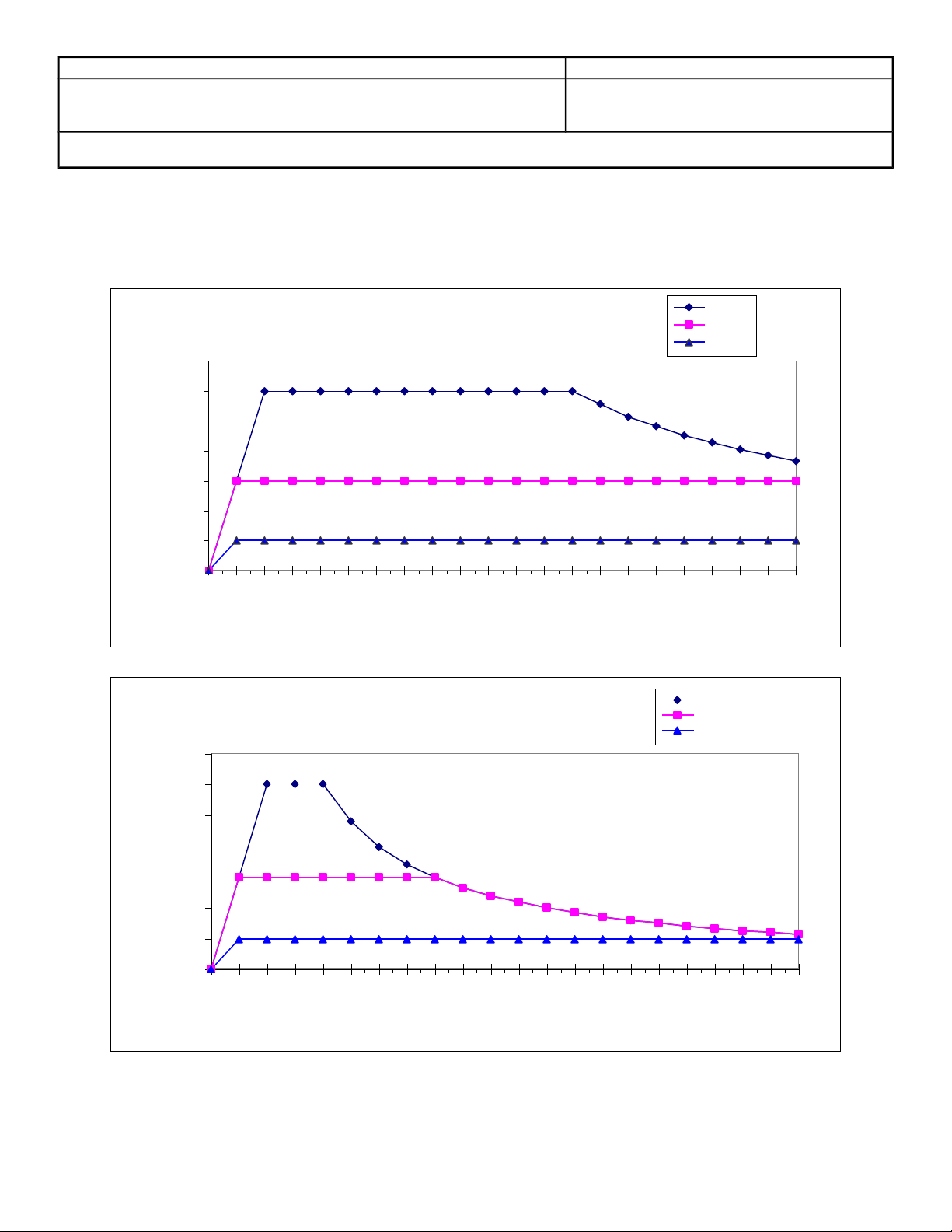
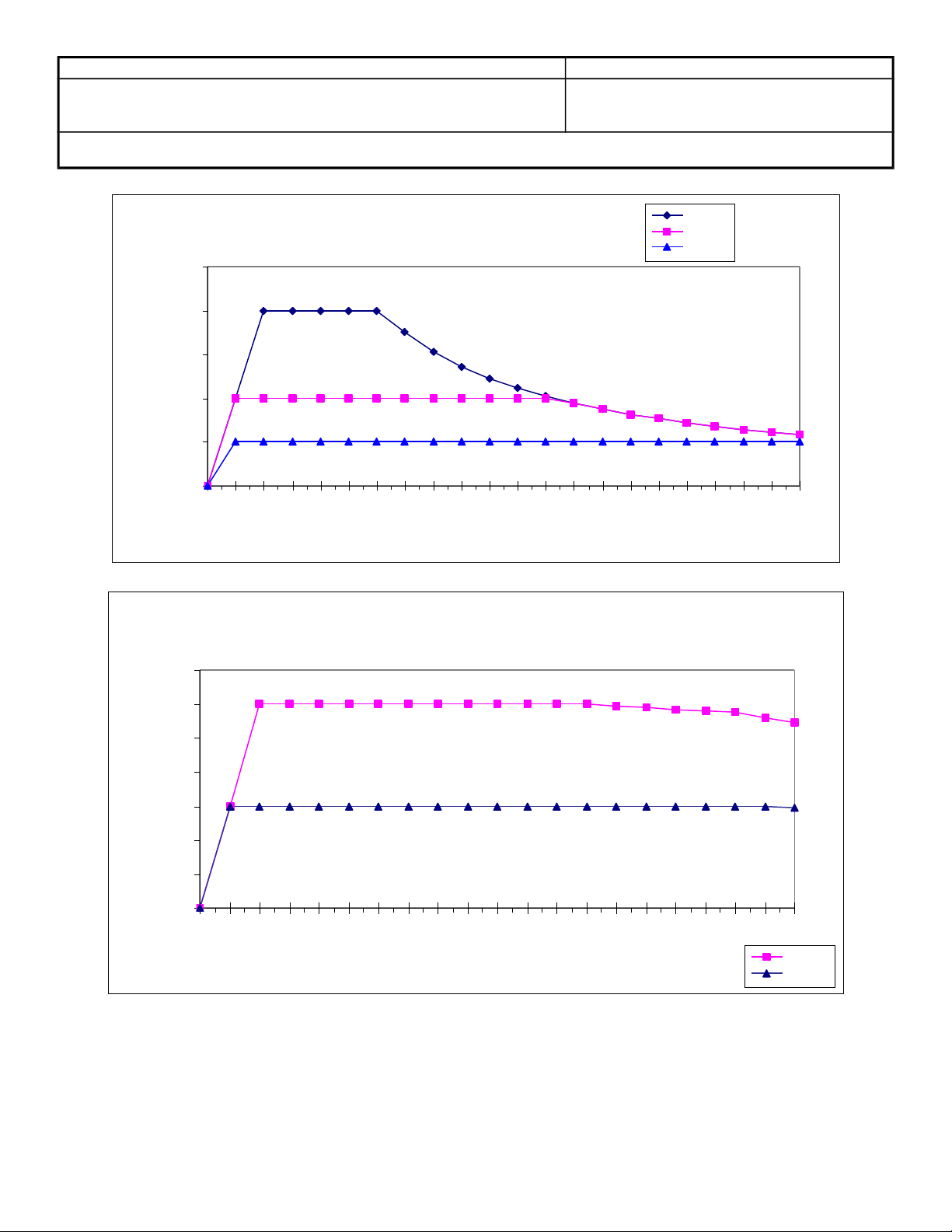
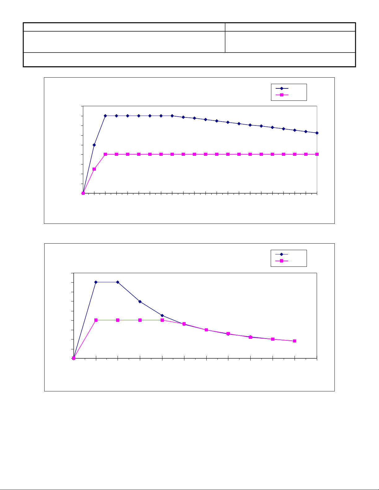
6.16.5 The Metron Electrosurgical Analyzer records load curves for each of the modes and
power settings listed on the DHR.
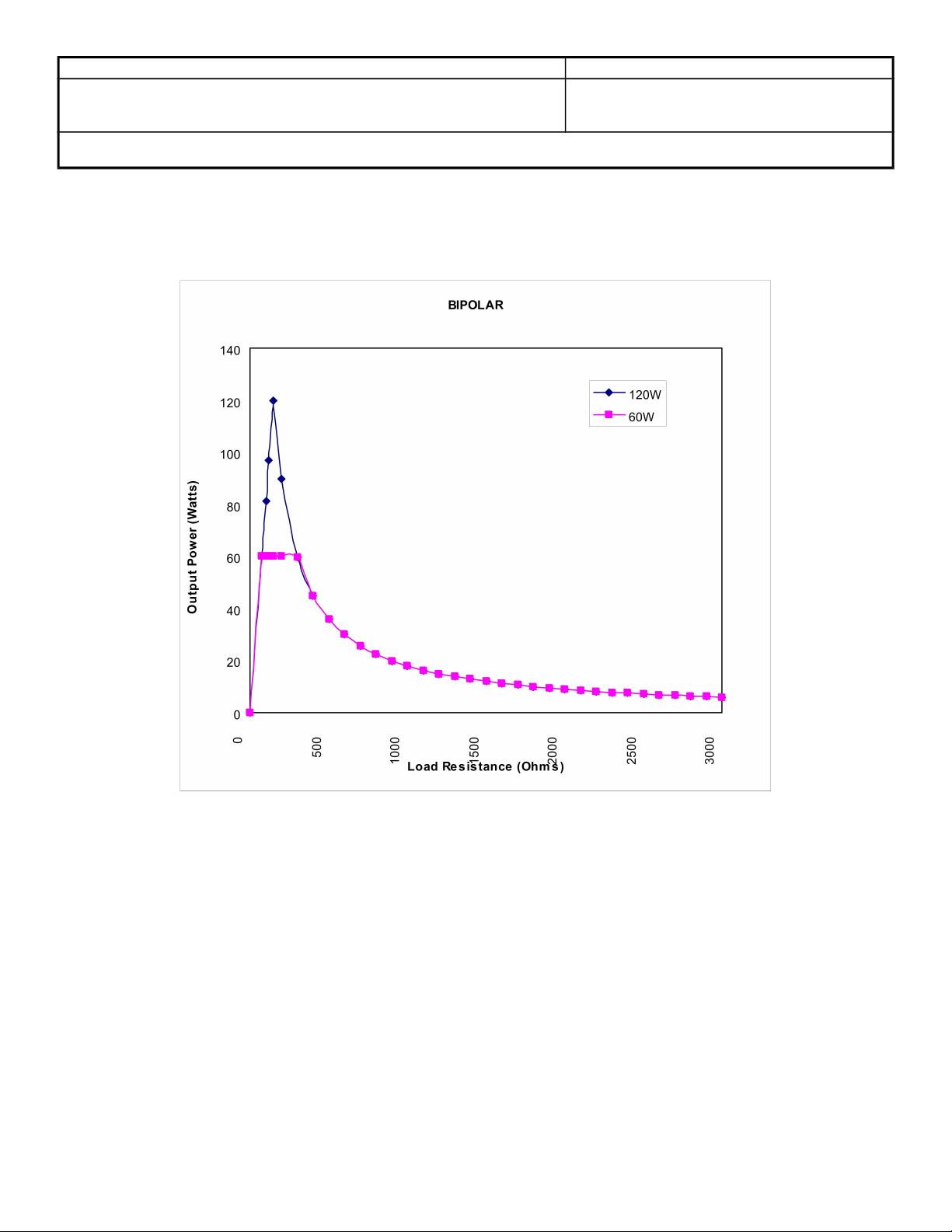
6.16.6 Print out a copy of the load curves and compare them to the load curves listed in
appendix A. To print out the curves as graphs check the graph setting under the
options – View power distrib. as window on the computer. To print the curve for a
mode, double click the mode and select print. The curves will not match perfectly. The
general shape and roll-off must be consistent. NOTE: On IDS200, A2250, & FHC22
units, the Cut load curve should be similar to the Cut 2 load curve in Appendix A.
**Record Serial Number of unit on each page of load curves.
6.16.7 Record results on DHR. Attach a copy of the load curves to the DHR.
Page 10
Bovie Medical Corporation Page: 10 of 28
Document Number: QA-256 Effective Date: 1/12/12
Revision No: 23
Title: TESTING PROCEDURE FOR THE IDS-SERIES ELECTROSURGICAL UNIT
6.17 Waveform Verification
NOTE: Waveform verification is to verify that the waveforms look similar to the ones listed
below. The waveforms are for reference only. All waveforms must be printed via the
oscilloscope for all modes tested and put with DHR.
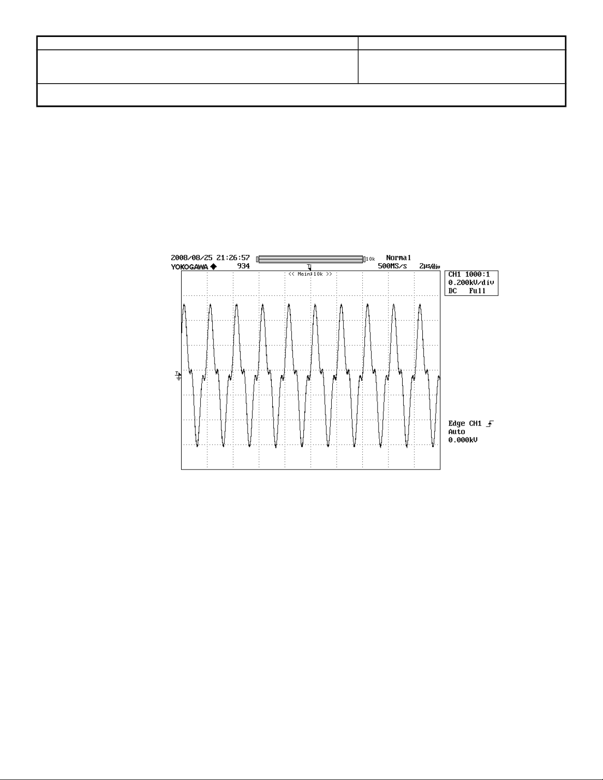
6.17.1 Turn the Oscilloscope on and set to 200V/div and 2usec/div. Using the 1000X probe,
connect the Oscilloscope to the Monopolar Foot Control and return electrode
connectors. Set the mode to Cut I and set the power to maximum output. Activate the
unit and verify the waveform looks approximately like the waveform in Figure 1.
Fig 1. Cut I Mode Open Circuit
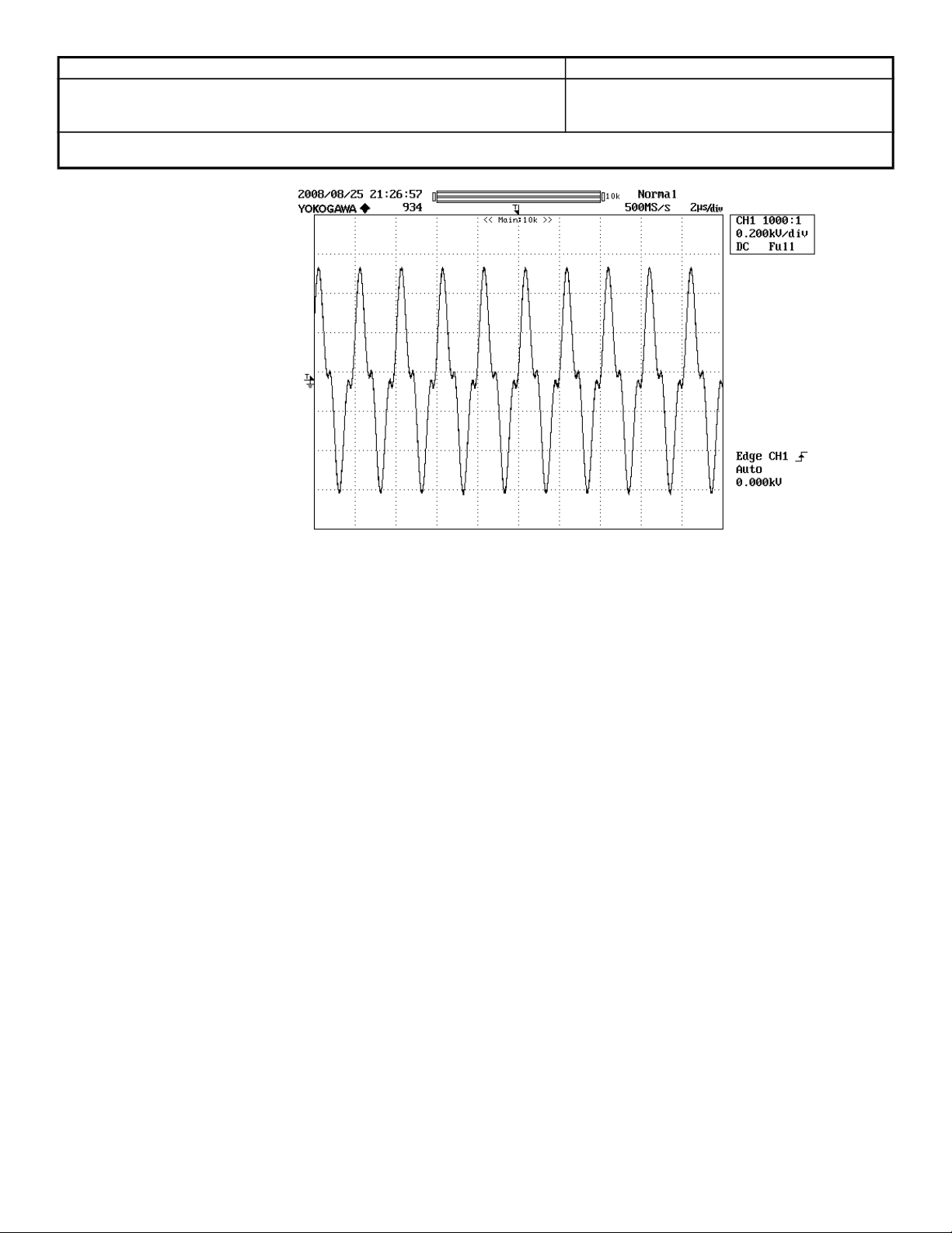
6.17.2 Turn the Oscilloscope on and set to 200V/div and 2usec/div. Using the 1000X probe,
connect the Oscilloscope to the Monopolar Foot Control and return electrode
connectors. Set the mode to Cut II and set the power to maximum output. Activate the
unit and verify the waveform looks approximately like the waveform in Figure 2.
Page 11
Bovie Medical Corporation Page: 11 of 28
Document Number: QA-256 Effective Date: 1/12/12
Revision No: 23
Title: TESTING PROCEDURE FOR THE IDS-SERIES ELECTROSURGICAL UNIT
Fig 2. Cut II Mode Open Circuit
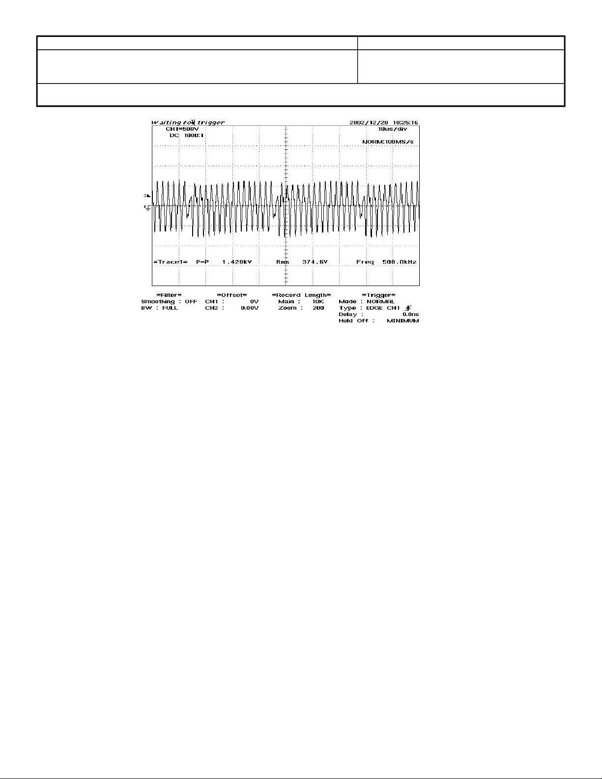
6.17.3 Turn the Oscilloscope on and set to 500V/div and 10usec/div. Using the 1000X probe,
connect the Oscilloscope to the Monopolar Foot Control and return electrode
connectors. Set the mode to Blend with 2 segments selected on the Blend bar and set
the power to maximum output. Activate the unit and verify the waveform looks
approximately like the waveform in Figure 3.
Page 12
Bovie Medical Corporation Page: 12 of 28
Document Number: QA-256 Effective Date: 1/12/12
Revision No: 23
Title: TESTING PROCEDURE FOR THE IDS-SERIES ELECTROSURGICAL UNIT
Fig 3. Blend Min Mode Open Circuit
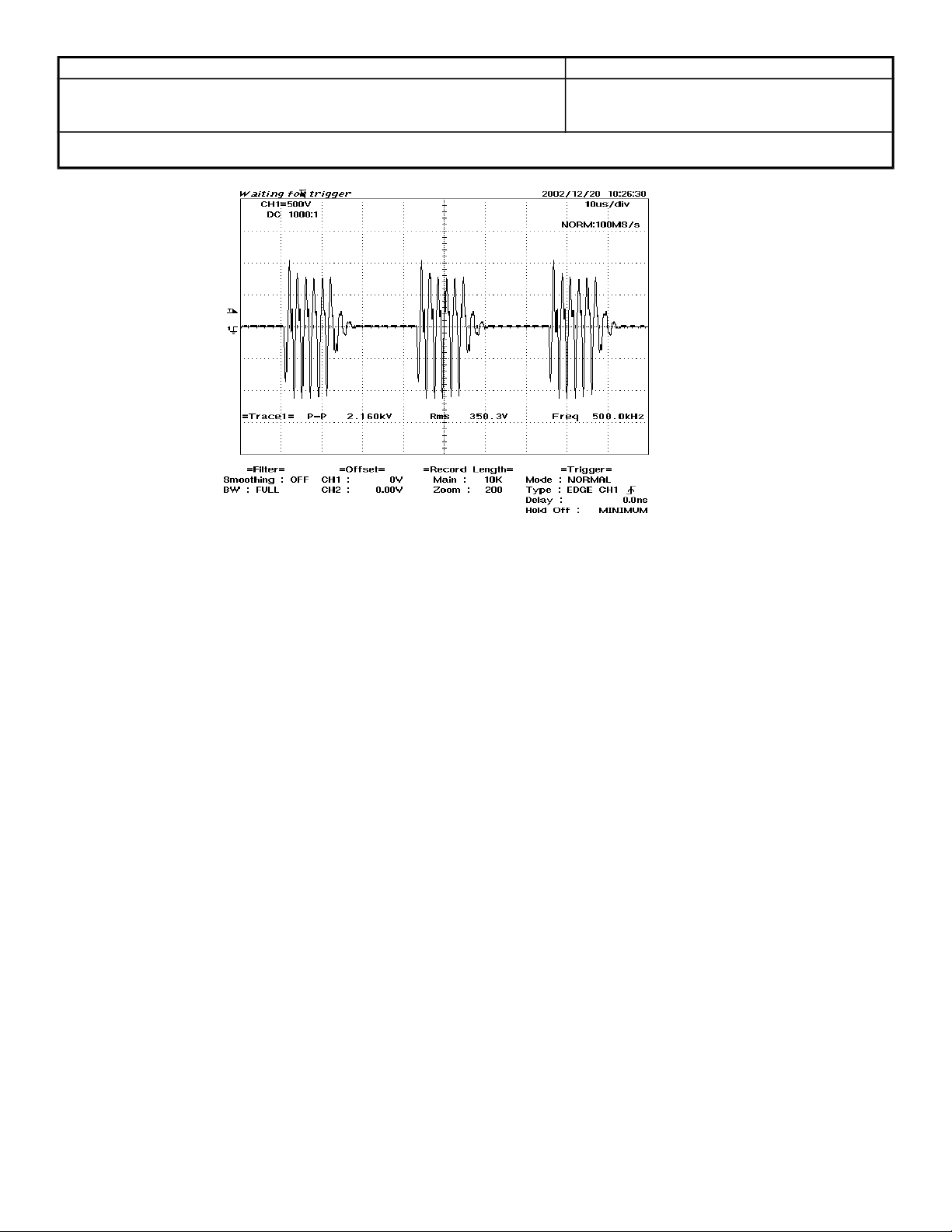
6.17.4 Turn the Oscilloscope on and set to 500V/div and 10usec/div. Using the 1000X probe,
connect the Oscilloscope to the Monopolar Foot Control and return electrode
connectors. Set the mode to Blend with all segments selected on the Blend bar and set
the power to maximum output. Activate the unit and verify the waveform looks
approximately like the waveform in Figure 4.
Page 13
Bovie Medical Corporation Page: 13 of 28
Document Number: QA-256 Effective Date: 1/12/12
Revision No: 23
Title: TESTING PROCEDURE FOR THE IDS-SERIES ELECTROSURGICAL UNIT
Fig 4. Blend Max Mode Open Circuit
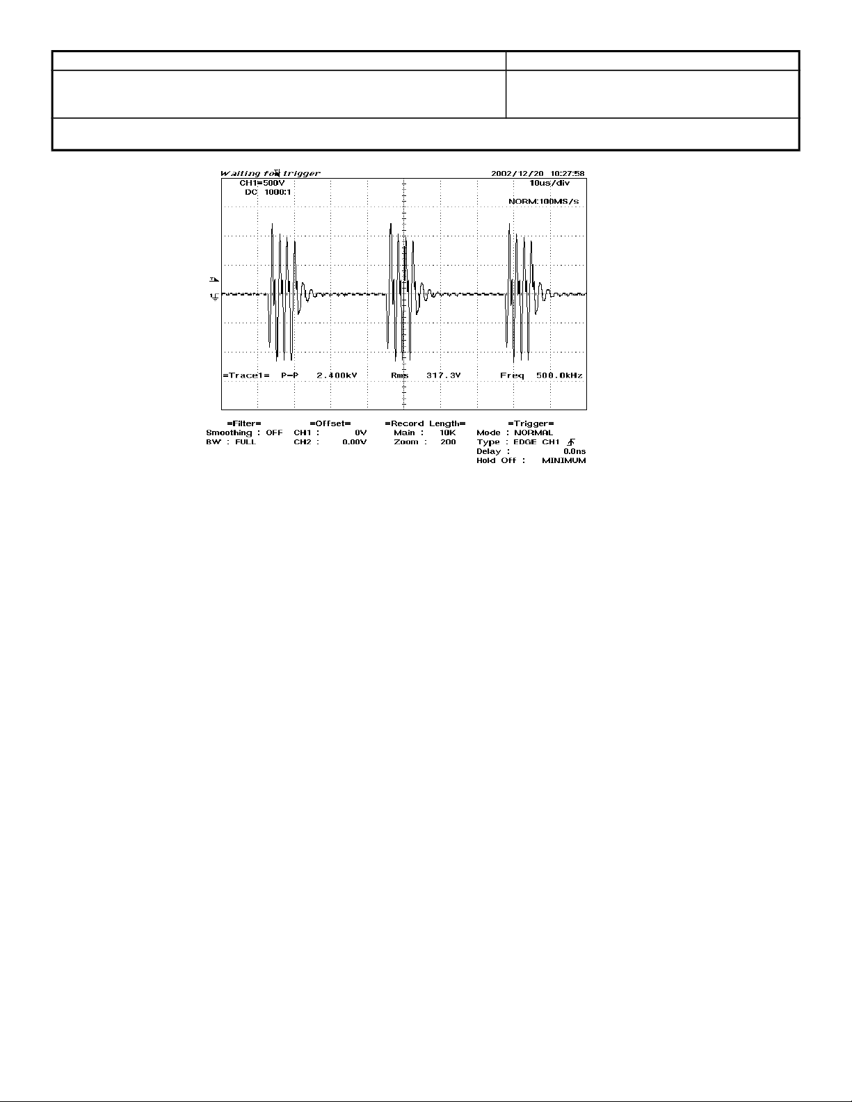
6.17.5 Turn the Oscilloscope on and set to 500V/div and 10usec/div. Using the 1000X probe,
connect the Oscilloscope to the Monopolar Foot Control and return electrode
connectors. Set the mode to Pinpoint and set the power to maximum output. Activate
the unit and verify the waveform looks approximately like the waveform in Figure 5.
Page 14
Bovie Medical Corporation Page: 14 of 28
Document Number: QA-256 Effective Date: 1/12/12
Revision No: 23
Title: TESTING PROCEDURE FOR THE IDS-SERIES ELECTROSURGICAL UNIT
Fig 5. Pinpoint Mode Open Circuit
Page 15
Bovie Medical Corporation Page: 15 of 28
Document Number: QA-256 Effective Date: 1/12/12
Revision No: 23
Title: TESTING PROCEDURE FOR THE IDS-SERIES ELECTROSURGICAL UNIT
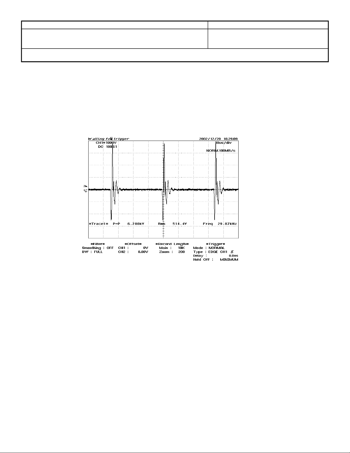
6.17.6 Turn the Oscilloscope on and set to 1000V/div and 10usec/div. Using the 1000X probe,
connect the Oscilloscope to the Monopolar Foot Control and return electrode
connectors. Set the mode to Spray and set the power to maximum output. Activate the
unit and verify the waveform looks approximately like the waveform in Figure 6.
Fig 6. Spray Mode Open Circuit
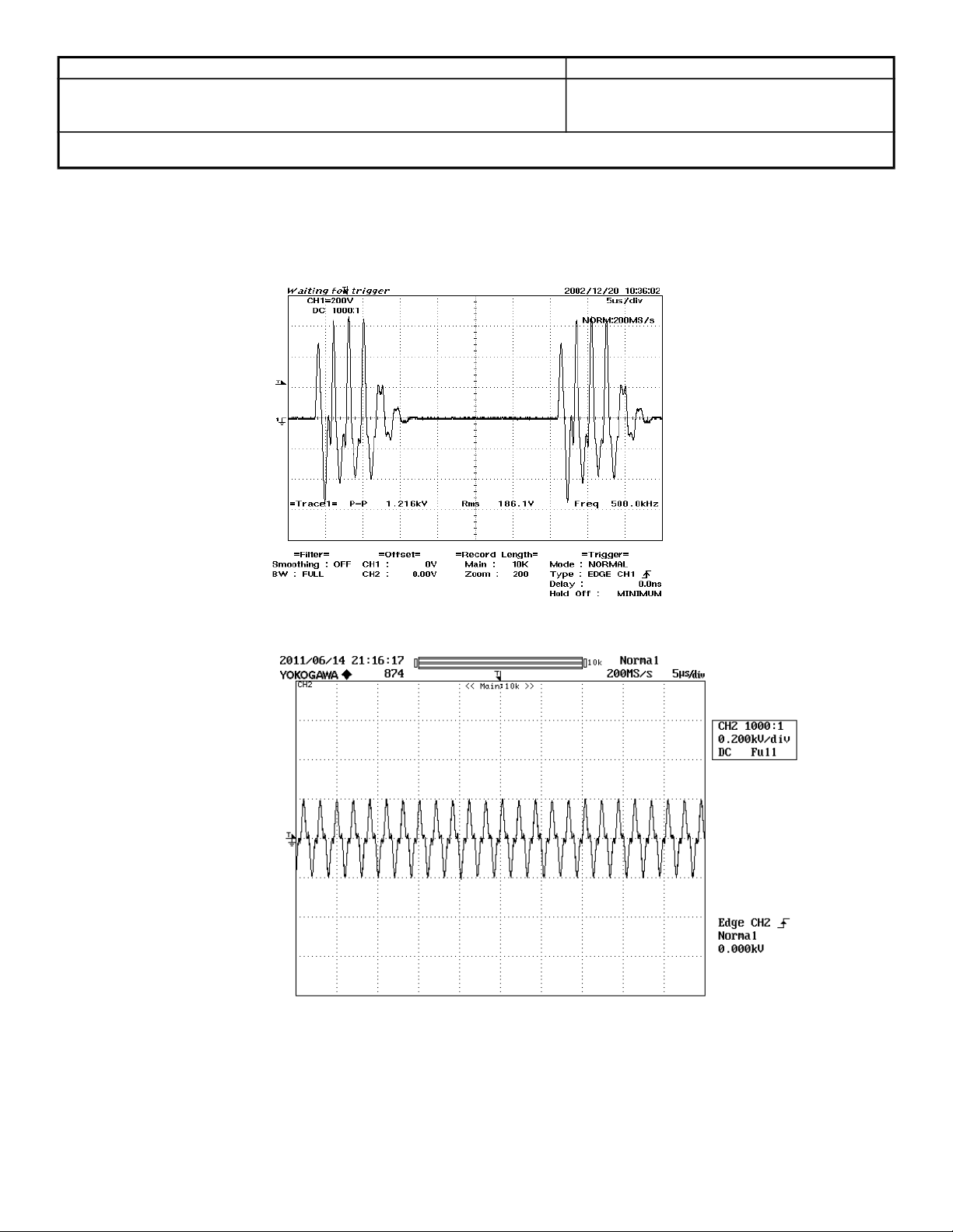
6.17.7 Turn the Oscilloscope on and set to 200V/div and 5usec/div. Using the 1000X probe,
Page 16
Bovie Medical Corporation Page: 16 of 28
Document Number: QA-256 Effective Date: 1/12/12
Revision No: 23
Title: TESTING PROCEDURE FOR THE IDS-SERIES ELECTROSURGICAL UNIT
connect the Oscilloscope to the Bipolar active and return jacks. Set the power to
maximum output for bipolar. Activate the unit and verify the waveform looks
approximately like the waveform in Figure 7 (for Arthrex only) or Figure 7a (for IDS
200W/300W series, and 400W series units).
Fig 7. Bipolar Mode Open Circuit ( Arthrex models only)
Fig 7a. Bipolar Mode Open Circuit (200W, 300W, and 400W models)
6.17.8 Record the results on the DHR and put printouts with DHR.
6.18 Output Power
6.18.1 Refer to section 6.7 for setups.
Page 17

Bovie Medical Corporation Page: 17 of 28
Document Number: QA-256 Effective Date: 1/12/12
Revision No: 23
Title: TESTING PROCEDURE FOR THE IDS-SERIES ELECTROSURGICAL UNIT
6.18.2 Record Output in Watts displayed on the Metron for each mode on the DHR.
6.19 Presets (IDS-300 and Arthrex Only)
6.19.1 Select preset “0” by pressing the recall button. Select a Cut mode and set the output
power to 2 watts.
6.19.2 Press and hold the Set button for 3 seconds and verify that the “0” flashes and that Cut
mode at 2 watts has been stored in preset location 0.
6.19.3 Reset the unit and verify that preset “0” is set to Cut at 2 watts.
6.19.4 Decrease the power to 0 watts in cut mode and verify that a small dot is blinking in the
lower right hand corner of the preset display. Press and hold the Set Button and verify
the “0” flashes and that Cut made at 0 watts has been stored.
6.19.5 Record Preset Pass/Fail on the DHR.
6.19.6 Refer to Doc-476 and set each of the memory locations as listed by model.
6.19.7 Record Factory Presets set on DHR.
6.20 Pre-Close Verification
6.20.1 Make sure that all test jumpers have been removed.
6.20.2 Inspect that all cables are connected securely
6.20.3 Verify that no foreign material is inside ESU.
6.20.4 Attach cover per DWG-18-077
6.20.5 Invert unit and shake.
6.21 Final Verification
6.21.1 Turn power switch to "on" position, wait a moment, then visually and audibly check that
unit does not begin automatic activation.
6.21.2 Manually select presets 0 thru 9, visually confirm actual numeric characters per DOC-
476.
6.21.3 Turn power switch to "off" position.
6.21.4 Verify Final Assembly Router and DHR are completed. No blank spots, missing data or
overwrites.
6.21.5 Sign and date the Final Verification/Certification line.
6.22 Refer to WI-0387 for Packaging.
Page 18

Bovie Medical Corporation Page: 18 of 28
Document Number: QA-256 Effective Date: 1/12/12
Revision No: 23
Title: TESTING PROCEDURE FOR THE IDS-SERIES ELECTROSURGICAL UNIT
7.0 IN-PROCESS FAILURES
7.1 Identify Failure
7.1.1 Units that fail during the testing are treated as non-conforming material and are handled per QA-080.
7.1.2 Information is recorded on the Final Assembly Router to record information regarding the
failure to aid in troubleshooting of the problem. In the event that the problem is not
repeated or considered technician error, this information is recorded on the Final
Assembly Router and the testing continues at the point the problem occurred.
7.1.3 Refer to WI-0388 for Failure Codes.
7.1.4 Record When and Symptom Codes on the Failure Record Section of the Final Assembly Router and explain in Comments Section.
7.1.5 Repair person, if necessary, utilize Technical Manual and test equipment to troubleshoot unit. Identify cause of failure.
7.1.6 Record failure information Assembly Number, Failure Code, Component Designator, and Part Number also in Comments Section as required on the Final Assembly Router. Repair Unit as required/needed.
7.2 Re-Test
7.2.1 Verify that the repair did correct the problem by conducting the same test that the unit failed for originally.
7.2.2 The complete testing procedure must be conducted under the following conditions
7.2.2.1 Any electrical component was found non-conforming and had to be replaced
7.2.2.2 Replacement of PCB assembly
7.2.2.3 Per instructions on ECN or temporary process
7.2.3 If the repair was due to a mechanical failure, ex: switch defective, bad connection, or cosmetic defect the unit testing will precede at the point the failure was observed.
7.3 Repair/ Retest Documentation
7.3.1 Verify that all failure information on the Final Assembly Router is complete and legible.
7.3.2 Initial the Re-Test box of the Failure Record after the Unit has been repaired and is functioning properly.
7.3.3 All code, information, and initials must be entered for each failed component.
7.3.4 If additional space needed, record the information on back of Final Assembly Router.
Page 19
Bovie Medical Corporation Page: 19 of 28
Cut I
0
50
100
150
200
250
300
350
0 500 1000 1500 2000
Load Re sistance [Ohms]
Output Power [Watts]
300W
150W
50W
Cut 2
0
50
100
150
200
250
300
350
0 500 1000 1500 2000
Load Resistance [Ohms]
Output Power [Watts]
300W
150W
50W
Document Number: QA-256 Effective Date: 1/12/12
Revision No: 23
Title: TESTING PROCEDURE FOR THE IDS-SERIES ELECTROSURGICAL UNIT
APPENDIX A
IDS 300 Load Curves
Page 20
Bovie Medical Corporation Page: 20 of 28
Blend Max
0
50
100
150
200
250
0 500 1000 1500 2000
Load Re sistance [Ohms]
Output Power [Watts]
200W
100W
50W
Pinpoint Coag
0
20
40
60
80
100
120
140
0 500 1000 1500 2000
Load Resistance [Ohms]
Output Power [Watts]
120W
60W
Document Number: QA-256 Effective Date: 1/12/12
Revision No: 23
Title: TESTING PROCEDURE FOR THE IDS-SERIES ELECTROSURGICAL UNIT
Page 21
Bovie Medical Corporation Page: 21 of 28
Spray Coag
0
10
20
30
40
50
60
70
80
90
0 500 1000 1500 2000
Load Re sistance [Ohms]
Output Power [Watts]
80W
40W
Bipolar
0
10
20
30
40
50
60
70
80
90
0 500 1000
Load Resistance [Ohms]
Output Power [Watts]
80W
40W
Document Number: QA-256 Effective Date: 1/12/12
Revision No: 23
Title: TESTING PROCEDURE FOR THE IDS-SERIES ELECTROSURGICAL UNIT
Page 22
Bovie Medical Corporation Page: 22 of 28
Document Number: QA-256 Effective Date: 1/12/12
Revision No: 23
Title: TESTING PROCEDURE FOR THE IDS-SERIES ELECTROSURGICAL UNIT
IDS-400 Load Curves
Cut I Mode (all other modes except Bipolar match the prior ones)
Page 23
Bovie Medical Corporation Page: 23 of 28
Document Number: QA-256 Effective Date: 1/12/12
Revision No: 23
Title: TESTING PROCEDURE FOR THE IDS-SERIES ELECTROSURGICAL UNIT
IDS-400 Load Curves
Bipolar Mode
Page 24
Bovie Medical Corporation Page: 24 of 28
Document Number: QA-256 Effective Date: 1/12/12
Revision No: 23
Title: TESTING PROCEDURE FOR THE IDS-SERIES ELECTROSURGICAL UNIT
Appendix B
Note: For AR-9600 this setup is used for Hand and Foot Return
Page 25
Bovie Medical Corporation Page: 25 of 28
Document Number: QA-256 Effective Date: 1/12/12
Revision No: 23
Title: TESTING PROCEDURE FOR THE IDS-SERIES ELECTROSURGICAL UNIT
Page 26
Bovie Medical Corporation Page: 26 of 28
Document Number: QA-256 Effective Date: 1/12/12
Revision No: 23
Title: TESTING PROCEDURE FOR THE IDS-SERIES ELECTROSURGICAL UNIT
Page 27
Bovie Medical Corporation Page: 27 of 28
Document Number: QA-256 Effective Date: 1/12/12
Revision No: 23
Title: TESTING PROCEDURE FOR THE IDS-SERIES ELECTROSURGICAL UNIT
DOCUMENT CHANGE HISTORY
REV. DESCRIPTION OF CHANGE
0 New Document 1/06/2003 03010601
Add instructions for setting Presets. Update load curves, Update burn-in
1
procedure
Add 6.3.2 & 6.3.3 test procedures and perform some administrative corrections 10/6/2003 03080604
2
Sec. 6.5B Modified toward manual method of testing
3
Step 6.6.8 Added, Step 6.8.2 Removed references to computer file
Step 6.11.2 Add detail about testing with both a handpiece and footswitch.
Step 6.20.7 Added detail for IDS200 Cut curve
Appendix A – Pinpoint curve changed to current version
4 Change the Coag line current limit from 1.7 to 1.85 on sec. 6.3.2 12/19/2003 03121201
5 ADD 4.11 QA-196, 4.12 WI-0387, & 4.13 WI-0388
Sec. 6.1.2 REWORD and CORRECT “U3” to “U4”
Sec. 6.2A and 6.2B ADD letter designator to all
MOVE Service Mode Data from 6.19 to 6.2 and RENUMBER
Move 6.3.3 to 6.2 (will become 6.2.5)
Sec. 6.5A DELETE, Sec. 6.5B REMOVE letter designator & “Using Metron”
Sec. 6.7.2 ADD Install cover
Sec. 6.8 DELETE, Sec. 6.8B REMOVE letter designator & “Using Metron
Sec. 6.10.13 CORRECT 150 to 155
Sec.6.11 ADD “(Using FM Power Meter)”
Sec. 6.18 ADD “(IDS-300 & Arthrex Only)”
Sec. 6.18.5 ADD “, Sec. IIX, Sec. 6.18.7 REWORD and ADD “, Sec.IIX”
Sec. 6.19.3 ADD “, Sec. IIX”, Sec.6.19.4 ADD “record on DHR, Sec. IIX
Sec. 6.21 REMOVE “and Packaging” ADD “/Certification”
Sec. 6.21.1 REMOVE “inside the unit”, REMOVE “Verify that nothing is loose”
ADD about jumpers, verify presets, and verify arcing
Sec. 6.21.2 REWORD, Sec.6.21.3 CHANGE to “Attach cover per DWG-18-077”
Sec. 6.21.4 – 6.21.7 DELETE, ADD Sec. 6.22 Refer to WI-0387 for Packaging
Sec. 7.1.3 CHANGE to Refer to WI-0388 for Failure Codes
Sec.7.1.7 ADD “/needed”, Appendix B DELETE
6 Addition of Short Leads RF Leakage Testing as Sec. 6.13 Re-order subsequent
test steps to support Short Leads Test insertion. Power settings to zero &
activate for all units not having preset requirements. Notes requiring installed
cover for all RF leakage tests. Sec. 6.20.4 & Sec. 6.20.5, add units A2250 &
FHC22.
7 5.16-change reference to fixture F-248 to fixture F-309. Sec. 6.11 change fixture
F-248 to F-309.
8 Add Steps 6.2.3 to 6.2.8 regarding additional voltage measurements. Change
old 6.2.3 to 6.2.9 and 6.2.4 to 6.2.10. Corrected numbering scheme.
EFFECTIVE
DATE
2/21/2003 03021801
10/28/2003 03100903
4/28/2004 04032304
5/24/2004 04051203
6/28/2004 04062404
07/14/2004 04071301
ECN#
DOCUMENT CHANGE HISTORY
Page 28
Bovie Medical Corporation Page: 28 of 28
Document Number: QA-256 Effective Date: 1/12/12
Revision No: 23
Title: TESTING PROCEDURE FOR THE IDS-SERIES ELECTROSURGICAL UNIT
REV. DESCRIPTION OF CHANGE
9 Changed note in 6.4.1 to separate paragraph
Numbered sentence under “WARNING” in 6.5A & 6.5B, renumbered remaining
Corrected numbering sequence in 6.7
Added 6.7.3 in whole and added “ For units with 20-056-xxx display brd,” to
6.7.2
Changed in 6.8.1 “1600V” to “1.84kV”
Changed 6.12.5 and 6.13.4 to note & moved before .1 respectively.
Added Section IX after DHR in 6.14.6, 6.15.8, 6.16.5, 6.17.36.18.11, 6.18.13 &
6.19.4
Corrected sentence reference in 6.18.7 & 6.18.9
Corrected ‘Sec. IIX’ to Section IX in 6.20.5 & 6.20.7
Numbered bullets under 6.22.2.5
Changed note under 6.22.2.5 and added sentence numbers to three process
steps & renumbered remaining sentences
Removed 6.22.6 “Apply tamper seal”
Numbered bullets in 7.2.2
Realigned DHR section number references to new layout of DHR (NEM moved
to first section)
10 Removed section 6.13 High Frequency Testing, short leads.
Added into section 6.8.4 different B/I configurations by model
Reordered some paragraphs and references to DHR record sections
11 Section 6.8.4, removed 6.8.4.2 & 6.8.4.3 and changed 6.8.4.1 so that all units
are burned in the same. Load application is the same.
12 Sec. 6.1 and 6.8 – add note about testing/burning in PB-400 units at 240VAC.
Sec. 6.5.1 – add note about line current for PB-400 to be taken at 240VAC.
Sec. 6.10.4 – add reference to IDS400 load curve file.
Appendix A – add PB-400 load curve for Cut I mode.
13 Remove references to 240VAC requirements to test PB-400 units – Sections
6.1, 6.8
Correct load resistance for Cut I on 400W models – Sec. 6.7
Correct line current for Cut I for 400W models – Sec. 6.5
Add bipolar IDS-400 load curve to Appendix A
14 Added Load specification for Coag Line Current test. Sec. 6.5.2 11/6/07 07103104
15 Correct the ideal Waveform picture to the actual CUT I and II waveform –
Section 6.12.1 and 6.12.2.
16 Sec. 6.12.7 – Added Figure 7a for the bipolar mode open circuit waveform of
400W models (updated after performing VP-0814)
17 Sec. 6.4B and 6.6B - Replace Kelvin Probe to Alligator clips.
Sec. 6.5.1 – Added 500 load for 400 watts Series Line Current Cut test.
18 Sec. 6.12.7 Updated figure 7 and 7a descriptions for new Bipolar waveform. 05/11/10 10050301
19 Sec. 6.3 Added Maximum LED lit setting before setting the DC Power Supply. 3/9/2011 11022803
20 Updated entire Procedure 7/20/2011 11071306
21 Corrected screw check 6.1.3.3 to 8 screws 8/8/2011 11080104
22 Added Section 6.1.3.4 and Section 6.1.3.5 to ensure that components are not
touching.
23 Add note to record serial number on each page of load curves. 1/12/2012 12010101
EFFECTIVE
DATE
08/30/2004 04081804
6/24/05 05062202
11/8/05 05110308
11/22/06 06111702
3/20/07 07031207
9/5/08 08082504
1/7/2010 09121401
4/16/10 10041204
12/20/2011 11121202
ECN#
 Loading...