

Page 1
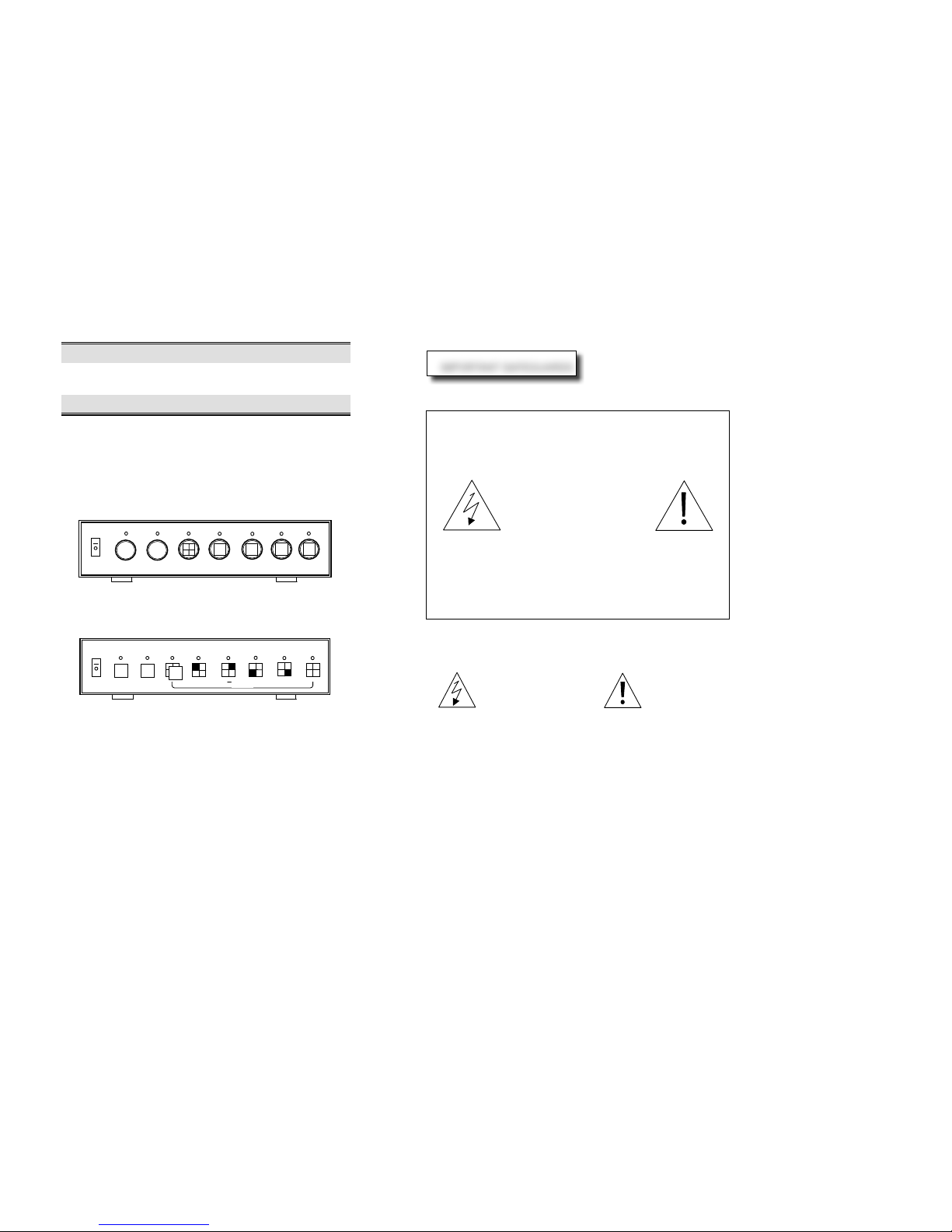
B/W & COLOR VIDEO QUAD PROCESSOR
OPERATION MANUAL
BQ4 / CQ4
BQ4AZ / BQ4BZ / CQ4Z
** Before operating the unit , please read this manual carefully .
WARNING
TO PREVENT FIRE OR ELE CTRIC SHOCK , DO NOT EXPOSE THIS
APPLIANCE TO RAIN OR MOISTUR E
CAUTION
RISK OF ELECTRICAL SHO CK
DO NOT OPEN !
CAUTION ! TO PREV ENT ELECTRIC S HOCK DO NOT REMOVE
COVER. NO USER SE RVICEABLE COM PONENTS INSIDE. BEFORE
SERVICING TO QUALIFIED SERVICE PERSONNEL
The lightning flash
The exclamation
with the arrowhead
within an point
Symbol, with-in an
equilateral to alert
Equilateral triangle,
the user to the
is intended to alert th e user to
presence of importan t
the presence of unins ulated
operating and mainte nance
" dangerous voltage " within
( servicing ) in the lite rature
the product's enclosu re that
the appliance .
magnitude to may be of
sufficient constitute a ris k of
electric shock to pers ons .
←
IMPORTANT SAFEGUARDS
3
VCR
ZOOM
1 2 4
SW
AUTO
HOLD
4/4
LOCK
AUTO
DWELL
SET
ALARM
SET
10 SEC. 1 1 SEC.
3 4 2
Page 2
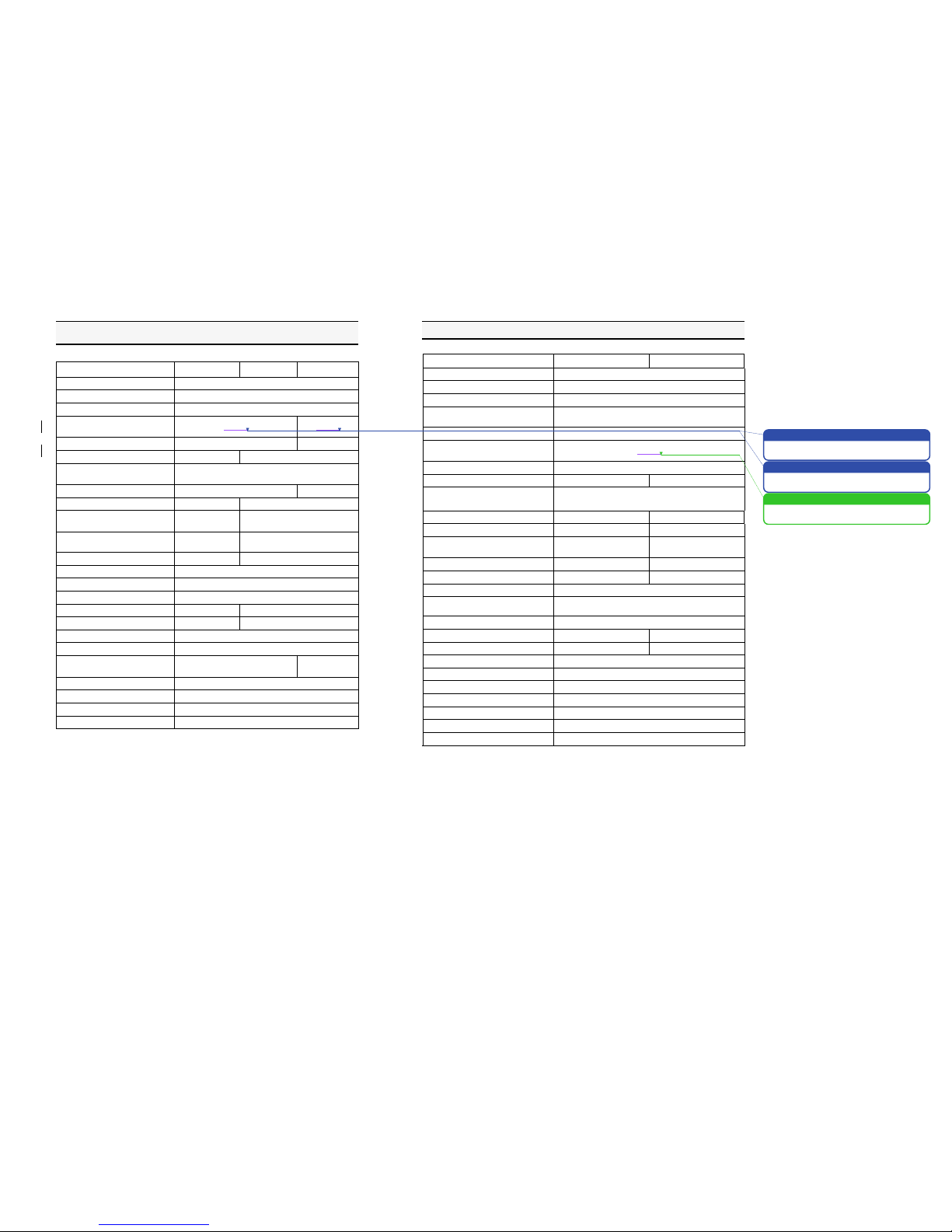
** B/W QUAD SERIES **
SPECIFICATION :
MODEL NO.
BQ4
BQ4AZ
BQ4BZ
CAMERA TYPE
BLACK & WHITE ( EIA OR CCIR )
CAMERA INPUT
4
GAIN CONTROL
MANUAL ADJUSTMENT
PICTURE REFRESH RATE
FIELDS/SEC.
30 (25)
60 (50)
DIGITAL MEMORY
1024 x 512
2048 x 512
VCR ZOOM
NO
YES
VIDEO OUTPUT
MONITOR OUT x 1 , 1Vp-p , 75 ohms
VCR OUT x 1 , 1Vp-p , 75 ohms
LOOPING OUT
NO
YES
MENU SETUP
NO
YES
TITLES
NO
8 CHARACTER TITLES FOR
EACH CAMERA
TIME & DATE
( LOCATION SETTING )
NO
YES
VIDEO LOSS DETECTION
NO
YES
ALARM INPUT
NC. OR NO. SENSOR INPUT x 4
ALARM OUTPUT
NC. & NO. RELAY CONTACT OUTPUT , 24 VDC /1A
ALARM DURATION
1 TO 99 SEC.
DWELL TIME
1 TO 99 SEC.
0 TO 99 SEC.
BUZZER
NO
YES
SECURITY LOCKOUT
YES
RACK MOUNTABLE
YES
POWER SOURCE
12V TO 24V /
AC OR DC , 0.5A
12V TO 24V /
AC OR DC , 1A
POWER CONSUMPTION
LESS THAN 5 Watts
OPERATION TEMPERATURE
0° C TO 50° C
DIMENSION
285mm ( W ) x 235mm ( D ) x4 4mm ( H )
WEIGHT ( with power adaptor )
2.5kg
*** Specification subject to change without no tice ***
- 1 -
** COLOR QUAD SERIES **
SPECIFICATION :
MODEL NO.
CQ4
CQ4Z
CAMERA TYPE
COLOR ( NTSC OR PAL )
CAMERA INPUT
4
DUAL SYSTEM ( NTSC & PAL )
YES
DSP
( DIGITAL DECODER & ENCODER )
YES
AGC ( AUTO GAIN CONTROL )
YES
PICTURE REFRESH RATE
FIELDS/SEC.
60 (50)
DIGITAL MEMORY
1024 x 512
VCR ZOOM
NO
YES
VIDEO OUTPUT
MONITOR OUT x 1 , 1Vp-p , 75 ohms
VCR OUT x 1 , 1Vp-p , 75 ohms
LOOPING OUT
NO
YES
MENU SETUP
NO
YES
TITLES
NO
8 CHARACTER TITLES
FOR EACH CAMERA
TIME & DATE ( LOCATION SETTING )
NO
YES
VIDEO LOSS DETECTION
NO
YES
ALARM INPUT
NC. OR NO. SENSOR INPUT x 4
ALARM OUTPUT
NC. & NO. RELAY CONTACT OUTPUT ,
24 VDC /1A
ALARM DURATION
1 TO 99 SEC.
DWELL TIME
1 TO 99 SEC.
0 TO 99 SEC.
BUZZER
NO
YES
SECURITY LOCKOUT
YES
RACK MOUNTABLE
YES
POWER SOURCE
12V TO 24V / AC OR DC , 1A
POWER CONSUMPTION
7 Watts
OPERATION TEMPERATURE
0° C TO 50° C
DIMENSION
285mm ( W ) x 235mm ( D ) x4 4mm ( H )
WEIGHT ( with power adaptor )
2.5kg
*** Specification subject to change without no tice ***
- 2 -
jenny! 28/6/01 09:56
jenny! 28/6/01 09:57
annie! 2/2/04 16:34
Deleted: 15
Deleted: 30
Deleted: 30
Page 3
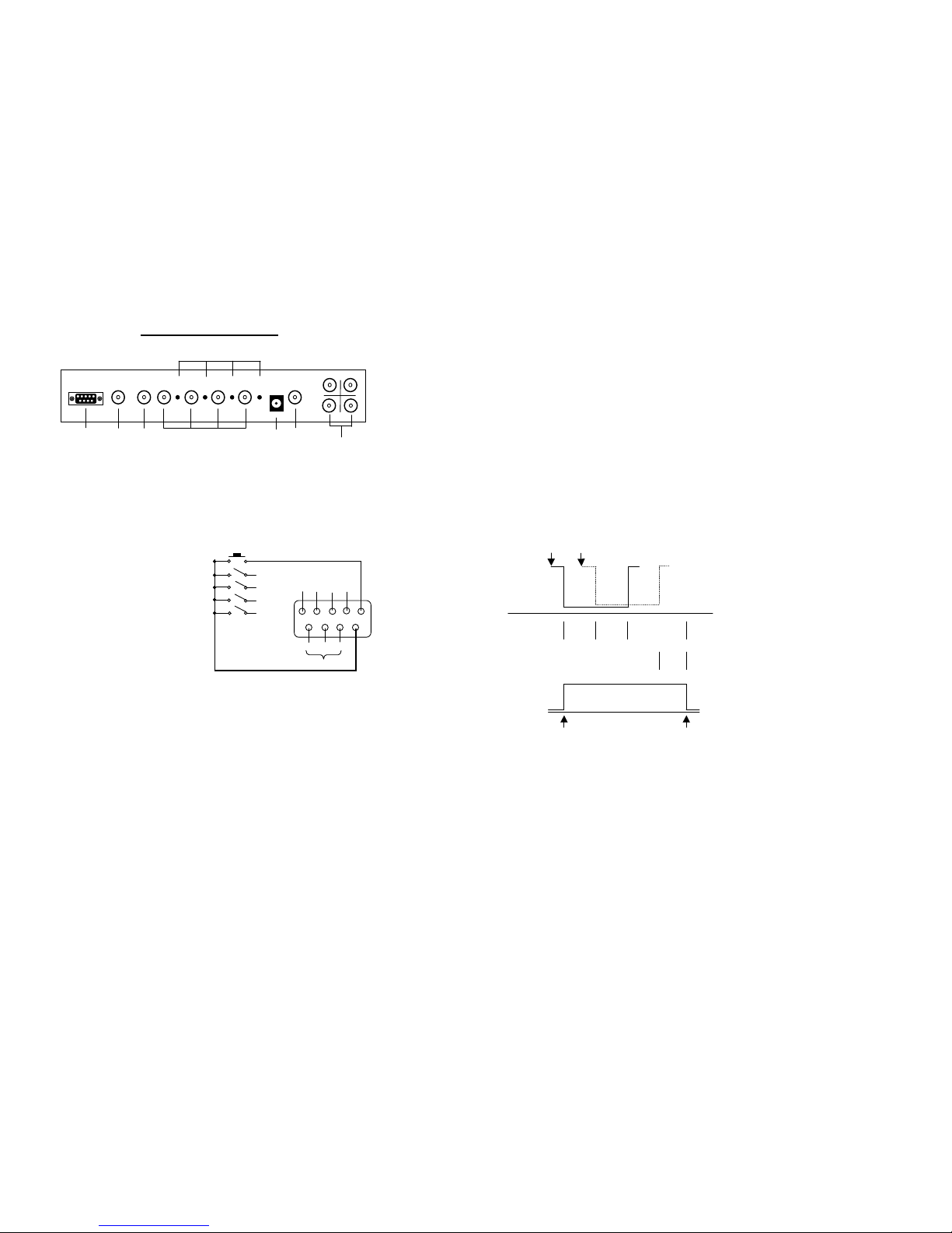
REAR PANEL DESCRIPTION
1.
ALARM : It's 9 Pins D-SUB connector for alarm input-output , as This signal commands the unit to :
a.
Go into full screen mode for sing le alarm or go into quad for Multiple
alarm .
b.
Turn on the front panel indicator light wh ich correspond to the alarm
camera .
c.
The alarm out Relay (NC.C.NO .) active to trigger an external source
such as a VCR .
d.
To reset the alarm function , by short circuit of "RESET" a nd "GND"
these 2 points , then the picture goes to QUAD again .
Alarm Connector
Pin Out : ( Rear View )
2.
MONITOR OUT
:
BNC connector for output signa l to monitor . When con nected, monitor
will display either quad screen o r full screen as selected by the front
panel or by an alarm condition .
3.
QUAD OUT
:
BNC connector for output signa l to video input of VCR . When connected,
VCR will receive quad video .
4.
CAMERA INPUT
:
BNC connectors for four camera input signals to the unit by means of
coax cable .
- 3 -
5.
GAIN CONTROL
:
It can be used to adjust the cont rast for each camera input .
Any video system has several v ariables which affect picture brightness
and contrast .
There are a. Lens iris setting
b. Cable length / quality
c. Camera condition ( output level )
d. Monitor brightness and contrast set ting
So before adjust the gain contro ls , check the above item .
*
CQ4 , CQ4Z belongs to Auto Gain Con trol without this function .
6.
POWER SUPPLY
:
This unit can be operated on DC 12V or AC 12V from adaptor .
7.
VCR IN : Video input from VCR . Allows for viewing of VCR recordin gs through
The device either in normal or z oom mode .
*
BQ4 , CQ4 are without this fun ction .
8.
LOOP OUT
:
These connectors provide loopi ng video signal from the corresponding
video input .
*
BQ4 , BQ4AZ , CQ4 are withou t this function .
ALARM ACTIVITY :
- 4 -
Alarm Out
NC. C. NO.
Alarm output relay active
Alarm1
Alarm2
Alarm input
Monitor input
CH 1
Full Screen
QUAD
CH 2
Full Screen
Alarm
Duration
Alarm occur
Alarm off
2
12V
ALARM
LOOP
OUT
MONITOR
QUAD
VCR
1
4
3
1 2 3 4 5 6 7
8
Alarm 1
Alarm 3
Alarm 2
Alarm 4
Alarm2
NC.
GND
C.
NO.
Alarm Reset
Alarm Out
Alarm4
Alarm1
Alarm3
Page 4

BQ4 , CQ4 FRONT PANEL DESCRIPTION
1.
POWER : Press button to switch power ON / OFF .
2.
LOCK : Press this button for 3 seconds to light up the LED . The n the unit will lock out
all buttons on the front panel . Press this button for 3 se conds again , the unit
will release the lock function . ( LED light goes off . )
3.
AUTO : Press this button , to display qu ad and cameras 1 - 4 sequentially at
programmed dwell time .
4. :
Press this button to display cam era 1 - 4 in quad .
5. 1 :
Press this button to display full s creen of camera 1 .
6. 2 :
Press this button to display full s creen of camera 2 .
7. 3 :
Press this button to display full s creen of camera 3 .
8. 4 :
Press this button to display full s creen of camera 4 .
OPERATING INSTRUCTIONS
The original factory setting is as below:
DWELL TIME
:
03 SEC.
ALARM DURATION
:
10 SEC.
ALARM IN
:
NO. TYPE
- 5 -
1.
DWELL SET
:
Press AUTO button for 3 seconds w hile the LED light " ON " is flashing .
This unit will enter into the dwel l time setting mode .
-
Press 1 button , t he dwell time will increase 10 seconds .
-
Press 2 button , t he dwell time will increase 1 second .
For Example
:
If you set the dwell time at 6 sec onds , just press 2 button six times ,
then the dwell time setting funct ion is finished .
-
If you do not press 1 and 2 buttons , the dwell time will not be ch anged .
-
Press AUTO or button , the uni t will exit the dwell time setting mode .
2.
ALARM SET
:
Press button for 3 seconds while the LED light " ON " is flashing .
The unit will enter into alarm se tting mode .
-
Press 1 button , t he alarm duration will increase 10 seconds .
-
Press 2 button , t he alarm duration will increase 1 second .
-
Press 3 button , c an set an alarm input sensor type NC .
-
Press 4 button , c an set an alarm input sensor type NO .
For Example
:
If you set the alarm duration at 2 5 seconds , just press 1 button twice , an d
press 2 button fiv e times , then the alarm duration setting function is finished .
-
If you do not press 1 and 2 button , the alarm duration will not be changed .
-
Press AUTO or button , the unit will exit the alarm setting mode .
- 6 -
LOCK
1
POWER
1
DWELL
SET
2
3
ALARM
SET
4
10 SEC.
5
1 SEC.
6
NC.
7
NO.
8
AUTO
2 3 4
Page 5

BQ4AZ , BQ4BZ , CQ4Z FRONT PANEL DESCRIPTION
1.
POWER : Press button to switch power ON / OFF .
2.
MENU DISPLAY
:
Combination key , press HOLD + 4/4 button , can select various
Operating modes through on-sc reen menu .
-
Press 1 button to set value up t hrough the alphanumerics .
-
Press 2 button to set value dow n through the alphanumerics .
-
Press 3 button to move the cur sor left on screen .
-
Press 4 button to move the cur sor right on screen .
-
Press 4/4 button to select next menu item .
-
Press AUTO button to select next m enu page .
3.
ZOOM : Control VCR viewing format . V CR recording can be viewed as recorded
In a quad format or any quad ca n be zoomed to full screen .
-
Press 1 button to " ZOOM " upp er-left-hand quad to full screen .
-
Press 2 button to " ZOOM " upp er-right-hand quad to full screen .
-
Press 3 button to " ZOOM " low er-left-hand quad to full screen .
-
Press 4 button to " ZOOM " low er-right-hand quad to full screen .
-
Press 4/4 button to display VC R video as recorded or live video through
VCR for VCR setup .
4.
AUTO : Press the AUTO button to display q uad and cameras 1 - 4 sequentially
At individually programmed dw ell time .
5.
HOLD : Press the HOLD button to displa y the selected camera or quad .
-
Press 1 button to display full sc reen of camera 1 .
-
Press 2 button to display full sc reen of camera 2 .
-
Press 3 button to display full sc reen of camera 3 .
-
Press 4 button to display full sc reen of camera 4 .
-
Press 4/4 button to display c amera 1 - 4 in quad .
- 7 -
OPERATING INSTRUCTIONS
When the switch is " ON " , the m onitor displays video in each quadrant
which connects camera input . The original factory setting is as below :
Simultaneously press the HOLD and 4/4 button to show the func tion key
dwelling in 3 sec onds before the unit enter into m enu setting mo de. The
function key is a s below :
< FUNCTION KEY >
AUTO
NEXT PAGE
1
2
3
4
QUAD
NEXT ITEM
A. Display page 1 menu on the sc reen as illustra ted .
NO
TITLE
DWELL
CH1 1 03 * CH NO.
Channel no.
CH2 2 03 * 1-4
Camera title.
CH3 3 03 * 03
Dwell time ( int erval ).
CH4 4 03 * TITLE MONI
:
Display each c hannel
QUAD 03 title on The monitor.
* VCR : Non-display titl e in VCR.
TITLE MONI
:
ON
VCR
:
OFF
- 8 -
MM-DD-YY
HH-MM-SS
1 2 3
4
POWER
1 3 5
2
MENU
ZOOM
VCR
AUTO
SW
HOLD
1 2 3 ← 4
→
Page 6

TITLE
: -
Press 1 or 2 button to set v alue up or value down through the alphanumerics
and press 3 or 4 as left and right cursor buttons to move the character
cursor.
0 1 2 3 4 5 6 7 8 9
A B C D… …………X Y Z
: < > - . , /
(blank)
-
Use 4/4 button to select next item .
DWELL
: -
Use the value up or value down button to select a dwell time in seconds from 0
to 99 seconds. ( p.s. the channe l will bypass if 0 seconds is set. )
TITLE MONI
: -
Use 1 or 2 button , can set ON / OFF , if the button switched to " ON " in
the Programming menu, the set ting each channel title is displayed on the
monitor .
TITLE VCR
: -
Use 1 or 2 button , can set ON / OFF , if the button switched to " ON " in
the programming menu, the set ting each channel title is displayed In VCR.
-
To display the next menu page just the AUTO button .
B. Display page 2 menu on the sc reen as illustra ted .
< TIMER SETTING >
MM-DD-YY
:
HH-MM-SS
FORMAT
:
MM-DD-YY
There are 2 formats of date available to sel ected :
LOCATION :
* month-date-year (M-D-Y)
TIME MONI
:
ON
* date-month-year (D-M-Y)
VCR
:
ON
FORMAT
: -
When the cursor move to the po sition of date in programming menu. Press
1 or 2 button can alter the con tents in date format .
LOCATION
: -
When the cursor move to the se tting arrow in programming menu . Press 1
or 2 button , will switch the tim e and date location. Th e monitor will display
New positions of time and date on screen .
TIME MONI
: -
Use 1 or 2 button , can set ON / OFF , if the button switched to " ON " in
the programming menu , the se tting time is displayed on the monitor .
- 9 -
TIME VCR
: -
Use 1 or 2 button , can set ON / OFF , if the VCR has not installed time
function , it's able to set " ON " in the programming menu and the unit will
shows time in VCR .
C. Display page 3 menu on the sc reen as illustra ted .
ALARM
IN 1
NO
<OPEN>
* ALARM IN
:
Alarm input channel of
IN 2
NO
<OPEN>
alarm connector ( D-SUB
IN 3
NO
<OPEN>
type 9 pin )
IN 4
NO
<OPEN>
RESET
NO
<OPEN>
* NO : Alarm sensor type NO.
( normally open ) or
ALA RM DURAT
:
10
NC. ( normally close )
ALA RM BUZZER
:
ON
LOS S BUZZER
:
ON
* < OPEN >
:
Alarm sensor status .
LOS S AL. OUT
:
OFF
( open / close )
SEC URITY
:
OFF
ALARM DURAT
: -
Use 1 or 2 button can set tim e in seconds to control alarm auto-reset
duration .
ALARM BUZZER
: -
Use 1 or 2 button can set ON / OFF , when the alarm buzzer is set
to " ON " , the buzzer sounds if video loss occurs.
LOSS AL. OUT
: -
Use 1 or 2 button can set ON / OFF , when the video loss alarm output
is set to " ON " the alarm output relay will be active if video loss .
SECURITY
: -
Use 1 or 2 button can set ON / OFF , when this function is set to " ON " ,
the unit will lock out all buttons o n the front panel except the MENU button .
- 10 -
Page 7

B/W QUAD SER IES SPECIFICATION …… ………………… ……..
1
COLOR QUAD SERIES SPECIF ICATION …………………………
2
REAR PANEL DESCRIPTION … ………………… …………………
3
ALARM ACTIVITY ………… ………………… ………………… …….
4
BQ4, CQ4 FRON T PANEL DESCRIPTION ………………………..
5
OPERATING INSTRUCTIO NS FOR BQ4, CQ4 …………… ……..
5
BQ4AZ, BQ4BZ, CQ4Z FRONT PANEL DESCRIPTION .………..
7
OPERATING INSTRUCTIO NS FOR BQ4A Z, BQ4BZ, CQ4Z ……
8
THANK
THANK
YOU
YOU !!
Thank you for purchasing the B/W , COLOR QUAD.
The products has been designed with good quality and
easy operation. Please read this manual carefully before
operating the unit. All users of this system should be
equally instructed in its use and store this manual in a
suitable place for future reference.
TABLE OF CONTENTS
Version:11/99
 Loading...