

Page 1
Casa /Custom
™
Installation
S e r i e s
AW M™6 5 0
Speaker installation notes
Page 2
F i g u re 1
F i g u re 2
F i g u re 3
Page 3

THESE NOTES MUST BE READ IN
CONJUNCTION WITH THE CASA
I N S TA L L ATION MANUAL. A FULL COPY OF
WHICH IS AVAILABLE AT
h t t p : / / w w w. c l a r i t y. b w s p e a k e r s . c o m
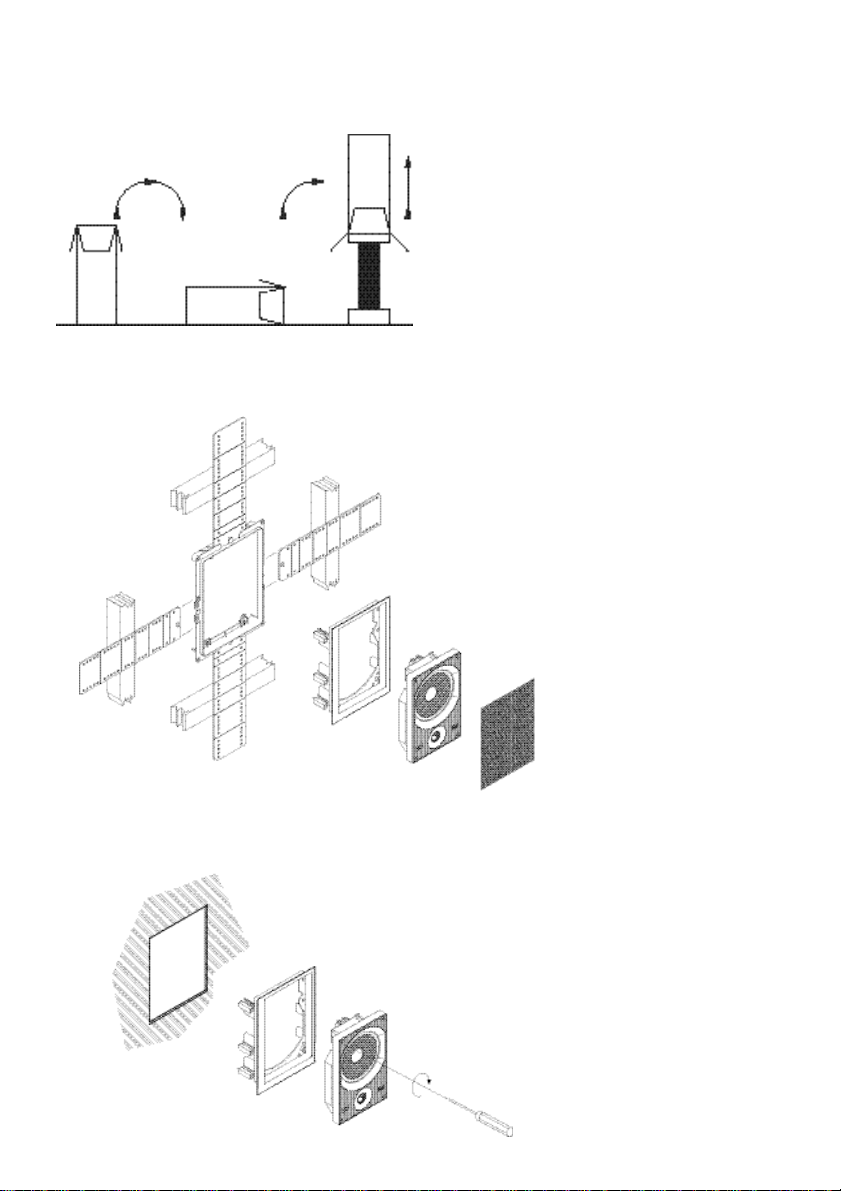
U N PA C K I N G
( F i g u re 1)
• Fold the top carton flaps right back and
i n v e rt the carton and contents.
• Lift the carton clear of the contents.
• Remove the inner packing
f rom the pro d u c t .
Check the contents for:
• 2 x Baffle with drive units and on-board
a m p l i f i e r s
• 2 x Speaker grille scrims
• 8 x Machine screws (for fixing baffles to
wall frame)
We suggest you retain the packaging for future
use. Remove the grilles from the frames and, to
avoid damage, keep them in their plastic bags
(and preferably in the carton) away from the
work area until you are ready to fit them.
DAMPING THE CAV I T Y
A foam pad is supplied to damp the area behind
the drive units. In addition, loosely fill the whole
section of the wall cavity with wadding.
F i b reglass and mineral wool matting supplied for
heat insulation are suitable, but not closed cell
foam or expanded polystyrene. Check that there
is no debris that may fall into the speaker.
I M P O RTA N T: YOU SHOULD CHECK THAT THE
I N S TA L L ATION ITSELF AND THE MATERIALS YOU
USE MEET THE LOCAL FIRE AND BUILDING
R E G U L AT I O N S .
FITTING THE SPEAKER
( F i g u re 2 & 3)
Note: The assembly should be installed with the
tweeter at the bottom.
O ffer up the baffle assembly to the frame and
attach the cables as described in the CASA
installation manual. To avoid rattles, tie down
loose cable near the speaker with clips, mastic
or tape.
Feed the baffle assembly into the frame and
using the screws provided (4 – one in each
c o rner) secure it to the wall frame. Before fitting
the grille, check the operation of all the
loudspeakers in the installation. Remove the
p rotective covers from the tweeters domes. When
you are satisfied that the installation is perf o rm i n g
c o rre c t l y, lay a scrim into each grille and push all
the grilles into the wall frames.
CUSTOMI SIN G
The frame and grille have paintable white semimatte finish, ready if necessary to be re - f i n i s h e d
to match you own decor. Decorate before the
b a ffle is fitted.
If the grille is to be re-finished remove the infaRed “eye” by removing the rubber retaining ring refit before fitting the grille.
Do not paint the baffle or drive unit area it
should be removed if the frame/grille is to be re decorated at a later date.
Page 4

D e s c r i p t i o n
D r i ve units
Amplifier powe r
F r equency range
F r equency response
C r o s s over freq u e n c y
I n p u t
Frame size
Cut-out size without
p r e - m o u n t
Cut-out size
with pre-mount
Min depth req u i r e d
Net we i g h t
S t a n d by powe r
AW M ™ 6 5 0
2-way active wall mount speaker system
1 x 150mm (6in) Kevlar bass/mid unit
with cast basket
1 x 25mm (1in) Aluminium dome HF
equipped with Nautilus™ tube
2 x 50W
-6dB at 42Hz and 30kHz
47Hz - 20kHz ±3dB
3 . 5 k H z
Balanced, 5VRMS sensitivity,
500k impedance
Height: 309mm (121/8i n )
Width: 216 (81/2i n )
Height: 281mm (11in)
Width: 186mm (73/8i n )
Height: 289mm (113/8 i n )
Width: 193mm (75/8i n )
99mm (37/8in) from wall surf a c e
2.5kg
+/- 24V active, +/- 12V passive
<2W in standby
Kevlar is a re g i s t e red trademark of DuPont. E & OE.
B&W Loudspeakers Ltd. re s e rves the right to amend details of the specification without notice in line with technical developments.
B&W Loudspeakers Ltd, Meadow Road, Wo rthing, BN11 2RX Tel: +44 (0) 1903 524801 Fax: +44 (0) 1903 524725
B&W Loudspeakers of America, 54 Concord Street, North Reading, MA 01864-2699, USA
Copyright © B&W Loudspeakers Ltd. Printed in England.
Tel: (1978) 664 2870 Fax: (1978) 664 4109
h t t p : / / w w w. b w s p e a k e r s . c o m
 Loading...