

OWNER’S MANUAL
ASW™500
ii
Fig. 1
Fig. 2
ASW™500
ASW™500
iii
Fig. 3
Fig. 4
ASW™500
ASW™500

Figure 5
ASW™500 Owner’s manual
English ...............................1
Français..............................3
Deutsch ..............................5
Español ..............................7
Português ............................9
Italiano.............................11
Nederlands .......................12
Dansk.........................................14
Ελληνικά
....................................15
Русский
......................................17
ASW™500
iv

1
Safety Instructions
Caution:
To reduce the risk of electric shock, do not
remove the back panel. No user-serviceable
parts inside.Refer servicing to qualified
personnel.
Explanation of Graphical Symbols
The lightning flash within an equilateral triangle is
intended to alert you to the presence of
uninsulated “dangerous voltage” within the product’s
enclosure that may be of sufficient magnitude to
constitute an electric shock to persons.
The exclamation point within an equilateral
triangle is intended to alert you to the presence
of important operating and maintenance
(servicing) instructions in the literature
accompanying the appliance
1 Read Instructions – All the safety and
operating instructions should be read before
the appliance is operated.
2 Retain Instructions – The safety and operating
instructions should be retained for future
reference.
3 Heed Warnings – All warnings on the
appliance and in the operating instructions
should be adhered to.
4 Follow Instructions – All operating and use
instructions should be followed.
5 Water and Moisture – The appliance should
not be used near water – for example, near
a bathtub, washbowl, kitchen sink, laundry
tub, in a wet basement, or near a swimming
pool and the like.
6 Carts and Stands – The appliance should be
used only with a cart or stand that is
recommended by the manufacturer.
7 Wall or Ceiling Mounting – The appliance
should be mounted to a wall or ceiling only
as recommended by the manufacturer.
8 Ventilation – The appliance should be
situated so that its location or position does
not interfere with its proper ventilation. For
example, the appliance should be used with
the amplifier panel vertical: it should not be
situated on a bed, sofa, or similar surface
that may block the ventilation of the amplifier;
or placed in a inadequately ventilated builtin installation, such as a bookcase or
cabinet, that may impede the flow of air to
the rear-mounted amplifier panel.
9 Heat – The appliance should be situated
away from heat sources such as radiators,
heat registers, stoves, or other appliances
that produce heat.
10 Power Sources – The appliance should be
connected to a power supply only of the
type described in the operating instructions
or as marked on the appliance. Models for
use with 100-120V power supplies are fitted
with a polarised plug which should be used
only with an approved polarised receptacle.
To prevent electric shock, match wide blade
of plug to wide slot and fully insert to
prevent blade exposure.
11 Grounding or Polarisation – The appliance
should not be grounded. When using an
extension power-supply cord or a powersupply cord other than that supplied with the
appliance, it should be 2-core, fitted with the
appropriate moulded-on plugs and carry
safety approval appropriate to the country
of use.
12 Power Cord Protection – Power-supply cords
should be routed so that they are not likely
to be walked on or pinched by items placed
on or against them, paying particular
attention to cords at plugs, convenience
receptacles and the point where they exit
from the appliance.
13 Cleaning – The appliance should be
cleaned only as recommended by the
manufacturer.
14 Non-use Periods – The power cord of the
appliance should be unplugged from
the outlet when left unused for a long
period of time.
15 Object and Liquid Entry – Care should be
taken so that objects do not fall and liquids
are not spilled into the enclosure through
openings.
16 Damage Requiring Service – The appliance
should be serviced by qualified personnel
when:
a The power-supply cord or the plug has
been damaged; or
b Objects have fallen, or liquid has been
spilled into the appliance; or
c The appliance has been exposed to rain; or
d The appliance does not appear to operate
normally, or exhibits a marked change in
performance; or
e The appliance has been dropped, or the
enclosure damaged.
17 Servicing – The user should not attempt to
service the appliance beyond that described
in the operating instructions. All other
servicing should be referred to qualified
service personnel.
Warnings:
To prevent fire or shock hazard, do not expose
this equipment to rain or moisture.
Observe all warnings on the equipment itself.
To avoid electrical shock, do not open the
enclosure or remove the amplifier from the
rear panel. There are no user-serviceable
parts inside. Refer all service questions to an
authorised B&W dealer.
To prevent electric shock, do not use this
(polarised) power plug with an extension cord
receptacle or other outlet unless the blades can
be fully inserted to prevent blade exposure.
Ensure that the voltage indicated on the amplifier
panel matches that of the power supply.
The mains fuseholder is located on the back
panel of the amplifier module. Replacement fuse
must be of the same type and rating as supplied.
The equipment should not be earthed (grounded).
Important for UK only:
The wires in this mains lead are coloured in
accordance with the following code:
blue: neutral
brown: live
As the colours of the wires in the mains lead
of this apparatus may not correspond with the
coloured markings identifying the terminals in
your plug, proceed as follows:
The terminal in the plug which is marked
with the letter E, or by the earth symbol, or
coloured green or green and yellow must be
left unconnected.
The wire which is coloured blue must be
connected to the terminal which is marked
with the letter N or coloured black.
The wire which is coloured brown must be
connected to the terminal which is marked
with the letter L or coloured red.
Do not walk the unit on its conical feet as this
may impair the fixing to the cabinet and cause
damage.

2
Introduction
Thank you for purchasing the B&W ASW™500
Active Subwoofer.
Since its foundation in 1966, the continuing
philosophy of B&W has been the quest for
perfect sound reproduction. Inspired by the
company’s founder, the late John Bowers, this
quest has entailed not only high investment in
audio technology and innovation but also an
abiding appreciation of music and the demands
of film sound to ensure that the technology is put
to maximum effect.
The ASW™500 has been designed for Home
Theatre installations and to augment the bass
performance of ‘full range’ speakers in stereo
audio use. Adding the subwoofer to your
system not only extends the bass to lower
frequencies, it improves the midrange clarity
by reducing the low-frequency demands on
your existing speakers.
The subwoofer is magnetically shielded for use
close to a television screen.
Please read through this manual fully before
using the subwoofer. All sound installations
require some planning and experimentation if
you are to get the best out of the products used
and this manual will guide you in this process.
As the subwoofer is connected to the electricity
power supply, it is important that you familiarise
yourself with the safety instructions and heed
all warnings.
Keep this manual in a safe place for future
reference.
B&W loudspeakers are distributed to over
50 countries world-wide and we maintain an
international network of carefully chosen and
dedicated distributors. If you have a problem
which your dealer cannot resolve, our distributors
will be more than willing to assist you.
Unpacking
To avoid damage to the cabinet (and to minimise
strain to yourself) when unpacking, we suggest
that you adopt the following procedure:
• Remove any staples from the open flaps
of the carton.
• Fold the open flaps right back and invert
the carton and contents.
•
Lift the carton away from the product.
•
Remove the upper layer inner packing to reveal
the base of the cabinet.
• Open the polythene bag and turn the cabinet
right way up.
We recommend that you retain the packaging
for future use.
Positioning the ASW™500
Because the ASW™500 produces only very low
notes, positioning is easier than for full-range
speakers. Best results are obtained if the
ASW™500 is placed between the front
speakers. If you use two ASW™500s then it is
best to put one near each front speaker.
The ASW™500 is supplied with conical feet that
raise the base of the cabinet clear of the floor to
allow the down facing port to operate correctly.
Do not reduce this clearance or bass
performance will be degraded.
If the ASW™500 is to be used in a confined
space (e.g. in custom furniture), the space must
be ventilated to allow sufficient air to circulate
and cool the unit. Depending on the volume of
the enclosed space, it may be necessary to
provide ventilation into the room. Ask your
dealer for advice.
Electrical connections
Disconnect all sound system equipment from the
power supply until the signal connections have
been made and checked. This avoids the risk of
damage whilst connections are made or broken.
The ASW™500 accepts inputs and outputs at
either line level (RCA Phono sockets) or at
speaker level.
However, you must not use a mixture of line level
and speaker level connections in the same
installation.
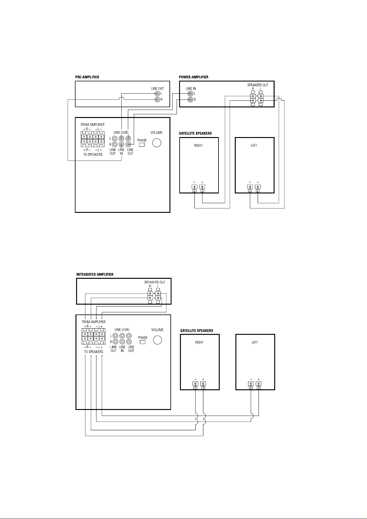
Stereo Audio (Using Line Level
Connections)
(figure 1)
This is the preferred method, and is suitable for
use when you have a separate pre-amplifier and
power amplifier or an external link between the
pre- and power amplifier sections in an
integrated amplifier.
Connect the pre-amplifier left and right line level
output socket(s) to the left and right LINE IN
socket(s) of the ASW™500 and the same
channel LINE OUT socket(s) of the ASW™500
to the line level input socket(s) of the power
amplifier (figure 1).
In both cases, the satellite speakers are
connected to the power amplifier output in the
normal way. However, the signal fed to them
now has the deep bass removed.
Stereo Audio (Using Speaker Level
Connections)
(figure 2)
Use this method when you have an integrated
amplifier with no access to a line level signal.
Connect the speaker level outputs of the power
amplifier to the relevant channel INPUT FROM
AMPLIFIER spring terminals of the ASW™500,
taking care to connect positive to positive and
negative to negative (figure 2). Connect the
satellite speakers to the relevant channel
OUTPUT TO SPEAKERS terminals of the
ASW™500.
With this method of connection, the ASW™500
drive unit is still powered by its own internal
amplifier and the signal fed to the satellite
speakers has the deep bass removed.
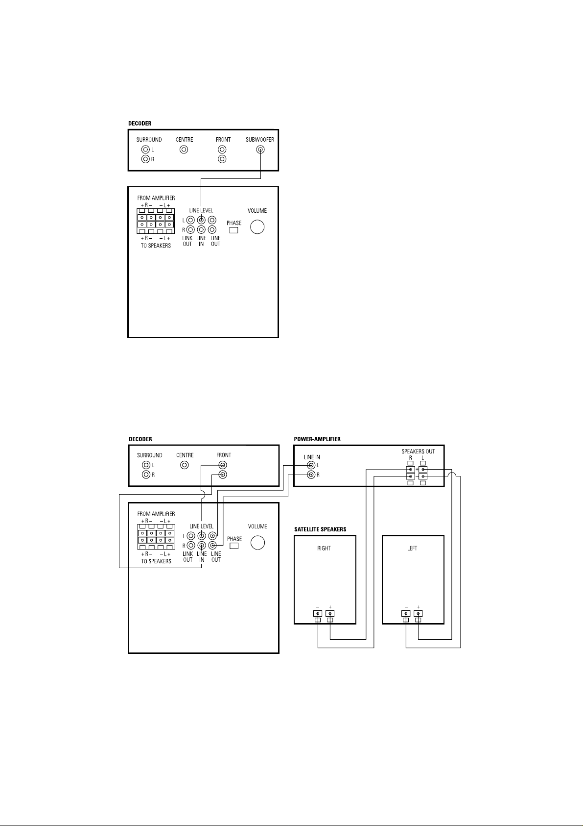
Home Theatre (figures 3, 4 & 5)
If your decoder has a separate subwoofer
output, connect it to one channel only (left or
right) LINE IN socket (for line level) or FROM
AMPLIFIER terminals (for speaker level) of the
ASW™500 and feed the left and right front
speakers directly from the decoder in the normal
way (not via the ASW™500), using a separate
power amplifier if necessary (figure 3).
If your decoder has no dedicated subwoofer
output, connect the ASW™500 to the left and
right front outputs of the decoder and your left
and right front speakers via the ASW™500,
using either the LINE IN/LINE OUT sockets with
separate power amplifiers (figure 4) or the
FROM AMPLIFIER/OUTPUT TO SPEAKERS
terminals (figure 5) in the same manner as
described above for stereo amplifiers.
Using more than one ASW™500
Any number of ASW™500 units can be daisy
chained together in either two-channel mono or
single-channel mode. Using two or more units in
a single installation can improve performance in
the following ways:
• Cope with larger spaces.
• Enable greater maximum sound output – often
useful for effectively reproducing special effects
in Home Theatre applications.
If using line level connections, connect up the
first ASW™500 as described above and then
connect its LINK OUT socket(s) to the
corresponding LINE IN socket(s) of the second
ASW™500. Continue this process as required
for more units.
If using speaker level connections, connect the
first ASW™500 as described above and
connect the FROM AMPLIFIER terminals of the
second ASW™500 to either the corresponding
power amplifier output terminals or the
corresponding FROM AMPLIFIER terminals on the
first ASW™500, whichever is more convenient.
Double Check the Connections
Before auditioning the sound quality of your new
installation and fine tuning it, double check the
connections.
• The phasing is correct – There should be no
positive to negative connections (this applies to
speaker level interconnects). If something is out
of phase you may get a fuzzy sound with an
imprecise and floating image, a lack of bass
or a combination of the two.
• There are no left to right mix-ups – This can
result, for example, in the orchestra being the
wrong way round or, more disastrously, sounds
on your home theatre going in the opposite
direction to the action on the screen.

3
•
Connect the power cord to the power outlet –
we recommend that you switch the ASW™500
on before any power amplifiers receiving
signals from it. Similarly switch off the
ASW™500 last.
Fine Tuning the System
Set the system up in the preferred position and
play some music with a continuous bass content.
Listen with the phase switch in both positions.
The correct one is that which gives the fullest
bass. When using more than one ASW™500,
ensure that each one has its phase switch set
the same way.
If at any time you make changes to the
amplification of the system such that you change
from speaker to line level connections, it is worth
checking the phase setting again.
Set the loudness of the ASW™500 relative to
the satellite systems to your liking. Use a wide
variety of programme material to get an average
setting. One that sounds impressive on one piece
may sound overpowering on another.
If you get problems with uneven bass it is worth
experimenting with the placement of the
ASW™500. What may seem like small changes
in position – 15cm (6in) or so – can have a
profound effect on the sound.
If you alter the position of the ASW™500
appreciably, you should check the level setting
on the subwoofer amplifier, but only after resetting the phase correctly.
Taking Care of your ASW™500
The cabinet normally only requires dusting. If you
wish to use an aerosol cleaner, remove the grille
first by gently pulling it away from the cabinet.
Spray onto the cleaning cloth, not directly onto
the cabinet. The grille fabric may be cleaned
with a normal clothes brush after removing the
grille from the cabinet.
Avoid touching the drive unit, as damage may
result.
Do not use the ASW™500 as a table. When in
use, objects left on top of the ASW™500 are
liable to rattle.
In particular, avoid the risk of liquids being
spilled (e.g. from drinks or vases of flowers).
If the system will be out of use for a long period,
disconnect the ASW™500 from the power
supply.
FRANÇAIS
Avertissements :
Pour éviter tout risque d’incendie ou
d’électrocution, n’exposez jamais cet appareil à
la pluie ou même a l’humidité.
Observez tout signe anormal pouvant provenir
du subwoofer lui-même, n’ouvrez jamais
l’enceinte et ne sortez pas l’amplificateur de son
logement; vous n’y trouverez aucun réglage utile.
En cas de problème renseignez-vous,
préalablement à toute intervention, auprès
d’un véritable revendeur spécialiste de la
marque B&W.
Pensez que vous risquez l’électrocution si vous
n’enfoncez pas complètement les pôles de
la prise d’alimentation, surtout lorsque
vous employez un prolongateur ou un
raccord électrique.
Assurez-vous que la tension indiquée sur
l’appareil correspond bien a celle de votre
réseau électrique.
Les fusibles d’alimentation se trouvent sur le
panneau du module d’amplification. En cas
de remplacement, n’utilisez jamais de fusibles
d’un type différent ; vérifiez que les valeurs
indiquées sur les nouveaux fusibles sont
parfaitement identiques à celles qui figurent sur
les modèles d’origine.
Cet appareil ne doit pas être raccordé à
la terre.
Introduction
Nous vous remercions d’avoir choisi le
Subwoofer actif B&W ASW™500.
Depuis la création de notre entreprise en 1966,
la base invariable de notre philosophie a toujours
été la recherche de la perfection absolue.
Inspirée par son fondateur, le regretté John
Bowers, cette extraordinaire aventure qu’est la
quête de l’absolu, n’a pas seulement débouché
sur de très lourds investissements consacrés à la
recherche et à l’innovation, mais aussi sur une
profonde connaissance de la musique et des
spécificités du son cinématographique. Cette
connaissance nous permet de nous assurer que
la technologie sera toujours utilisée au service
du meilleur résultat possible et non à la
technique pour la technique.
L’ASW™500 n’a pas seulement été étudié
pour les installations de Home Cinéma, il
conviendra naturellement à la reproduction de
haute qualité des très basses fréquences de toute
chaîne sonore. Ce subwoofer apporte, en plus
d’une extension spectaculaire de la réponse vers
l’extrème-grave, une amélioration non
négligeable de la clarté
de reproduction du médium, grâce à la réduction
du travail demandé aux enceintes principales.
L’ASW™500 est blindé magnétiquement.
Vous pouvez donc l’utiliser à proximité de
votre téléviseur.
Veuillez lire attentivement et totalement cette
notice avant d’utiliser votre subwoofer. Toute
installation sonore recquiert un minimum
d’attention et d’expérimentation quand on
souhaite en tirer le meilleur parti ; ce manuel
vous guidera dans cette voie.
Avant de raccorder le subwoofer au réseau
électrique, il est important que vous ayez pris
connaissance des consignes de sécurité pour
que vous puissiez tenir compte de tout signe
anormal ou alarmant.
Rangez ce guide de telle façon que vous
puissiez le retrouver facilement pour de
futures consultations.
La distribution de B&W est assurée dans plus de
50 pays à travers le monde. Nous entretenons
un réseau d’importateurs sélectionnés avec la
plus grande attention. Quelque soit le problème
qu’un revendeur ne saurait régler, n’hésitez
jamais à contacter votre agent national afin qu’il
puisse vous assister.
Déballage
Pour éviter d’endommager le caisson (et réduire
vos propres efforts), nous vous recommandons de
procéder de la manière suivante :
•
Otez toutes les agrafes après ouverture des
volets du carton externe.
•
Ouvrez les volets, puis retournez complètement
le carton et son contenu.
• Levez le carton pour dégager son contenu.
• Enlevez la base de protection, pour accéder
au solcle du caisson de grave.
• Ouvrez le sac en plastique, puis retournez le
caisson de grave.
Nous vous recommandons de conserver
l’emballage pour tout transport ultérieur du
caisson de grave.
Position du caisson de grave
Parce que le ASW™500 ne reproduit que les
notes les plus graves, son positionnement
présente beaucoup moins de contraintes que
celui des enceintes traditionnelles. Le meilleur
résultat sera obtenu en le plaçant entre les deux
enceintes frontales. Si vous utilisez deux caissons
ASW™500, le plus simple est d’en placer un
auprès de chaque enceinte.
L’ASW™500 est livré avec des pieds coniques
qui permettent de surélever la base du caisson et
donc au système d’évent de fonctionner
correctement. Il est impératif de ne pas réduire
l’espace ainsi créé avec le sol, sous peine de
dégrader les résultats de manière plus ou moins
importante.
Si le caisson ASW™500 doit être utilisé dans
un espace confiné (par exemple intégré sous ou
dans un meuble), cet espace doit être ventilé
pour permettre une circulation d’air suffisante,
destinée à bien refroidir l’appareil. En cas de
doute, n’hésitez pas à demander conseil à votre
revendeur agréé.

Description
Drive units
System frequency response
Amplifier
Low-Pass Filter
High-Pass Filter
Internal Volume
Dimensions
Net Weight
Finish
ASW™500
B&W Loudspeakers Ltd. reserves the right to amend details of the specification without notice in line with technical developments.
Copyright © B&W Loudspeakers Ltd. Printed in England.
B&W Loudspeakers Ltd, Meadow Road, Worthing, BN11 2RX Tel: +44 (0) 1903 524801 Fax: +44 (0) 1903 524725
http://www.bwspeakers.com
Active vented-box subwoofer system
One 250mm (10in) dia long-throw with pressed fibre
cone and magnetic shielding
-3dB at 32Hz and 80Hz
Discrete MOSFET
Power output: 70W continuous
Input Impedance: 22kΩ
Signal/Noise: 96dB
Functions: Input Level
Phase 0º/180º
Inputs: Line In (RCA Phono)
Speaker Level In (Spring Terminals)
Outputs: Line Out (RCA Phono)
Link Out (RCA Phono)
Speaker Level Out (Spring Terminals)
Active 2nd-order at 80Hz
Line Level: Passive 1st-order at 80Hz (47kΩ load)
Speaker Level: Passive 1st-order at 80Hz into 8Ω resistor
(Response of passive filters
dependent on load impedance)
35 litres (1.24 cu ft)
Height: 415mm (16.3 in)
Width: 353mm (13.9 in)
Depth: 401mm (15.8 in)
12kg (26.5lb)
Cabinet: Black Ash vinyl
Grille: Black
I5045
 Loading...