

Page 1
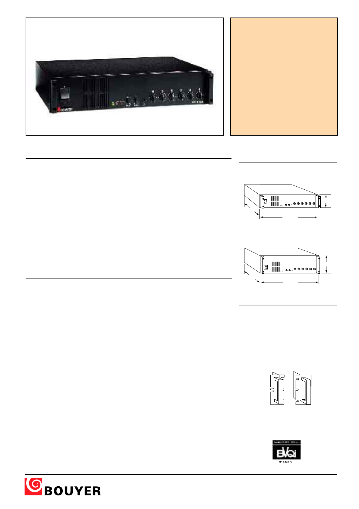
I
0
123456
425 mm
345 mm
92 mm
I
0
123456
425 mm
345 mm
135 mm
ASS 33006666
A
I - DESCRIPTION
Les AS 3066, AS 3126 et AS 3246 sont
des amplificateurs mélangeurs de 60W,
120W et 240W à six entrées.
Cinq de ses 6 entrées sont commutables en
MIC ou en AUX. La sixième peut recevoir
une source auxiliaire stéréo ou mono.
Huit modes de priorité configurables permettent de gérer les entrées.
Un carillon à deux tons peut être attribué
aux 3 premières entrées.
Ils possèdent les fonctions : Noise gate Sortie 0dB - Prises d’insertion.
Ces appareils 2U et 3U 19” (Fig. I) sont utilisables sur le secteur 230V et peuvent être
intégrés dans une baie en utilisant les poignées AZ7ou AZ8, en option (Fig. II).
I - DESCRIPTION
The AS 3066, AS 3126 et AS 3246 are
mixer amplifiers of respectively 60W, 120W
and 240W with six inputs.
Five of them may be individually set to AUX
or MIC. The sixth input is intended to be
connected to a stereo or mono AUX source.
Input priorities may be selected among eight
modes.
A two-tone chime is provided for inputs 1
to 3.
They have the functins : Noise gate - Sortie
0dB - Prises d’insertion.
These mixer amplifiers are power supplied
to 230V mains and can be mounted in a 19”
rack by using handles AZ7 or AZ8 (optional)
(Fig. II).
ASS 3311
A
ASS 33
A
266
2
24466
2
AMPLIFICATEURS
MÉLANGEURS, 6 Entrées
60W - 120W - 240W
60W - 120W - 240W
MIXER AMPLIFIERS
6 inputs
AS 3066 - AS 3126
AS 3246
II - CARACTÉRISTIQUES TECHNIQUES II - TECHNICAL SPECIFICATIONS
•
Puissances de sortie
AS 3066 .......................................... 60W RMS
AS 3126........................................ 120W RMS
AS 3246........................................ 240W RMS
• Distorsion .................................... < 1% à 1kHz
• Bande passante (-3dB) ...... 65 - 17 000 Hz
(entrée AUX)
• Correction de tonalité
Graves........................................ ±7dB à 100 Hz
Aigus .......................................... ±8dB à 10 kHz
Rapport signal/bruit ............................ >80dB
• Entrées
- 5 entrées symétriques ............Mic -60dB
(alimentation fantôme) ou
- 1 entrée double asymétrique .......... -10dB
• Carillon ...................................................... 2 tons
• Prise insertion .......................................... 0 dB
• Sorties
Ligne........................................ 0 dB symétrique
100V (AS 3066).................................... 166 Ω
100V (AS 3126) ...................................... 83 Ω
100V (AS 3246) ...................................... 42 Ω
• Alimentation
Secteur ............ 230V - 50/60 Hz avec terre
• Consommation
• Dimensions.......................................... (Fig. I)
• Poids................................................ 8 - 9 - 12 kg
• Option.............. Poignées AZ7ou AZ8 (Fig.II)
AS 3066................................................ 190 VA
AS 3126................................................ 390 VA
AS 3246................................................ 770 VA
Aux -10dB
• Output powers
AS 3066 .......................................... 60W RMS
AS 3126........................................ 120W RMS
AS 3246........................................ 240W RMS
• Distortion .................................. < 1% at 1kHz
• Bandwidth (-3dB) ................ 65 - 17 000 Hz
(AUX input)
• Tone corrector
Bass .......................................... ±7dB at 100 Hz
Treble........................................ ±8dB at 10 kHz
Signal to noise ratio.............................. >80dB
• Inputs
- 5 balanced input ..........................Mic -60dB
(Phantom power supply) or
- 1 dual unbalanced input .................. -10dB
• Chime ...................................................... 2 tones
• Insertion socket........................................ 0 dB
• Outputs
Line.............................................. 0 dB balanced
100V (AS 3066).................................... 166 Ω
100V (AS 3126) ...................................... 83 Ω
100V (AS 3246) ...................................... 42 Ω
• Power supply
Mains ................ 230V - 50/60 Hz with earth
• Consumption
AS 3066................................................ 190 VA
AS 3126................................................ 390 VA
AS 3246................................................ 770 VA
• Dimensions ........................................ (Fig. I)
• Weight ............................................ 8 - 9 - 12 kg
• Optional ...... AZ7
or
AZ8 handles set
Aux -10dB
Fig. I
Ce document n'est pas contractuel; toute modification pouvant intervenir sans préavis / This document is not legally binding, we reserve the right to modify descriptions and specifications without notice.
AZ 7 /AZ 8 - Jeux de poignées
Handles set AZ 7 / AZ 8
Fig. II
(Fig.II)
Code 596 285 - 10/05
480 avenue de Paris • 82000 MONTAUBAN • FRANCE
Tél : 33 (0)8 92 70 20 82* (*0,34 € la minute TTC) • Fax : 33 (0)5 63 03 08 26 • http://www.bouyer.com
Page 2
ENTREES
INPUTS
ATTENTION :
débrancher le
secteur avant
d'ouvrir
CAUTION :
disconnect
from supply
before opening
AUX
MIC
Configuration
AUX / MIC
1 2 3 4 5 6
Télécom.
Remote
3
1
5
2
4
Entrée symétrique
Balanced input
3
1
5
2
4
Sortie symétrique
Balanced output
CHIME
CARILLON
1 2 3 4 5 6 7 8
IN
{
PRIORITY
MODE
1 2 3 4 5 6
AUX
SORTIE
OUTPUT
0dB
{
PRIORITY
MODE
INSERTION
SORTIES
OUTPUTS
0
100V
230V
50/60Hz
11 12 13 14 15 16 17 18 19 21 22
ATTENTION :
SORTIE DE
VENTILATION
CAUTION :
AIR COOLING
OUTPUT
MONTAUBAN -FRANCE
BOUYER
Off
Noise
gate
Auto
20
III - PRESENTATION III - PRESENTATION
I
0
AS 3126
1
2
ON
MODUL
FAULT
3 4 5
1
0
2
4 6
8
10
2
0
2
4 6
8
10
3
0
2
4 6
8
10
4
0
2
4 6
8
10
5
0
4 6
8
10
2
6
0
4 6
8
10
2
-10
+10
-10
+10
BASS
TREBLE
6
7
0 0
{
8
9
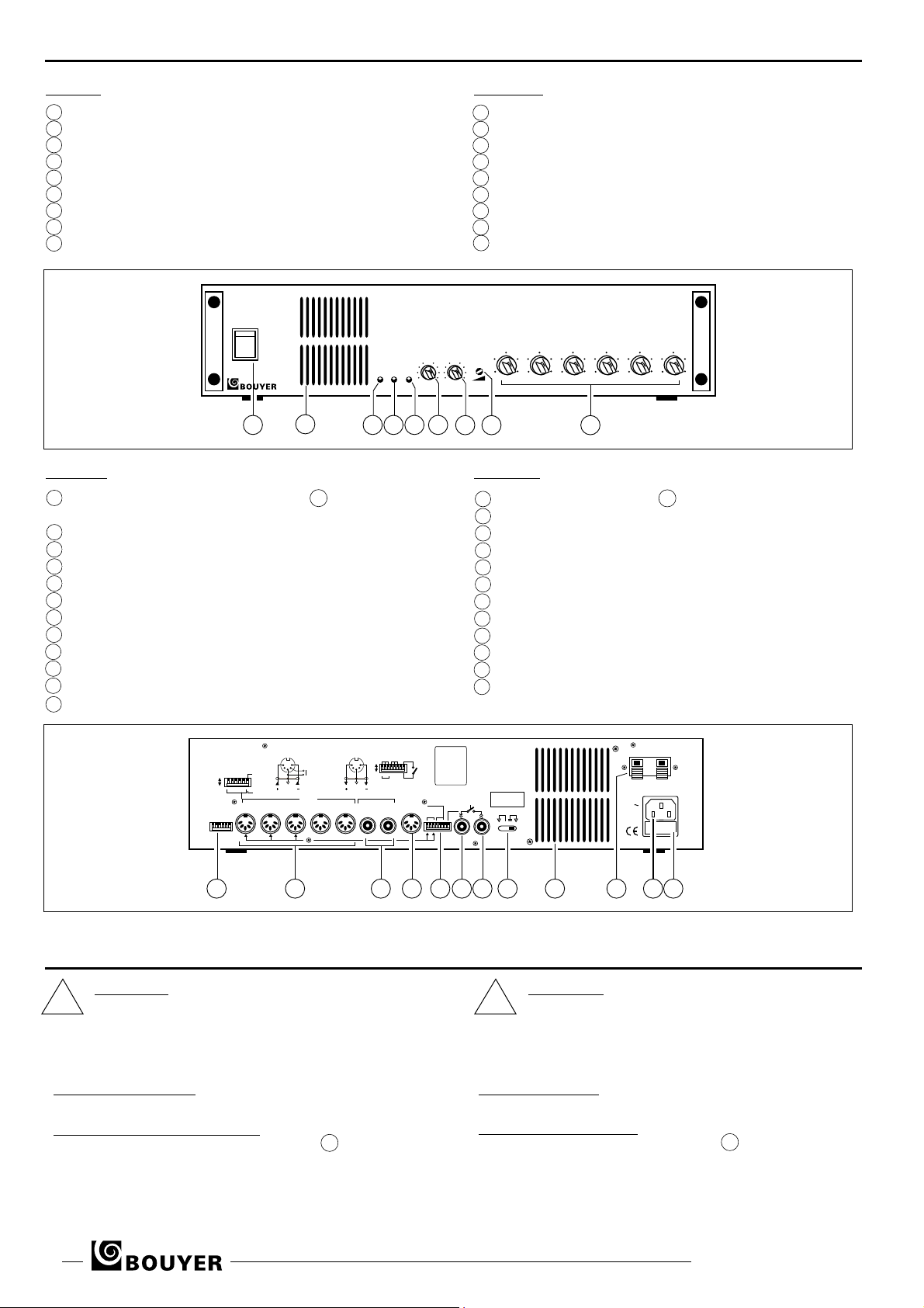
A l'avant (Fig. III)
1 Interrupteur de mise sous tension
2 Grille de ventilation
3 Voyant lumineux de fonctionnement
4 Voyant lumineux de modulation
5 Voyant lumineux de température excessive
6 Bouton de réglage tonalité grave
7 Bouton de réglage tonalité aiguë
8 Réglage du volume carillon
9 Boutons de réglage volume des entrées
Fig. III
A l'arrière (Fig. IV)
11 Inverseurs pour configuration des entrées 12 AUX ou MIC et
“Noise gate” (Seuil de modulation)
12 Entrées DIN symétriques AUX ou MIC
13 Prises Cinch AUX asymétriques, droite-gauche
14 Sortie DIN symétrique 0dB
15 Inverseurs carillon et sélection des priorités
16 Prise Cinch d’insertion sortie
17 Prise Cinch d’insertion entrée
18 Inverseur de boucle de masse
19 Grilles de ventilation
20 Bornier de sortie haut-parleurs, ligne 100V
21 Prise secteur 230V avec terre
22 Fusible secteur
Front panel (Fig. III)
1 ON/OFF switch
2 Ventilation grille
3 ON indicator light
4 Modulation indicator light
5 Overheat indicator light
6 Bass tone control
7 Treble tone control
8 Chime volume control
9 Input volume controls
Rear panel (Fig. IV)
11 - AUX/MIC switch of inputs 12 and noise gate
12 - AUX/MIC balanced DIN inputs
13 - AUX unbalanced Cinch sockets, right-left
14 - 0dB balanced DIN output
15 - Chime switch and priority settings
16 - Output insertion Cinch socket
17 - Input insertion Cinch socket
18 - Ground loop switch
19 - Ventilation grilles
20 - 100V loudspeaker output terminal
21 - 230V mains socket with earth
22 - Mains supply fuse
Fig. IV
IV - INSTALLATION IV - INSTALLATION
ATTENTION :
! !
L’appareil ne doit pas être exposé aux chutes d’eau et aux
éclaboussures.
Avant toute intervention dans l’appareil, déconnecter le
câble secteur.
Après l’intervention, refermer l’appareil en vérifiant que le
fil de terre (jaune et vert) est bien connecté.
• Branchement secteur
L’appareil est livré pour un fonctionnement en 230V avec terre.
• Branchement des haut-parleurs
Raccorder la ligne des haut-parleurs à la sortie 20 (Fig.
La puissance totale des haut-parleurs ne doit absolument pas dépasser la puissance de l’amplificateur (60W, 120W ou 240W).
Vérifier que les haut-parleurs installés dans une même zone d’écoute
sont bien branchés “en phase”
Le “Guide de la sonorisation” vous apportera des précisions sur le
choix et l’orientation des haut-parleurs.
IV).
• Mains Connection
The unit is supplied for use with 230V with earth.
• Loudspeaker connection
Connect the loudspeaker line to the output 20 (Fig. IV).
Always ensure that the total loudspeaker load does not exceed
the maximum power of the amplifier
Check that loudspeakers are connected in phase.
Advice on the choice and orientation of loudspeakers can be
found in the guide “Sound Advice”.
2 AS 3066 - AS 3126 - AS 3246
ATTENTION :
The unit is neither water - nor splash proof.
Before any manipulation, disconnect the mains cable.
After manipulation, put back the cover and check that
the “earth” wire (yellow+green) is connected properly.
(60W, 120W or 240W).
Page 3
• Branchement des sources de modulation
Les prises DIN 12 de 1 à 5 sont des entrées symétriques programmables en AUX ou MIC grâce aux inverseurs de 1 à 5 11
• Modulation sources connection 12 and 11
DIN sockets 1 to 5 are balanced inputs. They may be set to AUX
or MIC thanks to switches 1 to 5.
(Fig. IV).
AUX ________________________ Position haute des inverseurs
MIC__________________________ Position basse des inverseurs
En position MIC, une alimentation fantôme est disponible en permanence (Norme Din 45596).
Les 2 entrées Cinch 13 sont des entrées auxiliaires pour une
source stéréo gauche-droite ou une entrée mono.
AUX ______________________________________Upper position
MIC ______________________________________Lower position
In MIC position, phantom power supply is always available (DIN
standard 45 596).
The two Cinch (RCA) sockets 13 allow to connect a stereo or
mono AUX input.
V - UTILISATION V - USE
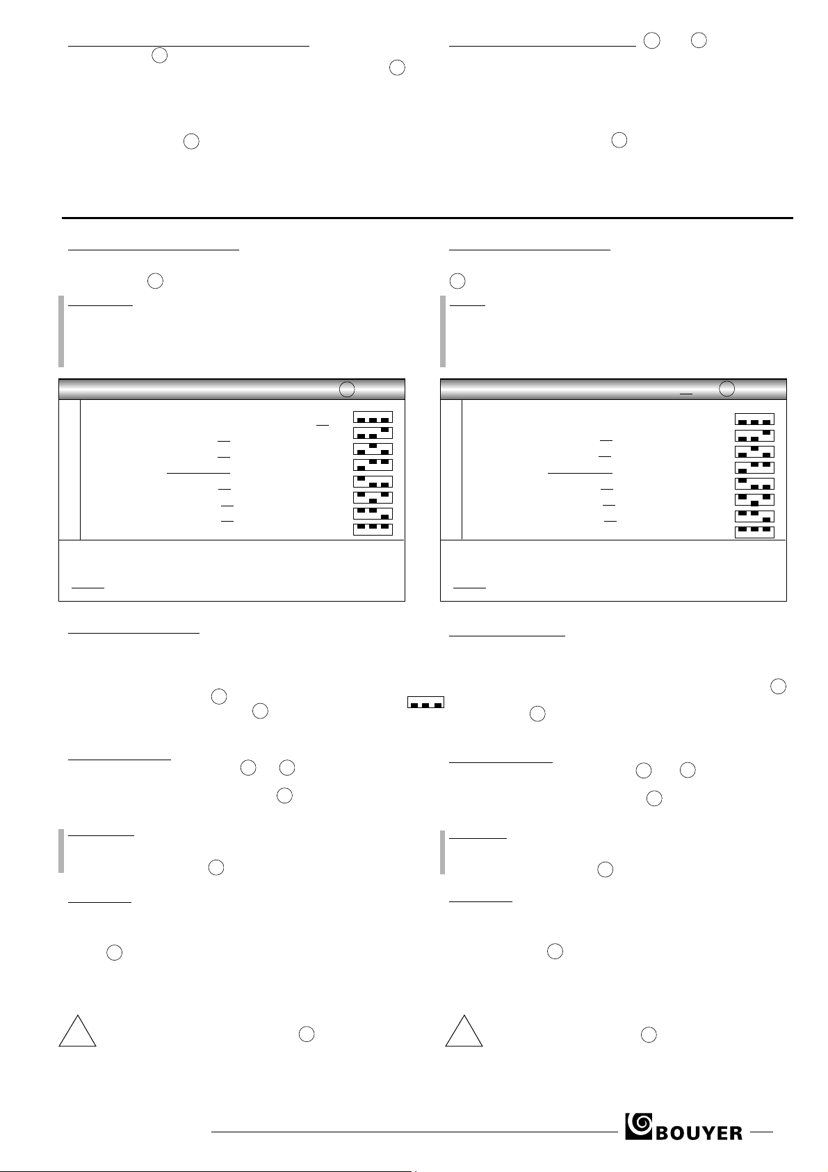
• Modes priorité - entrées 1 à 6
8 configurations de priorité sont disponibles. Pour sélectionner la
configuration choisie, voir tableau ci-dessous, utiliser les inverseurs 4-5 et 6 15 (Fig. IV).
REMARQUE !
Pour le fonctionnement en mode priorité, les sources doivent
délivrer une télécommande - contact entre 2 et 4 de la prise DIN.
Si tel n’est pas le cas, par exemple pour un lecteur CD, le
connecter en entrée 4 ou 5 ou 6 et configurer selon la ligne 5 du
tableau. L’entrée 6 fonctionne toujours sans télécommande.
Priorité Inverseur
15
(Fig. IV)
4 5 6
1 6 entrées en mélange sans télécommande ____
2 5 entrées en mélange avec télécommande E6 __
3 E1 > E2 > E3 > E4 > E5 > E6
4 E1 > E2 + E3 + E4 + E5 + E6 __________________
5 E1 > E2 > E3 + E4 + E5 + E6 __________________
6 E1 > E2 # E3 > E4 + E5 + E6 __________________
7 E1 > E2 # E3 # E4 # E5 > E6__________________
8 E1 # E2 # E3 # E4 # E5 > E6 ________________
Signification des symboles :
E1 + E2 : E1 en mélange avec E2
E1 > E2 : E1 prioritaire sur E2
E1 # E2 : Priorité au premier appelant
E4 … E5 : E4 et E5 fonctionnent sans télécommande
• Carillon - entrées 1-2-3
Sur les entrées 1,2 et 3, les messages d’annonce peuvent être précédé d’un carillon 2 tons. Ce carillon est déclenché par la télécommande (4 et 2 de la prise DIN) de chaque entrée. Pour valider ce
carillon sur chacune des entrées 1,2 et 3, basculer vers le bas l’inverseur correspondant 1-2 et 3 15 (Fig. IV).
Le volume est réglable en face avant 8 (Fig. III). Le carillon ne fonctionne pas avec la configuration de la ligne 1 du tableau de priorité.
• Priority mode - 1 to 6 inputs
8 priority mode configurations are available. To select the desired
configuration, see the board below, and use switches 4, 5 and 6
15 (Fig.IV).
NOTE !
To use in priority mode, the sources must use a remote control
connection between DIN sockets 2 and 4. If this is not the case,
for example for a CD reader, to connect to input 4 or 5 or 6 and
config according to line 5 of the table. Input 6 always works with-
out a remote control.
Priority Switch
1 6 mixing inputs with remote control __________
2 5 mixing inputs without remote control E6 ____
3 E1 > E2 > E3 > E4 > E5 > E6 __________________
4 E1 > E2 + E3 + E4 + E5 + E6 __________________
5 E1 > E2 > E3 + E4 + E5 + E6 __________________
6 E1 > E2 # E3 > E4 + E5 + E6 __________________
7 E1 > E2 # E3 # E4 # E5 > E6__________________
8 E1 # E2 # E3 # E4 # E5 > E6 ________________
Symbols :
E1 + E2 : E1 in mixing with E2
E1 > E2 : E1 taken priority over E2
E1 # E2 : First speaking priority
E4 … E5 : E4 and E5 operates without remote control
• Chime - 1-2-3 inputs
For inputs 1, 2 and 3 announcements may be preceded by a two-
tone chime. This chime is activated by the remote control (DIN sock-
ets 4 and 2) for each input. To validate the chime on each of inputs 1,
2 and 3 set the corresponding number of switches 1, 2 and 3 15
1 2 3
(Fig. IV) to the down position. The volume is adjustable from the front
of the amplifier
Chime does not function with line 1 configuration of the priority board.
8 (Fig. III).
15
(Fig. IV)
4 5 6
• Prises d’insertion
Les prises Cinch “IN” ET “OUT” 16 et 17 (Fig. IV) permettent
d’insérer un appareil, par exemple un équaliseur, dans la chaîne
d’amplification. Dans ce cas l’inverseur 8 15 (Fig. IV) doit être basculé vers le haut (ouvert).
ATTENTION !
Si les prises d’insertion ne sont pas utlisées, l’inverseur 8 doit
être basculé vers le bas, sinon pas de signal en sortie.
L’inverseur n°7 est inactif
15 (Fig. IV).
• Noise-gate
L’appareil est pourvu d’une fonction Noise-gate qui réduit le bruit de
fond sur les haut-parleurs en l’absence de signal de modulation.
Cette fonction peut être supprimée en basculant vers le bas, l’inverseur 6 11 (Fig. IV). Il est parfois nécessaire de supprimer la fonction
Noise-gate, par exemple pour des prises de son avec des microphones éloignés.
En cas d’utilisation avec d’autres appareils reliés à la terre, il
est conseillé de pousser l’inverseur 18 (Fig. IV) vers la
! !
gauche pour éviter des ronflements dûs aux boucles de
masse.
AS 3066 - AS 3126 - AS 3246 3
• Insertion Cinches
The insertion cinches ‘IN’ and ‘OUT’ 16 and 17 (Fig.IV) allow the
addition of other equipment into the amplification chain, for exam-
ple an equaliser. In this case, switch 8 15 (Fig. IV) must be set to
the up position (on).
WARNING !
If the insertion cinches are not used, switch 8 must be set to the
down position, otherwise there will be no output signal.
Switch number 7 is inactive
15 (Fig. IV).
• Noise-gate
The amplifier is provided with a Noise-gate function, which reduces
background noise in the loudspeakers in the absence of a modula-
tion signal. This function can be switched off by setting switch 6 to
the down position 11 (Fig. IV). It is sometimes necessary to switch
off the Noise-gate function, for example for sound sockets with
remote microphones.
When using with earthed equipments, it is recommended
to push to the left the switch 18 (Fig. IV) in order to avoid
ground loop.
Page 4
1
1
2
4
3
VI - PROTECTIONVI - PROTECTION
Surcharge
L’amplificateur est protégé contre les surcharges ou court-circuit en sortie. Si le défaut persiste un échauffement peut produire une coupure de
la modulation. Le voyant 5 (Fig. III) s’allume.
Surchauffe
Le ventilateur se met en service lorsque la température atteint 65°. Si
cette température atteint 85° la modulation se coupe, le voyant 5
s’allume. Vérifier dans ce cas que la grille de ventilation n’est pas obstruée.
Overload
The amplifier is protected against short circuits and overload.
If an overheating condition occurs, the signal is muted.
The indicator 5 (Fig. III)
Overheat
The ventilator of radiators switch on when temperature reach 65°. If
the temperature exceed 85° modulation is cutted, the indicator 5
switches “On”. In this case, check that ventilation grille is not obturated.
switches “On”
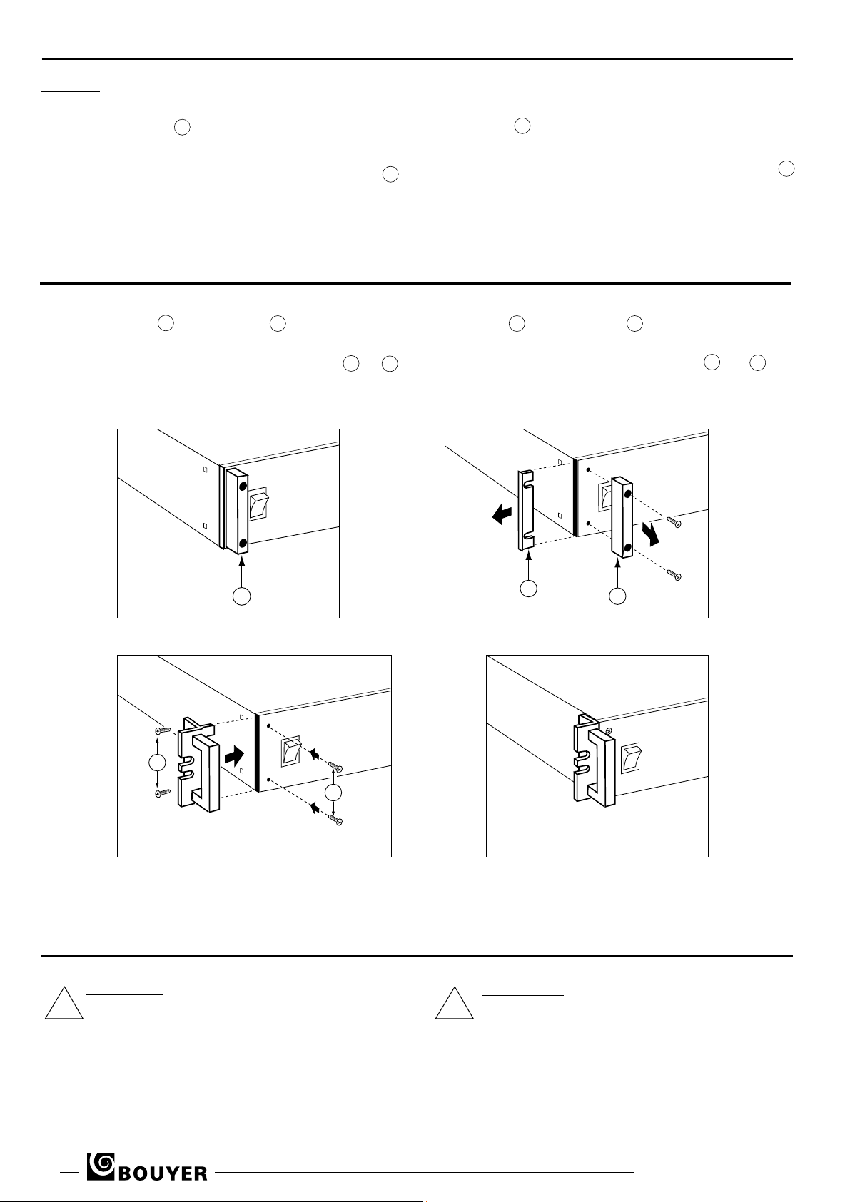
VII - MONTAGE EN RACK VII - RACK MOUNTING
Pour équiper un appareil du jeu de poignées AZ 7 ou AZ 8, commencer
par ôter chaque butée 1 et le cache latéral 2 (Fig. V et VI) qui sont
fixés par les mêmes vis cruciformes.
Installer les poignées en les glissant à la place des caches latéraux
(Fig.VII), puis placer et serrer les vis frontales et latérales 3 et 4
(Fig.VII et VIII).
To fit the AZ 7 or AZ 8 handles onto the AS, first remove the button-protection blocks 1 and the side plates 2 (Fig. V and VI) which are held
in place by the same screws.
Use Philips type screwdriver. Slide the handle brackets into the housings
which hold the side plates. Replace the front screws 3 and 4 and
side screws and tighten them (Fig. VII and VIII).
.
Fig. V Fig. VI
Fig. VII
Fig. VIII
VIII - MAINTENANCE VIII - MAINTENANCE
En cas de panne :
•
Vérifier l’état du fusible et le remplacer si besoin par un
!
fusible de mêmes caractéristiques tel qu’indiqué sur l’appareil.
•
Attendre que l’appareil refroidisse pour s’assurer que la
panne n’est pas due à la protection thermique.
•
Sinon retourner l’appareil à l’usine, ou faire appel à un
dépanneur professionnel.
In case of failure
• Check the status of the fuse and replace them if needed by
!
fuse with the same caracteristics as those indicated on the
product.
• Wait until the product has cooled off, to be sure that the failure is not caused by the thermal relay.
• Otherwise the product has to be sent back to the factory or
repaired by a recognised dealer.
:
4 AS 3066 - AS 3126 - AS 3246
 Loading...