

Land Ranger™
Metal Detector
Owner’s Manual
The Land Ranger™ is a top-of-the line professional metal detector
with high-end features for the serious metal detectorist. A large LCD
panel displays current operating status at all times during operation
in the field. All feaures and functions are highly visible, with no
hidden programming, making your Land Ranger™ easy to use.
◆ Microprocessor-controlled
◆ Programmable operation
◆ Programmable targets
◆ LCD target readout
◆ Touch pad selection
◆ Numbered target values
◆ SMART TRAC ground control
Carefully read this entire manual before attempting to operate
your new Land Ranger™ Metal Detector.

Contents
The Basics of Metal Detecting . . . . . . . . . . . . . . . . . . . . . . . . 1
Metal Types . . . . . . . . . . . . . . . . . . . . . . . . . . . . . . . . . . . . . . . . 1
Discrimination . . . . . . . . . . . . . . . . . . . . . . . . . . . . . . . . . . . . . . 1
Depth Detection . . . . . . . . . . . . . . . . . . . . . . . . . . . . . . . . . . . . . 2
Ground Balancing . . . . . . . . . . . . . . . . . . . . . . . . . . . . . . . . . . . 2
Quick Start . . . . . . . . . . . . . . . . . . . . . . . . . . . . . . . . . . . . . . . . 2
Getting Started . . . . . . . . . . . . . . . . . . . . . . . . . . . . . . . . . . 3
Assembly . . . . . . . . . . . . . . . . . . . . . . . . . . . . . . . . . . . . . . . . . . 3
To assemble the Land Ranger™ . . . . . . . . . . . . . . . . . . . . . . . . . 3
Batteries . . . . . . . . . . . . . . . . . . . . . . . . . . . . . . . . . . . . . . . . . . 4
To install the batteries . . . . . . . . . . . . . . . . . . . . . . . . . . . . . . . 4
To check the batteries . . . . . . . . . . . . . . . . . . . . . . . . . . . . . . . 4
Headphones. . . . . . . . . . . . . . . . . . . . . . . . . . . . . . . . . . . . . . . . 5
To connect and use headphones. . . . . . . . . . . . . . . . . . . . . . . . . 5
Control Panel . . . . . . . . . . . . . . . . . . . . . . . . . . . . . . . . . . . . 7
Probable Target ID fields. . . . . . . . . . . . . . . . . . . . . . . . . . . . . . . 7
Touch pads . . . . . . . . . . . . . . . . . . . . . . . . . . . . . . . . . . . . . . . . 9
LCD Display. . . . . . . . . . . . . . . . . . . . . . . . . . . . . . . . . . . . . . . 10
TARGET Readout. . . . . . . . . . . . . . . . . . . . . . . . . . . . . . . . . . 10
Dials . . . . . . . . . . . . . . . . . . . . . . . . . . . . . . . . . . . . . . . . . . 11
Target Value Reference . . . . . . . . . . . . . . . . . . . . . . . . . . . . . . 12
Basic Operation . . . . . . . . . . . . . . . . . . . . . . . . . . . . . . . . . 13
Turning the Detector ON. . . . . . . . . . . . . . . . . . . . . . . . . . . . . . 13
DISCRIMINATION Mode . . . . . . . . . . . . . . . . . . . . . . . . . . . . . . 13
To accept all targets . . . . . . . . . . . . . . . . . . . . . . . . . . . . . . . . 13
To select PRESET targets. . . . . . . . . . . . . . . . . . . . . . . . . . . . . 14
To select customized targets. . . . . . . . . . . . . . . . . . . . . . . . . . . 15
To adjust sensitivity in DISCRIMINATION mode . . . . . . . . . . . . . . 17
To listen to tones in DISCRIMINATION mode. . . . . . . . . . . . . . . . 17
ALL METAL Mode . . . . . . . . . . . . . . . . . . . . . . . . . . . . . . . . . . . 18
To select ALL METAL mode . . . . . . . . . . . . . . . . . . . . . . . . . . . 18
To adjust sensitivity in ALL METAL mode . . . . . . . . . . . . . . . . . . 19
To adjust detector when ground conditions change. . . . . . . . . . . . 19
To update ground balancing. . . . . . . . . . . . . . . . . . . . . . . . . . . 20
Testing the detector . . . . . . . . . . . . . . . . . . . . . . . . . . . . . . 21
Ground Testing . . . . . . . . . . . . . . . . . . . . . . . . . . . . . . . . . . . 21
Air Testing . . . . . . . . . . . . . . . . . . . . . . . . . . . . . . . . . . . . . . 21
Using the Detector in the Field . . . . . . . . . . . . . . . . . . . . . . 23

Coil Movement . . . . . . . . . . . . . . . . . . . . . . . . . . . . . . . . . . . 23
Pinpointing the target . . . . . . . . . . . . . . . . . . . . . . . . . . . . . . 24
False signals and chatter . . . . . . . . . . . . . . . . . . . . . . . . . . . . 25
Ground Balancing . . . . . . . . . . . . . . . . . . . . . . . . . . . . . . . . . 26
Resetting the detector . . . . . . . . . . . . . . . . . . . . . . . . . . . . . . 26
Detector Applications . . . . . . . . . . . . . . . . . . . . . . . . . . . . . 27
Coinshooting . . . . . . . . . . . . . . . . . . . . . . . . . . . . . . . . . . . . . . 27
Recommended Mode of Operation . . . . . . . . . . . . . . . . . . . . . . 27
Relic Hunting . . . . . . . . . . . . . . . . . . . . . . . . . . . . . . . . . . . . . . 29
Recommended mode of operation . . . . . . . . . . . . . . . . . . . . . . . 29
Jewelry Hunting . . . . . . . . . . . . . . . . . . . . . . . . . . . . . . . . . . . . 31
Recommended mode of operation . . . . . . . . . . . . . . . . . . . . . . . 31
Gold Prospecting . . . . . . . . . . . . . . . . . . . . . . . . . . . . . . . . . . . 32
Recommended mode of operation . . . . . . . . . . . . . . . . . . . . . . . 32
Tips for gold prospecting . . . . . . . . . . . . . . . . . . . . . . . . . . . . 32
Cache Hunting . . . . . . . . . . . . . . . . . . . . . . . . . . . . . . . . . . . . . 33
Recommended mode of operation . . . . . . . . . . . . . . . . . . . . . . . 33
Tips for cache hunting . . . . . . . . . . . . . . . . . . . . . . . . . . . . . . 33
Troubleshooting . . . . . . . . . . . . . . . . . . . . . . . . . . . . . . . . . 34
Common Problems . . . . . . . . . . . . . . . . . . . . . . . . . . . . . . . . . . 34
Caring for Your Metal Detector . . . . . . . . . . . . . . . . . . . . . . 36

Bounty Hunter‘ metal detectors will detect any item composed all or
in part of metal. Most common and inexpensive metal detectors also
detect metal, but have three important limitations: discrimination,
depth detection and ground balancing. Bounty Hunter™ metal
detectors, on the other hand, possess superior discrimination, depth
detection and ground balancing capabilities.
Metal Types
• iron—a low-grade metal; iron objects range from nails and bolts to
valuable historical relics such as bullets, cannon balls, guns or
shakcles.
• aluminum—a low-grade metal; aluminum objects such as foil or
cans are usually undesirable.
• zinc—a lower -grade metal; zinc is found in U.S. pennies minted
after 1982 and many newer, non-US coins also contain zinc.
• copper—a medium-grade metal; copper is found in U.S. pennies
minted before 1982.
• gold—a high-grade metal; jewelry or gold nuggets are gold items
sought by detectorists.
• silver—a high grade metal; jewelry or silver coins are silver items
sought by detectorists.
Discrimination
Discrimination is the detector’s ability to identify the type of buried
metal or completely eliminate unwanted metals from detection.
Bounty Hunter™ Metal Detectors all have superior discrimination
capabilities, allowing them to
differentiate between and identify differ ent types of metals.
Example: If you are searching for valuable coins in a park or beach,
you do not want to dig up pull tabs and cans. You can
adjust the Bounty Hunter™ detector so that it will emit a
distinct tone, or completely tune out these unwanted
items so that you spend your valuable time digging up
only valuable coins.
The Basics of Metal Detecting
1

Depth Detection
Depth detection refers to the detector’s ability to detect objectsat
various depths. The level of depth at which a detector can detect an
object depends on the size of the object—the larger the object, the
deeper it can be detected.
Bounty Hunter™ metal detectors provide
excellent depth detection through solid objects. The maximum depth
detection capability of a Bounty Hunter™ Land Ranger™ is five feet.
Maximum depth is only possible for large metal objects.
Example: A quarter can usually be detected from seven to ten
inches deep. A quarter which has been buried for many
years may be slightly oxidized causing the surrounding
soil to contain oxidized metal. In this case, the quarter
can develop a “halo” metallic signature that increases the
effective size of the object, allowing its detection at a
deeper depth. We have many testimonials from users
finding coins more than one foot deep.
Ground Balancing
Ground balancing refers to a detector’s ability to measure and
average the soil’s mineralization. Most soils contain naturally
occurring minerals. Some soils are more highly mineralized than
others, and soil mineralization can vary dramatically within an area
from one spot to another. Bounty Hunter™ metal detectors have
patented technology which “sees through” the earth’s naturally
occurring minerals, constantly “measuring” the soil’s mineralization
under its search coil and then “averaging” this measurement. The
result is the soil’s “average mineralization.”
Quick Start
If you want to get started quickly do the following:
1. Assemble detector
2. Install two C-size Alkaline Batteries
3. Hold detector in front of you with coil two feet above the ground
4. Press Power ON/OFF Touch Pad
5. Wait for “ ” to appear under “TARGET”
6. Lower search coil to the ground
7. Press “Disc/Target” Touch Pad
8. You are ready for motion ALL-METAL detection
2
Getting Started
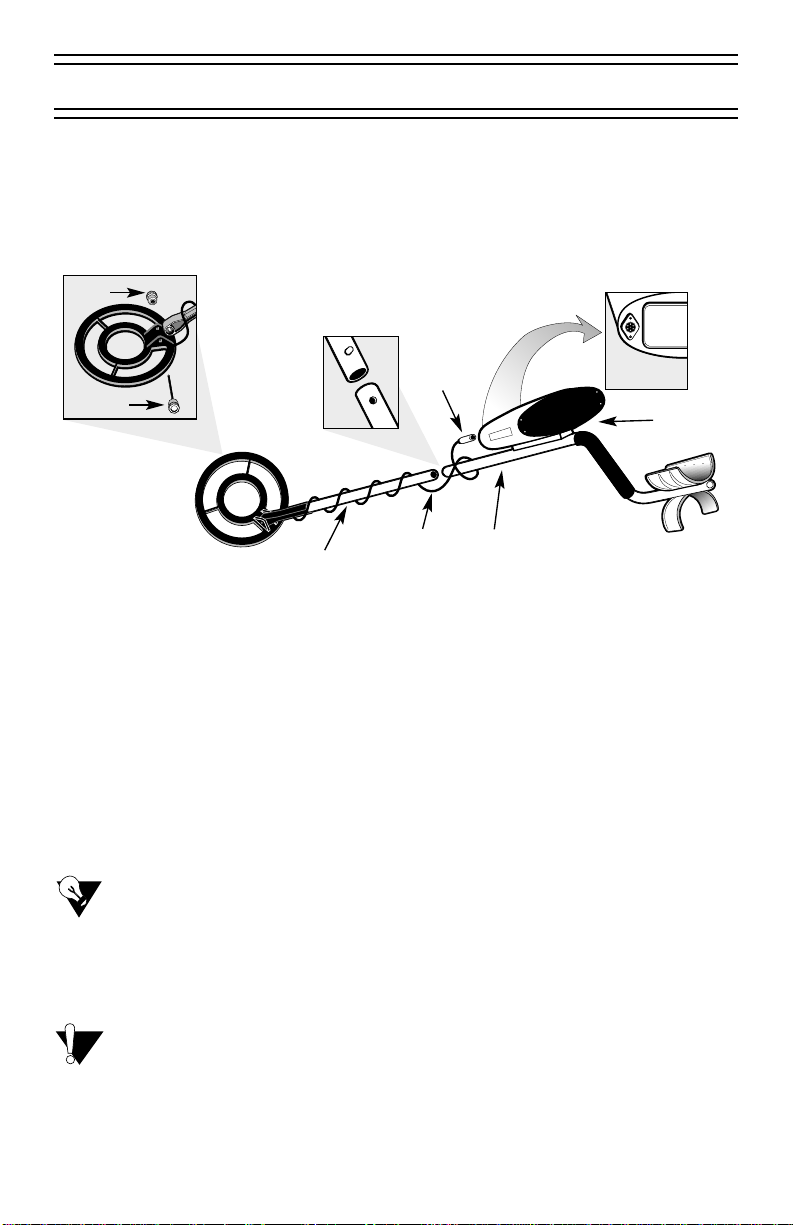
Assembly
Assembling your Land Ranger™ is easy and does not require any
tools. Using the following diagram as your guide, just follow these
easy steps.
▲To assemble the Land Ranger™
1. Attach the search coil to the lower stem with knob and bolt supplied.
2. Press the button on the upper end of the lower stem and slide the
lower stem into the upper stem.
3. With your ar m relaxed at your side and the search coil level to and
about one inch above the ground, adjust the stem to a length that lets
you maintain a comfortable upright posture.
4. Wind the search coil cable around the stem, leaving enough slack in
the cable to let you adjust the coil when you are hunting on uneven
ground.
TIP:
To adjust the coil, simply loosen the knob.
5. Insert the coil’s plug into the matching connector on the control
housing, making sure that the holes and pins line up correctly.
CAUTION:
Do not force the plug or you might damage it.
To disconnect the cable, pull out the plug—do not pull on the
cable.
3
Bolt
Knurled
Knob
Search
Coil
Cable
Upper
Stem
Control
Housing
Plug
Lower
Stem
Lower
Stem
Upper
Stem
Connector
on back of
control housing
4
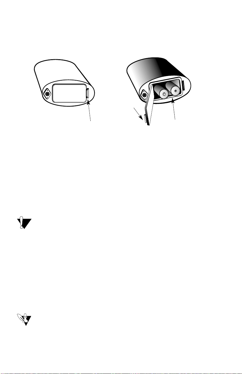
Batteries
Your Land Ranger™ metal detector requires two C ALKALINE batteries.
Using the following diagram as your guide, follow these easy steps to
install the batteries.
▲To install the batteries
1. To remove the battery compartment cover, carefully press the release
clip to the right of the cover.
2. Pull out the battery holder and install two C batteries.
3. Slide the battery holder back into the battery compartment.
4. To replace the cover, carefully insert the side opposite the release clip
first and then carefully press down on the other side until the cover
snaps in place.
CAUTION:
Use only fresh batteries of the required size and type. Batteries
must be ALKALINE type, such as Energizer C size LR14.
▲To check the batteries
1. Turn the unit ON.
The low battery indicator and all other arrow indicators appear
briefly in the LCD display, indicating that the detector is working
properly and the batteries are good.
2. If the arrow on the BATT (battery) dial points to R (Replace), replace
the batteries.
NOTE:
Many metal detector problems are caused by weak, dead, or
improperly connected batteries. If the detector does not turn on,
or if it shows signs of weak volume, improper tuning, erratic
operation, or drifting, replace the batteries.
Release
Clip
Release Clip of
Battery Door
C Size Alkaline
Batteries
TIP:
You can extend battery life by using headphones. The Land
Ranger™ is equipped with a headphone jack for use with any
1/4” stereo-type headset.
Turn the unit OFF when not in use, and if you do not plan to use
the detector for a week or more, remove the batteries.
For optimum performance, r eplace the batteries when the BATT
indicator on the LCD display indicates L (Low).
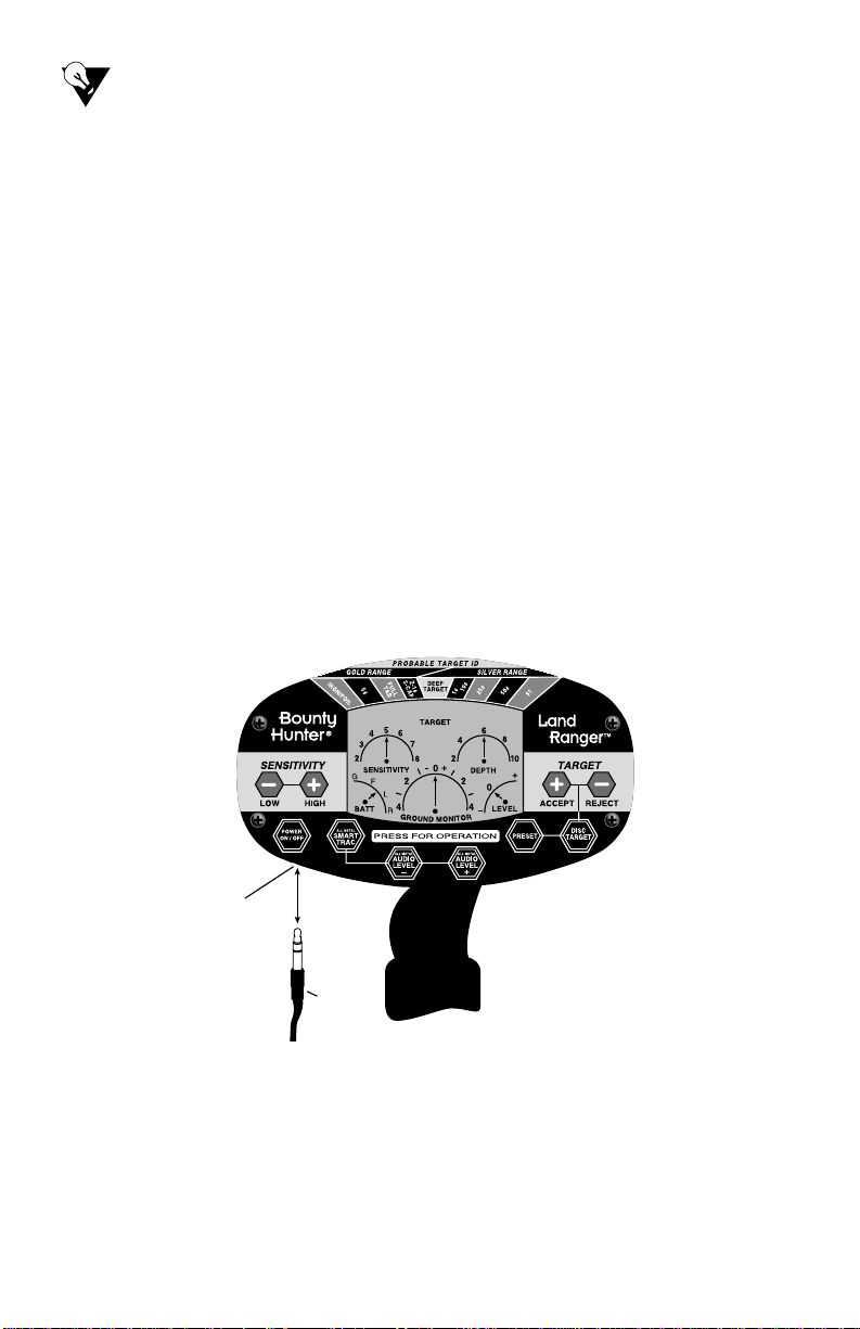
Headphones
The Land Ranger™ is equipped with a stereo headphone jack. Using
headphones (not supplied) with your metal detector not only extends
battery life, but also makes it easier to identify subtle changes in the
threshold levels for better detection results.
▲To connect and use headphones
1. Insert the headphone 1/4” plug into the headphone jack on the
underside of the control panel, as shown in the following diagram.
2. Set the headphone volume to the lowest setting before you begin
listening; after you begin listening, adjust each volume control to
a comfortable level.
5
Headphone
Jack
1/4 inch
Headphone
Plug

6
Listening Safety
• Do not listen at extremely high volume levels—extended high-volume
listening can lead to permanent hearing loss.
• Once you set the volume controls, do not increase them. Over time,
your ears adapt to the set volume level, so a volume level that may not
necessarily cause discomfort might still damage your hearing.
Traffic Safety
Do not wear headphones while operating your detector in traffic areas.
This practice could create a traffic hazard and is illegal in some areas.
While your headphones are designed to let you hear some outside
sounds at normal volume levels, they still present a traf fic hazard.
7
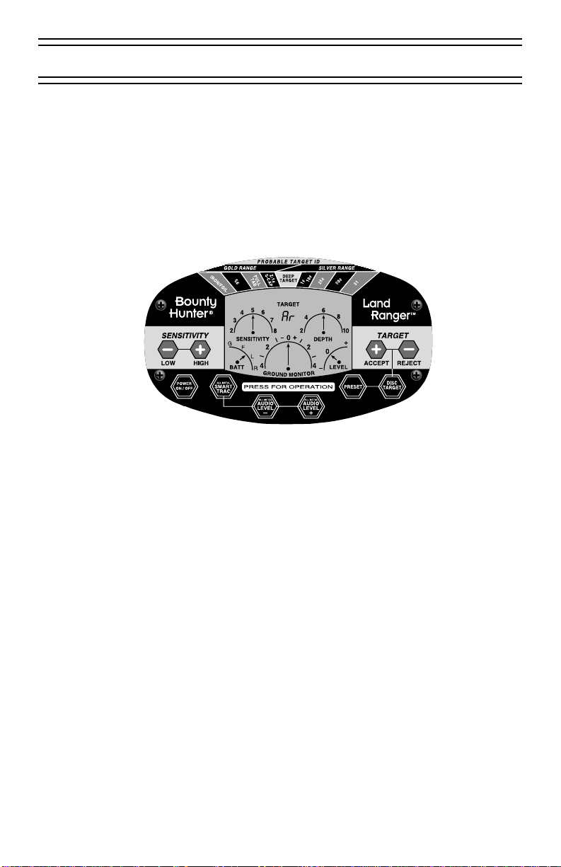
The control panel, as shown in the following diagram, is located at the
center of the control housing. It consists of an LCD display, probable
target ID fields, and several touch pads. The control panel provides
control and constant reference during all detector operations.
Combined with its 3-Tone Audio Target Identification, the Land
Ranger’s control panel provides as accurate a reference as possible
while detecting in the field.
Probable Target ID fields
The Probable Target ID fields, located at the top of the control panel,
represent various coin and metal types as well as a GOLD RANGE and
SILVER RANGE. The coin types can also signal other types of metals or
objects that are within a similar detection range. When the Land
Ranger™ senses a target, an arrow on the LCD display points to the
probable target on the Probable Target ID fields. Until the unit detects
another object, the arrow remains pointing to the most recently detected
object type. The following table lists the probable target IDs along with a
brief description of each.
Control Panel

8
PROBABLE TARGET ID Fields
Probable Target
ID
GOLD RANGE
SILVER RANGE
IRON / FOIL
Indicates that the target is probably iron or foil. Land Ranger™
has four levels of progressive iron discrimination—from small
to large. Some rusted oxidized iron may occasionally register in
the SILVER RANGE.
5¢
Located on the top portion of the control panel. The GOLD
RANGE is located on the left and the SILVER RANGE is on
the right. Other metal types can appear in this range: for
example, iron, foil and nickel appear under GOLD RANGE
and copper pennies appear under SILVER RANGE.
Description
Indicates that the target is possibly a nickel. Many gold rings
register as 5¢. A percentage of foil and many newer pull-tabs
are still detected as nickels.
Indicates that the object is probably a pull-tab. Some small
gold may also register as a pull tab.
Indicates that the target is probably a zinc penny (post 1982) or
a screw cap. This target ID is usually accompanied by a
medium tone. Other targets, such as large gold, may also
register in this field.
Indicates that the target is out of identification range.
These four fields indicate a coin type or an object or metal
within similar detection range. Many other objects are
identified in this range: for example, copper, brass and
oxidized metals such as cans, jewelry, tokens, medals, or
even junk metal objects that fall in the same range.
PULL TAB
Z-1¢
S-CAP
DEEP TARGET
1¢
10¢
25¢
50¢
$1
9
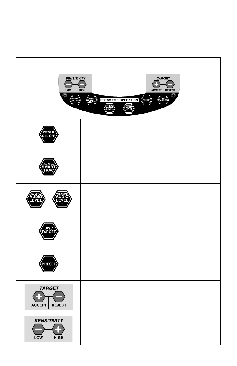
Dectector Touch pads
POWER ON/OFF is used to turn the detector on.
ALL METAL SMART TRAC is used to select the ALL
METAL mode of operation.
ALL METAL AUDIO LEVEL - and ALL METAL
AUDIO LEVEL + are used to adjust the detector’s
audio threshold in ALL METAL mode.
DISC TARGET is used to select DISCRIMINATION
mode and to “lock in” programmed settings.
PRESET is used to select preset targets in
DISCRIMINATION mode.
ACCEPT and REJECT are used to select customized
or PRESET targets in DISCRIMINATION mode.
LOW and HIGH are used to adjust the detector’s
sensitivity in DISCRIMINATION mode.
Touch pads
The detector control panel includes several touch pads as shown
and described in the following table. These touch pads are used to
set detector operation.

10
TARGET Readout
TARGET Meaning Description
Ar Air Value Indicates the detector is testing the air.
rY Discriminate Mode Indicates the detector is ready for operation
in ALL METAL mode.
gb Ground
Balance
Indicates the unit has taken ground
measurements and averaged them.
288 ID Numbers
0-299
Indicate air and ground measurements
and target value range for more detailed
target identification.
IR Discrimination Indicates the detector is ready for selective
target discrimination adjustment in the
DISCRIMINATION mode.
IR 1 Iron Mass Level 1 Indicates rejection of small iron objects.
IR 2 Iron Mass Level 2 Indicates rejection of small to medium
iron objects.
IR 3 Iron Mass Level 3 Indicates rejection of medium to large
iron objects.
Fo Foil Indicates object is composed of aluminum foil.
IR 4 Iron Mass Level 4 Indicates rejection of all iron objects.
LCD Display
The LCD display consists of the TARGET readout and both adjustment
and indicator dials. Arrows also appear at the top of the LCD display,
pointing to the probable target detected in the Probable Target ID fields.
▲TARGET Readout
The TARGET readout displays general detector operating information. It
appears in the top center of the LCD display between the SENSITIVITY
and DEPTH dials. The following table lists the general operating
abbreviations that appear under TARGET, their meaning, and a brief
description of each.
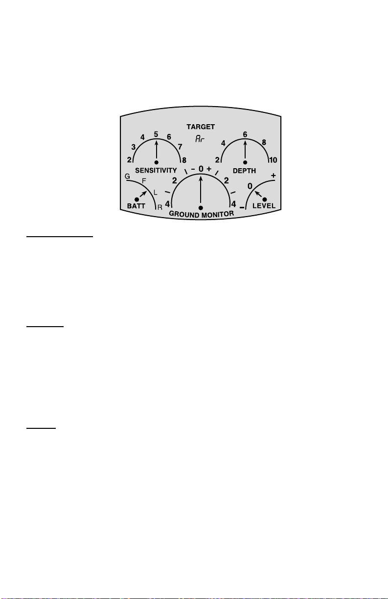
SENSITIVITY
The SENSITIVITY dial is located on the top left of the LCD display and is
used in conjunction with the LOW (-) or HIGH (+) touch pads to adjust
the Land Rangers™ sensitivity while operating in DISCRIMINA TION
mode. The arrow points to the selected setting. Adjust sensitivity to
eliminate electromagnetic interference or to adjust detector depth.
DEPTH
The DEPTH dial is located on the top right of the LCD display and
indicates the depth of the detected target in a range of 2-10 inches. The
arrow points to the detected depth. When the depth exceeds 10 inches,
an arrow appears under DEEP TARGET in the PROBABLE TARGET ID
fields. Depth detection is usually accurate to eight inches or less for
coin-sized objects only.
BATT
The BATT dial is located on the bottom left of the LCD display and
indicates battery strength as follows:
G=Good
F=Fair
L=Low
R=Replace
11
▲ Dials
The LCD display has five indicator/adjustment dials, as shown in the
following diagram. All are used to monitor the detector’s operation, and
the SENSITIVITY and LEVEL dials are used in conjunction with touch
pads on the control panel to adjust the detector’s sensitivity.

12
GROUND MONITOR
The GROUND MONITOR dial indicates whether the detector has
achieved ground balance in all soil conditions while operating in
ALL METAL mode.
LEVEL
The LEVEL dial, located on the bottom right of the LCD display, is
used in conjunction with the ALL METAL AUDIO LEVEL - or the
ALL METAL AUDIO LEVEL + touch pads to adjust the volume level
(threshold) when operating the detector in ALL METAL mode.
TARGET Readout
Value Range Objects
32-41
Nickel
$5 Gold Peice
Ring Pull-Tab
Beavertail Pull-Tab
Zinc Penny
Wheat Cent
Clad Dime
Mercury Dime
Clad Quarter
Silver Quarter
Clad Dollar
Franklin Half Dollar
Silver Dollar
Rusty Hinge
51-56
35-60
62-90
99-104
115-145
141-149
150-163
183-197
190-202
187-197
224-238
239-255
293-299
The table below list some common target value equivalents. With experience in
the field, you will recognize many types of metals by their numeric value.

13
Basic Operation
Turning the Detector ON
Follow these steps to turn on your Land Ranger™ detector.
1. Hold the detector with the search coil about waist high and press
the POWER ON/OFF touch pad.
The unit emits three beeps and Ar appears momentarily in the
TARGET readout, indicating that the detector is measuring the air.
2. When IR appears in the TARGET readout, lower the detector to the
ground and select from one of two Land Ranger‘ modes of operation:
◆ ALL METAL—This mode is used to detect all metals without motion.
In this mode, metals are identified by volume increases in only one
continuous medium tone.
◆ DISCRIMINATION—This is a motion mode that allows you to
eliminate undesirable objects from detection. In this mode, metals
are identified via the LCD display and with three distinct tones. By
pressing Disc Touch Pad after IR appears, you automatically enter
motion All Metal Mode; no metals are rejected.
DISCRIMINATION Mode
In DISCRIMINATION mode, you can accept all targets, select PRESET
targets, or program your own combination of targets to accept or reject.
In this mode, the detector must be in motion to detect targets.
▲To accept all targets
1. Perform the steps described in Turning the Detector ON section of
this manual.
2. Press the DISC TARGET touch pad to “lock-in” the programming.

14
The blinking arrow under IRON/FOIL disappears and IR
appears in the TARGET readout (indicating that the detector is
set to accept all metals, including all levels of iron) as shown
in the following diagram.
▲To select PRESET targets
The Land Ranger‘ has three PRESET modes:
1. Per form the steps described in Turning the Detector ON section of
this manual.
2. Press the DISC TARGET touch pad.
A blinking arrow appears under IRON/FOIL in the Probable
Target ID fields, meaning the detector is ready for programming.
3. Press the PRESET touch pad once to select PRESET 1.
The blinking arrow under IRON/FOIL is replaced by an R.
4. Press the PRESET touch pad twice to select PRESET 2.
An R appears under PULL TAB in the Probable Target ID fields.
5. Press the PRESET touch pad three times to select PRESET 3.
An R appears under Z-1¢/S-CAP in the Probable Target ID fields.
PRESET 1
Rejects all levels of iron and aluminum foil.
PRESET 2
Rejects pull-tabs, iron and all objects rejected in PRESET 1 mode.
PRESET 3
Rejects zinc pennies, screw-caps, pull-tabs, aluminum, other similar
objects, and all objects rejected in PRESET 1 and PRESET 2
modes.

15
R appears under the metals excluded by the PRESET
level you selected, as shown in the following example.
Example of Land
Ranger™ set to PRESET
2 (iron/foil and pull tabs
are rejected).
NOTE:
Pressing PRESET a fourth time clears all PRESET settings
and the unit resets to accept all metals.
▲To select customized targets
The Land Ranger™ has a valuable detection feature called Progressive Ir on
Discrimination which allows you to set four levels of iron discrimination
based on size. Before you can customize targets, you must first select
the size of iron to eliminate.
Progressive Iron Discrimination Levels
IR 1
IR 2
IR 4
IR 3
Rejects the smallest of iron objects, such as tacks, small screws and
nails, and BB size objects.
Rejects objects up to about twice the size of IR1 type objects.
Rejects mid-size objects such as a pocket knife, but detects larger
objects such as a pistol, cannonball or strongbox.
Rejects all iron objects.
1. Per for m the steps described in Tur ning the Detector ON section of
this manual.
2. Press REJECT once to select IR1.
IR1 appears in the TARGET readout.
3. Press REJECT twice to select IR2
IR2 appears in the TARGET readout.
R
R

16
4. Press REJECT three times to select IR3.
IR3 appears in the TARGET readout.
5. Press REJECT four times to select IR4.
IR4 appears in the TARGET readout.
6. Press ACCEPT after your selection to “lock-in” the iron discrimination
level.
The level of iron discrimination you selected appears in the
TARGET readout, an R appears under IRON/FOIL, and the
blinking arrow appears under 5¢ as shown in the following
example.
7. Press REJECT or ACCEPT, depending on whether you want to
accept or reject the 5¢ targets.
NOTE:
Normally, you want to accept the 5¢ targets because many
gold items are detected as such.
The blinking arrow appears under PULL TAB.
8. Depending on how you want to customize your targets, continue
pressing ACCEPT or REJECT as the blinking arrow appears in the
remaining Probable Target ID fields.
TIP:
To accept the remaining targets and “lock-in” your
selection(s), you can press DISC TARGET at any time.

17
The level of iron discrimination you selected appears in the
TARGET readout, and R appears under your customized
selections as shown in the following diagram.
Example of Land Ranger™ set for
IR 4 iron discrimination with
customized selections for pull tab,
screw cap and zinc penny rejection.
▲To adjust sensitivity in DISCRIMINATION mode
After you select your PRESET or customized targets, you can adjust the
detector’s sensitivity. The default setting is 5 on the SENSITIVITY dial.
Press the LOW (-) or HIGH (+) touch pad on the control panel to
adjust the detector’s sensitivity while monitoring your adjustment on
the SENSITIVITY dial.
The arrow on the SENSITIVITY dial in the LCD display points to the
selected setting.
▲To listen to tones in DISCRIMINATION mode
DISCRIMINATION mode includes the Audio Target Identification
(ATI) feature that identifies objects using three different tones or no
response at all, as shown in the following diagram.
NOTE:
Three-tone Audio Target Identification is disabled in the
ALL METAL mode.
NO
RESPONSE
Iron & Steel
LOW
TONE
Gold & Nickel
MEDIUM
TONE
Old & New
Pull Tabs
HIGH
TONE
Copper, Silver &
Bronze

18
Tips for listening in DISCRIMINATION mode
◆ Most iron and steel objects emit a low tone, but on occasion
when the iron is highly oxidized, you might hear a high tone. For
example, some rusted bottle caps will emit a high tone and
appear under the SILVER RANGE in the Probable Target ID
fields. You can prevent this from happening by selecting the size
of iron to eliminate. See To customize targets section of this
manual for instructions on how to set progressive iron
discrimination levels.
◆ All nickels and many gold items emit a low tone, but some larger
gold objects emit a medium tone, depending on purity. These
objects will appear in the GOLD RANGE in the Probable Target
ID fields, unless you’ve selected to reject this range.
◆ Old and new pull tabs usually emit a medium or low tone. A
Beaver Tail (pull tab broken in half) or a bent, folded or highly
oxidized pull tab may emit a low tone.
ALL METAL Mode
In the ALL METAL mode, the volume of one continuous medium tone
increases when the Land Ranger‘ detects metal. The detector does not
have to be in motion in this mode.
▲To select ALL METAL mode
1. Perform the steps described in Turning the Detector ON section of
this manual.
2. Press the ALL METAL SMART TRAC touch pad.
gb appears briefly in the T ARGET readout, followed by rY
indicating that the unit has measured the ground and is ready for
operation in ALL METAL mode), as shown in the following diagram.
Note that since targets cannot be
rejected in this mode, there are no
Rs under the probable ID types.
3. If rY does not appear in about 10 seconds, move the search coil
to another area.

19
TIP:
Initially, if the unit is not reacting properly, push the ALL
METAL SMART TRAC touch pad a couple of times to make
sure that the batteries are connected and not discharged.
▲To adjust sensitivity in ALL METAL mode
For maximum sensitivity, you should hear a slight threshold hum while
operating in ALL METAL mode. If you do not hear this threshold hum,
sensitivity is low and the audio level requires adjustment.
To adjust the audio level
1. Make sure that the arrow in the GROUND MONITOR dial points
to 0; sensitivity adjustments should only be made when the
GROUND MONITOR dial indicates that the detector is properly
ground balanced.
2. Press the ALL METAL AUDIO LEVEL - touch pad or the ALL
METAL AUDIO LEVEL + to adjust the audio level.
The arrow on the LEVEL dial in the LCD display reflects your
adjustment, +/- and you should hear a slight threshold hum.
▲To adjust detector when ground conditions change
If actual ground conditions change (example: moving from low to
highly mineralized ground, or vice versa) the SMART TRAC system
automatically makes the adjustment for the variation. You will hear
a momentary change in the threshold hum while the unit makes the
adjustment. Do not make any adjustments to the ALL METAL
AUDIO LEVEL at this time; simply wait about 10 seconds and the
hum will return to nor mal.
If the hum does not return to normal after 10 seconds
1. Press ALL METAL SMART TRAC for an instant ground balance
update.
2. If the hum does not return to nor mal after pressing ALL METAL
SMART TRAC, lower the unit’s threshold using the ALL METAL
AUDIO LEVEL +/- touch pads.
If you are getting a constant signal
1. Try moving the search coil to a dif ferent location and press ALL
METAL SMART TRAC for instant ground balancing (in case
metal is setting the unit off).
2. If you are still getting a constant signal, lower the unit’s threshold
using the ALL METAL AUDIO LEVEL +/- touch pads.

20
▲To update ground balancing
Anytime the detector detects a target, normal fluctuations in ground
conditions cause the arrow on the GROUND MONITOR dial to move
from its center 0 position slightly right or left; the Land Ranger™ SMART
TRAC feature automatically adjusts to these minor variances usually
within 15 to 20 seconds. If the arrow does not return to its center 0
position after 15 to 20 seconds, or if at any time you are unsure about
the ground balance, do the following:
1. First, make sure that you are not standing over a detected target.
2. Press the ALL METAL SMART TRAC touch pad until gb appears
in the TARGET readout.
3. When rY appears in the TARGET readout, the unit is ready for
use.
TIP:
When ground balancing the unit, make sure that there is no metal
on top of or under the ground, otherwise you won’t be able to tell if
the tone being emitted is caused by metal or soil mineralization. If
you think you are over metal, move to another spot—observe your
GROUND MONITOR carefully when moving the search coil to
another spot. If in the - range, it is balancing for negative conditions;
if in the + range, it is balancing for positive ground conditions or
detecting a metal object.
NOTE:
Once you’ve adjusted for ground conditions, your settings will
not change until you turn the unit OFF , even if you go back and
forth between ALL METAL mode and DISCRIMINATION mode.

21
Testing the detector
Test your detector using different coin types (penny, nickel, etc.) and
other miscellaneous metal objects such as a nail, a gold ring, a railroad
spike, etc. Always test the detector away from other metals not selected
for testing.
▲Ground Testing
Do not test the unit indoors on the floor because floors usually contain
metal that may interfere with the detector’s signal or even mask the
signal completely.
◆ In DISCRIMINATION or PRESET mode, you must move the
search coil over the object—do not move the coil too quickly over
the object and keep the coil 1/2” above the ground when
sweeping.
◆ In ALL METAL mode, movement of the search coil is not
required—hold the coil over the object and 1/2” above the
ground.
▲Air Testing
Follow these steps to test your detector as it lays stationary and you
pass objects over its search coil, as illustrated in the following diagram.
Position of detector and
object when air testing the
Land Ranger™
1. Place the detector on a table and rotate the search coil towards
the ceiling.
2. Remove any watches and rings from your hands and make sure
no metal in or on the table is close by.
3. If your are in DISCRIMINATION or PRESET mode, sweep one of
the objects you selected for testing across (and about 4” from) the
coil.

22
4. If you are in ALL METAL mode, hold one of the objectsyou selected
for testing over (and about 4” from) the coil.
5. Since gravity causes coins to lie flat on or under the ground, sweep
coins with the flat surface parallel to the search coil. Bounty Hunter™
models with LCD indicators are programmed to sense the coin type
and depth while looking at the flat side of the coin; sweeping the edge
of the coin across the search coil may cause inaccurate readings.
6. If the detector is not properly identifying the object, try sweeping/
holding the object closer to the coil and make sure that you are
sweeping the flat surface of the object parallel to the search coil.

23
Using the Detector in the Field
▲Coil Movement
◆ When sweeping the coil, be careful to keep it level with the
ground about 1/2” from the surface—never swing the coil
like a pendulum The following diagrams illustrate incorrect
and correct coil movement.
Right
Do not swing the coil like a pendulum.
Swing the coil level with the ground.
Swing the coil in a half-circle and repeat this
motion every step you take to guarantee
complete coverage of the area.
Swing the search coil gently side-to-side, slightly
overlapping each seep as you move forward.
Wrong

24
◆ Make sure you keep your search coil consistently about 1/2”
above the ground as you sweep. Raising the coil during the
sweep or at the end of the sweep will cause false readings.
◆ Move slowly—hurried movement will only cause you to miss
targets.
▲Pinpointing the target
Accurate pinpointing takes practice. Follow these steps for best
results when attempting to pinpoint a target.
1. When you hear a good tone response indicating a buried target,
continue sweeping the search coil over the target in a narrowing
side-to-side pattern.
2. Keeping your eyes on the ground, notice where the “beep” occurs
as you move the search coil slowly side-to-side.
3. Stop the search coil directly over this spot.
4. Move the search coil straight forward and straight back towards
you a couple of times.
5. Again, keeping your eyes on the ground, notice where the “beep”
occurs.
6. If necessary, “X” the target at different angles to zero in on the
exact spot on the ground where the “beep” occurs. The following
diagram illustrates the proper “X-ing” technique.
TIP:
If “X-ing” the target does not yield one point, try finding the
perimeter of the object by “circling” the object; using the
leading edge of the search coil, circle around the large object.
Many large objects will seem irregular in size.
Try drawing an X over the
location where the tone is
being emitted.

25
▲False signals and chatter
The biggest frustrations you will encounter when using a metal detector
are false signals and chatter. The Land Ranger™ is a very sensitive,
deep-seeking detector. It will respond loudly to many targets for which
other detectors might only emit a weak signal. As a result, the detector
may emit false, trash-induced signals that seem confusing. Electrical
interference, or large, irregular trash objects can also cause false
signaling. With practice using your Land Ranger‘ in the field, you will
learn to recognize the broken, non-repeatable tones that characterize
the false signal.
Tips for dealing with false signaling
◆ Dig only those targets that emit a strong, repeatable signal as
you move the search coil over the same spot on the ground. Most
good objects will respond with a consistent, repeatable signal. If a
signal does not repeat after sweeping the coil directly over the
suspected target a few times, it is more than likely trash metal.
◆ Metal Detectors emit magnetic fields which can interfere with one
another. If you are detecting with another person who has a
detector, you could have interference between the detectors;
always keep two detectors at least 20 feet apart. Also, avoid
searching under electrical power lines.
◆ As you sweep the search coil back and forth over the ground,
learn to recognize the dif ference between the signals that occur at
random and signals that are stable and repeatable.
◆ When searching very trashy ground, it is best to scan small areas
with slow, short, overlapping sweeps.
◆ To prevent erratic signals and difficult pinpointing in trashy
areas, set your detector to rejects all trash metals (i.e., reject all
metals in the GOLD RANGE) or consider purchasing the Bounty
Hunter™ 4” Gold Nugget Coil System.
Chatter
Electromagnet fields occur naturally or can be man-made. Indoors,
household appliances, particularly TVs and lights, emit electromagnetic
energy. Outdoors, power lines, either overhead or buried, create
significant interference and the earth also emits electromagnetic
energy. The detector’s coil creates a magnetic field. The detector
senses other electromagnetic fields and can sometimes chatter or
beep erratically. If this happens, reduce the detector’s sensitivity.

26
▲Ground Balancing
To achieve proper ground balancing in motion modes, the search coil must
stay in motion at a constant speed. Speeding up or slowing down the coil
rhythm causes the detector to calculate a false “average mineralization.” The
most challenging environments are beaches and black sand deposits where
gold is commonly found. The water line that separates wet sand from dry
sand is an abrupt change in soil condition which can confuse even a Bounty
Hunter™. If you are searching a beach, keep the detector on either wet or dry
sand—moving between the two can induce false signaling. Black sand is very
highly mineralized, and without an advanced technology detector, finding a
gold nugget is like looking for a needle in a haystack. Gold prospecting is
possible with all Bounty Hunter™ detectors, but for best results, use the Land
Star™, Land Ranger™, or Timer Ranger™.
▲Resetting the detector
If battery voltage is low or if you are testing with the search coil near a
large metal object, the detector might “lock up” and sound a continuous
tone. To reset the detector, do one (or all, if necessary) of the following:
1. Reset the detector by turning it OFF and ON repeatedly.
2. Move to a different testing location.
3. Check and replace the batteries, if necessary.

27
Detector Applications
Coinshooting
Coinshooting is probably the most popular metal detecting application.
Coinshooting opportunities abound—even your own yard may yield some
interesting old coins. You can search for coins just about anywhere—parks,
baseball fields, yards, dirt parking lots and swimming areas are only a few
of the many possibilities.
Most coinshooters strive, at the very least, to find silver coins (pre-1955). You can use
clad coins in current circulation to practice and test your detector’s abilities to identify
targets.
▲Recommended Mode of Operation
The type of area where you are hunting and the level of trash in that area
usually determines the mode of operation. The recommended mode of
operation for coinshooting is DISCRIMINATION mode with the following
settings.
PRESET Level 3 (P3)
If an area is heavily trash laden, try using the third level of PRESET
(PRESET 3). See the DISCRIMINATION Mode, To select PRESET targets
section of this manual for instructions on how to select PRESET levels.
In this mode, the unit responds to all coins types and other possible
trash metal that falls under these coin types. This mode may not,
however, detect some gold rings, and might still detect a percentage of
pull tabs especially those that are broken in half (Beaver Tails).
As you are sweeping your coil, you may get many types of signals and
idications in a trashy area. Try to dig only signals that are repeatable and lock
onto the target ID. Depending on what level of SENSITIVITY you’ve selected,
you may encounter numerous DEEP TARGET indications. Only attempt to
dig a DEEP TARGET indication if it is repeatable. Even then, the signal may
disappear once you start digging, possibly because the object is highly
oxidized or is recognized as trash metal once the detector comes into range.

28
Customized target selection to reject all trash metals
DISCRIMINATION mode allows you to further narrow your
discrimination if you are encountering many Nickel indications that
turn out to be pull-tabs or foil—a common problem in heavily
trashed areas. Some Beaver Tails (pull-tabs broken in half) have the
same detection properties as nickels.
Customize your selections so that you eliminate all metal that falls
in the GOLD RANGE. See the DISCRIMINATION Mode, To customize
targets section of this manual for instructions on how to customize
targets. Eliminating all metals in the GOLD RANGE narrows your
discrimination to strictly silver and copper coins and other metals
that may fall in the SILVER RANGE.
Your LCD display will appear as shown in the following diagram.
TIP:
Once you’ve had some practice using your Land Ranger™
detector, you may want to fine-tune it so that it will not
eliminate zinc pennies or nickels. Sometimes, Indian Head
pennies indicate as zinc pennies and gold coins may indicate
as nickels.
The Land Ranger™ is set to reject all objects
in the GOLD RANGE, thus minimizing trash
and detecting mostrly silver and copper
coins.
R
R
R
R

29
Relic Hunting
A relic is anything of historical value, especially reflecting another age.
Before you undertake a search for relics, first do some research in your
local library or on the Internet. Look up old newspapers and find out
more about your community’s history. Discover what historical events
may have taken place in your locality and where historical landmarks are
hidden from present day progress. Many times there are new buildings
and pavement over where historical events took place or where historical
landmarks once stood. Try to pinpoint these locations on a map.
Hopefully, you will find an empty lot or a farmer’s field where a historical
landmark was once located. Remember, have respect for private property
and get the owner’s permission before searching for relics on private land.
▲Recommended mode of operation
When relic hunting, you will want to detect iron along with precious
metals. The recommended mode of operation for relic hunting is
DISCRIMINATION or ALL METAL mode with the following settings.
ALL METAL mode
When relic hunting in the ALL METAL mode, be careful to swing the
search coil slowly, listening for fluctuations in volume. When you
encounter a louder signal, experiment by sweeping around the area
to determine where the signal starts and stops. This is not only
helpful in determining if the signal is truly a target, but in
pinpointing its exact location and size. If you cannot isolate the
target due to concentrations of targets, try de-tuning the detector by
Relics are time capsules of
history since every relic has a
story to tell. More that
monetary value, relics have
historical value. While there are
instances where collectors have
paid substantially for a relic,
they are of much more value to
the local museum where the
community’s history is revered.

30
pressing the ALL METAL AUDIO LEVEL (-) touch pad. This will
lower the sensitivity and narrow the detection field, thus minimizing
detection of metal objects surrounding the desired target.
DISCRIMINATION mode
If you are relic hunting in DISCRIMINATION mode, you want the unit to
detect all types of metal, including iron objects. Set the detector to accept
all metals. See the DISCRIMINATION Mode, To accept all metals section of
this manual for instructions on how to set the detector to accept all
metals. If your are encountering a lot of nails, set the iron discrimination
level to IR 2 or IR 3.

31
Jewelry Hunting
When targeting jewelry items, consider where these items are commonly
lost. There are many possibilities, including playing fields where a variety
of sports take place, beach areas, playgrounds, and sandboxes.
▲Recommended mode of operation
Since the main objective when jewelry hunting is to detect all gold
items, the recommended mode of operation is DISCRIMINATION
mode with the following settings.
PRESET Level 3 (P3)
Try using the third level of PRESET (PRESET 3). See the DISCRIMINATION
Mode, To select PRESET targets section of this manual for instructions on
how to select PRESET levels. The third level of PRESET eliminates most
trash items while detecting most all coin types and other possible gold and
silver items similar to the coin types (such as jewelry). Fortunately, most
small gold items fall under the 5¢ indication. Also, make sure that you
accept all 4 levels of iron, since small gold rings may fall in the IRON/FOIL
range. While you will dig up a lot of trash in this setting, you are
guaranteed that no gold items are escaping detection.
Customized target selection
You may also want to customize your selection of targets, depending
on what type of trash you are encountering. For example, if you’re
encountering many pull tabs but very little iron, try eliminating pull
tabs only. See DISCRIMINATION Mode, To customize targets section
of this manual for instructions on how to customize your targets.
When jewelry hunting, it is not uncommon to find
many coins in the process of digging up rings.

32
Gold Prospecting
Using a metal detector to retrieve gold is still a relatively new art form.
Gold prospecting poses totally different challenges than coinshooting or
jewelry hunting. The biggest challenge is the black sand (highly
mineralized soil with iron content) where gold is typically found; this
highly mineralized soil may set off your detector, producing false signals.
The Land Ranger’s SMART TRAC system constantly measures ground
conditions and makes adjustments for highly mineralized areas, making
it well-suited for gold prospecting.
Metal detectors have been instrumental in creating
another gold rush in the last two decades. Older gold
mines that had long been closed have been reopened with
metal detectors used as the main tool for gold retrieval.
Today, metal detectors are used in every aspect of gold
detecting—from searching out the mother lode to finding
“placer” deposits, metal detectors have proven
indispensable.
▲Recommended mode of operation
The recommended mode of operation for gold prospecting is ALL
METAL mode. This mode ensures the detection of smaller objects,
such as gold nuggets. Gold flakes are difficult to detect unless they
are highly concentrated. See the ALL METAL mode section of this
manual for instructions on its operation.
▲T ips for gold prospecting
◆ Sweep the search coil and listen carefully for volume fluctuations.
◆ The unit emits a continuous louder tone when it detects precious
metals and the search coil is over the target. Try moving the coil
on the outside of the signal to determine the object’s size and
exact location.
◆ Remember that highly mineralized soil where gold is found can
cause false readings

33
Cache Hunting
A cache is anything of value that may be hidden or buried to prevent
theft. Long ago, people would hide their life savings near their homestead
because they did not trust banks. Caches also refer to pillaged or lost
treasure.
Cache hunting requires extensive research and careful
deduction.
▲Recommended mode of operation
Since caches are usually buried deep, the recommended mode of
operation for cache hunting is ALL METAL mode. This mode does
not require motion, helping you determine the size of the object and
pinpoint its location. While hunting in this mode might yield
considerable trash targets, it may be worthwhile if there is strong
evidence that the particular cache you’re hunting for actually exists.
See the ALL METAL mode section of this manual for instructions on
its operation.
▲T ips for cache hunting
◆ Sweep the search coil slowly; pay particular attention toany
increase in volume, indicating that the unit has detected metal.
◆ T ry clearing all sur face trash metal to allow the Land Ranger™
to detect deeper targets without interference. You may need to
adjust the detector’s sensitivity; see To adjust sensitivity in ALL
METAL mode section of this manual for instructions on
adjusting the detector’s sensitivity.
◆ If the unit emits a continuous loud signal, there may be too
much trash in the area for it to operate at its ground balance
peak. Try de-tuning the detector by pressing the ALL METAL
AUDIO LEVEL (-) touch pad so that you can distinguish
smaller metal.
◆ If adjusting sensitivity does not work, find another area close
by that contains less metal to assure that the unit is properly
ground balancing.

34
Troubleshooting
Common Problems
The following table lists common problems that you may encounter
when using your metal detector.
Problem Probable Cause(s) Solution(s)
Detector is emitting
false signals in the
field.
• SENSITIVITY may be set
too high.
• Improper coil
movement.
• Highly oxidized metal.
• Reduce SENSITIVITY per
instructions in this manual
for your mode of operation.
• Swing the coil slowly.
• Abandon the target—if the
signal does not repeat as
you sweep the same area,
the target is usually highly
oxidized (rusted) metal and
not worthwhile.
• LCD readout is not
“locking in” or
identifying while
passing over a
target.
• Detector emits more
than one tone over
the same target.
• More than one object
over the area you are
sweeping.
• Odd, unrecognizable
metal.
• Highly oxidized metal.
• SENSITIVITY may be set
too high.
• Use 4” coil accessory to
narrow detection field.
• Sweep over target at
different angles.
• Abandon the target—if the
signal does not repeat as
you sweep the same area,
the target is usually highly
oxidized (rusted) metal and
not worthwhile.
• Reduce SENSITIVITY per
instructions in this manual
for your mode of operation.
Detector not stable
and has a pulsing,
distorted tone instead
of a clear one.
• Operating very near
another detector.
• Operating near power
lines that can interfere
with detector’s
frequency.
• Move at least 20 feet from
the second detector.
• Move away from power
lines.

35
Problem Probable Cause(s) Solution(s)
Detector is repeating
a loud tone or
constant, repeating
tones (locking up).
• Batteries are low.
• Coil or coil connection
is damaged.
• Replace batteries per
instructions in this manual.
• Reset the detector per
instructions in this manual.
• Replace coil.
• Check coil plug connection.

36
Caring for Your Metal Detector
Your Land Ranger™ Metal detector is an example of superior design
and craftsmanship. The following suggestions will help you care for
your metal detector so that you can enjoy it for years.
◆ Handle the metal detector gently and carefully. Dr opping it can
damage circuit boards and cases and can cause the metal
detector to work improperly.
◆ Use and store the metal detector only in nor mal temperature
environments. Temperature extremes can shorten the life of
electronic devices and distort or melt plastic parts.
◆ Wipe the metal detector with a wet cloth occasionally to keep it
looking new. Do not use harsh chemical, cleaning solvents, or
strong detergents to clean the metal detector.
◆ The search coil is waterpr oof and can be submerged in either
fresh or salt water. Be careful to prevent water entering the
chassis. After using the coil in salt water, rinse it with fresh
water to prevent corrosion of the metal parts.
CAUTION:
Modifying or tampering with the detector’s internal components
can cause a malfunction and will invalidate your detector’s
warranty.

I-1
Symbols
$1 8
Numerics
1¢ 8
25¢ 8
288 10
5 8
5¢ 8
50¢ 8
A
ACCEPT 9
adjusting
for change in ground conditions 19
sensitivity in ALL METAL mode 19
sensitivity in DISCRIMINATION mode 17
air testing 21
ALL METAL AUDIO LEVEL - 9
ALL METAL AUDIO LEVEL + 9
ALL METAL mode 18
adjust detector when ground conditions
change 19
adjust sensitivity in 19
selecting 18
update ground balancing 20
ALL METAL SMART TRAC 9
all targets
accepting 13
Ar 10
assembly 3
audio target identification 17
B
basic operation 13
turning the detector on 13
basics of metal detecting 1
detection 2
discrimination 1
ground balancing 2
metal types 1
BATT dial 11
batteries 4
checking 4
installing 4
C
cache hunting 33
recommended mode of operation 33
tips 33
caring for you metal detector 36
chatter 25
in the field 25
coil movement 23
coinshooting 27
recommended mode of operation 27
common problems, troubleshooting 34
control panel 7
LCD display 10
probable target ID fields 7
touch pads 9
customized targets 15
selecting 15
D
DEEP TARGET 8
depth detection, definition of 2
DEPTH dial 11
detector
applications 27
caring for 36
resetting 26
testing 21
using in the field 23
detector applications 27
cache hunting 33
coinshooting 27
gold prospecting 32
jewelry hunting 31
relic hunting 29
dials 11
BATT 11
DEPTH 11
GROUND MONITOR 12
LEVEL 12
SENSITIVITY 11
DISC TARGET 9
DISC TARGET mode settings
accept all targets 13
DISCRIMINATION mode 13
accept all targets 13
adjust sensitivity in 17
select customized targets 15
select PRESET targets 14
discrimination, definition of 1
DISCRIMINIATION mode
listen to tones in 17
F
false signals 25
in the field 25
tips for dealing with 25
Fo 10
G
gb 10

I-2
getting started 3
assembly 3
batteries 4
headphones 5
gold prospecting 32
recommended mode of operation 32
tips 32
GOLD RANGE 8
ground balancing
definition of 2
in the field 26
updating 20
when ground conditions change 19
GROUND MONITOR dial 12
ground testing 21
H
headphones 5
connecting and using 5
listening safety 6
traffic safety 6
HIGH 9
I
IR 10
IR 1 10, 15
IR 2 10, 15
IR 3 10, 15
IR 4 10, 15
iron discrimination level
IR1 15
IR2 15
IR3 15
IR4 15
iron discrimination levels, description of 15
IRON/FOIL 8
J
jewelry hunting 31
recommended mode of operation 31
L
LCD display 10
dials 11
TARGET readout 10
LEVEL dial 12
listening
to tones in DISCRIMINATION mode 17, 18
LOW 9
M
metal types 1
aluminum 1
copper 1
gold 1
iron 1
silver 1
zinc 1
mode of operation
ALL METAL 13, 18
DISCRIMINATION 13
P
pinpointing the target 24
POWER ON/OFF 9
PRESET 9
PRESET 1 14
PRESET 2 14
PRESET 3 14
PRESET targets 14
selecting 14
probable target ID
$1 8
1¢ 8
10¢ 8
25¢ 8
5¢ 8
50¢ 8
DEEP TARGET 8
GOLD RANGE 8
IRON/FOIL 8
PULL TAB 8
S-CAP 8
SILVER RANGE 8
Z-1¢ 8
probable target ID fields 7
descriptions of 8
PULL TAB 8
R
REJECT 9
relic hunting 29
recommended mode of operation 29
reset
detector 26
ground balance 19
ground balancing 20
resetting the detector 26
rY 10
S
S-CAP 8
selecting
ALL METAL mode 18
all targets 13
customized targets 15
PRESET targets 14

I-3
sensitivity
adjusting in ALL METAL mode 19
adjusting in DISCRIMINATION mode 17
SENSITIVITY dial 11
silver range 8
T
TARGET readout 10
descriptions of 10
values 12
testing the detector 21
air testing 21
ground testing 21
touchpads
descriptions of 9
troubleshooting 34
common problems 34
turning detector on 13
U
using the detector in the field 23
chatter 25
coil movement 23
false signals 25
ground balancing 26
pinpointing the target 24
Z
Z-1¢ 8

I-4
NOTES

NOTES

NOTES

NOTES

NOTES

Treasure Hunter’s Code of Ethics
◆ Respect the rights and property of others.
◆ Observe all laws, whether national, state or local.
◆ Never destroy historical or archaeological treasures.
◆ Leave the land and vegetation as it was. Fill in the holes.
◆ All treasure hunters may be judged by the example you set.
Always obtain permission before searching any site. Be
extremely careful with your probing, picking up and discarding
of trash, and ALWAYS COVER YOUR HOLES.
First Texas Products
Limited 5 year Warranty
Bounty Hunter™ metal detectors are warranted against defects
in workmanship or materials under normal use for five years
from date of purchase to the original user. Liability in all events
is limited to the purchase price paid. Liability under this
Warranty is limited to replacing or repairing, at our option, any
Bounty Hunter™ detector returned, shipping costs pre-paid, to
First Texas Products. Damage due to neglect, accidental damage
or misuse of this product is not covered by this Warranty.
Copyright© 2002 by First Texas Products, L.P.
All rights reserved, including the rights to reproduce this book or parts
thereof, in any form, except for the inclusion of brief quotations in a review.
Published by First Texas Products, L.P.
Bounty Hunter™ is a registered trademark of First Texas Products, L.P.
www.detecting.com
First Texas Product, L.P.
1100 Pendale
El Paso, TX 79907
 Loading...