

Boston Scientific Bionic Navigator 3d NM-7153-11A, Bionic Navigator 3d NM-7153-11AR, Bionic Navigator 3d NM-7153-30, Bionic Navigator 3d NM-7153-30R System Programming Manual
Page 1

Programming Manual
en fr de nl
Bionic Navigator™ 3D
System Programming
Manual
Manuel de programmation
Programmierhandbuch
Programmeerhandleiding
90930923-31 REV A
Page 2

Bionic Navigator™ 3D Programming Manual
en
Guarantees
Boston Scientic Corporation reserves the right to modify, without prior notice, information
relating to its products in order to improve their reliability or operating capacity.
Trademarks
All trademarks are the property of their respective holders.
Additional Information
For Indications and related information, see the Indications DFU. For contraindications,
warnings, precautions, adverse events summary, physician instructions, component disposal,
and contact information for Boston Scientic, refer to the Information for Prescribers DFU for
your spinal cord stimulator system. For other device-specic information not included in this
manual, labeling symbols, and warranty information, refer to the appropriate DFU as listed on
your Reference Guide.
Product Model Numbers
Model Number Description
NM-7153-11A Clinician Programmer
NM-7153-11AR Clinician Programmer (Refurbished)
NM-7153-30* Clinician Programmer
NM-7153-30R* Clinician Programmer (Refurbished)
*Applicable after installation of 9028372-110 software.
Bionic Navigator™ 3D Programming Manual
90930923-31 REV A ii of iv
Page 3

Table of Contents
en
Table of Contents
Introduction ..............................................................................................................1
Setting Up ..................................................................................................................2
Connecting the Programming Wand to the CP ..................................................................................3
Starting a Session .................................................................................................... 4
Main Screen .......................................................................................................................................4
Entering Patient Information ..............................................................................................................7
Changing Patients ..............................................................................................................................9
Dening the Patient’s Pain ..............................................................................................................10
Conguring the CP and Stimulator .......................................................................12
Connecting to a Stimulator ...............................................................................................................12
Assigning a Patient to a Stimulator ..................................................................................................16
Choosing a Patient Record to Use ...................................................................................................17
Disassociating a Patient ...................................................................................................................18
Viewing the Programming Connection Status .................................................................................18
Displaying CP and Programming Wand Information ........................................................................19
Conguring Leads ............................................................................................................................21
Changing a Lead’s Orientation on the Lead Placement Panel ........................................................26
Assigning a Lead to a Group ...........................................................................................................27
Using LeadSync™ Technology ........................................................................................................28
Measuring Impedances ....................................................................................................................33
Programming the Patient ....................................................................................... 35
Precision Spectra Programmable Parameters ................................................................................35
Maximum Current Amplitude per Electrode Vs Impedance
(for all leads other than the 4x8 Surgical Lead) ...............................................................................36
Maximum Current Amplitude per Electrode Vs Impedance
(for the 4x8 Surgical Lead) ...............................................................................................................36
Maximum Amplitude Based on Frequency and Pulse Width
(for all leads other than the 4x8 Surgical Lead) ...............................................................................37
Maximum Amplitude Based on Frequency and Pulse Width
(for the 4x8 Surgical Lead) ...............................................................................................................37
Precision Novi and Precision Montage MRI Programmable Parameters ........................................38
Maximum Current Amplitude per Electrode Vs Impedance ............................................................38
Maximum Amplitude Based on Frequency and Pulse Width ...........................................................39
Mapping and Programs Screen .......................................................................................................40
Overview ..........................................................................................................................................40
Basic Panel ......................................................................................................................................41
Bionic Navigator™ 3D Programming Manual
90930923-31 REV A iii of iv
Page 4

Bionic Navigator™ 3D Programming Manual
en
Parameters Panel ............................................................................................................................42
Full View Tab ....................................................................................................................................44
Selecting the Program .....................................................................................................................45
Electrode Programming ...................................................................................................................46
Using E-Troll Mode ..........................................................................................................................47
Using Navigate Mode ......................................................................................................................47
Using Manual Mode ........................................................................................................................48
Increasing/Decreasing Amplitude ....................................................................................................49
Increasing/Decreasing Pulse Width .................................................................................................49
Increasing/Decreasing Rate .............................................................................................................49
Using the Keyboard Shortcuts .........................................................................................................50
Understanding Areas Slots ..............................................................................................................50
Turning Stimulation ON or OFF .......................................................................................................51
Understanding the Advanced Options ............................................................................................53
Understanding the Program Options ...............................................................................................54
Dening Cycling, Maximum Amplitude, and Ramp Up Time ............................................................55
Specifying Remote Control Locks ....................................................................................................57
Copying Areas to other Area Slots ...................................................................................................58
Clearing an Area ..............................................................................................................................59
Temporarily Saving Areas ................................................................................................................59
Completing the Programming Session ............................................................................................61
Notes ........................................................................................................................62
Tools ........................................................................................................................ 63
System Defaults ...............................................................................................................................63
Backup Data/Logs ............................................................................................................................65
Update Leads ...................................................................................................................................66
Reports .................................................................................................................... 68
Troubleshooting ..................................................................................................... 70
Glossary .................................................................................................................. 71
References .............................................................................................................. 75
Bionic Navigator™ 3D Programming Manual
90930923-31 REV A iv of iv
Page 5

Introduction
en
Introduction
Welcome to the Bionic Navigator™ 3D Clinician Programmer (CP) by Boston Scientific. Your CP’s
software allows you to set and adjust stimulation parameters for your Spinal Cord Stimulator System.
The goal of this Programming Manual is to provide useful information and instruction to users of the CP.
The user interface is designed so that you can navigate through the user interface systematically.
A typical programming session consists of the following sequential procedures:
Create a profile for the patient
↓
Connect to the Stimulator
↓
Connect and Configure Leads
↓
Map and Save Stimulation Programs
In the following pages, you will learn basic concepts that will allow you to complete the above
procedures as well as perform additional functions, such as creating reports.
If you have any issues, please refer to the Troubleshooting section.
NOTE: Screens depicted in this manual may differ slightly from the screens on your Bionic Navigator
3D Clinician Programmer.
Bionic Navigator™ 3D Programming Manual
90930923-31 REV A 1 of 309
Page 6

Bionic Navigator™ 3D Programming Manual
en
Setting Up
Figure 1: Clinician Programmer (CP) and Programming Wand
The CP communicates with the Stimulator via a Programming Wand. The Programming Wand
uses a radio frequency (RF) link to communicate with the Stimulator. Programs can be created and
downloaded to the CP for previewing, activating, and changing stimulation parameters. Stimulation
programs can also be saved to the Stimulator.
CAUTION: Use only Precision Spectra™, Precision Novi™ and Precision Montage™ MRI system
components of your Boston Scientic spinal cord stimulator system with the Bionic Navigator
3D System. Failure to do so may result in the inability to program the Stimulator.
CAUTION: The CP is not equipment for the patient environment as dened by IEC 60601-1. The
CP and the person using the CP should not be in contact with the patient while programming.
Bionic Navigator™ 3D Programming Manual
90930923-31 REV A 2 of 309
Page 7

Setting Up
en
Note: See ASUS Eee Slate B121 manuals at ww.asus.com for additional instructions. If desired, an
external monitor can be connected for easier viewing by multiple people. For ASUS, insert a mini HDMI
cable into the port to connect to a high-denition multimedia interface (HDMI).
Connecting the Programming Wand to the CP
1. Insert the Mini-B USB end of the USB connector cable into the Mini-B USB port on the side
of the Programming Wand.
2. Insert the Standard-A end of the USB connector cable into the Standard-A USB port on
the CP.
Bionic Navigator™ 3D Programming Manual
90930923-31 REV A 3 of 309
Page 8

Bionic Navigator™ 3D Programming Manual
en
Starting a Session
Power [ON] the CP to display the Neuromodulation desktop. Select the icon to launch the
Bionic Navigator 3D software. Upon launch, the Main Screen displays. To access the Main screen at
any other time, select any accessible space on the gray Main screen expander bar at the top of the
screen.
Main Screen
Figure 2: Main Screen
The components on the Main screen are global (displayed on all screens) and are described in Table 1.
Bionic Navigator™ 3D Programming Manual
90930923-31 REV A 4 of 309
Page 9
en
Table 1: Global Components
Component Description
Starting a Session
1 Patient
Expander Bar
2 Configuration
Expander Bar
Displays the current patient’s name and pain scale.
Select the Patient Expander Bar to display the Patient Info screen
which allows you to:
• Create a new Patient Prole
• Enter/Edit Patient Information
• Record a patient’s Pain Scale
Select the Configuration Expander Bar to display the Configuration
screen which allows you to:
• Connect to a Stimulator
• Dene lead congurations
• Check impedances
The CP’s connection status is also indicated at the right of this
expander bar. Green indicates a connection, while the red x indicates
a connection has not been made.
3 Mapping and
Programs Expander
Bar
Select the Mapping and Programs Expander Bar to display the
Mapping and Programs screen which allows you to set up and
configure stimulation programs
Bionic Navigator™ 3D Programming Manual
90930923-31 REV A 5 of 309
Page 10

Bionic Navigator™ 3D Programming Manual
en
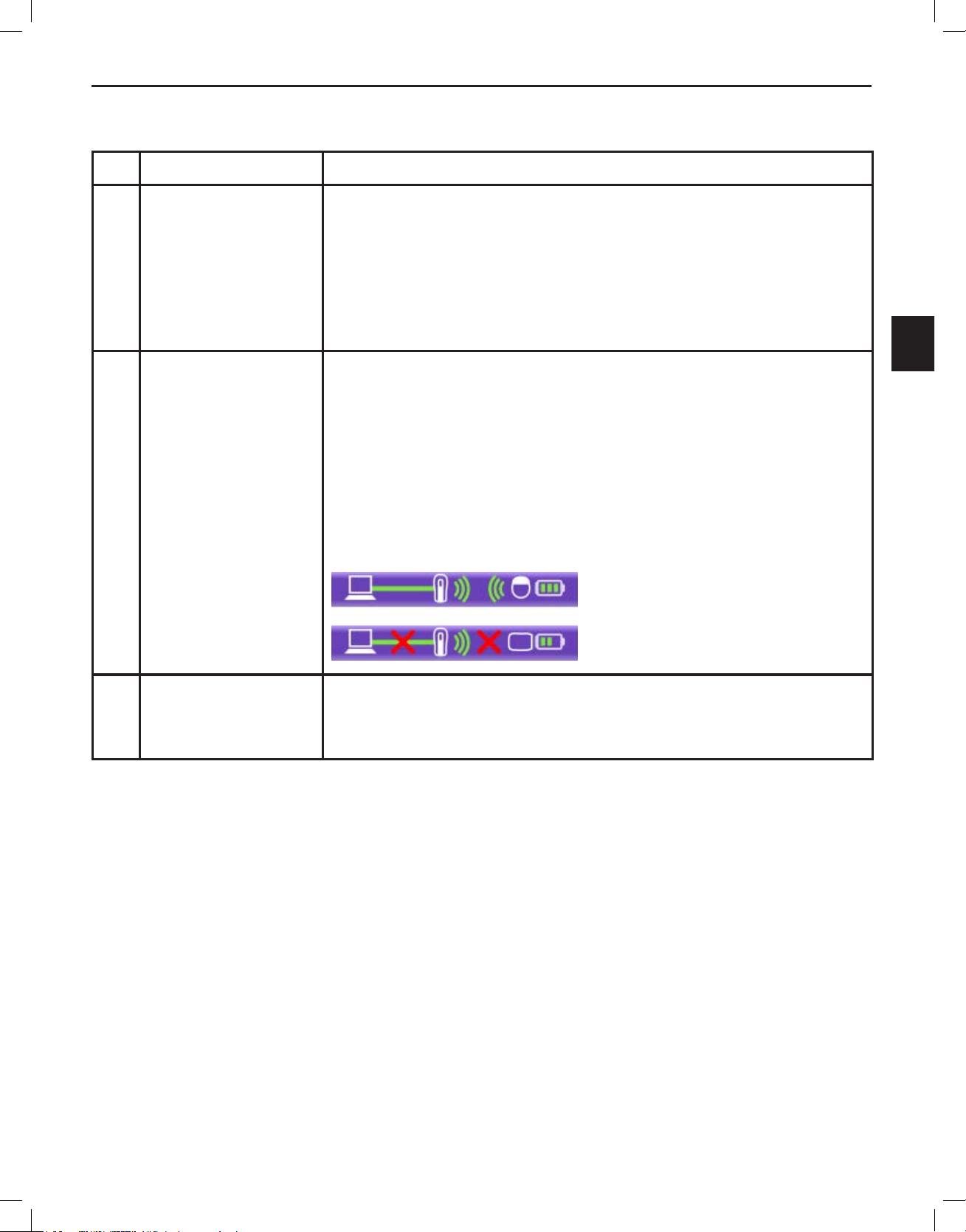
4 Stimulation On/Off
Button
5
Notes
The Stimulation On/Off button displays at the top of every screen
and changes color to indicate connection status as well as stimulation
On/Off status:
The CP is not connected to a Stimulator.
The CP is connected to a Stimulator; and stimulation is OFF.
The CP is connected to a Stimulator, and stimulation is ON.
When the CP is connected to a Stimulator, you can turn stimulation on
or off at anytime by selecting the Stimulation On/Off button.
Displays the Notes pop-up window which allows you to:
• Select a reason for the visit.
6
7
8
Reports
Tools
Quit
• Record Session Notes.
• View the Notes History.
Displays the Reports pop-up window which allows you to generate
and print customizable reports.
Displays the Tools pop-up window which allows you to:
• Increase or decrease the default value for pulse width and rate.
• Specify which parameters are locked out on the remote control.
• Backup data and logs.
• Enable or disable leads.
Displays the Quit pop-up window which allows you to:
• Disconnect from the Stimulator.
• Exit the Clinician Programmer Software
• Turn Off the CP.
Bionic Navigator™ 3D Programming Manual
90930923-31 REV A 6 of 309
Page 11

Starting a Session
en
Entering Patient Information
From the Main screen, select the Patient Expander Bar to access the Patient Info screen (default) and
the Pain Scale screen.
Figure 3: Patient Info Screen
Note: Required elds on the screen above are indicated by an asterisk.
The Patient Info
and Pain Scale buttons on the left side of the Patient screen allow you
to toggle between the Patient Info screen and the Pain Scale screen. See “Defining a Patient’s Pain” for
additional information.
To enter/edit information on the Patient (Information) screen:
1. Type the Patient/Chart ID (Optional)
2. Type the Patient’s Last Name.
3. Type the Patient’s First Name.
Bionic Navigator™ 3D Programming Manual
90930923-31 REV A 7 of 309
Page 12

Bionic Navigator™ 3D Programming Manual
en
4. Select the calendar icon to select the Date of Birth. Tip: To quickly change the birth year,
click or tap twice on the [Month, Year] at the top of the calendar to be able to scroll (left-right)
to different decades.
5. Select the Patient’s Gender: (Optional)
a. Female
b. Male
6. Type the Patient’s Address. (Optional)
7. Type the name of the Physician, or select from the drop-down list. (Optional)
Note: This text box is enabled only when the CP is connected to a Stimulator. See Connecting
to a Stimulator in this manual.
8. Type the Diagnosis, or select from the drop-down list. (Optional)
Note: This text box is enabled only when the CP is connected to a Stimulator. See Connecting
to a Stimulator in this manual.
9. Select the Save button to save the information entered.
Important: Ofine changes will only be saved on the CP.
Note: You can revert to the last saved version of the patient’s information by selecting the
Revert button on the Patient (Information) screen.
Note: To create a new patient record, select the Create New Patient button and repeat steps
1-9 as appropriate.
Bionic Navigator™ 3D Programming Manual
90930923-31 REV A 8 of 309
Page 13
Starting a Session
en
Changing Patients
You can choose to display information for a different patient, when the CP is not connected to a
stimulator, by selecting the Change Patient button on the Patient Info screen. The Select a patient
pop-up window will be displayed:
Figure 4: Select a Patient Pop-Up Window
Note: Use the scroll bars at the bottom and side of the pop-up window to view all of the available
information.
To Change a Patient:
1. Type any part of the Patient’s name in the Search text box to narrow the list.
2. Select the Patient’s name from the list.
3. Select the Assign Patient button.
Bionic Navigator™ 3D Programming Manual
90930923-31 REV A 9 of 309
Page 14

Bionic Navigator™ 3D Programming Manual
en
Dening the Patient’s Pain
From the Patient Info screen, select the Pain Scale button to display the Pain Scale screen.
Note: A Stimulator must be connected to the CP in order to access the Pain Scale screen. Refer to
“Connecting to a Stimulator”.
Figure 5: Pain Scale Screen
Note: As indicated on the Pain Scale screen in Figure 5, 0 represents No Pain and 10 represents the
Worst Pain Imaginable.
Bionic Navigator™ 3D Programming Manual
90930923-31 REV A 10 of 309
Page 15

en
To enter a Patient’s Pain Scale:
1. Select the Sliding Number button on the Stimulation ON bar and slide it to the number that
best represents the Patient’s level of pain when stimulation is ON.
2. Select the Sliding Number button on the Stimulation OFF bar and slide it to the number that
best represents the Patient’s level of pain when stimulation is OFF.
Note: Stimulation can be turned on and off at any time, by selecting the Stimulation On/Off
button at the top of the screen.
Starting a Session
Bionic Navigator™ 3D Programming Manual
90930923-31 REV A 11 of 309
Page 16
Bionic Navigator™ 3D Programming Manual
en
Conguring the CP and Stimulator
The Configuration screen allows you to set up the CP and Stimulator for programming. On the
Configuration screen you can:
• Establish a programming connection between the CP and the Stimulator.
• Check the status of the programming connection.
• Identify which leads are used and record where they were implanted.
• Set up the connection between the leads and the Stimulator ports.
• Run LeadSync™ to identify and apply the relative offset of leads.
• Check the impedances of each contact.
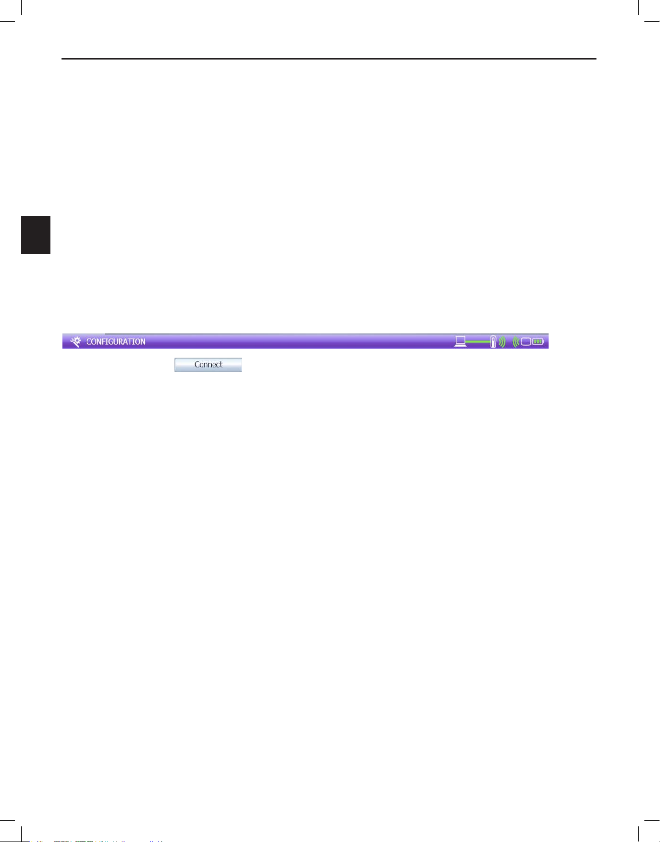
Connecting to a Stimulator
In order to program a Stimulator, you must connect the CP to that Stimulator.
1. Select the Conguration Expander bar to display the Connect screen.
2. Select the button to create a programming connection between the desired
Stimulator and CP. The Connection Status Indicator displays green when a valid connection
is made.
Note: After connecting the desired Stimulator and CP, a Remote Control (and in the case of an ETS,
also the ETS On/Off button) can be used to modify the Stimulator’s settings” (e.g., turn stimulation ON
or OFF). Any subsequent change to the Stimulator from the CP will transfer the settings displayed on
the CP to the Stimulator.
Caution: If the Remote Control is used to turn stimulation OFF during programming, turn the
Stimulation On/Off Button on the CP to OFF before resuming programming. This will ensure that
the CP is synchronized with the stimulation status of the Stimulator.
Bionic Navigator™ 3D Programming Manual
90930923-31 REV A 12 of 309
Page 17

Conguring the CP and Stimulator
en
Figure 6: Connection Screen
Component Description
1 CP to Wand to
Stimulator Connection
Displays the status of the connections between the CP, Wand, and
Stimulator.
2 Rescan Button Select this button to rescan the vicinity for available Stimulators.
(Disabled if CP is already connected to a Stimulator)
Bionic Navigator™ 3D Programming Manual
90930923-31 REV A 13 of 309
Page 18

Bionic Navigator™ 3D Programming Manual
en
3 Stimulator Information
Note: When the
Connect screen is
rst accessed, the
CP scans the vicinity
to locate and lists all
available Stimulators.
Displays the following:
• Type of Stimulator (Trial Stimulator or Implantable Pulse
Generator)
• Model Number
• Serial Number
• Firmware Version Number
• Stimulator service life information, if within the End of Battery
life or ERI (elective replacement indicator) period for nonrechargeable stimulators or within 6 months of the planned end of
service life date for all stimulators.
4 Patient Information Last Name, First Name, and Date of Birth are displayed if the
Stimulator is assigned to a patient. If not, these fields are blank.
Refer to “Assigning a Patient to a Stimulator”.
5 Disassociate Button Select this button to disassociate the displayed patient from the
connected stimulator.
6 Connection Status
The indicator displays a green filled circle if the Stimulator is
Indicator
7 Connect or
Disconnect Button
connected to the CP.
When no stimulator is connected, this button reads “Connect”. When
a Stimulator is connected, this button reads “Disconnect”.
Select the button to Connect or Disconnect the desired stimulator.
Bionic Navigator™ 3D Programming Manual
90930923-31 REV A 14 of 309
Page 19

Conguring the CP and Stimulator
en
Figure 7: Connection Screen after Trial Stimulator is Connected
Bionic Navigator™ 3D Programming Manual
90930923-31 REV A 15 of 309
Page 20

Bionic Navigator™ 3D Programming Manual
en
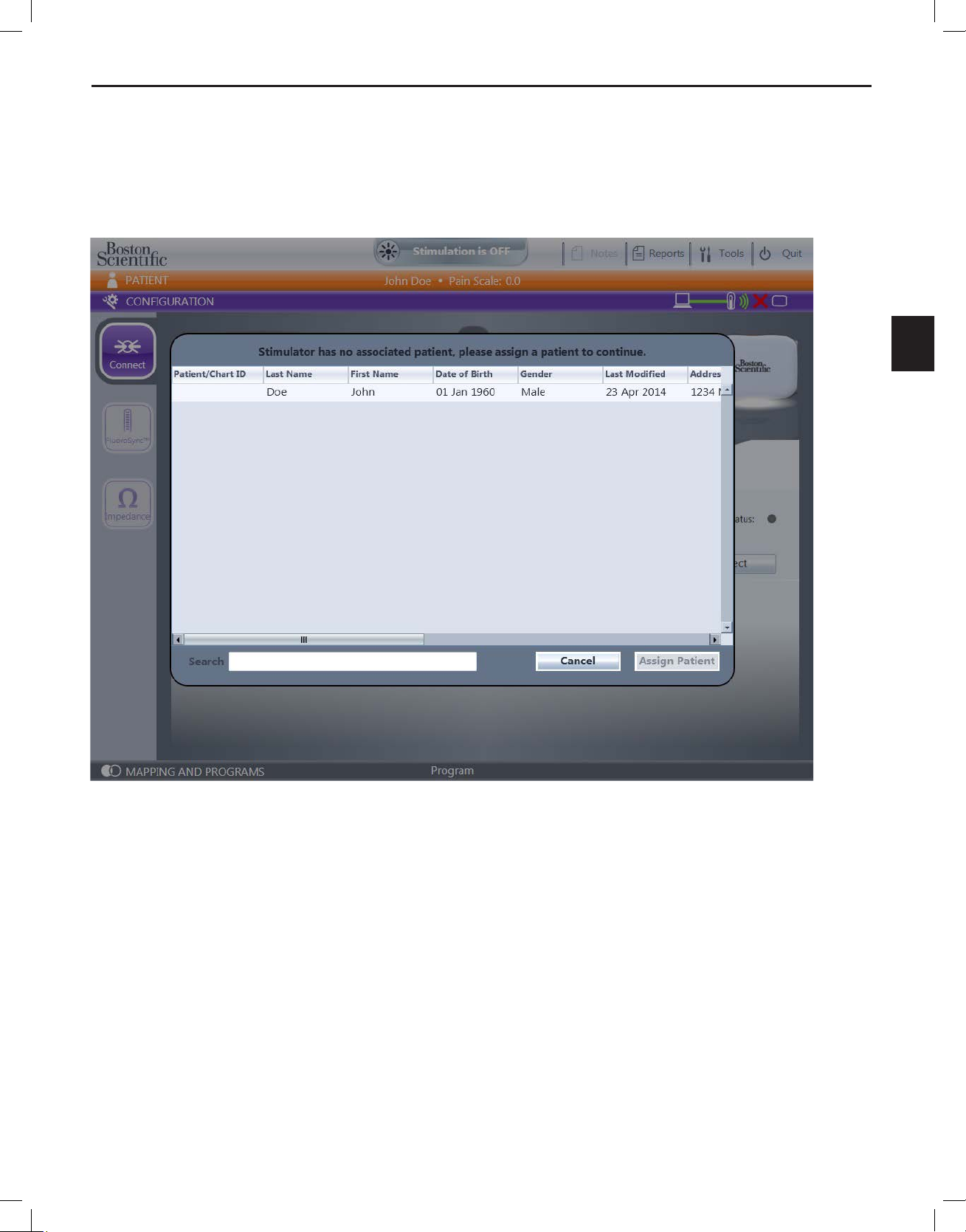
Assigning a Patient to a Stimulator
A patient profile must be associated with a Stimulator before a Stimulator can be programmed. If a
Stimulator is not assigned a patient profile, the software prompts you to assign a patient profile from the
patient profile database on the CP.
Figure 8: Change Patient Dialog Box
1. If desired, type the rst name, last name or Patient/Chart ID in the Search text box to lter
the list of Patients.
2. Select the appropriate Patient.
3. Select the Assign Patient button.
Bionic Navigator™ 3D Programming Manual
90930923-31 REV A 16 of 309
Page 21

Conguring the CP and Stimulator
en
Choosing a Patient Record to Use
During the connection process, if the Patient information in the Stimulator and the Patient information in
the CP database differ, you will be prompted to select which Patient record to use.
Figure 9: Change Patient Record Dialog Box
1. Review the Patient records.
2. Select the Use this Record button for the record that you want to save to the Stimulator and
to the CP. The record that is not selected will be overwritten.
Bionic Navigator™ 3D Programming Manual
90930923-31 REV A 17 of 309
Page 22

Bionic Navigator™ 3D Programming Manual
en
Disassociating a Patient
You can disassociate or remove a patient profile from a Stimulator.
Note: The Disassociate button only displays on the Configuration Connect screen when a Patient
profile is assigned to a Stimulator.
From the Connect screen:
1. Select the
button for the Stimulator to which the Patient is currently
associated.
2. The Patient prole is removed from the Stimulator and the programming connection
between the CP and the Stimulator is terminated. For the ETS, all programming, usage, and
lead conguration data are also removed.
Viewing the Programming Connection Status
The programming connection status between the CP, Programming Wand, and Stimulator is displayed
on the Connect screen.
Figure 10: Connected Status
Figure 11:
Bionic Navigator™ 3D Programming Manual
90930923-31 REV A 18 of 309
Disconnected Status
Page 23

Conguring the CP and Stimulator
en
Displaying CP and Programming Wand Information
You can view additional information for the CP or Programming Wand from the Connect screen.
1. Select the CP image to display the following CP information:
• System Date
• System Time
• Installation Conrmation Key
• Install Date
• Software Version
• Software Part Number
Figure 12: Connection Screen, CP Information
Bionic Navigator™ 3D Programming Manual
90930923-31 REV A 19 of 309
Page 24

Bionic Navigator™ 3D Programming Manual
en
2. Select the Wand image to display the following information:
• Model Number
• Serial Number
• Firmware Part Number
Figure 13: Connection Screen, Wand Information
3. Re-select the Stimulator image to display the Stimulator information (Connection screen’s
default view):
• Model Number
• Serial Number
• Firmware version
NOTE: The Model number and Serial number of the Trial Stimulator can be found by removing the
battery compartment on the Trial Stimulator.
Bionic Navigator™ 3D Programming Manual
90930923-31 REV A 20 of 309
Page 25

Conguring the CP and Stimulator
en
Conguring Leads
Before programming can begin, leads must be selected, positioned, and connected to the Stimulator on
the Leads screen.
Compatible Leads:
• Innion™ 16 xxcm 16 Contact Lead
• Innion CX xxcm 16 Contact Lead
• Linear™ xxcm 8 Contact Lead
• Linear ST xxcm 8 Contact Lead
• Linear 3-4 xxcm 8 Contact Lead
• Linear 3-6 xxcm 8 Contact Lead
• Artisan™ 2x8 Surgical Lead
• CoverEdge™ 32 xxcm 4x8 Surgical Lead
• CoverEdge X 32 xxcm 4x8 Surgical Lead
• 8 Contact Extensions
• 2x4 Splitters
• 2x8 Splitters
• Avista™ MRI xxcm 8 Contact Lead
Note: xx denotes length (cm)
The Precision Spectra System supports 32 contact surgical leads, and any combination of 8 contact
percutaneous, 16 contact percutaneous and 16 contact surgical leads totaling up to 32 active contacts.
The Precision Novi and Precision Montage MRI Systems support 16 contact (2x8) surgical leads,
16 contact percutaneous leads, and a combination of 8 contact percutaneous leads, totaling up to
16 active contacts.
The Avista MRI Lead is only compatible with the Precision Montage MRI System.
Bionic Navigator™ 3D Programming Manual
90930923-31 REV A 21 of 309
Page 26

Bionic Navigator™ 3D Programming Manual
en
The Leads (FluoroSync™) screen can be accessed by selecting the FluoroSync button from
the Configuration screen.
When connected to a 4-port
stimulator, the Leads screen shows
ports A, B, C and D.
Note: Throughout this manual, the
Leads screen is shown connected
to a 4-port stimulator
Figure 14a: FluoroSync Screen when connected to a 4-port stimulator
When connected to a 2-port
stimulator, the Leads screen shows
ports C and D.
Figure 14b: FluoroSync Screen when connected to a 2-port stimulator
Bionic Navigator™ 3D Programming Manual
90930923-31 REV A 22 of 309
Page 27

en
The features on the Leads screen are described in the following table:
Panel Description
Conguring the CP and Stimulator
1 Lead Selection
Panel
2 Lead Placement
Panel
Displays all supported percutaneous and paddle leads for the Stimulator.
Note:
• 1x8 percutaneous = lead included in the Linear (ST) xxcm 8 Contact
Lead kits and Avista MRI xxcm 8 Contact Lead kits. All other 8 contact
Linear leads and Splitter congurations may be programmed using
this lead. Manual mode may be used to account for different contact
spacing.
• 1x16 percutaneous = lead included in the Innion xxcm 16 Contact Lead
kits or in the Innion CX xxcm 16 Contact Lead kits
• 2x8 paddle = Artisan xxcm 2x8 Surgical Lead kits
• 4x8 paddle (tightly-spaced) = CoverEdge 32 xxcm 4x8 Surgical Lead kits
• 4x8 paddle (widely-spaced) = CoverEdge X 32 xxcm 4x8 Surgical Lead
kits
Note: xx denotes lead length.
Illustrates and records the vertebral level of the spinal column where leads
are placed.
3 Placement/Grid
Lines
Illustrates and records the mediolateral placement of the leads. A lead
can be dragged and dropped on to one of seven Grid Lines on the Lead
Placement Panel. Note: After placing the first percutaneous lead in a
Lead Group, only alternating Grid Lines will be available for additional
percutaneous leads that are placed in that Lead Group. To view all seven
Grid Lines, remove all but one lead in any Lead Group.
4 Stimulator Ports Displays the OR Cable ports or Implantable Pulse Generator (IPG) ports
available.
5 Trash Can Drag and drop individual leads to the Trash Can to delete.
6 Lead Options
Panel
Contains the following information about a selected lead (features 7
through 9)
7 Description For example, “1x8 Percutaneous”
8 Retrograde
Check Box
If the Retrograde check box is selected, the orientation of the lead has
been rotated 180 degrees (the distal end of lead is positioned caudal to the
insertion point).
9 Lead Group The selected radio button tells you if a lead is in Group 1, 2, 3 or 4. See
“Assigning a Lead to a Group” in this manual for additional information.
Bionic Navigator™ 3D Programming Manual
90930923-31 REV A 23 of 309
Page 28

Bionic Navigator™ 3D Programming Manual
en
10 LeadSync Scan
Initiates an electronic lead scan. Refer to “Using LeadSync Technology”.
Button
1. Drag the desired lead from the Lead Selection Panel into the appropriate vertebral level
and medio-lateral position within the Lead Placement Panel. When dropped the lead snaps
horizontally to the nearest Grid Line.
2. Connect the tail(s) of the lead(s) to the appropriate header port. Select the numbered circle
of the tail and drag it over the appropriate port and release.
Note: The 1x8 percutaneous lead displays one tail that corresponds to all eight contacts. The 1x16
percutaneous lead displays two tails: the rst tail corresponds to the contacts 1-8 on the distal end of
the lead and the second tail corresponds to contacts 9-16. The 2x8 paddle lead displays two tails: the
rst tail corresponds to the left column of eight contacts and the second tail corresponds to the right
column of eight contacts. The 4x8 paddle leads display four tails:
• The rst tail with one marker band corresponds to the rst column of contacts (1-8).
• The second tail with two marker bands corresponds to the second column of 8 contacts (9-16).
• The third tail with three marker bands corresponds to the third column of 8 contacts (17-24).
• The fourth tail with four marker bands corresponds to the fourth column of 8 contacts (25-32).
Note: Check to be sure that each tail has been correctly assigned to the appropriate port.
Bionic Navigator™ 3D Programming Manual
90930923-31 REV A 24 of 309
Page 29

Conguring the CP and Stimulator
en
Figure 15: Lead Conguration with two percutaneous leads placed.
Bionic Navigator™ 3D Programming Manual
90930923-31 REV A 25 of 309
Page 30

Bionic Navigator™ 3D Programming Manual
en
Changing a Lead’s Orientation on the Lead Placement Panel
From the Leads screen:
1. Select a lead.
2. Select the Retrograde check box to ip the lead 180 degrees, so that the distal end is
pointing caudally and the proximal tails emerge from the rostral end of the lead.
3. If desired, uncheck the Retrograde check box to ip the lead back to its original (default)
position.
Figure 16: Changing Lead Orientation
Bionic Navigator™ 3D Programming Manual
90930923-31 REV A 26 of 309
Page 31

Conguring the CP and Stimulator
en
Assigning a Lead to a Group
Lead Groups specify which leads should be programmed together in automated programming modes
(for example, to create an independent stimulation field).
Note: Multiple percutaneous leads can be grouped together, but any paddle lead must be in its own
Lead Group. In manual programming mode, you can program across lead groups.
The first lead dropped into the Lead Placement Panel is assigned to Group 1. Each subsequent
percutaneous lead dropped into this panel is assigned to the Group of whichever lead is currently
selected. Lead Group assignments can be changed by selecting a lead then selecting one of the four
radio buttons for Lead Groups; however, the target Lead Group must be empty. To add a new lead to
a Lead Group that already has a percutaneous lead assigned to it, a new lead must be added from the
Lead Selection Panel on the left.
When a Paddle lead is dropped into the Lead Placement Panel, it is assigned to its own Lead Group, if
an empty Lead Group is available. Additional leads cannot be added to Lead Groups that are already
occupied by a paddle lead.
IMPORTANT: Only leads that are in the same Lead Group will interact to program a stimulation Area,
except when programming in Manual mode. Refer to “Using Manual Mode”.
1. Drag and drop the desired lead onto the Lead Placement Panel. As stated earlier, the rst
lead dropped will be automatically assigned to Group 1.
2. Subsequent percutaneous leads dropped onto the Lead Placement Panel will be added
to Group 1. When a paddle lead is dropped, it will be assigned to its own Lead Group if an
empty Lead Group is available.
3. Lead Groups can be modied by selecting the desired lead, then selecting a different Lead
Group radio button on the right of the screen.
Bionic Navigator™ 3D Programming Manual
90930923-31 REV A 27 of 309
Page 32

Bionic Navigator™ 3D Programming Manual
en
Using LeadSync™ Technology
LeadSync technology allows you to measure the relative rostrocaudal orientation between two or more
leads in the same Lead Group. Select the LeadSync button on the lower right hand corner of the Leads
screen. The LeadSync pop-up window will display the results for the first Lead Group.
Figure 17: LeadSync Pop-Up Window
Bionic Navigator™ 3D Programming Manual
90930923-31 REV A 28 of 309
Page 33

Conguring the CP and Stimulator
en
The components on the LeadSync pop-up window are described in the table below.
Component Description
1 Lead Group drop-down list Allows you to select a specific Lead Group to review.
2 Cancel button Discards the LeadSync results for the Lead Group shown.
3 Rescan button Re - runs LeadSync for all Lead Groups.
4 Apply button Allows you to accept the LeadSync results for the Lead Group
shown, adjusting the relative alignment of the leads accordingly.
5 Close button Closes the LeadSync pop-up window to return to the Leads
Screen.
The image displayed on the LeadSync pop-up window may display a different relative lead orientation
than what was configured in the Leads Placement panel. Between each pair of leads is a symbol
indicating the correlation of the LeadSync measurement to the displayed lead offset, as the LeadSync
measurement is dependent on the geometry of the actual lead placement. There are three symbols that
describe LeadSync measurement results:
Correlation of LeadSync Measurement to the displayed lead offset is high. See Figure 18.
Correlation of LeadSync Measurement to the displayed lead offset is low. See Figure 19.
LeadSync is unable to provide meaningful result and will display the lead configuration that
was manually specified by user. See Figure 20.
Bionic Navigator™ 3D Programming Manual
90930923-31 REV A 29 of 309
Page 34

Bionic Navigator™ 3D Programming Manual
en
Figure 18: LeadSync with Check Mark - A check mark in a green circle indicates that correlation of LeadSync
Measurement to the displayed lead offset is high. If the displayed LeadSync measurement is applied, the leads will
be re-aligned with respect to the center of the Lead Group and displayed in the Leads Placement panel.
Bionic Navigator™ 3D Programming Manual
90930923-31 REV A 30 of 309
Page 35

Conguring the CP and Stimulator
en
Figure 19: LeadSync with Question Mark - A question mark in a yellow circle indicates that the correlation of
LeadSync Measurement to the displayed lead offset is low. If the displayed LeadSync measurement is applied, the
leads will be re-aligned with respect to the center of the Lead Group and displayed in the Leads Placement panel.
Bionic Navigator™ 3D Programming Manual
90930923-31 REV A 31 of 309
Page 36

Bionic Navigator™ 3D Programming Manual
en
Figure 20: LeadSync with X – An “x” in a yellow circle indicates that LeadSync was unable to provide meaningful
result and will display the lead conguration that was manually specied by user. Applying this LeadSync result will
not result in any lead orientation changes.
Bionic Navigator™ 3D Programming Manual
90930923-31 REV A 32 of 309
Page 37

Conguring the CP and Stimulator
en
Measuring Impedances
Impedance values can be measured at each contact. From the Configuration - Leads screen, select
the Impedances
screen.
button to measure impedances and display the Configuration - Impedances
Figure 21: Impedances Screen
The results of the Impedance measurement at each contact are displayed in terms of the stimulator
port connections as seen in Figure 21. If desired, you can select the Measure button again to perform
another Impedance measurement.
A green circle indicates that the impedance measurement is less than 8000 ohms. An orange circle
indicates that the measurement is above 8000 ohms with reduced accuracy. In Figure 21, Contacts C1,
C2, and D1-8 are displaying impedances above 8000 ohms.
Bionic Navigator™ 3D Programming Manual
90930923-31 REV A 33 of 309
Page 38

Bionic Navigator™ 3D Programming Manual
en
Note: High impedance values starting from Contact 1 on the A, B, C, or D ports may indicate that a
lead is not properly seated in the OR Cable or IPG header. In Figure 21, the results for Port C and
D may indicate that the lead was not fully inserted into the IPG header. For stimulators with only
16 contacts, only Ports C and D will be shown.
To print the impedance measurements, select the Print button on the Configuration-Impedances
screen.
Bionic Navigator™ 3D Programming Manual
90930923-31 REV A 34 of 309
Page 39

Programming the Patient
en
Programming the Patient
After the stimulator connection has been established and the leads have been configured, you are now
ready to program the stimulator, which is performed in the Mapping and Programs screen. To access
the Mapping and Programs screen, select the Mapping and Programs Expander Bar. This expander
bar is accessible only when:
• A Stimulator is connected (see Connecting to a Stimulator)
• Leads have been congured and connected to the Stimulator (see Conguring Leads)
There may be a delay while the lead configuration is downloaded to the Stimulator.
Precision Spectra Programmable Parameters
Parameter Range Default
Amplitude 0 - 25.5 mA 0 mA
Rate 2 – 1200 Hz
Pulse Width 20 – 1000 µs
Cycling OFF
Cycle ON 1 sec – 90 min -
Cycle OFF 1 sec – 90 min -
Ramp On Time 1 – 10 sec 3 sec
Programmable Contacts Precision Spectra: 32 + IPG case (Anode/Cathode/Off) Off
Independent Areas of Stimulation per Program 4 N/A
Available Programs 16 N/A
a. Only one Area is available if the rate is >130 pps.
b. Amplitude × Width ≤ 12.7 μC for all leads other than the 4x8 surgical Lead; Amplitude × Width ≤ 10.6 μC for the 4x8 surgical lead.
a
b
40 Hz
210 μs
Bionic Navigator™ 3D Programming Manual
90930923-31 REV A 35 of 309
Page 40

Bionic Navigator™ 3D Programming Manual
en
Maximum Current Amplitude per Electrode Vs Impedance
(for all leads other than the 4x8 Surgical Lead)
Programmable up to 25.5 mA
25.50
Programmable up to 21.1 mA
20.40
Programmable up to 15.8 mA
15.30
Current (mA)
10.20
Current (mA)
Programmable up to 12.7 mA
5.10
0.00
300 400 500 600 700 800 900 1000 1100 12 00
Maximum Amplitude Based on Impedance and Pulse Width
Impedance (Ω)
Impedance (Ω)
Maximum Current Amplitude per Electrode Vs Impedance
(for the 4x8 Surgical Lead)
Pulse Width:
PW = 20 us
20 µsec
PW = 100 us
100 µsec
PW = 200 us
200 µsec
300 µsec
PW = 300 us
400 µsec
PW = 400 us
600 µsec
PW = 600 us
800 µsec
PW = 800 us
1000 µsec
PW = 1000 us
Programmable up to 25.5 mA
25.50
20.40
Programmable up to17.6 mA
15.30
Current (mA)
10.20
Current (mA)
Programmable up to 13.2 mA
Programmable up to 10.6 mA
5.10
0.00
300 400 500 600 700 800 900 1000 1100 12 00
Maximum Amplitude Based on Impedance and Pulse Width
Impedance (Ω)
Impedance (Ω)
Pulse Width:
PW = 20 us
20 µsec
PW = 100 us
100 µsec
PW = 200 us
200 µsec
300 µsec
PW = 300 us
400 µsec
PW = 400 us
600 µsec
PW = 600 us
800 µsec
PW = 800 us
1000 µsec
PW = 1000 us
Bionic Navigator™ 3D Programming Manual
90930923-31 REV A 36 of 309
Page 41

en
Maximum Amplitude Based on Frequency and Pulse Width
(for all leads other than the 4x8 Surgical Lead)
Maximum Amplitude Based on Frequency and Pulse Width
25.50
Programming the Patient
20.40
15.30
Current (mA)
10.20
Current (mA)
5.10
0.00
0 200 400 600 800 1000 1200
Frequency (Hz)
Frequency (Hz)
Maximum Amplitude Based on Frequency and Pulse Width
(for the 4x8 Surgical Lead)
Maximum Amplitude Based on Frequency and Pulse Width
25.50
Pulse Width:
PW = 20 us
PW = 100 us
PW = 200 us
PW = 300 us
PW = 400 us
PW = 600 us
PW = 800 us
PW = 1000 us
20.40
15.30
Current (mA)
10.20
Current (mA)
5.10
0.00
0 200 400 600 800 1000 1200
Frequency (Hz)
Frequency (Hz)
Bionic Navigator™ 3D Programming Manual
Pulse Width:
PW = 20 us
20 µsec
PW = 100 us
100 µsec
PW = 200 us
200 µsec
PW = 300 us
300 µsec
400 µsec
PW = 400 us
600 µsec
PW = 600 us
800 µsec
PW = 800 us
1000 µsec
PW = 1000 us
90930923-31 REV A 37 of 309
Page 42

Bionic Navigator™ 3D Programming Manual
en
Precision Novi and Precision Montage MRI Programmable Parameters
Parameter Range Default
Amplitude 0 - 25.5 mA 0 mA
Rate 2 – 1200 Hz
Pulse Width 20 – 1000 µs
Cycling OFF
Cycle ON 1 sec – 90 min
Cycle OFF 1 sec – 90 min
Ramp On Time 1 – 10 sec 3 sec
Programmable Contacts Precision Novi: 16 + IPG case (Anode/Cathode/Off)
a
b
40 Hz
210 μs
-
-
OFF
Precision Montage MRI: 16 + IPG case (Anode/Cathode/Off)
Independent Areas of Stimulation per Program 4 N/A
Available Programs 16 N/A
a. Only one Area is available if the rate is >130 pps.
b. Amplitude × Width ≤ 12.7 μC.
Maximum Current Amplitude per Electrode Vs Impedance
AMP (mA)
Pulse Width:
20 µsec
100 µsec
200 µsec
300 µsec
400 µsec
600 µsec
800 µsec
1000 µsec
Bionic Navigator™ 3D Programming Manual
90930923-31 REV A 38 of 309
Impedance (Ω)
Page 43

en
Maximum Amplitude Based on Frequency and Pulse Width
Current (mA)
Programming the Patient
Pulse Width:
20 µsec
100 µsec
200 µsec
300 µsec
400 µsec
600 µsec
800 µsec
1000 µsec
Frequency (Hz)
Bionic Navigator™ 3D Programming Manual
90930923-31 REV A 39 of 309
Page 44

Bionic Navigator™ 3D Programming Manual
en
Mapping and Programs Screen
Figure 22: Mapping and Programming Screen
Stimulation settings can be saved in a Program with up to four independent stimulation fields or Areas.
For example, one Area may correspond to a target in the legs, while another Area may correspond to
a target in the low back. Stimulation parameters and the contact configuration are displayed for one
selected Area at a time.
Overview
The Mapping and Programs screen is divided into 3 sections: the Basic Panel, the Parameters Panel,
and the Lead Group Panel. The Basic Panel displays all of the individual Programs that are saved into
the Remote Control, as well as the stimulation Areas that constitute each Program. The Parameters tab
reveals the Parameters panel. The Parameters Panel displays settings for programming. The Full View
tab reveals both the Parameters Panel and the Lead Group Panel. The Lead Group Panel displays the
electrode configuration for the selected lead group, and enables selection of other lead groups.
Bionic Navigator™ 3D Programming Manual
90930923-31 REV A 40 of 309
Page 45
en
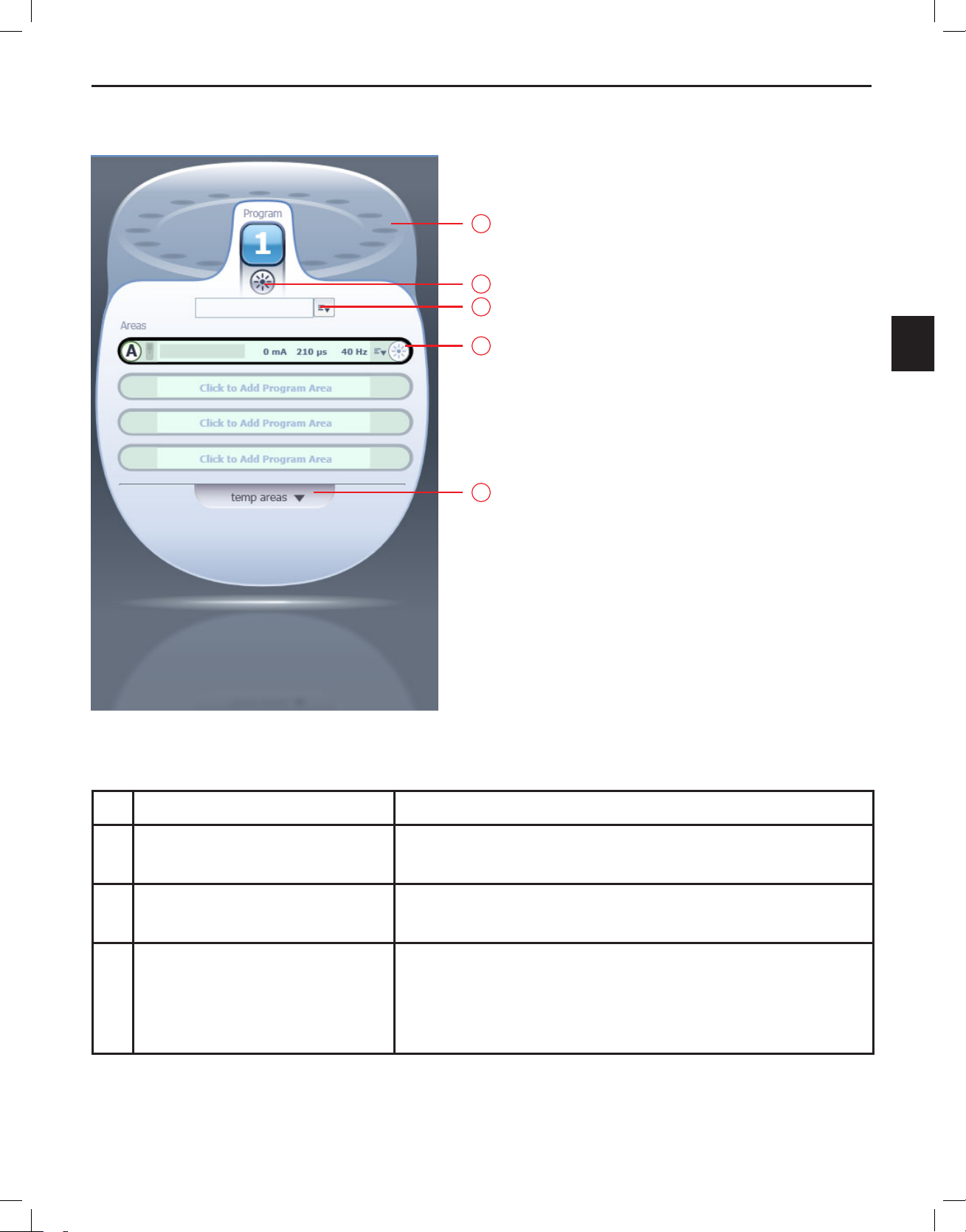
Basic Panel
Programming the Patient
1
2
3
4
5
Figure 23:
Basic Panel
The components on the Basic Panel are described in the table below.
Component Description
1 Program Carousel Used to access program slots for storing or creating up to
16 patient Programs.
2 Program ON/OFF Button Turns stimulation ON or OFF for the current, active Program.
Refer to “Turning Stimulation ON or OFF”.
3 Program Name and Program
Options Menu
A name for the current program can be entered in this field.
Program Options for the active Program can be viewed by
selecting on the down arrow next to the Program Name field.
Refer to “Understanding the Program Options”.
Bionic Navigator™ 3D Programming Manual
90930923-31 REV A 41 of 309
Page 46
Bionic Navigator™ 3D Programming Manual
en
4 Area Slot A Program can have up to four Areas. Each Area has its own
5 Temporary Areas Expander During programming, there may be a need to temporarily
Parameters Panel
When the Parameters Tab is selected, only the Parameters Panel will be expanded. However, when the
Full View Tab is selected, both the Parameters Panel and the Lead Group Panel will be expanded.
The Parameters Panel displays controls for changing the stimulation parameters for the Area or for the
Program, which are accessed by two distinct tabs. There is one stimulation parameter that is available
for configuring a Program – total amplitude. There are three stimulation parameters that are available to
you for configuring an Area – amplitude, pulse width, and rate. The amplitude of stimulation is the peak
value of a stimulation pulse and is measured in milliamps (mA). The pulse width of the stimulation
dedicated slot, which displays the parameters programmed
for that Area. Refer to “Understanding the Area Slots”.
store a specific configuration for later use. These can be
stored here. Refer to “Temporarily Saving Areas”.
describes the length of time a stimulation pulse is applied to the area. The pulse width is measured
in microseconds (μs). The rate (or frequency or pulse rate) of the stimulation dictates how often a
stimulation pulse is delivered in one second. The rate of stimulation is measured in Hertz (Hz).
Bionic Navigator™ 3D Programming Manual
90930923-31 REV A 42 of 309
Page 47

Programming the Patient
en
1
2
3
4
6
5
7
Figure 24: Parameters Panel
The components on the Parameters Panel are described in the table below.
Component Description Availability
1 Amplitude Control Increases (“+”) or decreases (“-“)
stimulation amplitude. Refer to “Increasing/
Decreasing Amplitude”.
2 Pulse Width
Control
Increases (“+”) or decreases (“-“)
the stimulation pulse width. Refer to
“Increasing/Decreasing Pulse Width”.
3 Rate Control Increases (“+”) or decreases (“-“) the
stimulation pulse rate. Refer to “Increasing/
Decreasing Rate”.
Program Tab, Area Tab
Area Tab
Area Tab
4 Programming
Mode Drop-Down
List
Changes Programming Mode. Refer to
“Electrode Programming”.
Area Tab
Bionic Navigator™ 3D Programming Manual
90930923-31 REV A 43 of 309
Page 48

Bionic Navigator™ 3D Programming Manual
en
5 Advanced Options
Tab
When expanded, displays Resolution
and Focus controls. Refer to “Selecting
Area Tab (E-Troll™ and
Navigate Modes only)
Advanced Options”.
6 Polarity and
Percentage Control
Use to change polarity (cathode or anode)
and percentage after selecting an individual
Area Tab (Manual Mode
only)
contact or the case.
7 Equalize Control Use to equally distribute all cathodic or
anodic current among active contacts in the
Area Tab (Manual Mode
only)
selected Area
Full View Tab
Expanding the Full View Tab will display the Lead Group panel, showing configured leads in each Lead
Group. This will help visualize what contacts are being used as you are programming.
2
3
1
Figure 25:
Bionic Navigator™ 3D Programming Manual
90930923-31 REV A 44 of 309
Full View Panel
Page 49

Programming the Patient
en
The components on the Full View Panel are described in the following table.
Component Description
1 Leads View Displays leads and electrode programming for the selected Lead Group.
2 Lead Group Tabs Allow selection of a Lead Group. One tab is available for each of the 4
Lead Groups
3 Central Point of
Stimulation
Center of stimulation field for the electrode combination, as denoted by
the circled letter A, B, C, or D, such as:
Refer to “Electrode
Programming” for additional information. Note: This is not available in
Manual Mode.
Selecting the Program
There are 16 Program slots available for programming. These Programs are arranged in a carousel in
the Basic Panel. When a Program is selected, it will appear in the forefront, but stimulation will be off by
default.
Figure 26: Occupied Slots on the Carousel
Bionic Navigator™ 3D Programming Manual
90930923-31 REV A 45 of 309
Page 50

Bionic Navigator™ 3D Programming Manual
en
Once a slot is accessed and configured, that slot will be considered occupied. A numerical placeholder
that looks like
will occupy that slot to signify that the slot has been programmed.
Note: The name of the Program that is currently running is displayed on the Mapping and Programs
Expander Bar. See Figure 25.
Electrode Programming
You may program the patient using any of three programming modes: E-Troll, Navigate, and Manual.
In Manual mode, you manually select anodes and cathodes. Electronic Trolling (E-Troll) and Navigate
are both automated programming modes that perform current steering along the electrode array. The
difference between the two is the resolution. E-Troll quickly sweeps the electrode array by moving the
cathode in a bipolar fashion. Navigate mode uses more electrode combinations than E-Troll to fine
tune the coverage. The recommended stimulation settings are calculated using a mathematical model
of field potentials
and tissue resistivity values
physician should not solely depend on this program to optimize stimulation settings.
Note: Manual mode is not available when only the Parameters Tab is expanded.
1,2,6,7
, that are based on average values of tissue properties such as CSF thickness 5
3
that may not be accurate for a given individual subject, and thus, the
Table of Possible Contact Displays
Cathode
Anode
High Impedance. Upon entering the Mapping and Programs screen, high
impedance contacts may be highlighted in red.
Note: The IPG case can also be selected as a cathode or anode.
Bionic Navigator™ 3D Programming Manual
90930923-31 REV A 46 of 309
Page 51

en
Using E-Troll Mode
To program in E-Troll mode for the selected area:
1. Select the Area you would like to program. Note: If a new Area is created, selecting E-Troll
mode will automatically dene the electrode programming so that the Central Point of
Stimulation is at the top left corner of your lead conguration. However, if no changes are
made to the Area, it will not be saved.
2. Select the Lead Group you would like to use. Only one Lead Group can be used per Area.
3. Select E-Troll in the Programming Mode drop-down list.
4. Adjust Amplitude until strength of stimulation is at a comfortable level
5. Use the steering direction arrows to move the Central Point of Stimulation left, right, up, or
down.
6. Adjust Advanced Options as needed. Refer to “Understanding the Advanced Options”.
7. Amplitude, Pulse Width and Rate may be adjusted at any time.
Programming the Patient
Note: When a different Lead Group is selected, any existing electrode conguration for the highlighted
Area will be cleared.
Using Navigate Mode
To program in Navigate mode:
1. Select the Area you would like to program.
2. Select the Lead Group you would like to use. Only one Lead Group can be used per Area.
3. Select Navigate in the Programming Mode drop-down list.
4. Adjust Amplitude until strength of stimulation is at a comfortable level.
5. Use the steering direction arrows to move the Central Point of Stimulation left, right, up, or
down.
6. Adjust Advanced Options as needed. Refer to “Understanding the Advanced Options”.
7. Amplitude, Pulse Width or Rate may be adjusted at any time.
Note: If a new Area was created, selecting Navigate mode will automatically dene the electrode
programming so that the Central Point of Stimulation is at the top left corner of your lead conguration.
Note: When a different Lead Group is selected, any existing electrode conguration for the highlighted
Area will be cleared.
Bionic Navigator™ 3D Programming Manual
90930923-31 REV A 47 of 309
Page 52

Bionic Navigator™ 3D Programming Manual
en
Using Manual Mode
To program in Manual mode:
1. Select the Area you would like to program.
2. Select the Lead Group you would like to start with. Note: Multiple Lead Groups can be
manually programmed within one Area. However, when a conguration for one Area uses
multiple Lead Groups, the user will be unable to switch the programming mode back to
E-Troll or Navigate mode until only one Lead Group is used for that Area.
3. Select Manual in the Programming Mode Drop-Down Menu. Note: If desired, to minimize
the number of contacts with polarity assigned, click on the center of a contact before
selecting Manual in the Programming Mode Drop-Down Menu.
4. Select a contact or the IPG case, and specify the polarity using the Polarity Control (see
Figure 24).
5. Continue selecting contacts and specifying polarities.
6. Optional: the Equalize control to equally distribute all cathodic and or anodic currents as
needed.
7. Adjust Amplitude until strength of stimulation is at a comfortable level.
8. Manually steer current using the Percentage Control (see Figure 24).
9. Amplitude, Pulse Width or Rate may be adjusted at any time.
Manual Mode offers the option of using Prism™ Targeting Technology, which allows placement of
anodic or cathodic current on the IPG.
Note: When the Full View Tab is not expanded, Manual Mode Controls are unavailable. If the user
switches from Manual mode to either E-Troll or Navigate mode during manual programming, the
Central Point of Stimulation will be detected and the electrode conguration will be changed to optimize
stimulation. Any current on the IPG case will be cleared.
Bionic Navigator™ 3D Programming Manual
90930923-31 REV A 48 of 309
Page 53

en
Increasing/Decreasing Amplitude
To increase or decrease the amplitude of the selected Area:
Programming the Patient
1. Select and release the
amplitude. Select and hold the
button under “Amplitude” to incrementally increase the
button to increase amplitude at a faster rate.
Note: Alternatively, the Patient Controller up button may be used.
2. Select and release the
amplitude. Select and hold the
button under “Amplitude” to incrementally decrease the
button to decrease amplitude at a faster rate.
Note: Alternatively, the Patient Controller down button may be used
To increase or decrease the amplitude for all areas that have stimulation turned on:
1. Select the Program Tab in the Parameters Panel.
2. Increase or decrease the amplitude as described above.
Increasing/Decreasing Pulse Width
To increase or decrease the pulse width of the selected Area:
1. Select and release the
button under “Pulse Width” to incrementally increase the pulse
width. Select and hold the
2. Select and release the
width. Select and hold the
button to increase pulse width at a faster rate.
button under “Pulse Width” to incrementally decrease the pulse
button to decrease pulse width at a faster rate.
Note: The Pulse Width control is not displayed when the Program Tab in the Parameters Panel is
selected.
Increasing/Decreasing Rate
To increase or decrease the rate of the selected Area:
1. Select and release the
and hold the
button to increase rate at a faster pace.
2. Select and release the
and hold the
button to decrease rate at a faster pace.
button under “Rate” to incrementally increase the rate. Select
button under “Rate” to incrementally decrease the rate. Select
Note: The Rate control is not displayed when the Program Tab in the Parameters Panel is selected.
Bionic Navigator™ 3D Programming Manual
90930923-31 REV A 49 of 309
Page 54

Bionic Navigator™ 3D Programming Manual
en
Using the Keyboard Shortcuts
The follow keyboard shortcuts can be used during the programming session:
Key Function
Q Turn stimulation off
A Increase stimulation amplitude
Z Decrease stimulation amplitude
/ Selected Area is copied to the first available Temporary Area
I Steer up (for E-Troll and Navigate modes only)
M Steer down (for E-Troll and Navigate modes only)
J Steer left (for E-Troll and Navigate modes only)
L Steer right (for E-Troll and Navigate modes only)
Understanding Areas Slots
Each Area slot has the following components:
1 2 3 4 5 6 7 8
Figure 27:
1 Area Icon The Area icon indicates whether an Area has been configured, and
Area Slot
Component Description
whether that Area’s stimulation is ON or OFF. If an Area has been
configured, it will contain an Area icon. If the Area stimulation is ON,
it will be green. If the Area stimulation is off, it will be white.
2 Remote Icon The Remote Control icon indicates whether the Area is active
(available on the Remote Control) or not. If the area is active, the
Remote Control icon will appear active (in color). If the area is
inactive the Remote Control icon will appear inactive (grayed out).
It is possible for the Stimulation Area to be turned off, but still be
available in the Remote.
3 Area Name A name for each Area can be defined. Select the Area name field to
change it. After typing the name, press <enter> to save it.
Bionic Navigator™ 3D Programming Manual
90930923-31 REV A 50 of 309
Page 55

Programming the Patient
en
4 Area Amplitude Programmed amplitude for the Area.
5 Area Pulse Width Programmed pulse width for the Area.
6 Area Rate Programmed rate for the Area.
7 Area Options Drop down menu that gives the option to either copy the selected
Area slot to another slot within the same Program, or clear the Area
slot. Refer to “Copying Areas to Other Area Slots” and “Clearing an
Area”.
8 Area ON/OFF Button Turns stimulation ON or OFF for the corresponding Area. If the Area
is turned OFF using this control, the Area will become inactive and
not be available in the Remote Control.
Turning Stimulation ON or OFF
Stimulation can be turned on or off at the Area level and the Program level.
ON OFF
Area ON/OFF
Button
Program ON/OFF
Button
Stimulation ON/
OFF Button
Note: Stimulation ON/OFF Button is available on all screens.
To turn ON a stimulation area:
1. Ensure that the Area you wish to turn ON is occupied and has a non-zero amplitude.
2. Select
for the Area.
To turn OFF a stimulation area:
1. Select
for the Area you wish to turn off.
Note: If you turn off a specic area, it becomes inactive and unavailable on the Remote Control.
Bionic Navigator™ 3D Programming Manual
90930923-31 REV A 51 of 309
Page 56

Bionic Navigator™ 3D Programming Manual
en
Both the Program ON/OFF button and the Stimulation ON/OFF button can be used to start and
stop stimulation for all active Areas in the current program. The Program ON/OFF button mirrors the
Stimulation ON/OFF button (the latter is available on all screens). Both indicate the same thing, and
selecting one or the other has the same effect. Turning off stimulation using either of these buttons
does not inactivate active Areas (i.e. these Areas will still be available in the Remote Control).
To turn stimulation OFF for all active Areas:
1. Select
or the Program button. Stimulation will stop
for all Areas that are ON.
To turn stimulation ON for all active Areas:
2. Select
or the Program button. Stimulation will ramp
up to the programmed amplitude for all Areas that were active.
Note: The Patient Controller can also be used to turn OFF or turn ON stimulation.
Note: Stimulation can also be turned ON or OFF using the Stimulation On/Off button on
the ETS or the Remote Control. If this occurs, the CP software will not update the state of
stimulation displayed on the CP screen. If adjustments are then made via the CP, the Stimulator
will use the state of stimulation displayed on the CP screen.
Caution: If the Remote Control is used to turn off stimulation OFF during programming,
turn the Stimulation On/Off Button on the Clinician programmer CP to OFF before resuming
programming. This will ensure that the Clinician Programmer CP is synchronized with the
stimulation status of the Stimulator.
Bionic Navigator™ 3D Programming Manual
90930923-31 REV A 52 of 309
Page 57

Programming the Patient
en
Understanding the Advanced Options
In the Navigate and E-Troll programming modes, there are two Advanced Options available: Resolution
and Focus. Both are accessible by expanding the Advanced Options Tab.
2
3
1
Figure 28:
Advanced Options
Advanced Options Features
1 Advanced Selecting the advanced button allows you to access or hide the Resolution
and Focus options.
2 Resolution Changes the size of steering steps in E-Troll or Navigate mode. Options are:
Fine, Medium, and Coarse.
Fine resolution enables very small increments in the position of the central
point of stimulation. Coarse resolution enables quicker steering between
contacts.
Bionic Navigator™ 3D Programming Manual
90930923-31 REV A 53 of 309
Page 58

Bionic Navigator™ 3D Programming Manual
en
3 Focus Changes distance between anodes and cathodes. A warning message will
appear if you try to steer when focus is “out of range”, and a blue vertical
line will appear in the focus window to indicate where it needs to be in order
to resume steering. The two focus lines (blue line, dark gray line) need to
overlap in order to steer current using the E-Troll and Navigate mode.
Understanding the Program Options
To view the Program Options:
1. Select the desired Program from the Program Carousel.
2. Select
Copy to… Copies the currently active Program to another slot in the Program Carousel.
Delete Deletes all programming for the selected Program. After acknowledging, Area A will
next to the Program Name.
Program Options Features
be automatically created.
Revert to… Gives the option of going back to the settings from the last programming visit (“Last
Clinician Settings”) or to the settings prior to making any changes in the current
programming visit (“Walk-in settings”).
Battery
Estimate
Displays an estimate of how often a patient with a rechargeable battery would have
to charge if the currently active Program were used.
Displays an Energy Use Index that corresponds to the estimated energy usage of a
non-rechargeable battery if the currently active Program were used. For additional
information, refer to the Precision Novi Information for Prescribers Directions for Use.
Options Opens up a new window where you can specify Stimulator, Program, and Area
options, such as Cycling, Maximum Amplitude, Ramp-Up time, and Remote Control
Locks.
Bionic Navigator™ 3D Programming Manual
90930923-31 REV A 54 of 309
Page 59

Programming the Patient
en
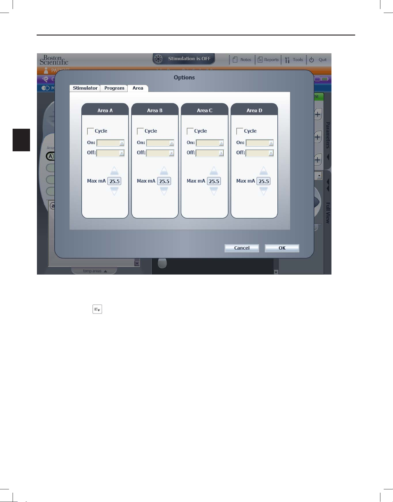
Dening Cycling, Maximum Amplitude, and Ramp Up Time
The Cycle option determines the on and off duration of stimulation delivery. The Maximum Amplitude
option, or Max mA, limits the stimulation amplitude. Cycling and Max mA can be specified for an entire
Program, or for individual Areas within the Program.
Ramp Up is the amount of time to gradually increase stimulation from zero to the programmed
amplitude. Ramp Up time can only be specified for a Program.
Figure 29: Program Options
Bionic Navigator™ 3D Programming Manual
90930923-31 REV A 55 of 309
Page 60
Bionic Navigator™ 3D Programming Manual
en
Figure 30: Area Options
To specify the Cycling for the currently active Program or for a specific Area:
1. Select
next to the Program Name.
2. Select Options.
3. Select either the Program tab or the Area tab, as appropriate.
4. Check the Cycle check box to enable cycling. If you are in the Area tab, check the Cycle
check box for the desired Areas.
5. Choose an ON time and an OFF time from the respective drop-down menus.
6. Select OK.
Bionic Navigator™ 3D Programming Manual
90930923-31 REV A 56 of 309
Page 61

en
To specify the Max mA for the currently active Program or for a specific Area:
Programming the Patient
1. Select
next to the Program Name.
2. Select Options.
3. Select either the Program tab or the Area tab, as appropriate.
4. Adjust the amplitude limit (Max mA) using the up and down arrows. This will be the
maximum amplitude that can be used with the current Program or Area.
5. Select OK.
To specify the Ramp Up for the currently active Program:
1. Select
next to the Program Name.
2. Select Options.
3. Select the Program tab.
4. Check the Ramp Up check box to enable a ramped start.
5. Choose a duration for Ramp Up using the up and down arrows.
6. Select OK.
Specifying Remote Control Locks
The lockout selection provides or denies patient’s access to the following features in the Remote
Control:
• Pulse Width control
• Rate Control
• Main Menu
• Area Menu
• Program Menu
To lock out one of these features in the Remote Control:
1. Select
next to the Program Name.
2. Select Options.
3. Select the Stimulator tab.
4. Check the features you would like to deny access to in the Remote Control. The patient will
only have access to the features that are not checked.
Bionic Navigator™ 3D Programming Manual
90930923-31 REV A 57 of 309
Page 62

Bionic Navigator™ 3D Programming Manual
en
Copying Areas to other Area Slots
The selected Area can be copied to another Area slot within the same program.
Figure 31: Programming Screen
To copy an Area to another Area slot within the same program:
1. Select the desired Program from the Program Carousel.
2. Select the Area you wish to copy.
3. Select the Area Options drop-down list icon
.
4. Choose the Area slot you wish to “Copy” the Area to.
5. After the Area has been copied, the initial source Area will turn off and become inactive. The
new Area will become active and the stimulation state will be the same as the source Area
before the copy, e.g., stimulation will be on if the source Area was on before the copy.
Bionic Navigator™ 3D Programming Manual
90930923-31 REV A 58 of 309
Page 63

en
Clearing an Area
To clear an Area from a Program:
1. Select the desired Program from the Program Carousel.
2. Select the Area you wish to clear.
Programming the Patient
3. Select the Area Options drop-down list icon
.
4. Select Clear.
5. A pop-up message will appear to conrm before clearing the area. Select OK.
Figure 32: Clear Area Dialog Box
Note: If you are clearing the last occupied area, the following message will display:
After clearing this Area, a default Area A will be created. Clear Area?
Temporarily Saving Areas
During programming, there may be a need to temporarily store a specific contact configuration and
stimulation settings for later use. This configuration can later be copied into any Program’s Area slots.
To temporarily save an Area:
1. Select the Area slot that contains the contact conguration and stimulation parameters you
wish to temporarily save.
2. Expand the Temporary Area Expander (“Temp Areas”)
3. Select an empty slot, which will display “Click to save current settings”.
Note: All Temporary Areas will be deleted at the end of the programming session or after changing lead
congurations.
Bionic Navigator™ 3D Programming Manual
90930923-31 REV A 59 of 309
Page 64

Bionic Navigator™ 3D Programming Manual
en
Figure 33: Temporary Areas
To copy a Temporary Area back into one of the Area slots:
1. Select the Area slot you wish to overwrite with a Temporary Area.
2. Select the ↑ icon
3. The following pop-up will appear:
Bionic Navigator™ 3D Programming Manual
90930923-31 REV A 60 of 309
Page 65

en
Figure 34: Overwrite Area Dialog Box
Programming the Patient
4. Select OK.
5. The new Area will initially be inactive with stimulation off.
Completing the Programming Session
After you have created the desired Areas and Programs, you are ready to close your Programming
session. The Areas and Programs you created are saved when you exit the programming screen or if
you select a different program.
To end the programming session:
1. Select the
2. Select from a list of 3 options:
Quit button on the top toolbar.
a. Disconnect from Stimulator: Leaves application open for a new programming
session or to maintain access to reports, and tools.
b. Exit Navigator: Closes the programming application
c. Turn off CP: Powers down the computer
Bionic Navigator™ 3D Programming Manual
90930923-31 REV A 61 of 309
Page 66

Bionic Navigator™ 3D Programming Manual
en
Notes
Select Notes from the top of any screen (while connected to a Stimulator) to display the Notes
pop-up window.
Figure 35: Notes Pop-Up Window
To Enter Notes on the Notes Pop-Up Window:
1. Select a Reason For Visit from the drop-down list at the top of the window.
2. Type notes in the Session Notes text box.
3. Select the Save button.
4. Select the Close button to close the pop-up window.
Note: One entry will be saved for each programming session, and can be edited at any time during the
programming session. Notes from previous sessions can not be modied.
Note: Notes are stored in the CP database. The most recent 245 characters will also be stored in the
Stimulator.
Bionic Navigator™ 3D Programming Manual
90930923-31 REV A 62 of 309
Page 67

Tools
en
Tools
Select Tools from the top of any screen to display the Tools pop-up window. Select the appropriate tab
to access:
• System Defaults
• Backup Data/Logs
• Update Leads.
System Defaults
Figure 36: System Defaults
Bionic Navigator™ 3D Programming Manual
90930923-31 REV A 63 of 309
Page 68

Bionic Navigator™ 3D Programming Manual
en
Component Description
1 Default Pulse Width
Allows you to increase or decrease default value for pulse width
Control
2 Lock access in Remote
Control for new
stimulators
Allows you to specify which parameters can be locked out from
patients on the Remote Control.
NOTE: This is a global, default setting that applies to all newly
congured stimulators. To change this setting for an individual
stimulator, refer to “Specifying Remote Control Locks”.
3 Save Allows you to save changes.
4 Close Closes the window.
Changing the Settings on the Patient Configuration Tab
1. Select the
button to increase the Default Pulse Width or select the button to
decrease the Default Pulse Width.
2. Check the appropriate boxes to lock out patient access from the Remote Control:
• Pulse Width
• Rate
• Main Menu
• Area Menu
• Program Menu
Bionic Navigator™ 3D Programming Manual
90930923-31 REV A 64 of 309
Page 69

en
Backup Data/Logs
This feature allows you to backup the entire patient database on the CP to a specified location.
1. Select Browse to choose a backup location.
2. Select the Save button to perform the backup function.
OR
Select Close to close the window.
Note: After backup is completed, a pop-up window displays which will confirm the location of
the file and indicate that the backup was successful.
Tools
Figure 37: Backup Data/Logs
Bionic Navigator™ 3D Programming Manual
90930923-31 REV A 65 of 309
Page 70

Bionic Navigator™ 3D Programming Manual
en
Update Leads
This feature allows you to enable/disable supported leads within the Lead Selection Panel.
1. Select the row for the desired lead.
2. Type the Key(s) in the Key column.
3. Select Save.
Figure 38: Update Leads (for Clinician programmers upgraded from 9028372-100 software)
Bionic Navigator™ 3D Programming Manual
90930923-31 REV A 66 of 309
Page 71

en
Component Description
Description Lists the available leads:
1x8 percutaneous
1x16 percutaneous
2x8 paddle
New Lead 4 - 4x8 paddle (tightly-spaced)
New Lead 5 - 4x8 paddle (widely-spaced)
Tools
New lead 8
New lead 9
New lead 10
New lead 11
Note:
- 1x8 percutaneous = lead included in the Linear (ST) xxcm 8 Contact Lead kits
or Avista MRI xxcm 8 Contact Lead kits
- 1x16 percutaneous = lead included in the Infinion xxcm 16 Contact Lead kits or
in the Infinion CX xxcm 16 Contact Lead kits
- 2x8 paddle = Artisan xxcm 2x8 Surgical Lead kits
- 4x8 paddle (tightly-spaced) = CoverEdge 32 xxcm 4x8 Surgical Lead kits
- 4x8 paddle (widely-spaced) = CoverEdge X 32 xxcm 4x8 Surgical Lead kits
Note: xx denotes lead length
Note: New leads 8, 9, 10, 11 shown on Figure 38, cannot be activated
Enabled A check mark in this column indicates that the lead is enabled.
Key The column which allows you to type in the Key(s) for each lead.
Save Button Saves your updates.
Close Button Closes the window.
Lead Name Lead Key Code
CoverEdge 32 XXcm 4x8 Surgical Lead Kit OGKIKG
CoverEdge X 32 XXcm 4x8 Surgical Lead Kit GBKFVY
Bionic Navigator™ 3D Programming Manual
90930923-31 REV A 67 of 309
Page 72

Bionic Navigator™ 3D Programming Manual
en
Reports
The Reports option allows you to create, print, and export reports. Select Reports from the top of
any screen to display the Reports pop- up window.
Figure 39: Reports
1. Select the desired information to be included in the report by checking on any of the following
check box(es):
a. Patient Information
b. Clinical Information
c. Conguration Information
d. Stimulation Information
e. Program Use Information
f. Battery Use Information (only for rechargeable batteries)
g. Session Notes History
Bionic Navigator™ 3D Programming Manual
90930923-31 REV A 68 of 309
Page 73

Reports
en
2. You can lter the list of patients based on the date of their last programming session, by
selecting one of the following radio buttons:
a. Today
b. Last 2 Days
c. 1 Week
d. All
3. Select one or more patients to be included in the report.
Note: Select the Clear All button to select all patients listed. Select the Select All button to
select all patients listed.
4. Select Create Report. The Reports Output pop-up window displays.
5. Print or Export the report if desired by selecting the Print or Export button.
6. Select Close to close the report.
Bionic Navigator™ 3D Programming Manual
90930923-31 REV A 69 of 309
Page 74

Bionic Navigator™ 3D Programming Manual
en
Troubleshooting
If you are having difficulty resolving issues, refer to the contact information for Boston Scientific.
Bionic Navigator™ 3D Programming Manual
90930923-31 REV A 70 of 309
Page 75

Glossary
en
Glossary
Ampere
The unit of current intensity (I). In electrical stimulation, current is typically measured in milliamps (mA).
1 mA = 10
–3
(0.001) ampere.
Amplitude
The peak value (in milliamps, mA) of a pulse of stimulation.
Anode
The positive electrode of the implant that produces a positive electrical potential. Current flows from the
anode to the cathode. The selection of anodes and cathodes shapes the stimulation field.
Area
A location of stimulation coverage. Four Areas make up a Program. Areas can be active (available in
the remote control) or inactive (not available in the remote control)
Bionic Navigator 3D Software
Brand name for the Clinician Programmer software.
Burst
See Cycling
Cathode
The negative electrode of the implant that produces a negative electric potential. Current flows from
the anode to the cathode. Stimulation usually occurs near the cathode. The selection of anodes and
cathodes shapes the stimulation field.
Central Point of Stimulation
Center of stimulation field for the electrode combination.
Charger
An external device that is used to charge the implanted Stimulator.
Contact (or electrode)
A component of the lead where current may flow from the IPG’s circuitry to neural tissue.
Charging
The act of recharging the battery, the power source, of the Stimulator.
Clinician Programmer (CP)
The device that runs the programming software.
Bionic Navigator™ 3D Programming Manual
90930923-31 REV A 71 of 309
Page 76

Bionic Navigator™ 3D Programming Manual
en
Cycling (or Burst)
A technique that specifies an ON and OFF duration of stimulation.
Dorsal Cerebrospinal Fluid (dCSF) Space
The thickness of CSF space (or distance) between the dorsal columns of the spinal cord and posterior
dural layer.
Electrical Stimulation
See Stimulation.
Electrode
See Contact.
Electronic Trolling (E-Troll)
An automated programming mode that quickly sweeps the electrode array by moving the cathode in a
bipolar and tripolar fashion. E-Troll mode integrates information from the rostrocaudal positioning of the
leads, the mediolateral positioning of the leads, and approximations from published values for dCSF
thickness, according to the user-defined lead placement.
1,2,3,5,6,7
Explant (or Explantation)
The removal of the implanted SCS System from a patient.
Export
To save a report as an electronic file.
FluoroSync Interface
Clinician Programming Interface that allows the user to 1) drag and drop an electronic representation
of the lead (s) according to their anatomical placement 2) Identify and steer the Central Point of
Stimulation.
Freelink™ Cordless Technology
A term to describe the wireless and cordless set of peripherals designed to provide enhanced convenience
and ease-of-use to patients and physicians. Freelink Cordless Technology includes three key
components: the Remote Control, Charger, and Programming Wand.
Frequency
See Rate.
Grid Lines
One of seven lines on the Lead Placement Panel that allow the user to define the mediolateral
distance between two or more adjacent leads.
programming.
6
8
The CP software uses the mediolateral distance in
Bionic Navigator™ 3D Programming Manual
90930923-31 REV A 72 of 309
Page 77

en
Hertz (Hz)
See Rate.
Glossary
Illumina 3D™ Programming Algorithm
A single term to describe a group of the following terms 1) 3D Stimulation Mapping Technology,
2) LeadSync Technology, 3) SmoothWave™ Technology, and 4) FluoroSync Interface.
Impedance (Ω)
The total opposition offered by a medium (e.g. tissue) to the flow of charged particles (current).
Implant
The Spinal Cord Stimulator System implanted in the patient.
LeadSync Technology
A technology that measures the relative rostrocaudal orientation between two or more leads in the
same Lead Group
4.
Mapping
The process of exploring how different stimulation settings affect where the patient feels stimulation, for
the purpose of creating customized stimulation programs.
Microseconds (μs)
One millionth of a second (10-6 s).
Navigate
An automated programming mode that uses multiple electrode combinations to fine tune and optimize
stimulation coverage with high resolution. Navigate mode integrates information from the rostrocaudal
positioning of the leads, the mediolateral positioning of the leads, and approximations from published
values for dCSF thickness, according to the user-defined lead placement.
1,2,3,5,6,7
Prism Targeting Technology
Prism Targeting Technology utilizes multiple independent current control (MICC) to better focus the
stimulation field of the primary cathode, either laterally or rostrocaudally. Prism targeting involves
anode intensification programming that distributes current from the primary cathode to the IPG, thereby
increasing the relative strength of “guarding” anodes.
Program
A stimulation configuration consisting of up to four independent pain coverage areas.
Program Database
A list of Programs that were once saved in the Stimulator (i.e., program history).
Bionic Navigator™ 3D Programming Manual
90930923-31 REV A 73 of 309
Page 78

Bionic Navigator™ 3D Programming Manual
en
Pulse Rate
See Rate.
Pulse Width
The time duration of a pulse of current, measured in microseconds (μs).
Ramp Up Time or Ramp Time
The amount of time the Stimulator will take to increase stimulation from 0 mA to the programmed
amplitude.
Rate (or Frequency or Pulse Rate)
The number of pulses (or bursts) of electric current delivered in one second, measured in Hertz (Hz).
Remote Control
A handheld device patients use to control their stimulation therapy.
Serial Number
A number that uniquely identifies a device.
SmoothWave Technology
Multiple Independent Current Control
Stimulation (or Electrical Stimulation)
Application of small doses of current to neural tissue via electrodes.
3D Stimulation Mapping Technology
A capability incorporated in the E-troll and Navigate programming modes that integrates 3 dimensions
of lead position information which include rostrocaudal positioning of the leads, mediolateral positioning
of the leads and approximations of the thickness of the dorsal cerebrospinal fluid (dCSF) space from
published values, according to user defined lead placement.
Vertebral Level
A vertebrae of the vertebral column, such as T7, T8, or L3. Each vertebral level in the Lead Placement
Panel is associated with an approximation of the dorsal cerebrospinal fluid (dCSF) thickness at that
5
level.
Voltage
The CP software uses published dCSF thickness measurements.
A measure of electrical potential.
Bionic Navigator™ 3D Programming Manual
90930923-31 REV A 74 of 309
Page 79

References
en
References
1
Holsheimer J, Wesselink WA. Optimum electrode geometry for spinal cord stimulation: the narrow bipole and tripole. Med Biol Eng Comput 1997;
35:493-497.
2
Holsheimer J, Wesselink WA. Effect of anode-cathode configuration on paresthesia coverage in spinal cord stimulation. Neurosurgery 1997; 41:654-9;
discussion 659-60.
3
Lee D, Hershey B, Bradley K, Yearwood T. Predicted effects of pulse width programming in spinal cord stimulation: a mathematical modeling study. Med
Biol Eng Comput 2011; 49:765-774.
4
Moffitt, M.A., Lee, D.C., Bradley, Kerry. Spinal Cord Stimulation: Engineering Approaches to Clinical and Physiological Challenges. In: Zhou DD,
Greenbaum E, editors. Implantable Neural Prostheses 1: Devices and Applications. New York: Springer; 2009. p.155-94.
5
Holsheimer J, Barolat G. Spinal Geometry and Paresthesia Coverage in Spinal Cord Stimulation. Neuromodulation 1998;1:129-136.
6
Lee D, Zhu C, Bradley K, Peterson D, Moffitt M. PRiMA programming: Patient-specific Real-Time Model-based Algorithm Using Virtual Contacts for
Precise Neural Targeting. North America Neuromodulation Society, Dec8-11, 2011, Las Vegas.
7
Zhu C, Lee D, Bradley K. ‘Smooth Steering’: Dynamic Volume of Activation Changes and Adaptive Amplitude Compensation during Spinal Cord
Stimulation Programming. North America Neuromodulation Society, Dec8-11, 2011, Las Vegas.
8
Lee D, Moffitt M, Bradley K, Peterson D. I-Sculpting technique to correct electric field distortion by percutaneous lead placement offset or A measure of
electrical potential migration. North America Neuromodulation Society, Dec 8-13, 2007 Acapulco, Mexico.
Bionic Navigator™ 3D Programming Manual
90930923-31 REV A 75 of 309
Page 80

Manuel de programmation 3D Bionic Navigator™
fr
Garanties
Boston Scientic Corporation se réserve le droit de modier, sans préavis, les informations
relatives à ses produits dans le but d’améliorer leur abilité ou leur capacité de fonctionnement.
Marques commerciales
Toutes les marques commerciales citées appartiennent à leurs détenteurs respectifs.
Informations complémentaires
Pour les indications et autres informations associées, voir les Indications DFU. Se reporter
aux contre-indications, aux avertissements, aux précautions, à la synthèse des événements
adverses, aux instructions du médecin, aux informations sur la mise au rebut des composants
et aux coordonnées de Boston Scientic dans Information for Prescribers DFU pour votre
système de stimulation de la colonne vertébrale. Pour toute autre information relative à cet
appareil et non incluse dans le présent manuel, et pour les symboles d’étiquetage et détails
des garanties, se reporter au programme utilitaire de chier de données (DFU) répertorié dans
votre Guide de référence.
Numéros de modèles des produits
Numéro de modèle Description
NM-7153-11A Programmateur clinicien
NM-7153-11AR Programmateur clinicien
(reconditionné)
NM-7153-30* Programmateur clinicien
NM-7153-30R* Programmateur clinicien
(reconditionné)
*Applicable après l'installation de la version logicielle 9028372-110.
Manuel de programmation 3D Bionic Navigator™
90930923-31 REV A 76 sur 309
Page 81

Table des matières
fr
Table des matières
Introduction ............................................................................................................79
Paramétrage ............................................................................................................ 80
Raccordez la télécommande de programmation au Programmateur clinicien ................................81
Débuter une session .............................................................................................. 82
Écran principal .................................................................................................................................82
Saisir des informations sur le patient. ..............................................................................................85
Changer de patient ..........................................................................................................................87
Dénir la douleur du patient ............................................................................................................88
Congurer le Programmateur clinicien et le stimulateur ................................... 90
Se connecter à un stimulateur .........................................................................................................90
Affectation d’un patient à un stimulateur ..........................................................................................94
Choisir le dossier du patient à utiliser ..............................................................................................95
Dissocier un patient .........................................................................................................................96
Consulter l’état de la connexion de programmation .........................................................................96
Afcher les informations relatives au Programmateur clinicien et à la télécommande de
programmation .................................................................................................................................97
Congurer les sondes ......................................................................................................................99
Modier l’orientation d’une sonde dans le volet de positionnement des sondes ...........................104
Affecter une sonde à un groupe .....................................................................................................105
Utilisation de la technologie LeadSync™ .......................................................................................106
Mesurer les impédances ................................................................................................................ 111
Programmer le patient ......................................................................................... 113
Paramètres programmable de Precision Spectra .........................................................................113
Amplitude d'intensité maximale par électrode en fonction de l'impédance
(pour toutes les sondes autres que la sonde chirurgicale 4x8) ......................................................114
Amplitude d'intensité maximale par électrode en fonction de l'impédance
(pour la sonde chirurgicale 4x8) .....................................................................................................114
Amplitude maximale en fonction de la fréquence et de la largeur d'impulsion
(pour toutes les sondes autres que la sonde chirurgicale 4x8) ......................................................115
Amplitude maximale en fonction de la fréquence et de la largeur d'impulsion
(pour la sonde chirurgicale 4x8) .....................................................................................................115
Paramètres programmables des systèmes Precision Novi et Precision Montage MRI .................116
Amplitude maximale du courant par électrode par rapport à l'impédance .................................... 116
Amplitude maximale basée sur la fréquence et la largeur d'impulsion .......................................... 117
Écran Schématiser et programmes ...............................................................................................118
Présentation ................................................................................................................................... 118
Manuel de programmation 3D Bionic Navigator™
90930923-31 REV A 77 sur 309
Page 82

Manuel de programmation 3D Bionic Navigator™
fr
Volet de base ................................................................................................................................. 119
Volet des paramètres .....................................................................................................................120
Onglet Vue intégrale ......................................................................................................................122
Sélectionner le programme ............................................................................................................123
Programmer les électrodes ............................................................................................................124
Utiliser le mode E-Troll ...................................................................................................................125
Utiliser le mode Navigation ...........................................................................................................125
Utiliser le mode Manuel ................................................................................................................126
Augmenter/Diminuer l’amplitude ....................................................................................................126
Augmenter/Diminuer la largeur d’impulsion ...................................................................................127
Augmenter/Diminuer la fréquence .................................................................................................127
Utiliser les raccourcis clavier ..........................................................................................................128
Comprendre les emplacements de zone .......................................................................................128
Activer ou désactiver la stimulation ................................................................................................129
Comprendre les options avancées ................................................................................................131
Comprendre les options du programme ........................................................................................132
Dénir les options Cycle, Amplitude maximale, et Durée de montée ............................................133
Dénir les verrouillages de la télécommande ................................................................................135
Copier des zones vers d’autres emplacements de zones .............................................................136
Effacer une zone ............................................................................................................................137
Enregistrement temporaire des zones ...........................................................................................137
Terminer la séance de programmation ..........................................................................................139
Notes .....................................................................................................................140
Outils .....................................................................................................................141
Valeurs par défaut du système ......................................................................................................141
Données/journaux de sauvegarde .................................................................................................143
Actualiser les sondes .....................................................................................................................144
Rapports ................................................................................................................ 146
Dépannage ............................................................................................................ 148
Glossaire ............................................................................................................... 149
Références ............................................................................................................ 153
Manuel de programmation 3D Bionic Navigator™
90930923-31 REV A 78 sur 309
Page 83

Introduction
fr
Introduction
Bienvenue au programmateur clinicien Bionic Navigator™ 3D de Boston Scientific. Votre logiciel
Programmateur clinicien (PC) vous permet de définir et d’ajuster des paramètres de stimulation pour le
système de stimulation médullaire. L’objectif du présent manuel de programmation est de fournir des
informations et des instructions utiles aux utilisateurs du Programmateur clinicien.
L’interface utilisateur a été conçue pour vous permettre d’y naviguer avec autant de facilité que
possible. Une séance de programmation type se compose des procédures séquentielles suivantes :
Créer un profil pour le patient
↓
Se connecter au stimulateur
↓
Brancher et configurer les sondes
↓
Schématiser et enregistrer les programmes de stimulation
Les pages qui suivent vont vous décrire des concepts de base qui vous permettront de réaliser les
procédures susmentionnées ainsi que d’autres fonctions telles que la création de rapports.
En cas de problème, reportez-vous à la section Dépannage.
REMARQUE : les écrans illustrés dans ce manuel peuvent légèrement différer des écrans qui
apparaissent dans le programmateur clinicien de votre système Bionic Navigator 3D.
Manuel de programmation 3D Bionic Navigator™
90930923-31 REV A 79 sur 309
Page 84

Manuel de programmation 3D Bionic Navigator™
fr
Paramétrage
Figure 1 : Logiciel Programmateur clinicien et télécommande de programmation
Le Programmateur clinicien communique avec le stimulateur par l’intermédiaire d’une télécommande
de programmation. La télécommande de programmation utilise une liaison de radio fréquences (RF)
pour communiquer avec le stimulateur. Il est possible de créer et de télécharger des programmes sur le
Programmateur clinicien afin de voir un aperçu, d’activer et de modifier des paramètres de stimulation.
Les programmes de stimulation peuvent également être enregistrés sur le stimulateur.
AVERTISSEMENT : utilisez seulement les composants des systèmes Precision Spectra™,
Precision Novi™ et Precision Montage™ MRI de votre système de stimulation médullaire de
Boston Scientic avec le système Bionic Navigator 3D. Dans le cas contraire, vous pourriez ne
plus réussir à programmer le stimulateur.
Manuel de programmation 3D Bionic Navigator™
90930923-31 REV A 80 sur 309
Page 85

Paramétrage
fr
AVERTISSEMENT : Le Programmateur clinicien n’est pas un équipement pour l’environnement
du patient tel que déni par la norme CEI 60601-1. Le Programmateur clinicien et la personne
qui l’utilise ne doivent pas être en contact avec le patient pendant la programmation.
Remarque : Consultez les manuels ASUS Eee Slate B121 sur www.asus.com pour des instructions
supplémentaires. Si vous le souhaitez, un moniteur externe peut être connecté pour une meilleure
visualisation par plusieurs personnes. Pour les ordinateurs ASUS, insérez un câble mini HDMI dans le
port pour connecter une interface multimédia haute dénition (HDMI).
Raccordez la télécommande de programmation au Programmateur clinicien
1. Insérez le port USB Mini-B du câble de raccordement USB au port USB Mini-B situé sur le
côté de la télécommande de programmation.
2. Insérez l’extrémité Standard-A du câble de raccordement USB au port USB Standard-A du
Programmateur clinicien.
Manuel de programmation 3D Bionic Navigator™
90930923-31 REV A 81 sur 309
Page 86

Manuel de programmation 3D Bionic Navigator™
fr
Débuter une session
Allumez [ON] le Programmateur clinicien pour afficher le bureau Neuromodulation. Sélectionnez
l’icône
pour lancer le logiciel Bionic Navigator 3D. Lors du lancement, l’écran principal s’affiche.
Pour revenir à l’écran principal à tout moment, sélectionnez tout espace accessible depuis la barre
d’extension grise de l’écran principal située en haut de l’écran.
Écran principal
Figure 2 : Écran principal
Les composants de l’écran principal sont généraux (c’est-à-dire qu’ils sont présents sur tous les
écrans) et sont décrits dans le tableau 1.
Manuel de programmation 3D Bionic Navigator™
90930923-31 REV A 82 sur 309
Page 87

fr
Tableau 1 : composants généraux
Composant Description
Débuter une session
1. Barre d'extension
du patient
2. Configuration de la
barre d'extension
Affiche le nom du patient actuel ainsi que son échelle de douleur.
Sélectionnez la barre d'extension du patient pour afficher l'écran
Infos patient qui vous permet de :
• Créer un nouveau prol de patient
• Saisir/Modier les informations du patient
• Enregistrer l'échelle de douleur du patient
Sélectionnez la barre d'extension Configuration pour afficher l'écran
de configuration qui vous permet de :
• Vous connecter à un stimulateur
• Dénir les congurations des sondes
• Vérier les impédances
L'état de connexion du Programmateur clinicien est également
indiqué à droite de cette barre d'extension. La couleur verte indique
la présence d'une connexion, tandis qu'un X rouge indique que la
connexion n'a pas été établie.
3. Barre d'extension
Schématiser et
programmes
Sélectionnez la barre d'extension Schématiser et programmes
pour afficher l'écran Schématiser et programmes qui vous permet de
paramétrer et de configurer des programmes de stimulation.
Manuel de programmation 3D Bionic Navigator™
90930923-31 REV A 83 sur 309
Page 88

Manuel de programmation 3D Bionic Navigator™
fr
4. Bouton Stimulation
activée/désactivée
Le bouton Stimulation activée/désactivée est affiché en haut
de chaque écran et change de couleur pour indiquer l'état de la
connexion ainsi que le statut de la stimulation activée/désactivée :
Le Programmateur clinicien n'est pas connecté à un stimulateur.
Le Programmateur clinicien est connecté à un stimulateur, et la
stimulation est désactivée.
Le Programmateur clinicien est connecté à un stimulateur, et la
stimulation est activée.
Lorsque le Programmateur clinicien est connecté à un stimulateur,
vous pouvez activer et désactiver la stimulation à tout moment en
sélectionnant le bouton Stimulation activée/désactivée.
5.
6.
7.
8.
Remarques
Rapports
Outils
Quitter
Affiche la fenêtre contextuelle Remarques qui vous permet de :
• Sélectionner le motif d'une visite.
• Enregistrer des remarques sur une séance.
• Consulter l'historique des remarques.
Affiche la fenêtre contextuelle Rapports qui vous permet de générer et
d'imprimer des rapports pouvant être personnalisés.
Affiche la fenêtre contextuelle Outils qui vous permet de :
• Augmenter ou diminuer la valeur par défaut de la durée et de la
fréquence d'impulsion.
• Préciser les paramètres qui ne sont pas disponibles sur la
télécommande.
• Sauvegarder des données et des journaux.
• Activer ou désactiver des sondes.
Affiche la fenêtre contextuelle Quitter qui vous permet de :
• Vous déconnecter du stimulateur.
• Quitter le logiciel Programmateur clinicien.
• Éteindre le Programmateur clinicien.
Manuel de programmation 3D Bionic Navigator™
90930923-31 REV A 84 sur 309
Page 89

Débuter une session
fr
Saisir des informations sur le patient.
Depuis l’écran principal, sélectionnez la barre d’extension Patient pour accéder à l’écran Informations
patient (par défaut) et à l’écran Échelle de douleur.
Figure 3 : Écran Informations patient
Remarque : les champs obligatoires dans l’écran ci-dessus sont indiqués par un astérisque.
Les boutons Informations patient
et Échelle de douleur situés à gauche de l’écran
Patient vous permettent de basculer entre l’écran Informations patient et l’écran Échelle de douleur.
Consultez la section « Définir l’échelle de douleur d’un patient » pour de plus amples informations.
Pour saisir/modifier des informations dans l’écran Patient (Informations) :
1. Saisissez l’Identiant du patient/du dossier (facultatif)
2. Saisissez le Nom de famille du patient.
3. Saisissez le Prénom du patient.
Manuel de programmation 3D Bionic Navigator™
90930923-31 REV A 85 sur 309
Page 90

Manuel de programmation 3D Bionic Navigator™
fr
4. Sélectionnez l’icône du calendrier appropriée pour sélectionner sa Date de naissance.
Conseil : pour modier rapidement l’année de naissance, cliquez ou tapez deux fois sur
[Mois, Année] en haut du calendrier pour pouvoir parcourir (de gauche à droite) différentes
décennies.
5. Saisissez le Sexe du patient : (Facultatif)
a. Femme
b. Homme
6. Saisissez l’Adresse du patient. (Facultatif)
7. Saisissez le nom du Médecin ou sélectionnez-le dans la liste déroulante. (Facultatif)
Remarque : cette zone de texte n’est activée que lorsque le Programmateur clinicien est
connecté à un stimulateur. Reportez-vous à la section Se connecter à un stimulateur de ce
manuel.
8. Saisissez le Diagnostic ou sélectionnez-le dans la liste déroulante (Facultatif)
Remarque : cette zone de texte n’est activée que lorsque le Programmateur clinicien est
connecté à un stimulateur. Reportez-vous à la section Se connecter à un stimulateur de ce
manuel.
9. Sélectionnez le bouton Enregistrer pour enregistrer les informations saisies.
Important : les modications apportées hors ligne ne seront enregistrées que sur le
Programmateur clinicien.
Remarque : vous pouvez revenir à la dernière version enregistrée des informations du patient
en sélectionnant le bouton Revenir dans l’écran Patient (Informations).
Remarque : pour créer un nouveau dossier de patient, sélectionnez le bouton Créer nouveau
patient et répétez les étapes 1 à 9 le cas échéant.
Manuel de programmation 3D Bionic Navigator™
90930923-31 REV A 86 sur 309
Page 91

Débuter une session
fr
Changer de patient
Vous pouvez choisir d’afficher les informations d’un autre patient, lorsque le Programmateur clinicien
n’est pas connecté à un stimulateur, en sélectionnant le bouton Changer de patient dans l’écran
Informations patient. La fenêtre contextuelle Sélectionner un patient s’affiche alors :
Figure 4 : Fenêtre contextuelle Sélectionner un patient
Remarque : utilisez les barres de délement situées en bas et sur le côté de la fenêtre contextuelle
pour consulter toutes les informations disponibles.
Pour changer de patient :
1. Saisissez une partie du nom du patient dans la zone de texte Rechercher pour restreindre
la liste.
2. Sélectionnez le nom du patient dans la liste.
3. Sélectionnez le bouton Affecter un patient.
Manuel de programmation 3D Bionic Navigator™
90930923-31 REV A 87 sur 309
Page 92

Manuel de programmation 3D Bionic Navigator™
fr
Dénir la douleur du patient
Depuis l’écran Informations patient, sélectionnez le bouton Échelle de douleur pour afficher
l’écran Échelle de douleur.
Remarque : un stimulateur doit être connecté au Programmateur clinicien pour pouvoir accéder
à l’écran Échelle de douleur. Reportez-vous à la section « Se connecter à un stimulateur ».
Figure 5 : Écran Échelle de douleur
Remarque : comme indiqué sur l’écran Échelle de douleur dans Figure 5, 0 représente Aucune
douleur et 10 représente la Pire douleur imaginable.
Manuel de programmation 3D Bionic Navigator™
90930923-31 REV A 88 sur 309
Page 93

fr
Pour saisir l’échelle de douleur d’un patient :
1. Sélectionnez le bouton numérique coulissant dans la barre Stimulation activée et faites-le
glisser sur le numéro qui représente au mieux le degré de douleur du patient lorsque la
stimulation est activée.
2. Sélectionnez le bouton numérique coulissant dans la barre Stimulation désactivée et
faites-le glisser sur le numéro qui représente au mieux le degré de douleur du patient
lorsque la stimulation est désactivée.
Remarque : la stimulation peut être activée et désactivée à tout moment, en sélectionnant le
bouton Stimulation activée/désactivée en haut de l’écran.
Débuter une session
Manuel de programmation 3D Bionic Navigator™
90930923-31 REV A 89 sur 309
Page 94

Manuel de programmation 3D Bionic Navigator™
fr
Congurer le Programmateur clinicien et le stimulateur
L’écran Configuration vous permet de paramétrer le Programmateur clinicien et le stimulateur en vue
de la programmation. Dans l’écran Configuration, vous pouvez :
• Établir une liaison de programmation entre le Programmateur clinicien et le stimulateur ;
• Vérier l’état de la connexion de programmation ;
• Identier les sondes utilisées et enregistrer leur implantation ;
• Paramétrer la connexion entre les sondes et les ports du stimulateur ;
• Exécuter LeadSync™ pour identier et appliquer le décalage relatif des sondes ;
• Contrôler les impédances de chaque contact.
Se connecter à un stimulateur
Pour programmer un stimulateur, vous devez connecter le Programmateur clinicien à ce stimulateur.
1. Sélectionnez la barre d’extension Conguration pour afcher l’écran Connecter.
2. Sélectionnez le bouton pour établir une liaison de programmation entre le
stimulateur souhaité et le Programmateur clinicien. L’indicateur d’état de la connexion
s’afche en vert lorsqu’une connexion valide est établie.
Remarque : après avoir connecté le stimulateur souhaité et le Programmateur clinicien, une
télécommande (et dans le cas d’un SEE, le bouton SEE activé/désactivé) peut être utilisée pour
modier les paramètres du stimulateur (par ex., activer ou désactiver la stimulation). Toute modication
ultérieure du stimulateur effectuée à partir du Programmateur clinicien transférera au stimulateur les
paramètres afchés sur le Programmateur clinicien.
Avertissement : dans le cas de l’utilisation de la télécommande pour arrêter la stimulation
pendant la programmation, désactivez le bouton Stimulation activée/désactivée sur le
Programmateur clinicien avant de reprendre la programmation. Cela permettra d’assurer la
synchronisation du Programmateur clinicien avec l’état de stimulation du stimulateur.
Manuel de programmation 3D Bionic Navigator™
90930923-31 REV A 90 sur 309
Page 95

Congurer le Programmateur clinicien et le stimulateur
fr
Figure 6 : Écran de connexion
Composant Description
1. Connexion entre
le Programmateur
Affiche l'état des connexions entre le Programmateur clinicien, la
télécommande et le stimulateur.
clinicien, la
télécommande et le
stimulateur
2. Bouton Ré-analyser Sélectionnez ce bouton pour ré-analyser les environs à la recherche
de stimulateurs disponibles. (Désactivé si le Programmateur clinicien
est déjà connecté à un stimulateur)
Manuel de programmation 3D Bionic Navigator™
90930923-31 REV A 91 sur 309
Page 96

Manuel de programmation 3D Bionic Navigator™
fr
3. Informations sur le
stimulateur
Remarque : lorsque
vous accédez à
l'écran Connecter
pour la première fois,
le Programmateur
clinicien analyse
les environs pour
localiser et répertorier
tous les stimulateurs
Affiche les informations suivantes :
• Type de stimulateur (stimulateur d'essai ou générateur
d'impulsions implantable)
• Numéro de modèle
• Numéro de série
• Version du micrologiciel
• Informations sur la durée de vie du stimulateur, si dans la période
de Fin de vie de la batterie ou ERI (Indicateur de Remplacement
Électif) pour les stimulateurs non rechargeables ou dans les
6 mois de la date planiée de n de durée de vie de tous les
stimulateurs.
disponibles.
4. Informations relatives
au patient
Nom, Prénom et Date de naissance sont affichés si le stimulateur
est affecté à un patient. Dans le cas contraire, ces champs sont
vides. Consultez « Affectation d'un patient à un stimulateur ».
5. Bouton Dissocier Sélectionnez ce bouton pour dissocier le patient affiché du
6. Indicateur de l'état de
connexion
7. Bouton Connecter ou
Déconnecter
stimulateur connecté.
L'indicateur affiche un cercle vert si le stimulateur est connecté au
Programmateur clinicien.
Lorsqu'aucun stimulateur n'est connecté, ce bouton indique
« Connecter ». Lorsqu'un stimulateur est connecté, ce bouton
indique « Déconnecter ».
Sélectionnez ce bouton pour Connecter ou Déconnecter le
stimulateur souhaité.
Manuel de programmation 3D Bionic Navigator™
90930923-31 REV A 92 sur 309
Page 97

Congurer le Programmateur clinicien et le stimulateur
fr
Figure 7 : Écran Connexion une fois que le stimulateur d’essai est connecté
Manuel de programmation 3D Bionic Navigator™
90930923-31 REV A 93 sur 309
Page 98

Manuel de programmation 3D Bionic Navigator™
fr
Affectation d’un patient à un stimulateur
Un profil de patient doit être associé à un stimulateur avant qu’un stimulateur ne puisse être
programmé. Si un stimulateur n’est pas affecté à un profil de patient, le logiciel vous invite à affecter un
profil de patient depuis la base de données des profils de patients du Programmateur clinicien.
Figure 8 : Boîte de dialogue Changer de patient
1. Si vous le souhaitez, saisissez le prénom, le nom de famille ou l’identiant du patient/du
dossier dans la zone de texte Rechercher an de ltrer la liste des patients.
2. Sélectionnez le patient approprié.
3. Sélectionnez le bouton Affecter un patient.
Manuel de programmation 3D Bionic Navigator™
90930923-31 REV A 94 sur 309
Page 99

Congurer le Programmateur clinicien et le stimulateur
fr
Choisir le dossier du patient à utiliser
Au cours de la procédure de connexion, si les informations patient du stimulateur et les informations
patient de la base de données du Programmateur clinicien diffèrent, vous serez invité à sélectionner le
dossier patient à utiliser.
Figure 9 : Boîte de dialogue Changer de dossier patient
1. Consulter les dossiers des patients.
2. Sélectionnez le bouton Utiliser ce dossier en regard du dossier que vous souhaitez
enregistrer sur le stimulateur et le Programmateur clinicien. Le dossier non sélectionné sera
remplacé.
Manuel de programmation 3D Bionic Navigator™
90930923-31 REV A 95 sur 309
Page 100

Manuel de programmation 3D Bionic Navigator™
fr
Dissocier un patient
Vous pouvez dissocier ou supprimer un profil patient d’un stimulateur.
Remarque : le bouton Dissocier ne s’affiche que dans l’écran Connecter Configuration lorsqu’un profil
de patient est affecté à un stimulateur.
Depuis l’écran Connecter :
1. Sélectionnez le bouton
pour le stimulateur auquel le patient est
actuellement associé.
2. Le prol du patient est supprimé du stimulateur et la connexion de programmation entre le
Programmateur clinicien et le stimulateur est désactivée. Pour le SEE, toutes les données
de programmation, utilisation et conguration de sonde sont également supprimées.
Consulter l’état de la connexion de programmation
L’état de la connexion de programmation entre le Programmateur clinicien, la télécommande de
programmation et le stimulateur s’affiche sur l’écran Connecter.
Figure 10 : État connecté
Figure 11 :
Manuel de programmation 3D Bionic Navigator™
90930923-31 REV A 96 sur 309
État déconnecté
 Loading...