

Page 1

VRS Micro
Micro Reference Diffuse-Field
Surround Speaker System
Page 2

2
Specifications
Frequency Response (±3dB) 120–20,000Hz
Recommended Amplifier Power 15–100 watts
Nominal Impedance 8 ohms
Sensitivity [1 watt (2.83v) at 1m] 86dB
Full-Range Driver 31⁄2" (89mm) copolymer
High-Frequency Driver 21⁄2" (65mm) polymer-treated paper
Crossover Frequency 350Hz
Dimensions (HxWxD) 75⁄8 x 37⁄8 x 53⁄8" (194 x 98 x 137mm)
Weight/each 4 lbs (2kg)
Finish Black or white
Description
The VRS Micro is a diffuse-field surround
speaker that provides realistic rear channel
surround effects with Dolby
®
ProLogic®and
Dolby
®
Digital decoding electronics.
The VRS Micro cabinet is sculptured to aim
sound along the walls, rather than directly at
the listener, and to blend with the room’s decor.
Frequencies from 120 to 20,000Hz are handled by a specially designed 3
1
⁄2" (89mm) fullrange driver, firing toward the front of the
room. Frequencies above 350Hz are handled
by a 2
1
⁄2" (65mm) high-frequency driver, firing
backward. Gold-plated five-way binding posts
allow the connection of virtually any speaker
cable. Straightforward mounting of the speaker on any wall or ceiling can be easily accomplished with the included brackets.
Page 3
3
Diffuse Sound
In a movie theater, a diffuse surround sound
field is created by using an array of surround
speakers around the sides and rear of the
theater. Since this is not practical in the home,
a diffuse-field speaker achieves the same effect
with a single pair of speakers.
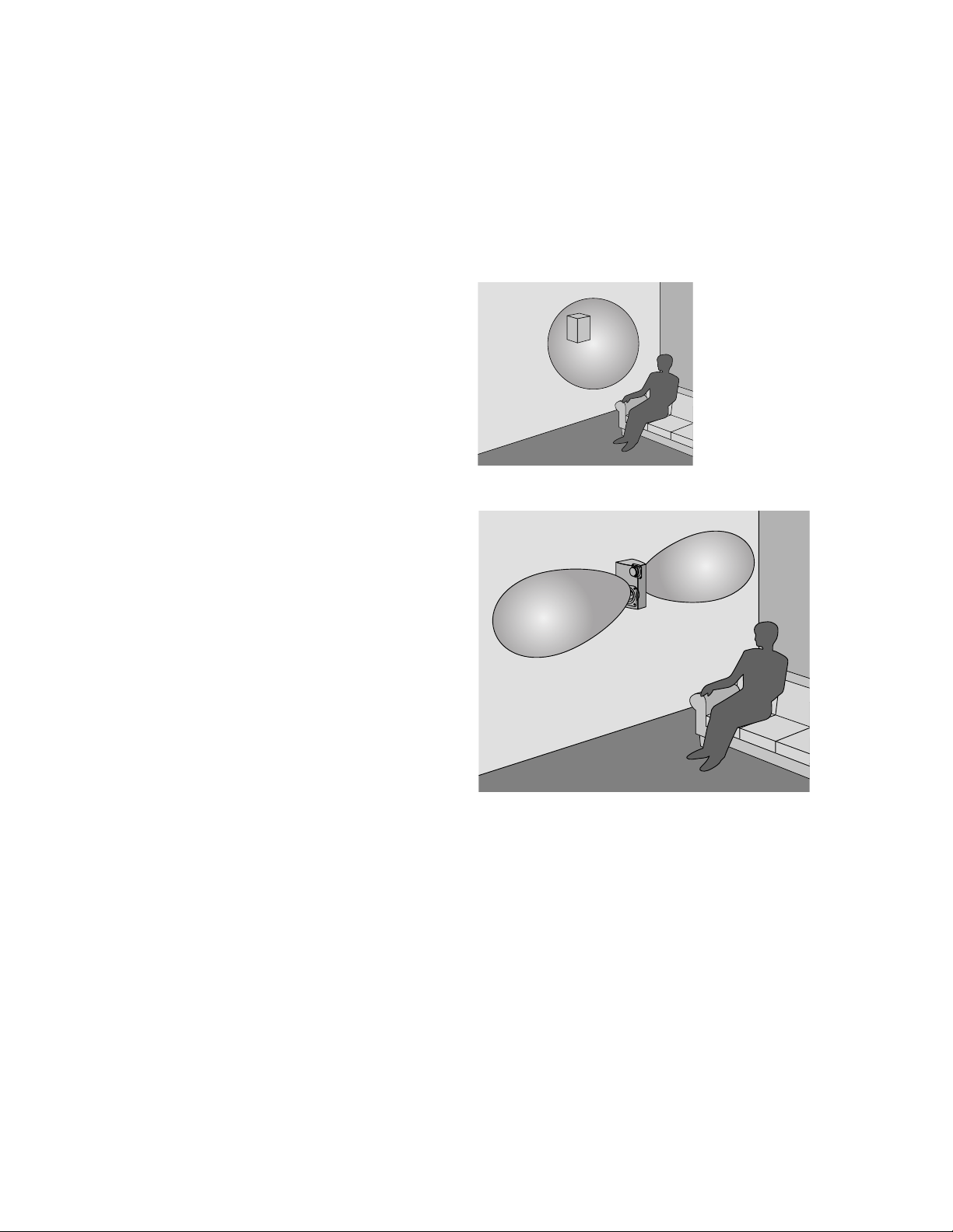
When a conventional direct-radiating speaker
is used for surround, sound is aimed directly at
the listener. Because the listener can localize
the sound, the surround effect is dramatically
reduced (above right).
The VRS Micro contains two drivers, operating
with opposite polarities—one speaker pushes
out and the other pulls in. This directs most of
the sound sideways (right). The VRS Micro generates a “figure 8” pattern above 350Hz along
the walls of the room. The sound is then reflected from the end walls, ceiling and floor before
returning to the listener as diffuse sound, which
comes from all around the listener.
Page 4

4
Connecting Your VRS Micro Speakers
Connect the speaker’s terminals to those on the amplifier or receiver designated for “surround” or
“rear channel effects.” Maintain consistency of the + (red) and – (black) connections by using the
markings on the wire.
We recommend 18-gauge (or heavier) speaker wire for runs up to 25' (8m), and thicker 16-gauge
speaker wire for longer runs. Strip
1
⁄2" (12mm) of insulation from the ends of each wire to expose
the conductors. Tightly twist the wire strands together. Maintain the consistency of the + (red) and
– (black) connections.
IMPORTANT: Typically, one side of the hook-up wire is ribbed and the
other is smooth. Connect the ribbed side to the + (red) terminals and
the smooth side to the – (black) terminals.
WARNING: To prevent electrical shock, always switch off the amplifier
or receiver when making connections to the speaker.
Using the five-way binding posts: The binding posts permit easy connection to banana plugs, pins, spade lugs and bare wire. The metal surfaces are plated with 24K gold to resist corrosion.
Receiver or amplifier
Left speaker
Center speaker
Front channel
RightCenterLeft
Right speaker
Rear channel
Left
Left VRS Micro Right VRS Micro
Right
Page 5

5
Room Placement
Room placement is one of the most important factors contributing to the quality of home theater
sound. Take a few minutes to place your speakers correctly to ensure they will sound their best.
If the viewing area is in a corner, the speakers may be
placed to either side on adjacent walls.
One or both of the VRS Micro speakers may be hung from
the ceiling. Make sure the arrow on the rear label points to
the front of the room.
If the listening position is against the wall, place the
speakers to either side, no less than 20" (50cm) from the
rear wall.
Place the VRS Micro speakers on either side of the
listening area.
IMPORTANT: Your speakers have been packed as a LEFT and RIGHT matched set. Make sure that each speaker is mounted
on the correct side, with the larger driver pointing to the front of the theater area. The arrow on the back of each speaker
should point toward the front of the room.
Page 6

6
Listening Levels and Power-Handling
IMPORTANT: Adjusting Listening Volume–To obtain the best home theater effect, balance the
sound level of each speaker. Home theater systems contain a test signal that simplifies this procedure. Refer to the instructions provided with your surround sound electronics.
The power recommendation for the speaker assumes the amplifier is not overdriven, which, over a
long period, can damage even our rugged speakers. If you hear a harsh, gritty noise, turn down the
volume control. Prolonged or repeated operation with a distorted signal from the amplifier can
cause damage to the speakers, which is not covered by the warranty.
Setting Up Your Home Theater System
Volume Levels: To obtain the best home theater effect, match the sound levels of each speaker.
Home theater systems include a test signal that simplifies this level matching. Refer to the instructions provided with your surround sound electronics.
Surround Channel Mode: If your electronics have a surround channel mode, it should be set
to “Normal” or “Small.” This setting will divert any low bass in the surround channels to the
subwoofer.
Wall- or Ceiling-Mounting Your VRS Micro Speakers
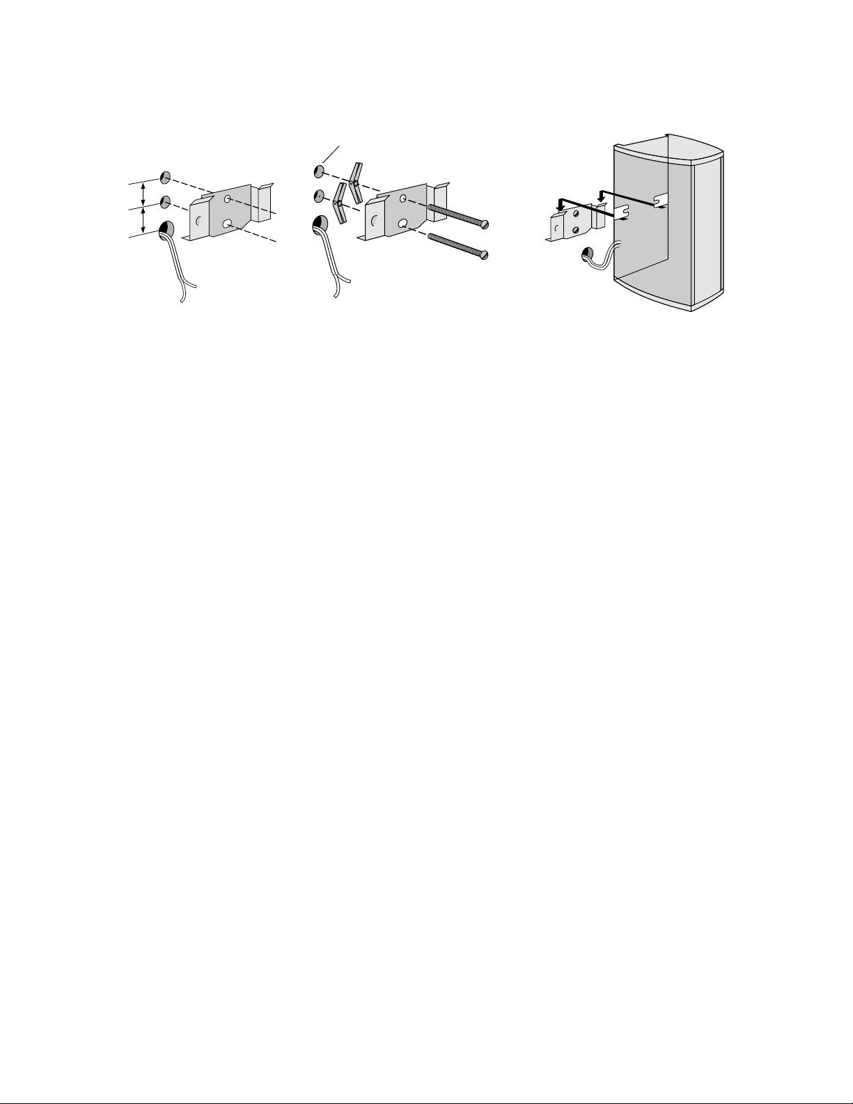
The VRS Micro is designed to be mounted directly onto a wall or ceiling. Attach the supplied
bracket to the wall or ceiling and clip the speaker to the bracket.
You may run wires to the speakers on the wall surface or behind the wall. Use the recessed area on
the back of the speaker to accommodate the wire slack.
Mounting on drywall, paneling or other hollow surfaces: Use the 6-32 x 2" machine screws and
toggle wings provided. The toggle wings require a
1
⁄2" (12mm) hole.
Mounting on wood and other solid surfaces: Use a #6 or #8 wood screw.
Mounting on masonry, adobe and similar surfaces: Consult a knowledgeable installer about
proper hardware. You will obtain best results with #6 or #8 screws.
IMPORTANT: Your speakers have been packed as a LEFT and RIGHT matched set. Make sure that
each speaker is mounted on the correct side, with the larger driver pointing toward the front of the
theater area. The arrow on the back of each speaker should point toward the front.
Page 7
7
Painting Your VRS Micro Speakers
You may paint the surface and grilles of your VRS Micro speakers. You will need:
• A small screwdriver or knife to remove the grilles from the cabinet
• A fast-drying primer, such as Krylon
®
Sandable Spray Primer #1318
• Masking tape and scrap paper, and a clean dry cloth.
To paint the cabinet:
IMPORTANT: Do not paint the red and black electrical
terminals or the black area behind the grilles.
1. Remove the grilles: Use a small screwdriver or knife to
snap open the back edge of each grille near the terminals.
2. Mask off the baffles with masking tape and scrap paper,
and wipe any dust from the cabinet.
3. Apply two thin coats of primer and let dry thoroughly.
4. Apply finishing paint and let dry.
5. Remove masking tape and paper.
To paint the grilles:
IMPORTANT: Avoid painting the grilles in a way that caus-
es the holes to be filled.
1. Remove the grilles: Use a small screwdriver or knife to
snap open the back edge of each grille near the terminals.
2. Paint the grilles: Primer is not required. If using a spray
paint, use two thin coats. If using a house paint, thin the
paint to avoid filling the perforation holes in the grille. Let
the paint dry completely.
3. Reinsert the grilles: Insert the front edge in the groove
near the logo and then snap the rear of the grille into
place on the cabinet.
29
⁄32"
(23mm)
Drill
1
⁄2" (12mm) holes
toggle wings
Level bracket
before hanging
speaker
6-32 x 2"
machine screws
1"
(25mm)
Mounting
1. Make two holes using the bracket as a template. If running wires behind the wall, make a hole for
them 1" (25mm) below the bracket (left).
2. Insert the machine screws through the bracket and thread onto the toggle wings before penetrating the wall (center).
3. Level the bracket and tighten the screws. Connect the wires and hang the speaker on the bracket,
so the arrow on the label points to the front of the home theater area (right).
Page 8

Limited Warranty
For five years from the date of purchase, Boston Acoustics will repair for the original owner any
defect in materials or workmanship that occurs in normal use of the VRS Micro speaker system,
without charge for parts and labor.
Your responsibilities are to use the system according to the instructions supplied, to provide safe
and secure transportation to an authorized Boston Acoustics service representative and to present
proof of purchase in the form of your sales slip when requesting service.
Excluded from this warranty is damage that results from abuse, misuse, accidents, shipping or repairs
or modifications by anyone other than an authorized Boston Acoustics service representative.
This warranty is void if the serial number has been removed or defaced.
This warranty gives you specific legal rights, and you may also have other rights which vary from
state to state.
If Service Seems Necessary
First, contact the retailer from whom you purchased the speakers. If that is not possible, write to:
Boston Acoustics, Inc., 300 Jubilee Drive, Peabody, MA 01960.
We will promptly advise you of what action to take. If it is necessary to return your speaker to the
factory, please ship it prepaid. After it has been repaired, we will return it freight prepaid in the U.S.
and Canada.
300 Jubilee Drive
Peabody, MA 01960 U.S.A.
508-538-5000
Boston and Boston Acoustics are registered trademarks
of Boston Acoustics, Inc. Dolby, ProLogic, and Dolby
Digital are registered trademarks of Dolby Laboratories
Licensing Corporation.
© Copyright 1996 Boston Acoustics, Inc. All rights reserved.
Specifications subject to change without notice.
42-648-0
 Loading...