

Page 1

Page 2

Index
Introduction Page 2
Specifications Page 3
Dimensions Page 4
Included Parts and Accessories Page 6
Tweeter Installation Page 8
Axis Mount / Phase Plug Installation Page 10
SPZ50 Woofer Installation Page 12
SPZ60 Woofer Installation Page 13
Connecting Speaker Wires to the Woofer Page 16
SPZ Axis Mount Positioning Page 17
Crossover Installation Page 18
Crossover Configuration Page 19
SPZ System Wiring (Standard) Page 20
SPZ System Wiring (Bi-Amp / Bi-Wire) Page 21
Contact Information Page 22
1
Page 3

Introduction
Thank you for purchasing the Boston Acoustics SPZ component system. Nothing better describes SPZ components than
best-in-class. With nearly 1-inch of peak-to-peak excursion, SPZ delivers more bass from a standard size speaker
™
opening. Further, Our off-axis, free rotating tweeter AMD
locations. Component systems that combine installation flexibility with best-in-class performance are the clear choice for
those who refuse to compromise the interior of their high performance vehicle. Others make claims. We deliver ours with
the Boston Acoustics SPZ Reference Components.
Nearly 1-inch peak-to-peak excursion from finite-element optimized rubber surround
Performs as a larger diameter woofer yet drops into OEM speaker locations.
Component and axis mount configurable
Allows utilization of OEM speaker locations without radical customization.
Free rotating axis-mount geometry acts as both a lens and tweeter baffle to allow adjustable soundstage height from a fixed mounting position
Integrates woofer and tweeter as a seamless acoustic system.
Compact neodymium magnet structures
Deliver superb sound quality output from compact Magnetic-finite-element optimized structures.
Copper-clad aluminum woofer voice coils
Provides low-mass, long Xmax, and optimized DCR while maintaining power handling.
allows you to optimize the soundstage from OEM speaker
150W RMS power handling
Enabled by RadialVent®cooling and TwinStage™heatsink.
System specific 24dB per octave crossovers with application specific filters
Minimizes driver placement issues based on OEM speaker locations.
2
Page 4

Specifications
Model: SPZ60 SPZ50
Nominal Size: 6 1⁄2" (165mm) 5 1⁄4" (135mm)
RMS Power Handling: 150w 150w
Max Power Handling: 300w 300w
Nominal System Impedance: 3
Ω
3
Ω
Woofer Cutout Diameter: 5" (127mm) 4 3⁄4" (120mm)
Woofer Mounting Depth: 2 11⁄16" (68mm) 2 9⁄16" (62mm)
Surface Mount Tweeter Cup Cutout Diameter: 1 3⁄4" (45mm) 13⁄4" (45mm)
Surface Mount Tweeter Cup Mounting Depth:
3
⁄4" (19mm)
3
⁄4" (19mm)
Sensitivity (2.83v @ 1 Meter): 90dB 90dB
Frequency Response (±3dB in car): 40-22kHz 50-22kHz
Woofer Cone Material: Glass Fibre Composite Glass Fibre Composite
Tweeter Dome Material: Hard Anodized Aluminum Alloy Hard Anodized Aluminum Alloy
Crossover Filter: 24dB per Octave 24dB per Octave
Tweeter Attenuation: 0dB / -2dB / -4dB 0dB / -2dB / -4dB
Woofer Xmax (peak to peak): 24mm 24mm
3
Page 5
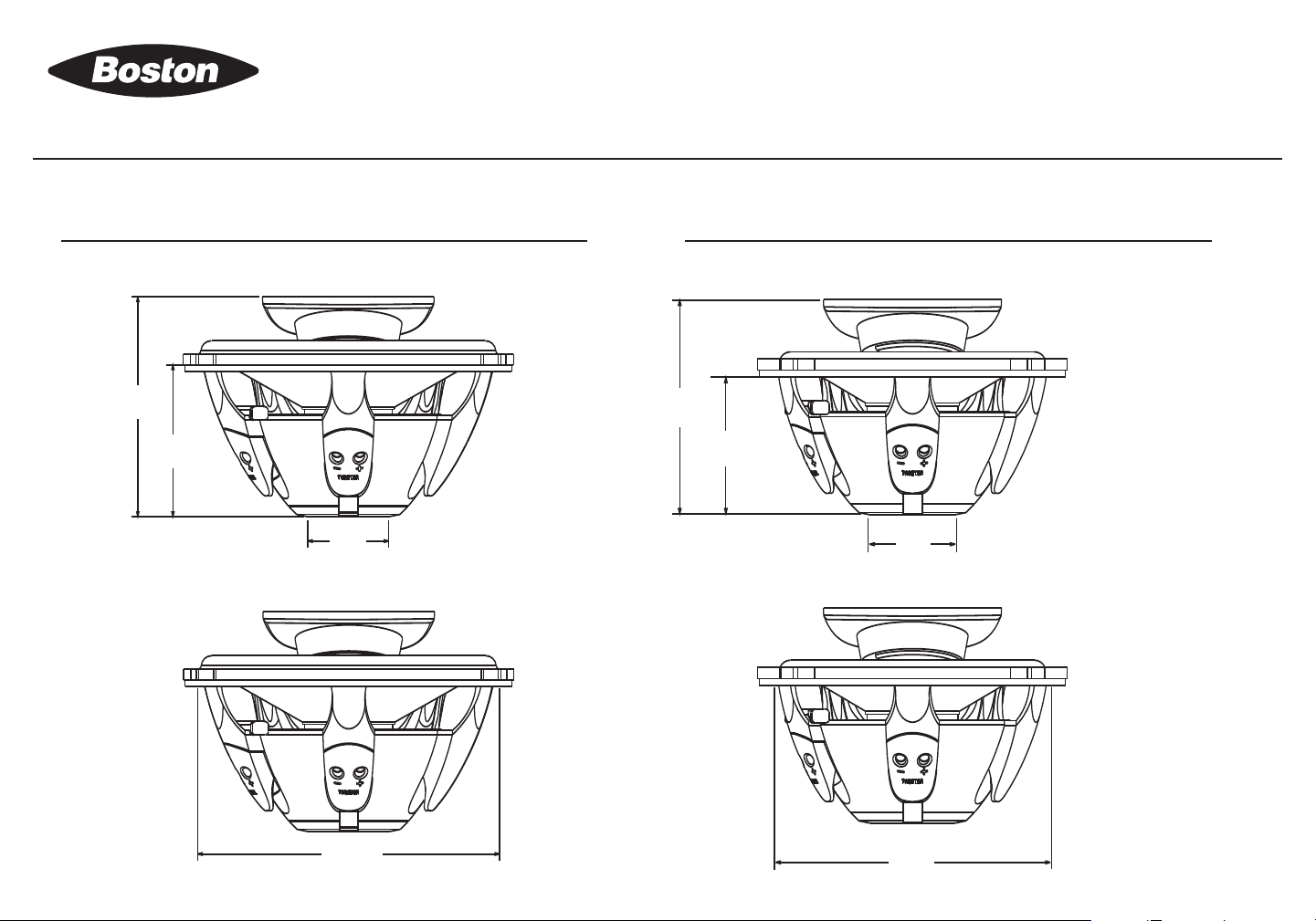
92.1mm
3.62”
61.9mm
2.54”
36mm
1.42”
119mm
4.69”
36mm
1.42”
67.4mm
2.65”
97.6mm
3.84”
134mm
5.27”
Dimensions
SPZ60 Woofer
SPZ50 Woofer
4
Page 6
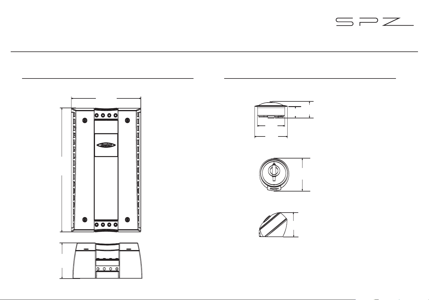
Dimensions
110mm
4.33”
197mm
7.75”
56.1mm
2.21”
18mm
.71”
27mm
1.1”
43mm
1.69”
52mm
2.05”
38mm
1.5”
51mm
2”
SPZ Crossover SPZ Tweeter
5
Page 7
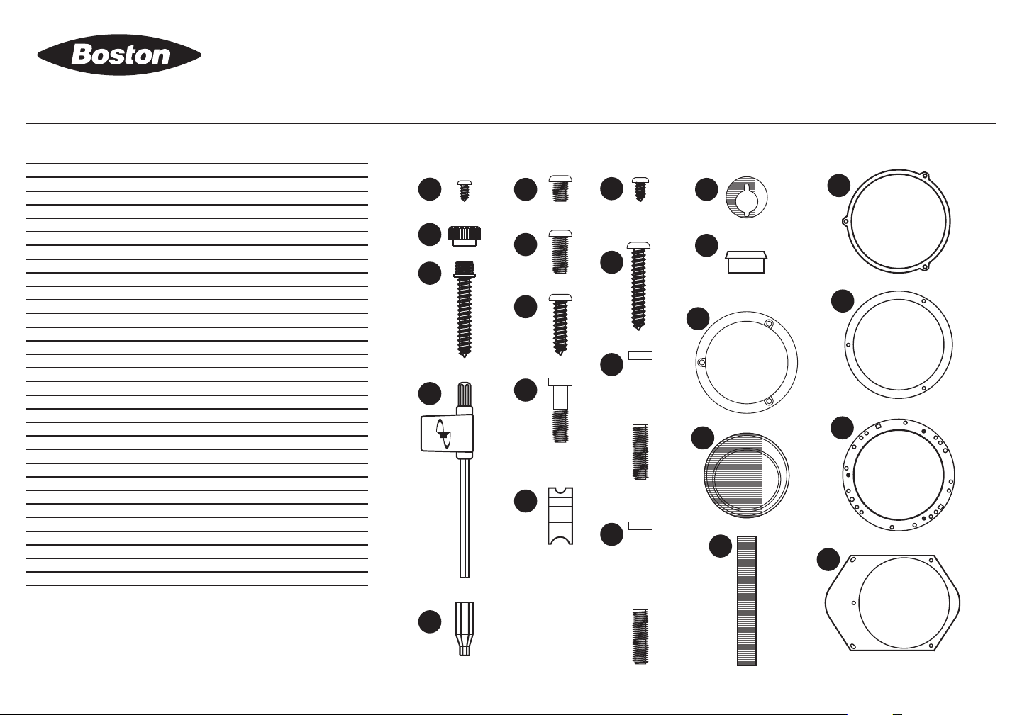
SPZ60 Included Parts and Accessories:
19
14
13
10
23
17
16
21
4
26
12
11
9
28
30
29
31
22
24
25
15
20
27
# Description Quantity
1 SPZ60 Woofer 2
2 Type-M1 1" Alloy Dome Tweeter 2
3 SPZ60 Crossover 2
4 Tweeter Grille 2
5 Tweeter Axis-Mount 2
6 Tweeter Flush-Mount 2
7 Tweeter Angle-Mount (top) 2
8 Tweeter Angle-Mount (bottom) 2
9 Woofer Gasket 4
10 Boston Hex Tool 1
11 Woofer Grille 2
12 Woofer Grille Mounting Ring 2
13 Woofer Screw 6
14 Thumb Screw (grille) 6
15
16
17 Spring Clips 4
18 Terminated Tweeter Wire 2
19
20 11⁄8" Socket Button Head Screw 16
21
22 1" Self-Tapping Screw 4
23
24 Crossover Screw (short) 4
25 Crossover Screw (long) 4
26 Phase Plug Cap 2
27 Axis Mount / Phase Plug Screw 2
28 5 x 7" (127 x 177mm) Adapter 2
29 6" (160mm) Adapter 2
30 6 1⁄2" (165mm) Adapter 2
31
1
1
⁄16" Socket Button Head Screw 6
1
⁄4" Socket Button Head Screw 6
3
⁄8" Pan Head Screw 2
1
⁄2" Self-Tapping Screw 4
3
⁄32" Hex Bit 1
1
⁄2" (13mm) Spacer 2
6
Page 8

SPZ50 Included Parts and Accessories:
32
19
14
13
10
23
17
16
21
4
26
12
11
9
22
24
25
15
20
27
# Description Quantity
1 SPZ50 Woofer 2
2 Type-M1 1" Alloy Dome Tweeter 2
3 SPZ50 Crossover 2
4 Tweeter Grille 2
5 Tweeter Axis-Mount 2
6 Tweeter Flush-Mount 2
7 Tweeter Angle-Mount (top) 2
8 Tweeter Angle-Mount (bottom) 2
9 Woofer Gasket 4
10 Boston Hex Tool 1
11 Woofer Grille 2
12 Woofer Grille Mounting Ring 2
13 Woofer Screw 8
14 Thumb Screw (grille) 8
17 Spring Clips 4
18 Terminated Tweeter Wire 2
19
20 11⁄8" Socket Button Head Screw 16
21
22 1" Self-Tapping Screw 4
23
24 Crossover Screw (short) 4
25 Crossover Screw (long) 4
26 Phase Plug Cap 2
27 Axis Mount / Phase Plug Screw 2
32 5 1⁄4” (135mm) Adapter 2
3
⁄8" Pan Head Screw 2
1
⁄2" Self-Tapping Screw 4
3
⁄32" Hex Bit 1
7
Page 9

Tweeter Installation: Flush Mount
19
18
17
6
2
4
4219176618
6
1) Drill a hole for the tweeter cup (1 3⁄4” / 45mm) making
sure that there is adequate depth available (3⁄4” / 19mm).
2) Connect the speaker wires to the tweeter cup .
3) Insert the tweeter cup into the mounting hole.
4) Insert the retaining clips and set screw and tighten.
5) Insert the tweeter into the cup, twist clockwise to lock
the tweeter into position.
Caution: Do not touch the dome of the tweeter, contact with the
(
tweeter dome will damage the tweeter.)
6) Install the tweeter grille by pressing gently into place.
8
Page 10

Tweeter Installation: Angle Mount
18
21
7
22
8
2
4
4722187181822
8
1) Drill a hole for the speaker wire and pre-drill for the
mounting screws if necessary
2) Mount the bottom cup to the mounting surface using
the provided screws routing the speaker wires
through the center hole.
3) Attach the speaker wires to the top cup and mount
it to the bottom cup using the provided screw .
4) Insert the tweeter into the cup , twist clockwise to
lock the tweeter into position.
Caution: Do not touch the dome of the tweeter, contact with the
(
tweeter dome will damage the tweeter.)
5) Install the tweeter grille by pressing gently into place.
9
Page 11

SPZ Woofer Axis Mount Installation:
10
4
2
27
5
1
425210271
5
1) Insert the axis mount into the woofer .
2) Insert and hand-tighten the retaining screw with the
provided tool .
3) Insert the tweeter into the axis mount , twist
clockwise to lock the tweeter into position.
Caution: Do not touch the dome of the tweeter, contact with the
(
tweeter dome will damage the tweeter.)
4) Install the tweeter grille by pressing gently into place.
10
Page 12

SPZ Woofer Phase Plug Installation:
10
27
26
1
10271
26
1) Insert the phase plug into the woofer .
2) Insert and hand-tighten the retaining screw using the
provided tool .
11
Page 13

SPZ50 Woofer Installation:
9
1
32
11
12
13
14
1412511151313219
1) Install the gaskets on the mounting flange of the
1
woofer and the back side of the 5
adapter ring .
2) Mount the speaker into the speaker location using
the provided screws .
3) Position the axis mount into the desired location (if
applicable), refer to page 17.
Grille Installation:
1) Position the grille on the woofer so it does not
⁄4” (135mm)
physically touch the axis mount .
2) Mount the grille ring using the four thumb screws ,
hand tighten.
12
Page 14

SPZ60 Woofer Installation with Grille:
9
9
1
29
9
11
12
2
1
14
13
1412511151312919
1) Install the gaskets on the mounting flange of the
woofer and the back side of the 6” (160mm) adapter
ring .
2) Mount the speaker into the speaker location using
the provided screws .
3) Position the axis mount into the desired location (if
applicable), refer to page 17.
Grille Installation:
1) Position the grille on the woofer so it does not
physically touch the axis mount .
2) Mount the grille ring using the three thumb screws
, hand tighten.
13
Page 15

1
9
31
3
9
30
9
23
2
16
15
SPZ60 Woofer Installation with 6 1⁄2” (165mm) VariMount™Adapter Rings:
52011516301311
9
1) Install the gaskets on the mounting flange of the
1
woofer and the back side of the
ring (if applicable).
2) Mount the speaker on to the 6
™
VariMount
plate using the provided screws . Use
alternative screw if using the
3) Mount the speaker into the speaker location using
the provided screws .
4) Position the axis mount into the desired location
(if applicable), refer to page 17.
⁄2” (13mm) spacer
1
⁄2” (165mm)
1
⁄2” (13mm) spacer ring.
14
Page 16

SPZ60 Woofer Installation with 5 x 7” VariMount™Adapter Rings:
1
31
9
28
23
15
16
20
52013115162813119
1) Install the gaskets on the mounting flange of the
1
woofer and the back side of the
ring (if applicable).
2) Mount the speaker on to the 5 x 7” VariMount
using the provided screw . Use alternative screw
if using the
1
⁄2” (13mm) spacer ring .
3) Mount the speaker into the speaker location using
the provided screws .
4) Position the axis mount into the desired location
(if applicable), refer to page 17.
⁄2” (13mm) spacer
™
plate
15
Page 17

Connecting Speaker Wires:
10
10
10
1) Strip 1⁄4” (10mm) of shield off of the speaker wires.
2) Insert the wire into the speaker terminal observing proper
polarity.
3) Hand-tighten the gold set screws using the
provided tool (2.5mm).
Note: do not overtighten the set screws.)
(
16
Page 18

SPZ Axis Mount Positioning:
10
5105
The axis mount on the SPZ woofer is designed so it can be positioned to
properly direct the tweeter’s output towards the listening position.
1) Loosen the retaining screw located on the face of the axis mount
with the provided tool (2.5mm). Turn the screw at least three full
rotations counter-clockwise.
2) Position the axis mount so that the tweeter points towards the
listening area.
3) Once the desired location has been chosen, tighten the screw on the
axis mount.
(
Note: do not overtighten the set screw.)
17
Page 19

10
25
24
Crossover Installation:
20
202524
1) Remove the four screws and located at each corner
of the top panel.
2) Once the screws are removed, the cover will lift off the
chassis.
3) Using the provided screws , secure the crossover to a
solid surface.
Note; Due to shock and vibration, the crossovers should not be installed
in the doors of the vehicle.
18
Page 20

Crossover Configuration:
Axis / Comp Mount Switch:
The “Axis/Comp” switch optimizes the output from the
crossover for the configuration of the component system. Use
the “Axis” setting if the tweeter is installed in the axis mount,
use the “Comp” setting if the tweeter is installed separate
from the woofer.
SQ1 / SQ2 Switch:
The “SQ1/SQ2” switch alters the roll-off of the SPZ woofer.
Use the SQ1 position for a standard door location. Use the
SQ2 setting if the SPZ woofer is used in a kick panel or small
3)
enclosure (less than 0.25 FT
ATTN Switch:
The “ATTN” (attenuation) switch adjusts the output of the
tweeter relative to the woofer, three adjustments allow you to
fine tune the output of the tweeter (0dB, -2dB, & -4dB).
.
NORMAL / BIAMP Jumpers:
If the SPZ crossover is bi-amplified or bi-wired, move the
jumpers to the “BIAMP” position. Refer to the System Wiring
Diagrams on page 21.
19
Page 21

SPZ System Wiring (Standard):
Standard Wiring (Coaxial Configuration) Standard Wiring (Component Configuration)
20
Page 22

SPZ System Wiring (Bi-Amplification / Bi-Wiring):
Bi-Amplification Bi-Wiring
21
Page 23

Contact Information
Contacting Boston
For questions regarding installation or service, please contact the dealer from whom you have purchased the product
or contact us directly at:
Boston Acoustics, Inc.
300 Jubilee Drive
Peabody, MA 01960
Phone #: 978-538-5000
Fax #: 978-538-5100
Email: support@bostona.com
22
AMD, TwinStage, and VariMount are trademarks and Boston, Boston Acoustics,
the Boston Acoustics logo, and RadialVent are registered trademarks of Boston Acoustics, Inc.
Specifications are subject to change without notice.
©2006 Boston Acoustics, Inc. All rights reserved.
Covered by patents issued and/or pending.
Page 24

Notes:
23
Page 25

24
Page 26

Boston Acoustics, Inc. 300 Jubilee Drive, Peabody, MA 01960 USA T: 978.538.5000 F: 978.538.5100 W: bostonacoustics.com
042-002423-0
 Loading...