

Boston Acoustics PRI665CV, PRI685CV, PRI85SUBCV User Manual
PRi665CV
W
2
3
W
4
6
W
6
1
W
8
W
4
X
r
i
D
W
2
3
W
4
6
W
6
1
W
8
W
4
X
r
i
D
PRi685CV
PRi85SubCV
In-Ceiling Speakers for Constant Voltage Installations
Parlantes de cielorraso para instalaciones de tensión constante
Haut-parleurs de plafond pour systèmes à tension constante

Specifications PRi665CV PRi685CV PRi85SubCV
Frequency Response (±3dB)
60Hz–18kHz 55Hz–18kHz 38Hz–150kHz
Audio Input Range 20Hz–20kHz 20Hz–20kHz 20Hz–20kHz
Maximum Power
Maximum Power
Maximum Power
Nominal Impedance
Switch Settings
(70V amplifier)
(100V amplifier)
(DirX connection)
(Dir\DirX connection)
(70V) 64W, 32W, 16W, 8W, 4W and Dir x (non-70V/100V)
(100V) 64W, 32W, 16W, 8W, 4W and Dir x (non-70V/100V) 34W,
65 watts 65 watts 65 watts
65 watts 65 watts 34 watts
90 watts 100 watts 100 watts
8 ohms 8 ohms 4 ohms
64W, 32W, 16W, 8W (70V)
Dir and Dir X (non-70V)
16W, 8W (100V)
Dir and Dir X (non-100V)
Sensitivity (2.83V @ 1M) 88dB 89dB 88dB
Bass Unit 6” (153mm) 8” (204mm) 8” (204mm)
Tweeter
3
⁄4” (20mm) soft dome 1” (25mm) soft dome NA
Crossover Frequency
Grille Frame Diameter
Mounting Hole Cutout
Mounting Depth
3,600Hz 3,500Hz 130Hz
113⁄8” (289mm) 133⁄4” (350mm) 133⁄4” (350mm)
915⁄16” (253 mm) 123⁄8” (314mm) 123⁄8” (314mm)
(with 1/2” dry wall) 9
3
⁄8” (239mm) 113⁄4” (299mm) 113⁄4” (299mm)
Weight 11 lbs (5.0kg) 19 lbs (8.6kg) 18 lbs (8.2kg)
Maximum Ceiling Height 18 feet (5.5m) 22 feet (6.7m) 22 feet (6.7m)
2

3
Description
Thank you for purchasing the PRi series CV speakers. These speakers incorporate high-quality components that
produce the famous Boston sound. They are housed in a metal enclosure that makes them easy to install and
meet the stringent requirements of electrical codes throughout the country for plenum-rated enclosures. Such
enclosures are often required by building codes in commercial applications and residential applications such as
townhomes or condominiums. They have built-in transformers for use is constant voltage distribution systems—
either 70V or 100V depending on the country in which it is used. So they are ideally suited for multi-speaker
commercial installations.
The bass drivers in the PRi models have a DCD mica-filled copolymer cone with a butyl rubber surround. An inte
grated, forward-facing tuned port extends bass response. The soft dome tweeters of the PRi665 and PRi685 have a
pivoting mount. Insulation inside the enclosures helps control resonances and improves room-to-room isolation.
Additional Key Features
• The PRi speakers meet the following agency requirements:
UL1480 Listed, UL2043 Testing Standard, NFPA70 and UL94-V0 (all plastic materials)
• Moisture resistant design with rust-resistant hardware.
• All parts are UV resistant.
• Built-in cable clamp with an opening for industry standard conduit clamps.
• 4-pin, 2-piece Molex connector for easy connection and daisy chaining of speaker wires.
• Safety wire attachment tab.
-
About Installation
NOTE: This manual is written for the professional installer and assumes skill in the proper use of hand and power
tools, knowledge of local building and fire codes, and a familiarity with the environment behind the wall or ceil
ing in which the speakers will be installed.
correctly and to make sure that local codes are met. Boston Acoustics strongly recommends the use of
safety cables in all installations.
Read this manual completely before beginning the installation. Have a plan for each step of the entire installa
tion. Please keep your manual in a safe place in case you need to refer to it later.
It is the professional installer’s responsibility to install the speakers
-
-
The grille and frame of the PRi speaker can be painted to match its surroundings. If you plan to paint your
speakers, see the information in the “Painting the PRi Speakers” section on page 12.
WARNING: Always turn off the amplifier or receiver when connecting speakers or any other components to the
system.
Speaker Installation Locations
*,ÈnxÊÉÊ*,nx-ÕL *,ÈÈx
Ê
£x
ɣȸ
ÓxÎ
Ê£Ó
Î
Én¸
Σ{
Ê£{
Î
Én¸
ÎÈx
££
£x
ɣȸ
ÎäÎ
When selecting installation locations you must take into account both mechanical and acoustical factors. The
pivoting tweeter of the PRi665 and PRi685 helps them produce excellent sound even when they are installed in
less than ideal locations.
The mechanical factors have to do with the structural parts inside the ceiling. If you are installing the speakers in
new construction it is easy to take this into account. Simply select
the installation locations before the wall board goes up. In retrofit
installation things are more complicated. First, you must know the
locations of the ceiling rafters to be sure the installation location is
between them. An electronic stud finder can help. You must also
know the depth of the rafters to be sure there is enough room above
the ceiling for the speakers.
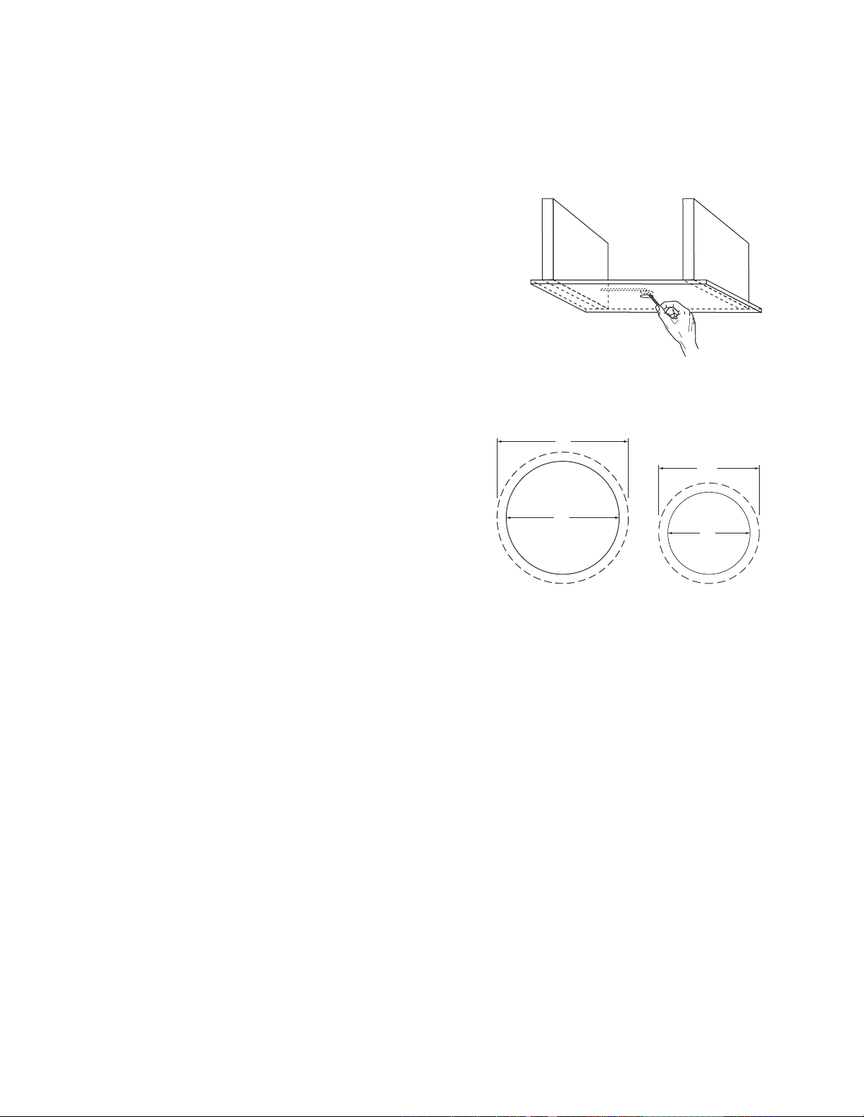
The locations of heating outlet ducts and electrical fixtures can help
indicate where there may be obstructions in the ceiling. As a final
check, before cutting the hole for installation, drill a small hole at the center of the installation location. Insert a
long, bent piece of wire and move it around to confirm that there are no obstructions.
Installation in drop ceilings is easy since ceiling tiles can be
removed for access to the installation location. Drop ceiling
support brackets are included with the CV versions of the PRi
speakers. Their use is described on page 13. Be sure there is
adequate room above the ceiling grid for the speakers. See
the Mounting Depth specifications on page 2.
In addition to the area for the installation cutout you must
allow an additional 1” of clearance around it. This ensures
that there is room for the mounting clamps to deploy. Mount
ing depth is typically not a problem. But you should check the
mounting depth using the wire probe method described above. Also check for heating ducts, plumbing, electri
-
cal wiring and insulation could impede the installation.
Also remember that you must run speaker wires from the amplifier to the installation location. This is easy in new
construction installations. It is also easy in drop ceiling installations once the wire is in the area above the ceiling
grid. In retrofit installations wire routing is more difficult. Be sure to take this into account when planning the
installation.
Speaker Spacing
To calculate the required spacing of speakers in a room and what the tap setting is you need to perform the following calculations or you can download the BA Commercial Speaker Calculator from the Boston web site.
To get the calculator you will need an internet connection and you will go to
http://www.bostonacoustics.com/pri
Find a PRi Speaker Product Page. You will see a place to download the tool. To install and use this tool, follow
the instructions provided with the calculator.
To do the calculations by hand, you will need to follow the steps below:
4
5
Room Dimensions: use inches instead of feet and inches
/Ê®
-«>V}
7/Ê7®
-«>V
}7ÊÉÊÓ
-«>V}
7
-«>V}ÊÉÊÓ
W
2
3
W
4
6
W
6
1
W
8
W
4
X
r
i
D
W
2
3
W
4
6
W
6
1
W
8
W
4
X
r
i
D
Listener Position: Standing =64.4 inches (164mm); Sitting = 48.5 inches (124mm)
Speaker F Values
Speaker Good Better Best
PRI665CV 3.128 2.606 2.086
PRI685CV 2.619 2.183 1.746
Note: Good coverage = ± 6dB; Better coverage = ± 3dB and Best coverage = ± 1.5 dB. Typically we recommend Better coverage but if cost constraints make this impossible for the customer, then use the Good cover
age. Best coverage is where you want very even coverage and typically either low or high SPL.
H
= Ceiling Height – Listener Position
diff
Spacing
max
= H
x Speaker F value
diff
-
Columns = Roundup ( room length / Spacing
Rows = Roundup ( room width / Spacing
Spacing
Spacing
= room length / columns
L
= room width / rows
W
First speaker is placed at (Spacing
Next column is placed at (Spacing
Next Row is placed at (Spacing
W
max
/2, Spacing W/2)
L
/2+ Spacing L) … and so on until all columns are placed
L
/2+ Spacing W) … and so on until all columns are placed
max
)
)
To determine how many subwoofer you require for a room, the calculations are much easier. You determine the
cubic feet of the room (L x W x H all in feet), divide this number by 15,000 and round up.
To determine the max SPL in the room, you need to know H
in feet and the Max SPL of the speaker. Use the
diff
following Max SPL at 3 feet for each speaker is:
Speaker Type Max SPL
PRi665CV 101 dB
PRi685CV 103 dB
PRi85SubCV 101 dB
Note: These are not the absolute max SPL for the speaker. These are
guidelines to use for designing systems.

You also have to choose a desired level at the listener location. Typical values are:
Desired SPL Level
Background 85 dB
Mid-ground 91 dB
Foreground 96 dB
Note: Background is usually in quiet rooms that people do not want to shout to be heard or that the music is
to provide ambience and is not a focal point. Mid-ground is when you have a lot of ambient noise and want
the music to be heard over this noise. Foreground type applications are usually where the music or voice being
amplified are a focal point and either must be heard to entertain, inform or enlighten.
A general rule of thumb is that you lose about 1dB per foot. The Max SPL is at the highest Tap setting allowed.
Therefore, to determine the tap setting you use Hdiff to subtract the SPL difference from 3 feet to the listener ear
location. Once you have this you have the Max SPL at the listener location. Now you lower the tap until you get
the nearest value above the desired SPL.
SPL at listener = Speaker Max SPL – (H
To Calculate the tap setting you take [SPL at Listener] – [desired SPL] = SPL
Tap clicks = round down(SPL
diff
/3)
/ 12) +3
diff
diff
So starting with the speakers max tap setting (64 for all speakers) and going down tap clicks gives you the tap
setting for that speaker.
Example: If SPL
= 10 then tap clicks = 3 and the tap setting is 64 => 32 => 16 => 8 is the correct setting of the
diff
transformer.
The last step in the system design is to calculate the amplifier power needed. This calculation must take into ac
count a 20% loss of power to the speakers due to transformer losses.
Amp Power = [total number of speakers] x [tap setting] x 1.2
As an example:
Assume the room is 60 ft x 40 ft x 12 ft high. Listeners are usually standing.
W = 40 x 12 = 480 in.
L = 60 x 12 = 720 in.
Ceiling H = 12 x 12 = 144 in.
H
= 144 – 64.4 = 79.6 in
diff
Desired SPL = Background = 85dB
-
If we use the Pri665CV then the calculations for better coverage are:
Spacing max = 79.6 x 2.606 = 207.4 in
Columns = Roundup( 720 / 207.4) = Roundup(3.47) = 4
Rows = Roundup( 480 / 207.4) = Roundup(2.31) = 3
Spacing L = 720 / 4 = 180 in = 15 ft
Spacing W = 480 / 3 = 160 in = 13 ft 4 in
6
7
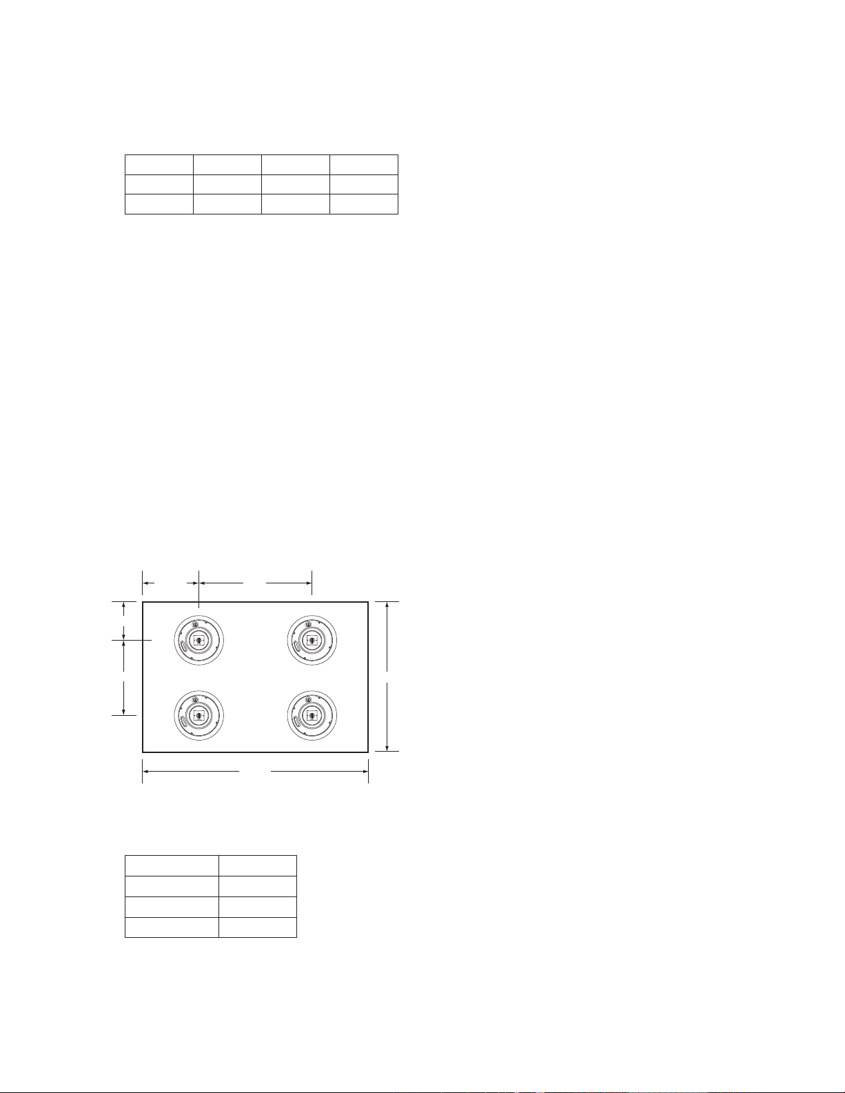
So the Following Layout for the room is done:
-«>V}7ÊÉÓ
ȽÊn»
-«>V}
7
£Î½Ê{»
-«>V}
7
£Î½Ê{»
-«>V}ÊÉÓ
Ç°xÊvÌ°
-«>V}
£xÊvÌ°
-«>V}
£xÊvÌ°
-«>V}
£xÊvÌ°
The Max SPL at the listener location is 101 – (79.6 / 12) + 3 = 97.4 dB The desired SPL is 85 dB so you do the fol
lowing calculation:
Max SPL – Desired SPL = 12.4 dB.
Divide this by 3 = 4.13 so use 4 steps down. This is the number of tap settings to lower the system by – so we will
use 8W taps. As this is a rule of thumb, you will need to test the SPL in the room to determine the proper tap set
-
ting. If you want more head room on the amplifier, set the taps to 16W.
The last calculation you need to do is the total amp power required, taking into account transformer losses in
the system which equals 20% of available power. There are a total of 12 speakers @ 8 W each so you need:
12 x 8 x 1.2 = 115 watts of amplifier power.
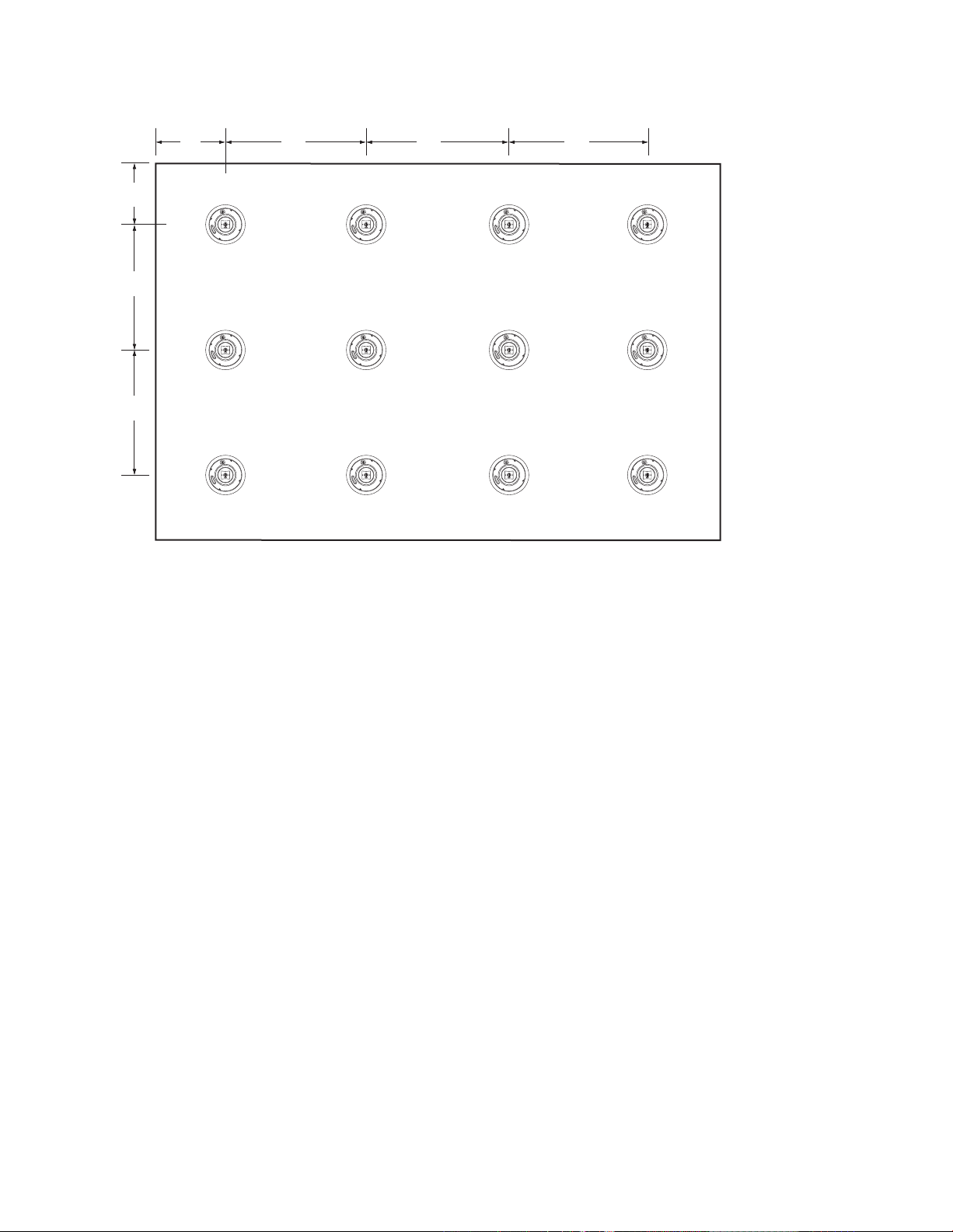
Just to show how this gets effected by speaker choice, let’s assume we will use the PRi685CV instead of the
PRi665CV. In the same room and with the same SPL desired and coverage.
Spacing max = 79.6 x 2.183 = 173.77 in
Columns = Roundup( 720 / 173.77) = Roundup(4.14) = 5
Rows = Roundup( 480 / 173.77) = Roundup(2.76) = 3
Spacing L = 720 / 5 = 144 in = 12 ft
Spacing W = 480 / 3 = 160 in = 13 ft 4 in
As you can see we need more speakers (15 versus 12), but we get a higher potential SPL and better frequency
response.
The Max SPL at the listener location is 103 – (79.6/12) + 3 = 99.4 dB. The desired SPL is 85 dB so you do the fol
lowing calculation:
Max SPL – Desired SPL = 14.4 dB

Divide this by 3 = 4.75 or 4 steps. This is the number of tap settings to lower the system by – so we will use 8W
*,Ê-«i>iÀ
iVÌÀ
*Õ}
iVÌÀ
taps. (Note that this system already has 2 dB of head room more than the 6” system.)
As this is a rule of thumb, you will need to test the SPL in the room to determine the proper tap setting. If you
want more head room on the amplifier, set the taps to 16W.
The last calculation you need to do is the total amp power required, taking into account transformer losses in the
system which equals 20% of available power. There are a total of 12 speakers @ 8 W each so you need:
12 x 8 x 1.2 = 115 watts of amplifier power
or 12 speakers @ 16W:
12 x 16 x 1.2 = 230 watts of amplifier power.
So for the room above we have a 60 ft x 40 ft x 12 ft high. = 28,800. This means you should use 2 subwoofers. If
you want extreme bass, use 4, but in most applications, you will want to use 2. Placing these in the room is easier
and provides more flexibility; remember to keep them at least 2 feet from any wall or corner. If you put them near
a corner you gain 6dB of output. As far as tap settings, use a similar calculation to the speakers.
The Max SPL at the listener location is 101 – (79.6 / 12) = 94.4 dB (this is more conservative than the speakers,
but allows for stronger bass in the room). If you want background levels in the room, then you will want to set the
taps to 8W each.
As you can see from these calculations using the Boston Acoustic Commercial Speaker Calculator will give you
these designs much easier. We encourage you to use it instead of doing the calculations by hand.
Speaker Wires
After the speaker installation locations have been chosen, you must run wires to the amplifier that drives them.
The electrical codes in your area may require the use of special wire that is resistant to exposure called “plenum
rated” wire. Check with an electrical safety inspector in
One of the main advantages of high voltage CV systems is that relatively light gauge wire can be used, even over
long distances. In most installations 18 gauge wire will be more than enough. Only in very high power systems is
anything heavier needed.
your area to see if such wiring is required.
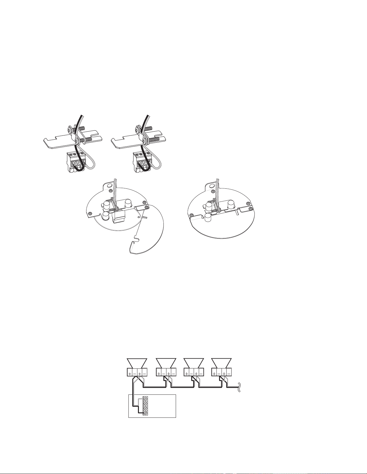
Speaker Connection Polarity
It is important that all the speakers in a system are hooked up with the same polarity or “in phase.” The PRi series models are supplied with a Molex plug-in connector to facilitate installation. Speaker wires are connected to
the plug-in connector then, just before installing the speaker, the Molex connector is plugged in.
This illustration shows the connector on the speaker and the plug-in connector for the speaker wires. Note the
label beside the speaker connector. It shows the middle two pins on the connectors are “–” and “+”. The outer
two pins are labeled “LOOP +” and “LOOP –”. The “LOOP” connections are con
nected to the regular “+” and “–” connections inside the speaker and facilitate
connecting multi-speaker installations. Use the color coding or other marking on the
speaker wires to be sure that the “+” terminal of the amplifier is connected to the
“+” terminal of the speaker, and “–” is connected to “–”, at every connection.
-
8
9
Connecting the Speakers
ÇäÊ6Ê>«wiÀ
ÇäÊ6ÌÃ
""* ""*
Çä6
Óx6
{Ê"-
"
ÇäÊ6ÌÃ
""* ""*
ÇäÊ6ÌÃ
""* ""*
ÇäÊ6ÌÃ
""* ""*
Unscrew the fasteners on the back of the speaker that hold the wire clamp in place. Open up the clamp and insert about 2” of wire through the opening. Tighten the clamp screws to secure the wire. Note: If there is a jacket
around the two wire conductors fasten the clamp to the jacketed part of the wire. Remove the jacket from the
part of the wire that extends beyond the clamp.
Separate the two conductors of the wire. Remove about 3/8” of insulation from the end of the wire. Insert the
wires into the appropriate terminals on the connector and tighten the screws on the top of the connector to
secure the wire. Be sure there are no loose strands of wire.
Just before the speaker is mounted plug the connec
tor into the back of the speaker. Set the wire clamp in
place and tighten the fasteners to secure it. Finally pivot
the moveable cover plate into position and tighten its
fastener to hold it in place.
Multiple Speaker Connections
The other main advantage of high voltage CV systems is all the speakers being driven by a given amplifier channel are basically connected in parallel. The impedance load concerns of conventional systems do not apply.
There are two ways to connect a series of PRi CV speakers. Examples are shown below.
The first example shows how CV systems are typically connected. The wire from the amplifier to the first speaker,
and for all the following speaker-to-speaker connections, are all connected to the regular “+” and “–” terminals.
With this type of connection all the speaker in the chain will operate even when one or more of the speaker con
nectors is unplugged.
-
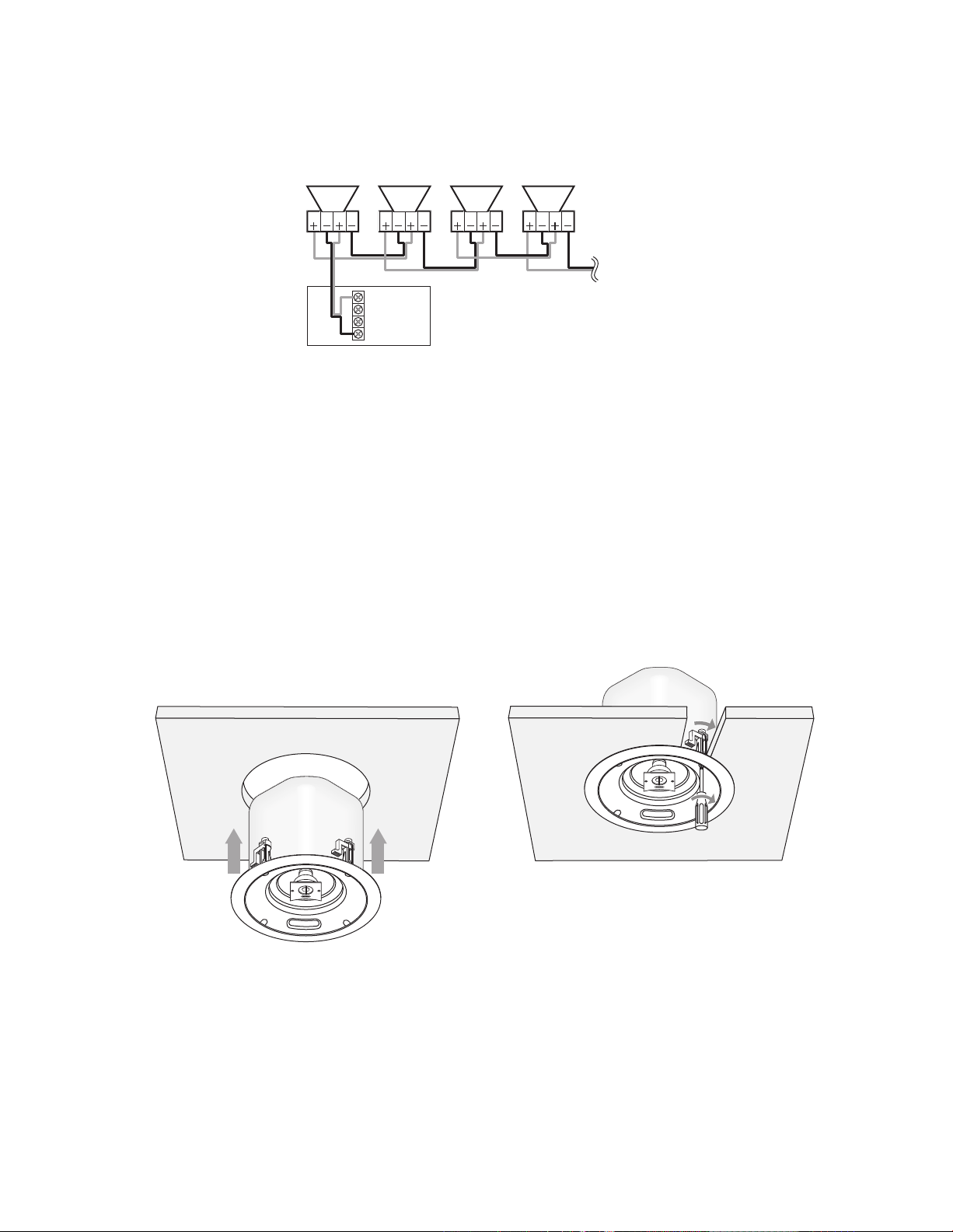
The second example shows the wires to the second speaker and all the following speakers connected to the
ÇäÊ6Ê>«wiÀ
Çä6
Óx6
{Ê"-
"
ÇäÊ6Ì
""* ""*
ÇäÊ6Ì
""* ""*
ÇäÊ6Ì
""* ""*
ÇäÊ6Ì
""* ""*
“loop” terminals. The “loop” terminals are connected to the regular “+” and “–” terminals inside the speaker.
This makes connecting the wires to the terminals easier. But it also means that if the one speaker is unplugged
for any reason the signal to the following speakers is cut off.
Parallel connections can also be made by connecting wires from all the speakers directly to the amplifier ter
minals, typically referred to as “home run” connections. This typically results in more wire being used – usually
something you want to avoid.
The information above only applies to 70V systems. If you use the Dir X setting of the switch on the front, bypass
ing the transformer, connect the speakers as you would any conventional low impedance speakers.
Installing the Speakers
Once the installation location has been prepared and the speaker has been connected, the installation of the
speaker is easy. Simply lift the speaker into the installation hole. Use a phillips screw driver to pivot the mounting
clamp arm outward and draw them down against the back of the mounting surface. Then gradually tighten the
mounting clamp screws, alternating among them, until the speaker is firmly clamped in place. Do not use exces
sive force when tightening the mounting clamp screws.
-
-
10

11
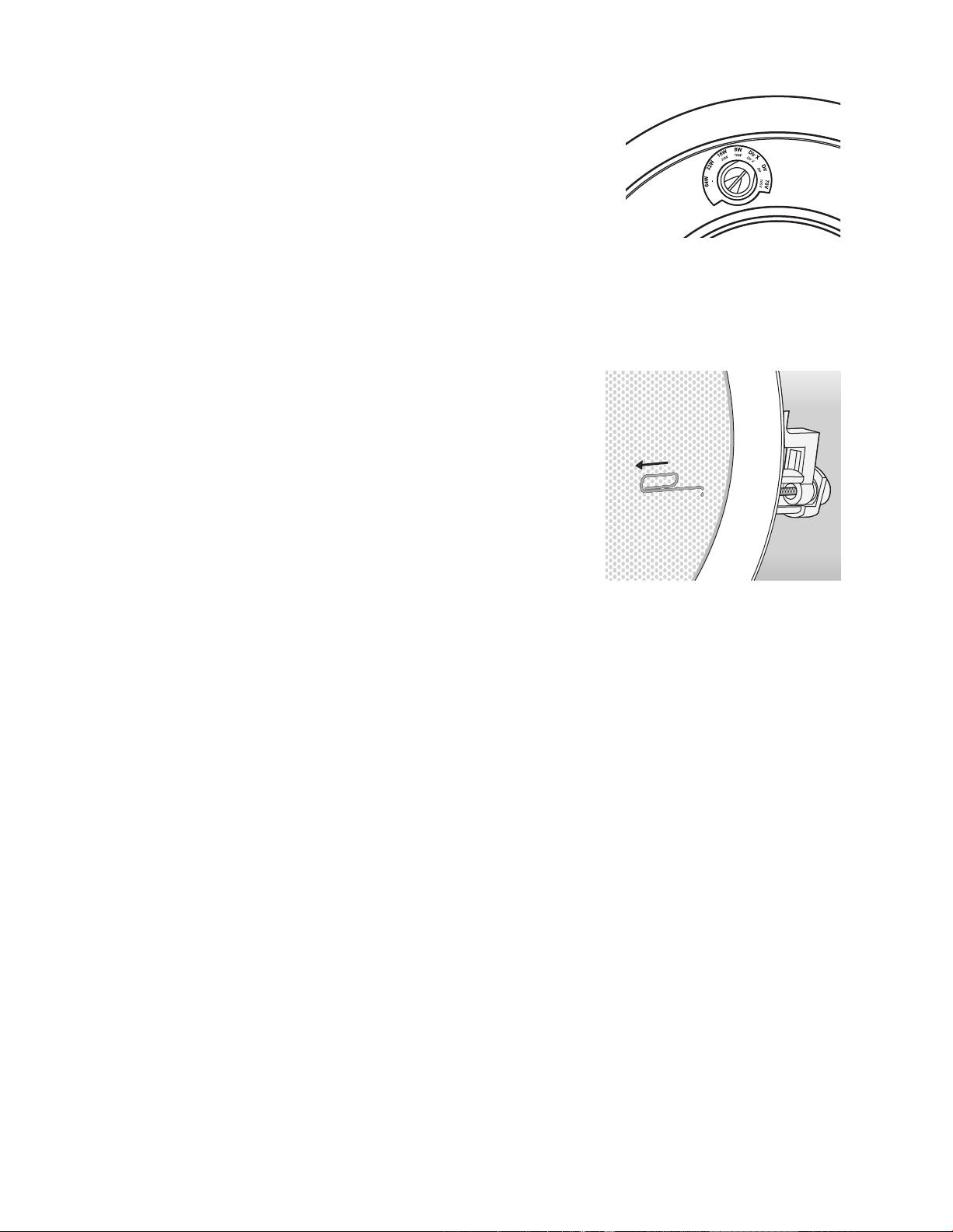
Adjusting the Transformer Tap Switch
W
2
3
W
4
6
W
6
1
W
8
W
4
X
r
i
D
The switch on the front of the speaker frame selects the secondary
transformer tap that supplies the signal to the speaker. It serves to control
the distribution of the amplifier power to the various speakers and cor
respondingly can be used to balance the relative output of the speakers.
The switch has setting for power levels of 4, 8, 16, 32 and 64 watts. There
is also a “DirX” bypass setting should you want to connect the speakers
to a conventional amplifier at some point in the future. (The PRi85Sub has
a slightly different group of setting. See the information on the following
page.)
To determine the proper tap settings, follow the directions in the Speaker Spacing section on page 6 of this
manual. These instructions provide the initial setting of all speakers in the system. After installing the system,
verify that the SPL and balance between the speakers is correct. If not, adjust the tap setting for each speaker.
-
Keep in mind the power available from the amplifier. The total of the power level selected with the switch set
tings, plus a 20% “transformer loss factor” will tell you if the amplifier has enough power for the configuration.
For example, say you have 6 speaker on a given amplifier channel, three with the transformer set to 16 watts and
three set at 32 watts. The calculation would be:
[(3 x 16) + (3 x 32)] x 1.2 = 172 watts
As long as you have that much power available then you can drive the combined speakers properly. It you set all
six of the speakers to the 32 watt setting then you would need 230 watts:
(6 x 32) x 1.2 = 230
Once you are satisfied with the transformer switch settings press the speaker grilles into place to complete the
installation.
Listening Levels and Power Handling
The listed power recommendations assume you will operate your system in a way that will not produce distortion. Even very rugged speakers can be damaged by a relatively low power amplifier if it is producing distortion.
If the sound is harsh or gritty turn down the volume. Prolonged or repeated operation of your speaker with a
distorted signal from the amplifier can cause damage that is not covered by the warranty.
Additional Information on the PRi85Sub
The PRi85Sub in-ceiling subwoofer has a built-in passive crossover. The 8, 16, and 32 watt settings of the transformer
then route the signal through the crossover. The “DirX” setting bypasses the transformer should you want to
connect the speaker to a conventional amplifier at some point in the future. This setting still passes the signal
through the crossover so it should be used if speaker is receiving a full range signal.
The PRi85Sub also has a “DIR” setting which bypasses both the transformer and crossover. Use this setting if the speaker is being driven by
a conventional amplifier that has a built-in crossover, such as the Boston
Acoustics SA-1.
NOTE: The DIR position is provided as a way to use an amplified LFE
signal from a receiver and should be limited to 30Hz to 750Hz – to ensure
the product is protected. We do not recommend or warranty this product
if this frequency limitation is not used.
Removing the Grilles
Should you need to remove the grilles for any reason use a paper clip bent into a small hook. Slip the hook
through one of the holes and pull the grille straight out. You may need to pull one edge part of the way out them
move to the other edge and gradually work the grille out of the frame.
Painting the PRi Speakers
You can paint the exposed part of the frames and the grilles of your
speakers to match the room. A paint shield is provided to protect the
speakers.
Most paints, especially water based paints, don’t adhere very well to
plastic surfaces or surfaces already cover with glossy paint. So you will
need to apply a primer coat. Use a primer recommended for plastic sur
faces. Be sure it will produce a surface that will bond with the paint you
are using.
apply primer to the grille.
NOTE: Depending on the type of paint that will be used for the final coat you may or may not need to
-
Remove the grille as described in the preceding section. Put the paint shield over the front of the speaker. Apply
masking tape to all other part that should be protected. Be sure to cover the mounting clamps and the terminal
cover. Be sure the surfaces to be painted are clean and free of dust, lint, etc.
Apply two or more light coating of primer. Let the primer dry thoroughly between coats. You’ll get better results
and reduce the chance of drips or runs using several light coatings. Lighter coats also reduce the chance the
holes in the grilles will become plugged with paint. Let the paint dry completely. Remove the paint shield and
re-insert the grille.
12
13
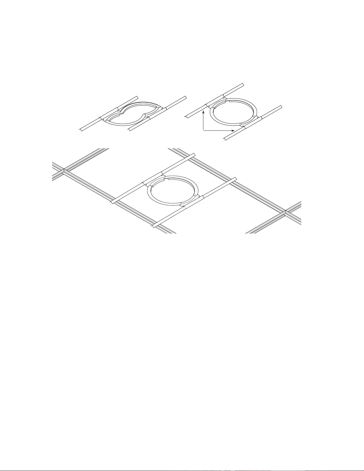
Ceiling Brackets
iÝÌi`>LiÊÀ>Ã
Special brackets are supplied with the CV versions of the PRi speakers that make it easy to mount them in a
suspended ceiling. The bracket rests on top of the ceiling grid so the weight of the speaker is supported by the
grid, not the ceiling panel. The bracket has a “foldable” design, shown on the left below, that makes it easy to
maneuver the bracket through the mounting hole.
In this illustration the ceiling grid is
shown without the panels.
Once the mounting hole is cut in the ceiling panel pass the folded bracket through the hole and pivot it into its
normal shape as shown below on the right. Then extend the rails so they rest on the ceiling grid. Set the bracket
so the flanges that extend down from the arcs surround the installation hole. Then connect the speaker and
clamp it in place as in a regular installation.
NOTE: Boston Acoustics strongly recommends the use of safety cables in all installations. This is particularly
important when the PRi speakers are installed in suspended ceilings. Attach one end of the security cable to the
tab on the back of the speaker and fasten the other end to a strong structural element of the building.
The ceiling bracket can also be used in dry wall ceilings. Cut the standard required hole for the speaker in the
drywall. Insert the collapsed bracket through the hole and expand it into normal shape. The orientation of the
extendable rails is not important. They can remain fully retracted. If the installation location is very tight the ex
tendable rails can be removed so the center section will serve as a plaster ring.
-

Limited Warranty
Boston Acoustics warrants to the original purchaser of our PRi series speakers that they will be free of defects in
materials and workmanship for a period of 5 years from the date of purchase.
Your responsibilities are to install and use them according to the instructions supplied, to provide safe and se
cure transportation to an authorized Boston Acoustics service representative, and to present proof of purchase in
the form of your sales slip when requesting service.
Excluded from this warranty is damage that results from abuse, misuse, improper installation, accidents, ship
ping, or repairs/modifications by anyone other than an authorized Boston Acoustics service representative.
This warranty is limited to the Boston Acoustics product and does not cover damage to any associated equip
ment. This warranty does not cover the cost of removal or reinstallation. This warranty is void if the serial number
has been removed or defaced. This warranty gives you specific legal rights, and you may also have other rights
which vary from state to state.
-
-
-
If Service Seems Necessary
First, contact the dealer from whom you purchased the product. If that is not possible, write to:
Boston Acoustics, Inc.
300 Jubilee Drive
Peabody, MA 01960 USA
Or contact us via e-mail at:
support@bostona.com
We will promptly advise you of what action to take. If it is necessary to return your PRi series unit to the fac
tory, please ship it prepaid. After it has been repaired, we will return it freight prepaid in the United States and
Canada.
-
This symbol found on the product indicates that the product must not be disposed of with
household waste. Instead, it may be placed in a separate collection facility for electronic waste or
returned to a retailer when purchasing similar product. The producer paid to recycle this product.
Doing this contributes to reuse and recycling, minimizes adverse effects on the environment and
human health and avoids any fines for incorrect disposal.
14
 Loading...