

Page 1
High Performance Multi-Purpose Speaker
Bravo II
Page 2

Specifications
Frequency Response (±3dB) 80Hz–20,000Hz
Recommended Amplifier Power 15–125 watts
Nominal Impedance 8 ohms
Sensitivity [1 watt (2.83v) at 1m] 89dB
Bass Unit 41⁄2" (115mm) copolymer
Tweeter 1" (25mm) black anodized
aluminum dome with AMD
Crossover Frequency 2500Hz
Dimensions (HxWxD) with corner fillers 141⁄4 x 61⁄2 x 51⁄4" (362 x 166 x 134mm)
Dimensions (HxWxD) without corner fillers 141⁄4 x 61⁄2 x 41⁄4" (362 x 166 x 108mm)
Weight 5 lbs (2.25kg)
Finish White, black, or silver textured ABS
with matching metal grille
Description
The Boston Bravo™II is a multi-purpose, high performance compact loudspeaker. The Bravo II, which uses Boston’s
patented one-inch aluminum dome VR
mounting bracket or rear stand to be mounted or placed virtually anywhere in any room.
®
tweeter with AMD and a 4
1
⁄2-inch woofer, can be combined with its supplied
The Bravo II is essentially one-quarter of a cylinder, allowing it to be mounted vertically at any height in a corner, or horizontally at the top of a wall, where wall and ceiling meet. Attaching the Bravo II to any surface is as simple as mounting
the bracket to the wall, removing the grille from the speaker, and then attaching the speaker to the bracket using the supplied screws. Once the grille is placed back on the speaker, the means of attachment becomes virtually invisible.
Additionally, the Bravo II can be placed either horizontally or vertically on any flat surface, such as a table or a shelf.
Horizontally, it can either angle upward by resting on its two corner fillers or sit untilted using the rear stand.
Because it is designed as a high-performance, general-purpose speaker, the Bravo II is suitable for any high-fidelity application where it is important that the speaker blends into its surroundings. The Bravo II is well suited for background and
whole house music applications. The Bravo II’s highly flexible mounting bracket allows it to be placed in a wide variety of
locations, and to for the speaker to be angled for optimum sound quality and three-dimensional imaging. When a pair is
placed vertically in the corners of a room, the Bravo II creates an unusually wide listening window, providing true stereo
sound reproduction over a broad area.
For full-range applications, it is recommended that the Bravo II be used in conjunction with one of Boston’s powered subwoofers. The Bravo II’
obust design allows it be used with full-range signals and amplifiers rated between 15 and 125 watts. Please
Bravo II’
s r
s low frequency limit is 80Hz, allowing for a great deal of placement flexibility for the subwoofer. The
note that the Bravo II is not magnetically shielded. Therefore, it should not be placed closer than 18 inches from a tube
television. The Bravo II may be used safely near pr
ojection and plasma televisions.
Also available; The Boston Bravo II Center. The Bravo II Center is sonically matched to the Bravo II and features
®
Magnaguard
magnetic shielding allowing for use on or near tube televisions without interference.
2
Page 3
How to Connect Your Speakers
1
/
4
"
speaker terminal
amplifier or receiver
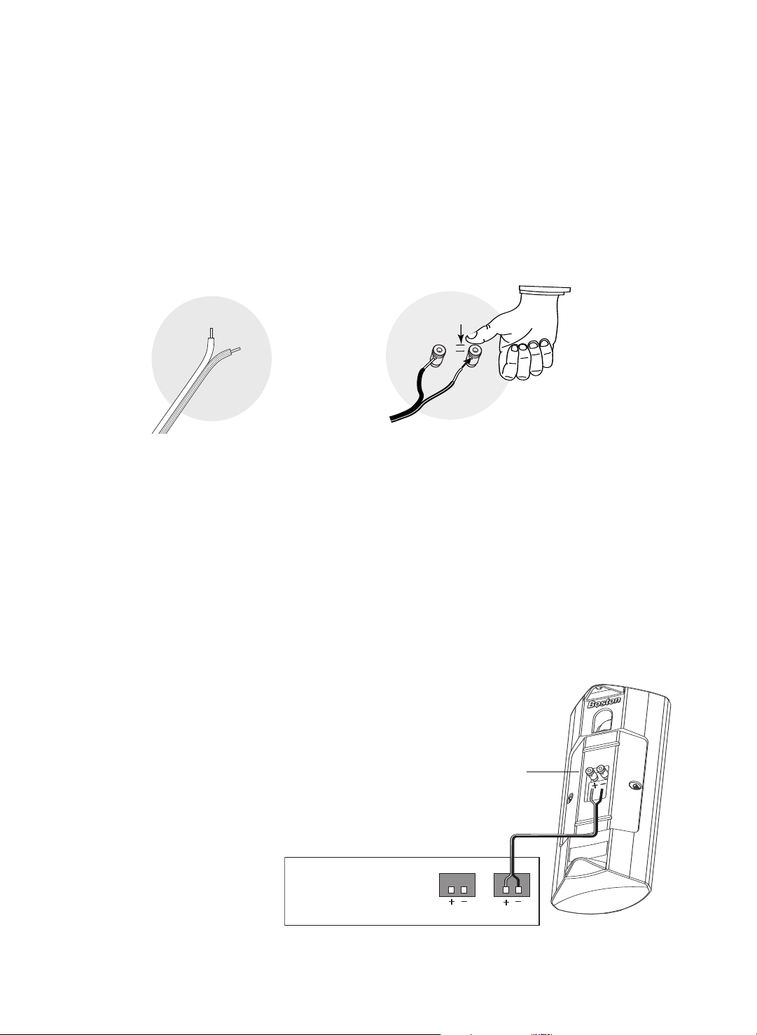
Correctly wiring your speakers is important for achieving the best sound quality. Wiring should take just a few
minutes, but it’s important to do it carefully, since incorrect wiring (such as reversed connections) can result in a poor
soundstage and poor bass.
We recommend 18-gauge wire or thicker for runs up to 15 feet (4.5m), and 16-gauge wire or thicker for longer runs.
Separate the fi
speaker wire to expose the two conductors and tightly twist the wire strands.
WARNING: To prevent electrical shock hazard, always switch off the amplifier or receiver when making connections
to the speaker.
rst few inches of the wire conductors. Strip off
1
⁄2-inch (12mm) of insulation fr
om the ends of each
IMPORTANT: Typically, one side of the wire is smooth.
Connect this side to the
other side has a rib or stripe. Connect this to the
+ (red) connection.
– (black) connection. The
Using the spring terminal posts: The spring terminal
posts permit easy connection to banana plugs, spade
lugs, and bare wire.
Push the the top of the terminal down by approximately
1
⁄4-inch, exposing the hole. Insert the wire in the hole
and release the terminal.
Connecting the Boston Bravo to Your Amplifier or Receiver
1. Connect the speaker terminals to the
amplifier speaker outputs.
2. Make sure the speaker cable is corectly routed through the mounting
r
bracket.
(see Mounting Options)
3. When making all connections, be sure
to connect
+ to + (red) and – to – (black).
4. If using the Bravo II with a subwoofer,
set the receiver's bass management to
SMALL in the speaker setup menu. This
will diver
from the center channel to the main
speakers and/or subwoofer
y low frequencies away
t ver
.
3
Page 4

fi
ller cap removed
self-adhesive
rub
ber feet
applied
bra
cket
removed
angle/corner
mounting holes (4)
2 per side
single gang electrical
box mounting holes
speaker-to-bracket
mounting holes (2)
1 per side
single gang
electric outlet
opening
speaker cable run
holes (2)
on top and bottom
flat mounting holes (4)
2 per side
Using the Bravo II on a Flat Surface
corner fillers facing in
bracket
removed
The Bravo II can be used on a fl
at surface, such as a table, shelf or the floor. For horizontal placement that angles up
at 45º, both corner fillers must be used and the bracket must be removed. For untilted horizontal placement, the
ear stand must be used
r
with the mounting bracket attached (see “Mount the Speaker to the Bracket” and the
“Rear Stand Installation Instructions” found on page 6. For vertical applications mount the four supplied rubber
feet to the bottom of the speaker. Attach two of the supplied self-adhesive rubber feet so that its edge contacts the
back edge of the cabinet. Apply two more self-adhesive rubber feet to the recesses at the front of the cabinet.
Mounting the Bravo II
Identify the Bracket
In its packing material, the Bravo II’s
mounting bracket is fitted into the back
of the speaker. Remove the tape that is
temporarily holding the bracket to the
speaker, and then pull the bracket away
mine
om the back of the speaker
fr
how the Bravo II is to be mounted to the
wall or ceiling. It can be mounted either
horizontally or vertically, either on an
open section of wall, or where two or
three room surfaces meet. Refer to the
illustration her
e to deter
holes on the Bravo II bracket should be
used for your application.
NOTE: The large rectangular hole in the
middle of the bracket will fit a single
gang electrical outlet to route the speaker wire through a conduit.
. Deter
mine what screw
Vertical Placement
Horizontal Placement–Angled Up
4
Page 5

Mount the Bracket to the Wall
corner filler (2)
use up to
16 AWG
speaker wire
feed wire
through top
or bottom
opening
Decide where to mount bracket.
IMPORTANT: See “Ceiling Clearance” on page 6.
mine what mounting holes in the bracket will be used.
Deter
Mark the holes on the wall or ceiling using bracket as a template.
Drill the holes using the appropriate drill bit size to accommodate the mounting hardware that you plan to use (ie,
1
⁄2-inch diameter to clear the toggle bolts for hollow surfaces or small enough to allow self-tapping screws in a solid surface).
Mount the bracket flat or into a corner as shown below. We recommend the use of four fasteners wherever possible.
Consult a knowledgeable installer regarding the proper hardware to use on your wall.
Strip the speaker wires ends, and feed the speaker wire through the appropriate bracket opening.
Connect the wire to the speaker’s terminals, taking care to maintain speaker polarity. (See “How to Connect Your
Speakers” and “Basic Hookup” on page 3). Both the Bravo II and its bracket are symmetrical, so the speaker can be
mounted with either its woofer or tweeter on top. In general, bass performance will be enhanced with the woofer as
close to as many room surfaces as possible.
Flat Mount Example
Corner Mount Example
Corner Fillers
If the Bravo II is being mounted in a corner, then one or both of the supplied
ner fillers may be inserted into the slots on the back of the speaker. These
cor
accessories will enhance the appearance of the installation by making it appear that
the back of Bravo II extends into the cor
NOTE: Up to 16-gauge speaker wire will fit between the fillers and the corner.
ner
.
5
Page 6

Ceiling Clearance
c
eiling
or wall
5
/
8
i
nches (16mm)
c
eiling
3
3
/
8
inches (86mm)
4 inner "fingers"
2 outer "thumbs"
web in slot
If the Bravo II is to be mounted so that the
top or the side of the speaker will meet a
flush surface, either a wall (horizontally) or
the ceiling (vertically), then measure the
exact distance as shown her
face to the top or side of the bracket.
Mount the Speaker to the Bracket
Remove the speaker’s grille by grasping the back of the
cabinet in one hand, while gently pulling the grille away
with the other hand.
Align the openings in the back of the speaker with the
two posts protruding from the bracket as shown below.
Gently remove any slack in the speaker wire as you push
the speaker firmly onto the bracket.
Attach the speaker to the bracket by inserting the
supplied screws through the holes in the front of the
speaker and into the bracket as shown below
over-tighten the screws
e from that sur-
(do not
).
Replace the grille on the speaker.
NOTE: The Bravo II is not securely attached to its bracket
unless the screws are used.
Rear Stand Installation Instructions
The Boston Bravo can be used horizontally on an untilted flat
surface, such as a table, shelf or the top of a rear projection
TV using the included rear bracket stand.
First mount the speaker to the bracket (see above).
Next, place the speaker in the location that you intend to use
it in (ie, correct grille/logo and tweeter/woofer orientation).
Hold the stand in an upright position as indicated (note that
the stand angles away from the bracket). Line up the stand
with the lower slot in the bracket so that the 2 middle “fingers” are on either side of the web that bisects the slot.
Slightly angle the stand away from the bracket and push the
stand fingers up into the slot so that the 4 inner “fingers” are
inside the slot and the 2 outer “thumbs” ar
placed
outside the slot. Gently push the stand up into the bracket
slot until the “fingers” and “thumbs” snap into place.
Attach the rubber feet to the stand and cabinet (detailed on page 4).
e placed
Push stand
into bracket
slot until
ngers” and
“fi
“thumbs” click
into place
ubber foot to
Stick a r
both pads on the stand
and to both lower
ners of the cabinet
cor
(do not apply to grille)
6
Page 7

volume0
1
2
3
4
567
8
9
10
11
12
crossover Hz crossover polarity
50 150
80 120set none 0°180 °
Bos
ton
front main corner mount
(or any other corner)
rear surround
flat mount
horizontal floor or
shelf placement
angled up
rear surround
angled down
rear surround
angled back
horizontal flat mount
horizontal untilted
with rear stand
Using the Bravo II as a Surround Speaker
Two Bravo IIs can be used as surround speakers for Dolby®Surround, Dolby® Pro Logic®, Dolby®Digital and DTS
surround sound formats. A third or fourth Bravo II can be added for use with Surround EX and DTS®ES surround
sound formats. In general, best results will be obtained when the surround speakers are placed above ear level and
either behind or beside the listening area. However, if attaching speakers to the wall is not an option, then the
Bravo IIs can be placed horizontally directly on the floor. Since the low frequency limit of the Bravo II is approximately 80Hz, speaker bass management should be set to "small." This will redirect the surround channels’ bass
mation to either the system’s subwoofer or main speakers. Please consult your surround sound electronics
infor
owner’s manual for additional information about speaker placement and bass management
Using the Bravo II as a Main Speaker
The Bravo II can provide exceptional performance from 80Hz and above. For deep bass reproduction, a powered subwoofer might be a suitable addition to the Bravo II. In small or medium size rooms, two Bravo IIs should
provide ample volume, given appropriate amplifier power of between 15 and 125 watts. In larger spaces, additional Bravo IIs may be necessary.
For broad, stereo coverage, vertical corner mounting of the Bravo II will produce excellent results. This technique will work especially well in situations where the distance between the two speakers is approximately 12 to
18 feet.
®
Mounting Possibilities of the Bravo II
We designed the Bravo II to be mounted or placed in a wide variety of configurations. Shown below
are seven of the most common possibilities for you to consider.
7
Page 8

Rotating the Logo for Horizontal Mounting or Placement
The logo plate on the Bravo II’s grille can be rotated 90° in either direction to enhance the speaker’s appearance
when mounting or placing it in a horizontal position. To rotate the logo:
Remove the grille and turn it over.
Locate the logo’s spring loaded post protruding
through the bottom inside portion of the grille.
Place your thumb against the post and press
firmly until the logo pops forward.
Rotate the logo to the desired position and
release pressure on the post allowing it to snap
back into the seated position.
Listening Levels and Power Handling
The listed power recommendations in the Specifications section assume you will operate your system in a way that
will not produce distortion. Even these rugged speakers can be damaged by a modest amplifier if it produces
distortion. If you hear a harsh, gritty noise, turn down the volume. Prolonged or repeated operation of your speaker with a distorted signal from the amplifier can cause damage that is not covered by the warranty.
If Service Seems Necessary
First, contact the dealer from whom you purchased the speakers. If that is not possible, write to:
Boston Acoustics, Inc. 300 Jubilee Drive Peabody, MA 01960 U.S.A.
We will promptly advise you of what action to take. If it is necessary to return your speaker to the factory, please
ship it prepaid. After it has been repaired, we will return it freight prepaid in the U.S.A. and Canada.
Dolby and Dolby Pro Logic are registered trademarks of Dolby Laboratories
Licensing Corporation.
d, Boston, and
300 Jubilee Drive
Peabody,
MA 01960 U.S.A.
978.538.5000
www.bostonacoustics.com
Boston Sound and AMD ar
Boston Acoustics, the Boston Acoustics Logo, and VR are registered
trademarks of Boston Acoustics, Inc.
© 2004 Boston Acoustics, Inc. All rights reserved.
Specifications subject to change without notice.
042-002157-0
e trademarks and MagnaGuar
 Loading...