

Boston Acoustics Boston GT GT-5750, GT-5750 Owner's Manual

5-Channel Amplier Owners Manual
GT-5750

Introduction
Thank you for choosing Boston Acoustics®and congratulations on your purchase of the
Boston GT
performance and ease-of-use of the GT Amplifier should come as no surprise. If you’re
new to Boston, welcome – you’ve made a great choice.
®
Amplifier. If you own other Boston products, the outstanding audio
Table of Contents
Parts list 3
Specifications
Connections 4
Top panel removal / installation
Table Of Contents
Controls 5
Status LEDs
Installation - General 6
Before you install
Battery and charging system
Wire routing
Mounting location
Passenger & trunk compartment mounting
Multi-Position Mounting Feet
Venting
Installation - Wiring 7
Amplifier fuses
Wire gauge
Power 12v and ground (GND) connection
Remote input connection
Speaker output connection
Mono subwoofer operation
Tuning The Amplifier - Front and Rear Speakers 8
Music
Front, Rear, and Subwoofer input sensitivity controls
Front, Rear, and Subwoofer crossover controls
Rear signal routing
Head unit
Volume
5-channel operation (independent RCAs) switch configuration diagram
Input sensitivity control
Front and rear crossover controls
Front and rear Q-Tune
5-channel operation (independent RCAs) wiring configuration diagram
™
control
Tuning The Amplifier - Subwoofer (s) 10
Subwoofer signal routing switch
GT-RSL
Head unit
Volume
5-channel operation (single RCAs) switch configuration diagram
Subwoofer input sensitivity control
Lowpass crossover control
Phase
5-channel operation (single RCAs) wiring configuration diagram
Amplifier Troubleshooting Guide 12
Service Information
22
Parts List
Included Hardware: GT-5750
Installation Manual 1
Female Quick-Connect Terminal 1
(for remote turn-on input)
2mm Hex Wrench 1
3mm Hex Wrench 1
Mounting Screws 6
Specifications
Technical Specifications: GT-5750
Front and Rear Channels Rated Power (CEA-2006-A):
@ 4-Ohm: 70 Watts x 4
@ 2-Ohm: 100 Watts x 4
Parts And Specifications
Subwoofer Channel Rated Power (CEA-2006-A):
@ 4-Ohm: 250 Watts x 1
@ 2-Ohm: 375 Watts x 1
Front and Rear Channels Rated Power (12v):
@ 4-Ohm: 50 Watts x 4
Subwoofer Channel Rated Power (12v):
@ 2-Ohm: 275 Watts x 1
Frequency Response (-3dB): 10Hz–95kHz
Signal-to-Noise Ratio (A Weighted): >100dB
THD+N: 0.03
Highpass Crossover (Front and Rear Channels):
Frequency Range: 20Hz - 350Hz
Slope (dB Per Octave): 12dB
Lowpass Crossover (Subwoofer Channel):
Frequency Range: 50Hz - 350Hz
Slope (dB Per Octave): 12dB
Signal Voltage Input Range: 200mv - 8v
Fuse Amp Rating: 100 Amp
Dimensions:
Width:
Height: 2 3⁄8” (61mm)
Depth: 9” (229mm)
22
1
⁄4” (566mm)
3
GT-5750
1 32 2 24 8765
1
0
9
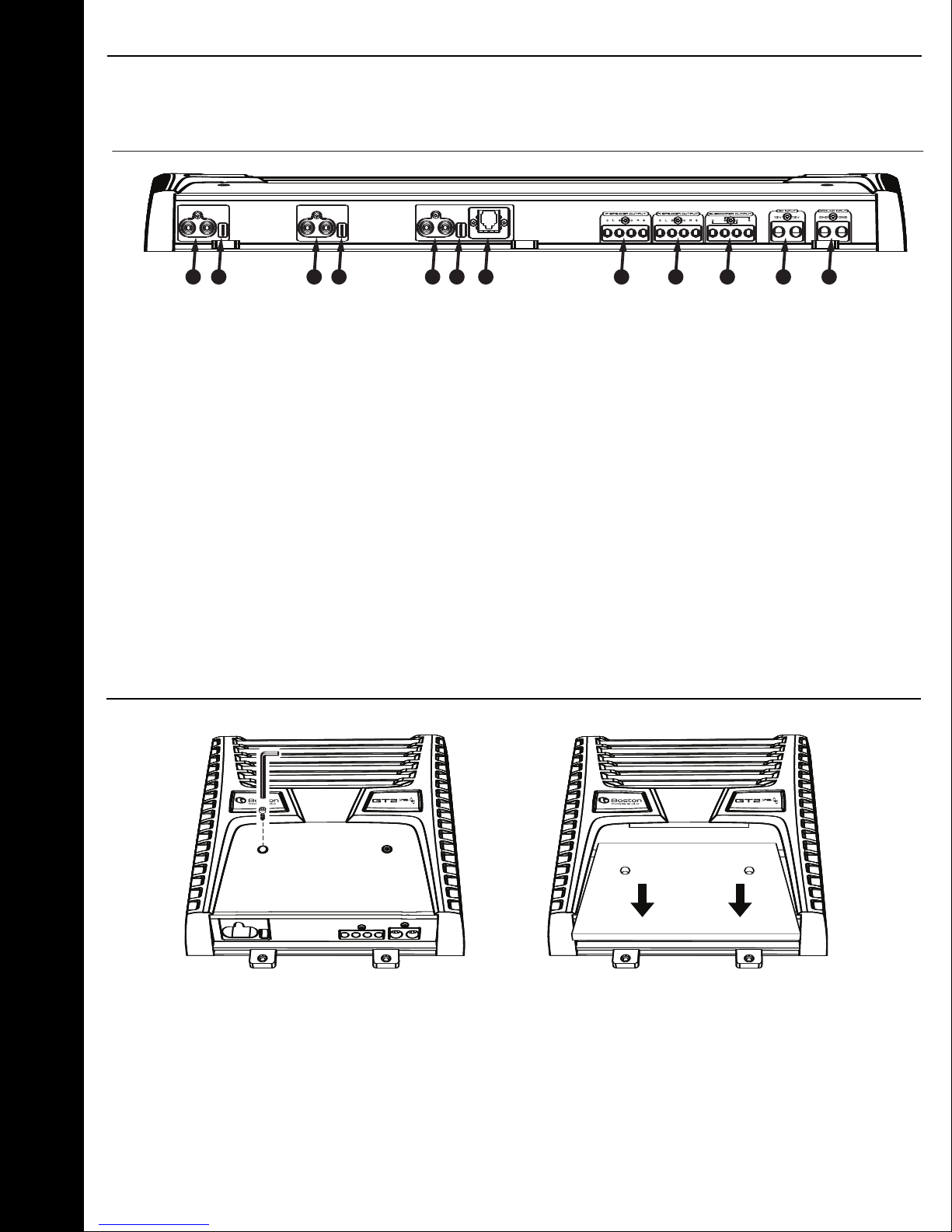
Connections
Connections
u Front Channel RCA Input
v Remote Turn-On (female spade connector supplied)
w Rear Channel RCA Input
x Subwoofer Channel RCA Input
y Remote Gain Port (refer to GT-RSL manual for installation instruction)
z Front Left & Right Speaker Outputs (12-gauge accepted)
{ Rear Left & Right Speaker Outputs (12-gauge accepted)
| Subwoofer Mono Speaker Outputs (12-gauge accepted)
} 12v Power Input (4-gauge accepted)
~ Ground Wire Inputs (4-gauge accepted)
Top Panel Removal / Installation
The cover panel is secured with two (2) 3mm screws. Once unscrewed, pull panel forward,
once clear of the corners of the end panels, it will lift off. Reverse to reinstall.
4
 Loading...