

Page 1
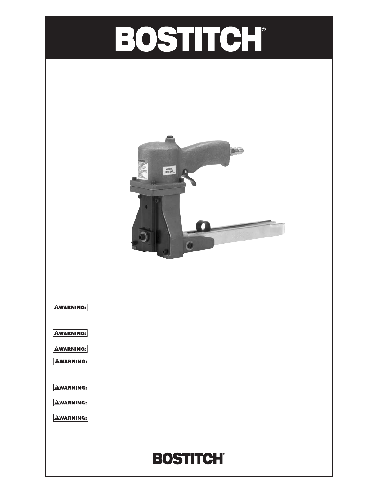
D16-2AD
BOXLOK STAPLER
STAPLE SIZES: SW7437 7/16 SW7437 5/8 SW7437 3/4
SW9040 5/8 SW9040 3/4 SW9040 7/8
Stanley Fastening Systems
BEFORE OPERATING THIS TOOL, ALL OPERATORS SHOULD STUDY THIS MANUAL TO UNDERSTAND
AND FOLLOW THE SAFETY WARNINGS AND INSTRUCTIONS. KEEP THESE INSTRUCTIONS WITH
THE TOOL FOR FUTURE REFERENCE. IF YOU HAVE ANY QUESTIONS, CONTACT YOUR BOSTITCH
REPRESENTATIVE OR DISTRIBUTOR.
DO NOT USE SUPPLY SOURCES WHICH CAN POTENTIALLY EXCEED 80 PSIG (5.7 KG/CM2) AS TOOL
MAY BURST, POSSIBLY CAUSING INJURY.
WHEN AIR SUPPLY .IS CONNECTED KEEP HANDS AND BODY AWAY FROM STAPLE DISCHARGE AREA
AT ALL TIMES. DO NOT FIRE THE TOOL WITHOUT STAPLING INTO MATERIAL.
THE CONNECTOR ON THE TOOL MUST NOT HOLD PRESSURE WHEN AIR SUPPLY IS
DISCONNECTED. IF A WRONG FITTING IS USED, THE TOOL CAN REMAIN CHARGED WITH AIR
AFTER DISCONNECTING AND THUS WILL BE ABLE TO DRIVE A STAPLE EVEN AFTER THE AIR LINE
IS DISCONNECTED POSSIBLY CAUSING INJURY.
DO NOT PULL TRIGGER OR DEPRESS CONTACT ARM WHILE CONNECTED TO THE AIR SUPPLY AS
THE TOOL MAY CYCLE, POSSIBLY CAUSING INJURY.
DO NOT USE OXYGEN, COMBUSTIBLE GASES, OR BOTTLED GASES AS A POWER SOURCE FOR THIS
TOOL AS TOOL MAY EXPLODE, POSSIBLY CAUSING INJURY.
FAILURE TO OBSERVE ANY OF THESE WARNINGS MAY RESULT IN INJURY.
BSA981SREVE 9/03
OPERATION and MAINTENANCE MANUAL
Page 2
AIR SUPPLY AND CONNECTION
Do not use oxygen, combustible gases, or bottled gases as a power source for this tool as
tool may explode, possibly causing injury.
Do not use supply sources which can potentially exceed 80 P.S.I.G. (5.6 kg/cm
2
) as tool may
burst, possibly causing injury .
The connector on the tool must not hold pressure when air supply is disconnected. If a
wrong fitting is used, the tool can remain charged with air after disconnecting and thus will be
able to drive a staple even after the air line is disconnected possibly causing injury.
Clean, dry air as provided by the proper filter-regulator-lubricator is mandatory for satisfactory operation of the
tool. For proper functioning and lubrication, install this trio unit within 15 feet (4.8 meters) of the tool. Check
periodically for cleanliness and oil usage. Use only Mobil Velocite #10 or equivalent oil. DONOT use a
detergent oil.
OPERATING PRESSURE
40 to 60 p.s.i.g. (2.8 to 4.2 kg/cm2). Select the operating pressure within this range for best fastener
performance.
DO NOT EXCEED THIS RECOMMENDED OPERATING PRESSURE.
All hoses, pipes and pipe fittings must have a 3/8” (9.5 mm) minimum inside diameter. Hose fittings must
have a 9/32” (7.1mm) minimum inside diameter.
AIR CONSUMPTION
Air requirements will vary with operating speed and the type of material to be fastened. Do not use more air
pressure than required for the job. Air pressure in excess of the amount required to provide adequate
fastening wastes compressed air and may result in damage to equipment.
After all air connections are made, check for leaks.
CHOICE OF STAPLE SIZE
When letter “A” on D161 12 clamp is in upper left hand corner refer to below listed chart as a guide for
establishing proper staple leg length and approximate clincher depth setting. NOTE: When D16112 clamp is
rotated 180º and letter “B” appears in the upper left hand corner the range of clincher depth settings is
lowered 1/32” (.79mm).
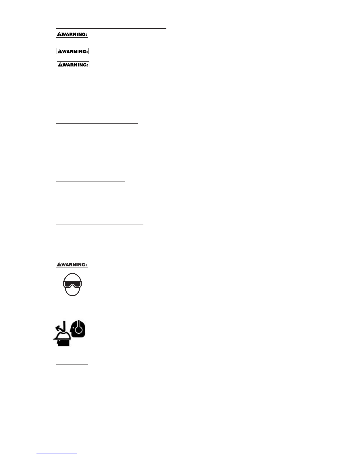
EYE PROTECTION WHICH CONFORMS TO ANSI SPECIFICATIONS AND PROVIDES
PROTECTION AGAINST FLYING PARTICLES BOTH FROM THE FRONT AND SIDE SHOULD
ALWAYS BE WORN BY THE OPERATOR AND OTHERS IN THE WORK AREA WHEN LOADING,
OPERATING OR SERVICING THIS TOOL. EYE PROTECTION IS REQUIRED TO GUARD AGAINST
FLYING FASTENERS AND DEBRIS, WHICH COULD CAUSE SEVERE EYE INJURY.
THE EMPLOYER AND/OR USER MUST ENSURE THAT PROPER EYE PROTECTION IS WORN.
EYE PROTECTION EQUIPMENT MUST CONFORM TO THE REQUIREMENTS OF THE AMERICAN
NATIONAL STANDARDS INSTITUTE, ANSI Z87.1 AND PROVIDE BOTH FRONTAL AND SIDE
PROTECTION. NOTE: NON-SIDE SHIELDED SPECTACLES AND FACE SHIELDS ALONE DO NOT
PROVIDE ADEQUATE PROTECTION.
CAUTION: ADDITIONAL SAFETY PROTECTION WILL BE REQUIRED IN SOME ENVIRONMENTS.
FOR EXAMPLE, THE WORKING AREA MAY INCLUDE EXPOSURE TO NOISE LEVEL WHICH CAN
LEAD TO HEARING DAMAGE. THE EMPLOYER AND USER MUST ENSURE THAT ANY
NECESSARY HEARING PROTECTION IS PROVIDED AND USED BY THE OPERATOR AND
OTHERS IN THE WORK AREA. SOME ENVIRONMENTS WILL REQUIRE THE USE OF HEAD
PROTECTION EQUIPMENT. WHEN REQUIRED, THE EMPLOYER AND USER MUST ENSURE
THAT HEAD PROTECTION CONFORMING TO ANSI Z89. IS USED.
TO LOAD
When loading tool: 1.) Never place a hand or any part of body in fastener discharge area of tool;
2.) Never point tool at anyone; 3.) Do not pull the trigger or depress the trip as accidental
actuation may occur, possibly causing injury.
Pull Pusher to back of magazine and turn over rear as far as it will go.
Place 2 sticks of SW7437 or SW9040 staples in channel.
Swing pusher into place against staples. Do not let it slip and strike staples. This may deform some staples, and
cause poor feeding.
Page 3

TO PREVENT ACCIDENTAL INJURIES:
• Never place a hand or any other part of the body in staple discharge area of
tool while the air supply is connected.
• Never point the tool at anyone else.
• Never engage in horseplay.
• Never pull the trigger unless nose is directed at the work.
• Always handle the tool with care.
• Do not pull the trigger while loading the tool.
TO OPERATE
SHUT OFF AIR SUPPL Y BEFORE MAKING ADJUSTMENT ,REMOVING CLOGGED ST APLES OR SER VICING.
To operate machine, grasp handle. Position machine on box placing directly over the seam between flaps and
in line with desired staple location. Squeeze trigger and release completely before moving machine. Move
machine to each staple position and repeat. Strongest closure requires end staples close to end of box,
approximately 1” (25.4mm). Be sure staples penetrate inner flaps. Check staple clinching in sample of box
board, such as that being used. Adjustment for depth of penetration is easy and full advantage should be taken.
Clincher adjusting clamp settings as listed in chart are offered only as a guide and may have to be slightly
modified.
MAINTENANCE
Always disconnect air supply: 1.) Before making adjustments; 2.) When servicing the tool;
3.) When clearing a jam; 4.) When tool is not in use; 5.) When moving to a different work
area, as accidental actuation may occur, possibly causing injury.
When working on air tools note the warnings in this manual and use extra care when
evaluating problem tools.
Specify the part number when ordering replacement parts. Do not order by description. Do not wrench, twist or
force parts during servicing, as damage may result.
Check screws periodically for tightness. Observe caution against stripping threads when tightening. When the
tool is disassembled, clean thoroughly. Lubricate all moving parts after cleaning. Apply “Magnalube-G” to Orings. Examine all parts for wear during servicing so that replacement parts can be ordered in advance of
trouble.
LUBRICATION
Frequent, but not excessive, lubrication is required for best performance. Oil added through the air line
connection will lubricate the internal parts. Use BOSTITCH Air Tool Lubricant, Mobil Velocite #10, or
equivalent. Do not use detergent oil or additives as these lubricants will cause accelerated wear to the seals
and bumpers in the tool, resulting in poor tool performance and frequent tool maintenance.
If no airline lubricator is used, add oil during use into the air fitting on the tool once or twice a day. Only a few
drops of oil at a time is necessary. Too much oil will only collect inside the tool and will be noticeable in the
exhaust cycle.
CAUTION: Do not store tools in a cold weather environment to prevent frost or ice formation on the tools
operating valves and mechanisms that could cause tool failure.
NOTE: Some commercial air line drying liquids are harmful to “O”-rings and seals – do not use these low
temperature air dryers without checking compatibility.
FILTER:
Dirt and water in the air supply are major causes of wear in pneumatic tools. Afilter will help to get the best
performance and minimum wear from the tool. The filter must have adequate flow capacity for the specific
installation. The filter has to be kept clean to be effective in providing clean compressed air to the tool.
Consult the manufacturer’s instructions on proper maintenance of your filter. A dirty and clogged filter will
cause a pressure drop which will reduce the tool’s performance.
REGULATOR:
Apressure regulator with an operating pressure of 0 - 125 p.s.i. (0 - 8.79 KG/CM2) is required to control the
operating pressure for safe operation of this tool. Do not connect this tool to air pressure which can potentially
exceed 200 p.s.i. (14 KG/CM2)as tool may fracture or burst, possibly causing injury.
Page 4

1. Apply LOCTITE 242 to screw thread before
assembling hanger to tool.
2. Use a swivel type hook on the counterbalance
used to suspend this tool.
VALVE
ASSEMBLY
D60064A
SEE VIEW “A”
ITEM PART NO. DESCRIPTION
NO.
1. 121830 Cylinder
2. D16243 Cylinder Gasket
3. T20111 Trigger
4. T20018 Trigger Pivot Pin
5. T20049 Trigger Pin Retaining Ring
6. D16163A Frame
7. 85014 “O” Ring
8. D16168 Driver Guide L.H.
9. D16167 Driver Guide R.H.
10. D16179 Driver Block
13. UA4006.2 Driver Retaining Screw
14. D16327 Retaining Screw Spacer
15. D16180 Piston Rod
16. 85012 “O” Ring
17. D16185 Driver Block Pin
18. D14227B Piston
19. D16146 Piston Washer
20. 85016 “O” Ring
21. D16183 Escapement Roller
22. D16184A Clincher Link Plate
23. D14130 Clincher Link
24. D14132A Clincher Lever L.H.
25. D14133A Clincher Lever R.H.
ITEM PART NO. DESCRIPTION
NO.
26. D16111A Clincher Adj. Plate
27. D16112 Clincher Adj. Clamp
28. D16114 Front Plate
32. D16149A Pusher Assembly
34. UA4814.1 1/4-20 x 7/8 Soc. Hd.
Cap Screw
35. LW14.2 1/4 Lock Washer
36. UA9607 1/4 Pipe Plug
37. UA4816.12 1/4-20 x 1” Cone Pt.
Set Screw
38. HN1420.2 1/4-20 Hex Jam Nut
39. UA2810 #8-32 x 5/8” Soc. Hd.
Cap Screw
40. LW8 #8 Lock Washer
41. HN3824.4 3/8-24 Elastic Stop Nut
42. UA2808.1 #8-32 x 1/2” Soc. Hd.
Cap Screw
43. LW8 #8 Lock Washer
44. PW516.4 Washer
45. UA5812.3 5/16-18 x 3/4” Soc. Hd.
Cap Screw
46. UA 3808.8 #10-24 x 1/2” Soc. Hd.
Cap Screw
VIEW “A”
54
55
56
57
Page 5

ITEM PART NO. DESCRIPTION
NO.
47. LW10 #10 Lock Washer
48. UP2912.3 3/32 x 3/4” Cotter Pin
49. D14164 Pusher Spring
50. UB2814.2 Pin, Spring .094 x .88
51. D60054 Spring, Valve
ITEM PART NO. DESCRIPTION
NO.
52. D60009 Valve Stem
53. 851201 O-Ring .301 x .070
54. D60008 Valve Body
55. 86458 O-Ring 1/16”x 1/2” ID
56. 86998 O-Ring 1/16”x 9/16” ID
57. 86459 O-Ring 1/16”x 5/8” ID
VARIABLE PARTS
ITEM NO. DESCRIPTION STANDARD PARTS OPTIONAL PARTS
11. Driver D16170 (long) D16178 (short)
30. Clincher D16124 (deep) D16124B (deep pointed)
D14135 (shallow)
33. C’ Balance Hanger D16106A
29. Magazine Assembly D16169A D16164A
[5/8” (15.9mm) [7/16” (11.1mm)
3/4” (19.1mm) 5/8” (15.9mm)
and 7/8” (22.2mm) and 3/4” (19.1mm)
staples] staples]
D14135 clinchers are for shallow penetration as in single
wall board and will clinch inside board without damage to
contents. D16124 clinchers are for deep penetration as in
double wall board.
CAUTION:
WHEN USING DEEP PENETRATION
CLINCHERS, IT MAY BE NECESSARY TO USE A
FILLER TO PREVENT DAMAGE TO
MERCHANDISE. D16124 CLINCHERS MAY ALSO
BE USED FOR STAPLING THROUGH SINGLE
WALL BOARD PROVIDED A FILLER IS USED TO
PREVENT DAMAGE TO CONTENTS OR
CLINCHERS.
To obtain maximum efficiency from the staple
closure, it is important that the staple be clinched properly.
Proper clinching for any thickness board may be obtained by
adjusting the clincher setting with staples of proper leg length.
Use the proper length staples for the thickness of work to be
stapled, otherwise unnecessary pressure is exerted and
staple crowns and legs will be distorted, or the clinch will be
too loose.
CLINCHER ADJUSTMENT:
Clincher adjustment for depth of penetration is obtained by
loosening the clincher adjusting clamp screw on front of
machine and moving it up or down. When in its highest
position, the clinchers are set for the shallowest staple
penetration. Lowering the clinchers increases the
penetration. After establishing the setting, tighten
adjustment screw.
NOTE: The D16-2AD is equipped with a driver to
countersink the crown of the staple below the surface of
the box. The shorter driver, available on order , will allow the
crown of the staple to rest on the top of the box.
Staple driven completely through two
thicknesses of corrugated board and clinched on
underside.
Staple clinched “blind” when desired, in two
thicknesses of corrugated board.
D14135 CLINCHERS
Approx. Clincher Adjusting
Clamp Setting 6 5 4 3 2 1
5/8”
(2) A Board-Blind (15.9mm)
Leg
3/4”
(2) A Board-Through (19.1mm)
Leg
7/16”
(2) B Board-Blind (11.1mm)
Leg
5/8”
(2) B Board-Through (15.9mm)
Leg
7/16”
(2) C Board-Blind (11.1mm)
Leg
5/8”
(2) C Board-Through (15.9mm)
Leg
D16124 DEEP CLINCHERS
Approx. Clincher Adjusting
Clamp Setting 6 5 4 3 2 1
3/4”
(2) A Board-Through (19.1mm)
Leg
3/4”
(2) AB Board-Blind (19.1mm)
Leg
7/8”
(2) AB Board-Through (22.2mm)
Leg
Always disconnect air supply: 1.)
Before making adjustments; 2.)
When servicing the tool; 3.) When
clearing a jam; 4.) When tool is not
in use; 5.) When moving to a
different work area, as accidental
actuation may occur, possibly
causing injury.
When working on air tools note the
warnings in this manual and use
extra care when evaluating problem tools.
Page 6

CLINCHER REPLACEMENT:
1. Loosen the clincher adjusting clamp screw.
2. Slide the clincher adjusting clamp to the highest position. Retighten clamp screw. The clincher screws will be
aligned with and visible through the 2 round holes in the back of the machine frame. Insert a socket screw
wrench to loosen and remove screw holding clincher.
3. Grasp the clinchers by hand or with pliers and lift off the anchor dowels.
4. To assemble new clincher and screw, clean parts thoroughly. Degrease threads with Loctite Safety Solvent
#75559; apply Loctite Grade 222 to screw threads and assemble. Refer to Loctite’s instructions. Tighten
screw firmly .
5. Re-adjust the clincher adjusting clamp to the desired setting and tighten.
DRIVER REPLACEMENT:
1. Remove the magazine.
2. Remove the driver retaining screw, Item 13. Driver may now be removed from the housing.
MAGAZINE REPLACEMENT:
1. Remove staples from magazine.
2. Loosen the two magazine binding screws and nuts.
3. Pull magazine out of engagement with the frame.
4. Insert new magazine making sure the front edge contacts the rear of driver guides. Centralize magazine in
driver guides with binding screws. Tighten the magazine binding screw and nut so that magazine is securely
held.
CAUTION:
DO NOT TIGHTEN THE MAGAZINE BINDING SCREW EXCESSIVELY AS TOO
MUCH PRESSURE WILL DAMAGE THE MAGAZINE.
DRIVER BLOCK PIN REPLACEMENT:
1. Remove piston rod and driver block assembly from machine.
2. Remove as much flare on end of driver block pin as possible.
3. Use a rod smaller than pin diameter as a punch and drive pin free.
4. To reassemble, insert new driver block pin thru driver block and piston rod. Support driver block pin on head
and flare opposite end. Only a slight flare of approx. .020 greater than pin diameter is required to retain pin
and provide proper linear movement of pin in assembly.
Always disconnect air supply: 1.) Before making adjustments; 2.) When
servicing the tool; 3.) When clearing a jam; 4.) When tool is not in use; 5.)
When moving to a different work area, as accidental actuation may occur,
possibly causing injury.
When working on air tools note the warnings in this manual and use extra
care when evaluating problem tools.
Always disconnect air supply: 1.) Before making adjustments; 2.) When servicing the
tool; 3.) When clearing a jam; 4.) When tool is not in use; 5.) When moving to a
different work area, as accidental actuation may occur, possibly causing injury.
When working on air tools note the warnings in this manual and use extra care
when evaluating problem tools.
Always disconnect air supply: 1.) Before making adjustments; 2.) When servicing the
tool; 3.) When clearing a jam; 4.) When tool is not in use; 5.) When moving to a
different work area, as accidental actuation may occur, possibly causing injury.
When working on air tools note the warnings in this manual and use extra care when
evaluating problem tools.
 Loading...