

Bostitch CAP6080WB Operation And Maintenance Manual
BEFORE OPERATING THIS COMPRESSOR, THE USER SHOULD STUDY THIS MANUAL TO UNDERSTAND AND FOLLOW
THE SAFETY WARNINGS AND INSTRUCTIONS. KEEP THESE INSTRUCTIONS WITH THE COMPRESSOR FOR FUTURE
REFERENCE. IF YOU HAVE ANY QUESTIONS, CONTACT YOUR BOSTITCH REPRESENTATIVE OR DISTRIBUTOR.
ANTES DE USAR ESTE COMPRESOR, EL USUARIO DEBE ESTUDIAR ESTE MANUAL PARA ENTENDER Y SEGUIR LAS
ADVERTENCIAS DE SEGURIDAD Y LAS INSTRUCCIONES. CONSERVE ESTAS INSTRUCCIONES CON EL COMPRESOR
PARA REFERENCIA FUTURA. SI TIENE ALGUNA PREGUNTA, DIRÍJASE AL REPRESENTANTE O AL DISTRIBUIDOR.
AVANT D’UTILISER LE COMPRESSEUR, L’UTILISATEUR DOIT LIRE CE MANUEL AFIN DE COMPRENDRE ET DE
RESPECTER LES AVERTISSEMENTS ET CONSIGNES DE SÉCURITÉ. GARDER CES INSTRUCTIONS AVEC LE
COMPRESSEUR POUR RÉFÉRENCE ULTÉRIEURE. POUR DE PLUS AMPLES INFORMATIONS, COMMUNIQUER AVEC
VOTRE REPRÉSENTANT OU DISTRIBUTEUR BOSTITCH.
160182REVB 9/03
OPERATION and MAINTENANCE MANUAL
MANUAL DE OPERACIÓN Y DE MANTENIMIENTO
MANUEL D’OPÉRATION ET DE MAINTENANCE
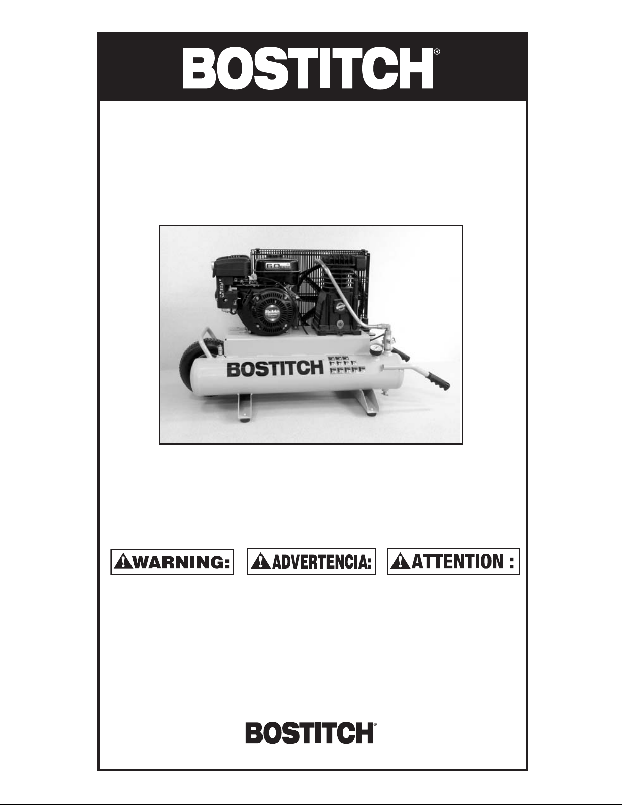
CAP6080WB
AIR COMPRESSOR
COMPRESOR DE AIRE
COMPRESSEUR D’AIR
Stanley Fastening Systems
INTRODUCTION
Congratulations on your purchase of a High Performance BOSTITCH Portable Air Compressor.
This compressor has been designed to provide compressed air to power various pneumatic
tools - including pneumatic fastening tools.
Before assembling, operating or maintaining this air compressor, users must read and
understand the information contained in this owner’s manual. Carefully review the Rules for
Safe Operation section in this owner’s manual and fully understand all warnings.
Danger indicates an imminently hazardous situation which, if not avoided, WILL
result in death or serious injury.
Warnings indicate a potentially hazardous situation which, if not avoided, could
result in death or serious bodily injury.
NOTICE!: Notice indicates important information that if not followed correctly could result in
damage to equipment.
INDEX
Safety Instructions ..........................................................................................................................2
Rules for Safe Operation ..........................................................................................................3, 4
Features...............................................................................................................................................6
Operation Instructions.....................................................................................................................7
General Maintenance .................................................................................................................7, 8
Trouble Shooting guide ...................................................................................................................9
Warranty...........................................................................................................................................10
NOTE:
Bostitch compressors have been engineered to provide excellent customer satisfaction and
are designed to achieve maximum performance.
2
RULES FOR SAFE OPERATION
Be Educated:
All users must read and fully understand all information contained in this owner’s manual
before assembling, operating, or maintaining this air compressor.
Avoid Moving Parts:
When the gas engine is running:
• Never touch any moving parts.
• Keep all body parts, hair, clothing, and jewelry away from moving parts.
• Never operate the air compressor without all guards and shrouds in place.
• Never stand on the compressor.
Attachments and Accessories:
For any attachment or accessory you will be using with this compressor, the maximum
allowable recommended pressure should be clearly marked on the product or should be
clearly noted within the operations manual. Exceeding the pressure rating of these
attachments (including, but not limited to: air tools, air operated accessories, spray guns, air
hose, air hose connections, tires and other inflatables) could cause them to fly apart or
explode and could result in serious injury.
• Never exceed the maximum allowable pressure recommended by the manufacturer of any
attachment or accessory you use with this compressor.
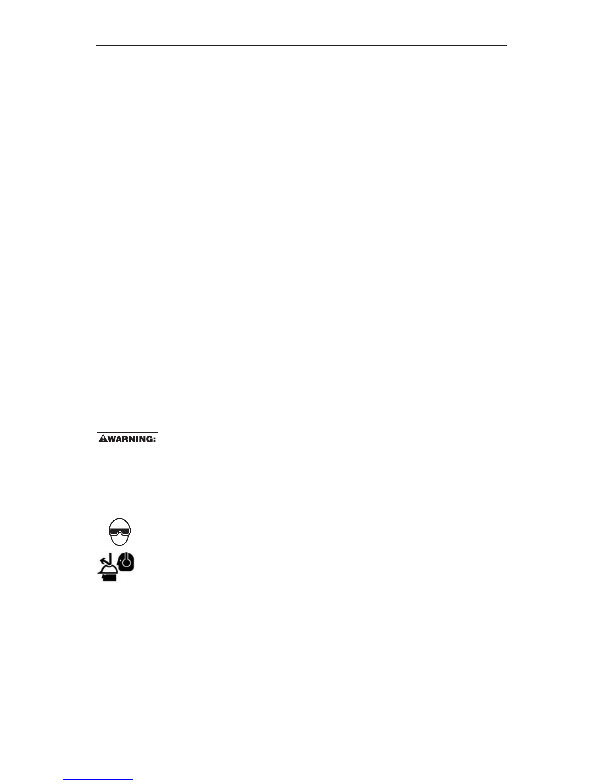
Personal Protection:
The employer and/or user must ensure that proper eye protection is worn. Eye protection
equipment must conform to the requirements of the American National Standards Institute
ANSI Z87.1 and provide both frontal and side protection.
NOTICE!: Non-side shielded spectacles and face shields alone do not provide adequate
protection. Eye protection conforming to ANSI Z87.1 will always be marked “Z87”.
CAUTION: Additional Safety Protection will be required in some environments. For
example, the working area may include exposure to noise level which can lead to hearing
damage. The employer and user must ensure that any necessary hearing protection is
provided and used by the operator and others in the work area. Some environments will
require the use of head protection equipment. When required, the employer and user must
ensure that head protection conforming to ANSI Z89.1.
• Always wear eye protection.
•Wear proper hearing and head protection.
• Compressed air blast must never be aimed at anyone. Compressed air can cause
bodily injury and can propel loose particles and small objects at high speed.
• Keep children away from area of operation.
Transporting:
Use the handle to move the compressor. Do not drag or pull the compressor by the power
cord or air hose. Always disconnect the air compressor before transporting.
3

RULES FOR SAFE OPERATION (continued)
Air Tanks:
Due to condensation associated with the process of compressing air, moisture will build up
inside your compressor’s air tank. Drain tanks of moisture daily (See General Maintenance).
Failure to drain moisture from the tanks properly could lead to the formation of rust and
thinning of the steel tank.
WARNING: FAILURE TO REGULARLY DRAIN TANK MAY CAUSE TANK CORROSION AND
RISK OF TANK EXPLOSION, RESULTING IN SERIOUS INJURY. TO AVOID RISK OF TANK
FAILURE DURING USE, DRAIN TANK AFTER EACH USE OR EVERY FOUR HOURS OF
OPERATION TO PREVENT CONDENSATION BUILD-UP AND TANK CORROSION.
WARNING: DO NOT PERFORM WELDING OR REPAIR OPERATIONS ON THE AIR TANK OF
THIS COMPRESSOR. WELDING ON THE AIR COMPRESSOR TANK CAN SEVERELY IMPAIR
TANK STRENGTH AND CAUSE AN EXTREMELY HAZARDOUS CONDITION. WELDING ON
THE TANK IN ANY MANNER WILL VOID THE WARRANTY.
Ventilation:
WARNING: RISK OF FIRE OR EXPLOSION - DO NOT SPRAY FLAMMABLE LIQUID IN A
CONFINED AREA. SPRAY AREA MUST BE WELL VENTILATED. DO NOT SMOKE WHILE
SPRAYING AND DO NOT SPRAY WHERE SPARK OR FLAME IS PRESENT. KEEP
COMPRESSORS AS FAR FROM SPRAYING AREA AS POSSIBLE.
Risk of Burns:
All air compressors generate heat, even operating under normal conditions.
• To avoid serious burns, never touch the cylinder head parts or tubing during or immediately
after operation.
Safety Valve:
This compressor is equipped with a safety valve that is set to avoid over-pressurization of the
air tanks. This valve is factory pre-set at 140 PSI and will not function unless tank pressure
reaches this pressure. DO NOT ATTEMPT TO ADJUST OR ELIMINATE THIS SAFETY DEVICE.
ANY ADJUSTMENTS TO THIS VALVE COULD CAUSE SERIOUS INJURY. If this device
requires service or maintenance, see an Authorized BOSTITCH Service Center.
DUTY CYCLE:
To ensure long life of your BOSTITCH air compressor, do not operate on more than a 50% duty
cycle. If this air compressor pumps air more than 50% of one hour, then the compressor’s
capability is less than the air delivery required by the application. Always match the air
volume requirements of the attachment or accessory with the air volume delivery of the
compressor.
4

5
CAP6080WB SPECIFICATIONS
Motor: 6HP
Operating Pressure: 0 — 135 PSI
Safety Valve Setting: 150 PSI
Displacement:
Air Delivery: 14.6 CFM @ 40 PSI
13.4 CFM @ 90 PSI
Tank Size: 8 Gallons
Air Outlet: (2) 1/4 - 18 NPT Threaded
Discharge Ports
Pressure Switch Settings: On @ 105 PSI
Off @ 135 PSI
Weight: 145 lbs.
PSI=Pounds Per Square Inch CFM=Cubic Feet Per Minute
FEATURES OF THE BOSTITCH CAP6080WB
A. Tank Pressure Gauge: The
tank pressure gauge indicates
the air pressure that is present in
the tank in PSI (lbs/sq. in.).
B. Regulated Pressure Gauge:
The regulated pressure gauge
indicates the amount of pressure
that is allowed into the two
discharge lines (E) according to
the setting of the regulator.
C. Regulator Knob: The regulator
knob is used to adjust the air
pressure that is available at the
two discharge lines. The
discharge air pressure is increased by turning the knob clockwise and decreased by turning
the knob counter clockwise.
D. Discharge Ports: This compressor is equipped with two discharge ports. These ports are
below the regulated pressure guage and are machined with a 1/4-18 NPT thread to allow the
end user to attach the appropriate style fitting for the application.
E. Drain Cocks: Twist style valves that drain moisture from the tanks when they are opened.
F. Oil Drain Plug: By removing the oil drain plug, oil can be drained from the compressor
crankcase.
G. Oil Fill Plug: Turn counter clockwise to remove
prior to adding oil.
H. Oil Fill Tube: When adding oil to the unit, it is
poured into this opening. The opening is designed
to act as a funnel to make filling easier and cleaner.
I. Sight Glass: See-through so that the user can
quickly and easily verify the oil level prior to
operation.
J. Pet Cock: Twist style valve used for cold starting
or if system is under pressure.
6
A
B
C
D
E
G
H
I
F
J

OPERATION INSTRUCTIONS
Pre-Start Procedures:
1. Inspect the compressor for any damaged components. Do not operate if compressor is
damaged.
2. Check oil level in the compressor pump (See “Checking Oil Level”).
3. Verify that the tanks have been drained and are clear of any moisture or dirt (See
“Draining Tank”).
4. Verify that the air filter is securely in place (See “Air Filter Installation”).
5. Consult gasoline engine manual for proper pre-start procedure.
Start-Up Procedures:
1. Turn red engine “On/Off” switch to “On” position.
2. Push engine Fuel Valve down to open.
3. Push engine Choke lever to left.
4. Open Compressor “Pet Cock” by turning counter clockwise (Located at lower end of
copper feeder tubing.)
5. Start engine by pulling starter handle and returning slowly.
6. Gradually push engine Choke lever to the right.
7. One engine has warmed, close compressor “Pet Cock” and system will pressurize.
Compressor should build pressure to 135 PSI and then slow to idle. If pressure exceeds the
135 PSI max. pressure immediately shutoff and contact a service center.
Shut-Off Procedures:
1. Gasoline engine may be stopped by either turning the “On/Off” switch to stop or by pulling
engine Fuel Valve up to close. Consult the gasoline engine manual for details.
GENERAL MAINTENANCE
Service and Maintenance:
Prior to performing service and maintenance to the compressor, always disconnect all
accessories and attachments from the unit and shut off gasoline engine. When replacing
parts, only use Genuine BOSTITCH replacement parts.
Checking the pump Oil Level :
1. Verify that the compressor is turned off and on a level surface.
2. Observe the oil level through the clear sight glass that is located at the base
of the crankcase.
3. If oil is visible to the middle of the sight glass, then the oil level is acceptable.
Changing the Oil: Oil should be changed every 3 months or 300 hours of operation.
1. Verify the compressor is turned Off.
2. Place a small catch basin under the oil drain port (an 8oz. cup will work fine).
3. Remove the oil fill plug.
4. Remove the oil drain plug.
5. Allow the oil to drain into the catch basin - tilting the compressor toward the
drain plug is beneficial.
6. Insert the oil drain plug into the oil drain port.
7. Add 7.5 oz of SAE 40 weight non detergent oil to the crankcase.
8. Insert oil fill plug.
7

GENERAL MAINTENANCE (continued)
Draining Tanks - Twist-Style Drain Cocks:
1. Verify that the compressor is turned Off.
2. Holding the handle, tilt the compressor toward the drain cocks so that they are positioned
at the bottom of the tank.
3. Turn the drain cocks counter-clockwise to open the valve.
4. Keep the compressor tilted until all moisture has been removed.
5. Turn the drain cocks clockwise to close.
Checking/Cleaning the Air Filter:
WARNING: COOLING FINS, PUMP HEAD, AND SURROUNDING PARTS ARE VERY HOT. DO
NOT TOUCH.
1. Verify that the compressor is turned Off.
2. Remove the 2 screws on face of filter assembly.
3. Remove the filter element from the filter housing.
4. Clean filter pad with soap and water as necessary. If the filter becomes clogged or
damaged, replace filter assembly.
WARNING: NEVER CLEAN AIR FILTER WITH A FLAMMABLE LIQUID OR SOLVENT.
EXPLOSIVE VAPORS MAY ACCUMULATE IN THE AIR TANKS AND CAUSE AN EXPLOSION,
RESULTING IN SERIOUS INJURY OR DEATH.
5. Insert filter element into the cap.
6. Re-assemble filter assembly to pump.
Consult gasoline engine manual for general maintenance procedures.
ANY OTHER SERVICE SHOULD ONLY BE PERFORMED BY AN AUTHORIZED
BOSTITCH SERVICE CENTER
8

TROUBLE SHOOTING GUIDE
NOTE: REMOVE POWER SOURCE AND DRAIN TANK PRESSURE PRIOR TO MAKING ANY REPAIRS OR ADJUSTMENTS.
Problem Probable Cause Correction
Gasoline engine will Cold weather conditions Check pressure switch and verify that it is in the Auto position.
not start (typically temperatures below freezing)
Place compressor in warmer environment for at least 30 minutes
then try restarting.
Consult gasoline engine manual for troubleshooting.
Air leaks at fittings Fittings loose Tighten fitting. Check with soapy water. DO NOT OVER TIGHTEN.
Air leak at pressure switch Clogged check valve Remove and clean check valve
Unit will not build pressure Application requires excessive air demand Reduce demand on compressor
Loose head Tighten bolts on head
Blown gasket Remove head and check for
broken or deformed gasket. Replace if needed.
Unit will not build pressure Worn or broken valves Remove head and replace valves.
Air leak at tank or air tank Damaged air tank
welds. WARNING: DO NOT DRILL INTO , WELD OR OTHERWISE MODIFY AIR TANK.
DAMAGED OR MODIFIED TANKS CAN RUPTURE. REPLACE TANK IMMEDIATELY.
9
 Loading...