

Page 1
70101339 13/06
BOSTITCH AIR TOOL SYSTEMS
BEFORE OPERATING THIS TOOL, ALL OPERATORS SHOULD STUDY THIS
MANUAL TO UNDERSTAND AND FOLLOW THE SAFETY WARNINGS AND
INSTRUCTIONS. KEEP THESE INSTRUCTIONS WITH THE TOOL FOR FUTURE
REFERENCE. IF YOU HAVE ANY QUESTIONS, CONTACT YOUR STANLEYBOSTITCH REPRESENTATIVE OR DISTRIBUTOR.
ANTES DE OPERAR ESTA HERRAMIENTA, TODOS LOS OPERADORES
DEBERÁN ESTUDIAR ESTE MANUAL PARA PODER COMPRENDER Y
SEGUIR LAS ADVERTENCIAS SOBRE SEGURIDAD Y LAS INSTRUCCIONES.
MANTENGA ESTAS INSTRUCCIONES CON LA HERRAMIENTA PARA
FUTURA REFERENCIA, SI TIENE ALGUNA DUDA, COMUNÍQUESE CON SU
REPRESENTANTE DE STANLEY-BOSTITCH O CON SU DISTRIBUIDOR.
LIRE ATTENTIVEMENT LE PRÉSENT MANUEL AVANT D’UTILISER L’APPAREIL.
PRÉTER UNE ATTENTION TOUTE PARTICULIÈRE AUX CONSIGNES DE
SÉCURITÉ ET AUX AVERTISSEMENTS. GARDER CE MANUEL AVEC L’OUTIL
POUR FUTUR RÉFÉRENCE. SI VOUS AVEZ DES QUESTIONS, CONTACTEZ
VOTRE REPRÉSENTANT OU VOTRE CONCESSIONNAIRE STANLEY-BOSTITCH.
OPERATION AND MAINTENANCE MANUAL
MANUAL DE OPERACIÓN Y DE MANTENIMIENTO
MANUEL D’INSTRUCTIONS ET D’ENTRETIEN
BTMT72393
GRAVITY FEED HVLP SPRAY GUN
PISTOLA ASPERSORA DE ALIMENTACIÓN POR
GRAVEDAD DE ALTO VOLUMEN Y BAJA PRESIÓN (HVLP)
PISTOLET HVP À GRAVITATION
Page 2
INTRODUCTION
• Fastworking speed and wide fan pattern.
• High transfer efcency means reduced spray mist.
• Stainless steel needle and uid tip allow use with Water borne materials.
• Maximum Operating Pressure: 50 psi
• High efciency design signicantly reduces operating costs.
INDEX
3 Year Limited Warranty .............................................................2
Tool Components, Tool Specications......................................3
Important Safety Instructions ................................................... 4
Warning ...................................................................................... 5
Installation .................................................................................. 6
Operation ....................................................................................7
Maintenance ...............................................................................8
Trouble Shooting Guide ............................................................ 9-10
IMPORTANT
Please make certain that person who is to use this equipment carefully reads and understands these
instructions before operating.
3 YEAR LIMITED WARRANTY — U.S. and Canada Only
Stanley warrants this product to the original purchaser for a period of
THREE (3) YEARS
against
deciencies in material and workmanship.
This LIMITED WARRANTY
does not cover products that are
improperly used, abused, altered or repaired. Decient products will be replaced or repaired at Stanley's
option. Please call 1-800-505-4648 for more information or return instructions.
THIS LIMITED WARRANTY IS GIVEN IN LIEU OF ALL OTHERS INCLUDING THE IMPLIED WARRANTY OF
MERCHANTABILITY AND FITNESS FOR A PARTICULAR PURPOSE AND EXCLUDES ALL INCIDENTAL OR
CONSEQUENTIAL DAMAGES.
Some states do not allow limitations on how long an implied warranty
lasts or the exclusion or limitation of incidental or consequential damages, so these limitations may not
apply to you. This
LIMITED WARRANTY
gives you specic legal rights that may vary from state to state.
SAFETY GUIDELINES - DEFINITIONS
This manual contains information that is important for you to know and understand. This information
relates to protecting
YOUR SAFETY
and
PREVENTING EQUIPMENT PROBLEMS
. To help you recognize this
information, we use the symbols below. Please read the manual and pay attention to these sections.
SAFETY
and
PREVENTING EQUIPMENT PROBLEMS
.To help you recognize this information, we
use the symbols below. Please read the manual and pay attention to these sections.
Indicates an imminently
hazardous situation which,
if not avoided,
will
result in
death or serious
injury
.
Indicates a potentially
hazardous situation which,
if not avoided,
may
result in
minor or
moderate injury
.
Indicates a potentially
hazardous situation which,
if not avoided,
could
result in
death or serious injury
.
Used without the
safety alert symbol indicates a
potentially hazardous situation which,
if not avoided,
may
result in
property damage
.
- 2 -
Page 3
- 3 -
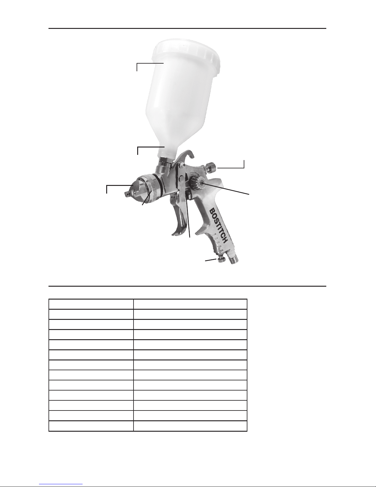
FIG.1
TOOL COMPONENTS
BTMT72393
Description
Gravity Feed Hvlp Spray Gun
Average Air Consumption
5.6CFM 100% Usage
Fluid output
170cc/min
Air Inlet
1/4" NPS (F)
Weight
0.7095KG (1.56lbs)
Min. Hose Size
3/8" ID
Required PSI
30-50 psi
Fluid inlet
3/8" NPS
Inlet Air Pressure
50 psi
Pattern Width
> 180mm
Nozzle Tip
1.5mm
Air connection
1/4'NPT (M)
Air Valve Nut
Fluid Control
Knob
Air Volume Control
Knob
Spray Pattern
Adjustment
Non-Drip Cup
TOOL SPECIFICATIONS
All dimensions in inches unless otherwise specified.
Material Filter
Horns
Air Cap
Page 4
- 4 -
Definitions: Safety Guidelines
The definitions below describe the level of severity
for each signal word. Please read the manual and pay
attention to these symbols.
DANGER: Indicates an imminently hazardous
situation which, if not avoided, will result in death or
serious injury.
WARNING: Indicates a potentially hazardous
situation which, if not avoided, could result in death
or serious injury.
CAUTION: Indicates a potentially hazardous
situation which, if not avoided, may result in minor
or moderate injury.
CAUTION: Used without the safety alert symbol indi-
cates a potentially hazardous situation which, if not
avoided, may result in property damage.
IMPORTANT SAFETY INSTRUCTIONS
Some dust created by power
sanding, sawing, grinding, drilling,
and other construction activities contains chemicals
known to the State of California to cause cancer,
birth defects or other reproductive harm. Some
example of these chemicals are:
• Lead from lead-based paints
• Crystalline silica from bricks and cement
and other masonry products
• Arsenic and chromium from chemically-treated
lumber
Your risk from these exposures varies, depending on
how often you do this type of work. To reduce your
exposure to these chemicals: work in a well ventilated area, and work with approved safety equipment,
al ways wear
OSHA/MSHA/NIOSH
approved,
properly fit ting face mask or res pi ra tor when us ing
such tools.When using air tools, basic safety precautions should always be followed to reduce the risk of
personal injury.
This product contains chemicals,
known to the State of California to cause cancer,
and birth defects or other reproductive harm. Wash
hands after handling.
SAVE THESE INSTRUCTIONS
Improper operation or maintenance of
this product could result in serious injury
and property damage. Read and
understand all warnings and operating
instructions before using this equipment.
When using air tools, basic safety precautions
should always be followed to reduce the risk of
personal injury.
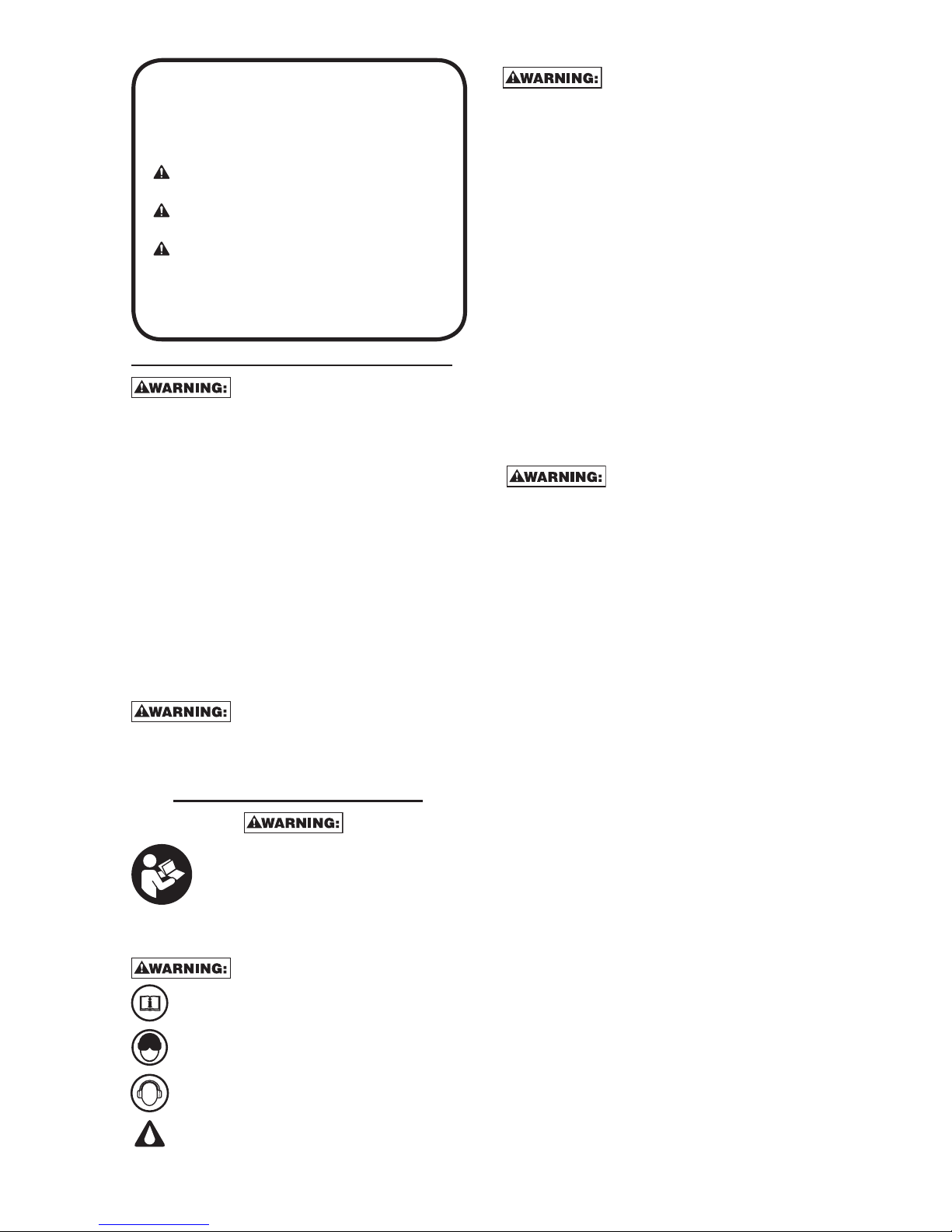
Read and understand this instruction manual
and tool labels before installing, operating or
servicing this tool. Keep these instructions in
a safe accessible place.
Operators and others in work area must wear
ANSI Z87.1 CAN/CSA Z94.3 approved safety
glasses with side shields.
Operators and others in work area must wear
ear protection.
Oil daily for optimal performance.
• All persons in the work area must always
wear approved eye and hearing protection
and approved respiratory protection when this
spray gun is in operation.
• Never aim spray gun at anyone. Do not spray
near sparks, open flame, lit cigarettes, pilot
lights, space heaters or any other potential
ignition source, DO NOT SMOKE IN WORK
AREA.
• Only persons well acquainted with these rules
of safe operation should be allowed to use the
air tool .
• Follow manufacturers instructions and safety
information to ensure safe handling and proper
use of paints, laquers, thinners, base coats, etc.
Do not use latex or other heavy paints. They are
not recommended for this spray gun.
• Always keep work area free from obstructions
and well ventiilated.
• Always disconnect spray gun from air source
before disassembly.
• To avoid creating an explosive atmosphere,
work only in well ventilated areas.
• Always use respiratory protection to prevent
inhalation of harmful fumes and materials.
• Before disassembly or removal of any part of
gun or attached components, shut off
compressor, release pressure by depressing
trigger, and disconnect power source. NEVER
assume system pressure is zero!
Page 5
- 5 -
RISK OF EXPLOSION OR FIRE
WHAT CAN HAPPEN HOW TO PREVENT IT
• When paints or
materials are
sprayed, they are
broken into very
small particles and
mi xed with air. This
will cause certain
paints and
materials to
become extremely
flammable and
could result in
serious
injury or death.
• Never spray near
open flames or pilot
lights in stoves or
heaters.
• Never smoke while
spraying.
• Provide ample
ventilation when
spraying indoors.
• 1,1,1-Trichloroethane
and Methylene
Chloride can
chemically react
with the aluminum
used in most spray
equipment, and
this gun and cup,
to produce an
explosion hazard
and could result
in serous injury or
death.
• Read the label or
data sheet for the
material you intend
to spray.
• Never use any type
of spray coating
material containing
these solvents.
• Never use these
solvents for
equipment cleaning
or flushing.
• If in doubt as to
whether a material
is compatible,
contact your
material supplier.
RISK TO BREATHING
(ASPHYXIATION)
WHAT CAN HAPPEN HOW TO PREVENT IT
• Some paints,
coatings and
solvents may cause
lung damage, and
burns if inhaled or
allowed to come
into contact with
skin or eyes.
• Use a NIOSH
approved mask
or respirator and
protective clothing designed for
use with your
specific application
and spray materials. Some masks
provide only limited
protection against
toxic materials and
harmful paint solvent. Consult with
a Safety Expert or
Industrial Hygienist
if uncertain about
your equipment or
materials.
RISK OF CUT OR BURNS
WHAT CAN HAPPEN HOW TO PREVENT IT
• Spray guns
operate at
pressures and
velocities high
enough to
penetrate human
and animal flesh,
which could result
in amputation or
other serious injury.
! See a physician
immediately !
• Never place hands
in front of nozzle.
• Direct spray away
from self and
others.
• Seek immediate
medical attention if
direct spray
contacts
exposed body
parts.
RISK FROM FLYING OBJECTS
WHAT CAN HAPPEN HOW TO PREVENT IT
• Certain parts are
under pressure
whenever the gun
is connected to
a pressurized air
line. These parts
may be propelled
if the gun is disassembled.
• Disconnect the
gun from the air
line, or completely
depressurize the
air line whenever
the gun is to
be disassembled.
• Compressed air
may propel dirt,
metal shavings,
etc. and possibly
cause an injury.
• Never point any
nozzle or sprayer
toward a person or
part of the body.
• Always wear ANSI
Z87.1 CAN/CSA
Z94.3 approved
safety glasses with
side shields.
• Prolonged exposure to air spray
can result in
permanent damage to hearing.
• Always wear hearing protection
when operating
spray equipment.
Page 6
INSTALLATION
AIR SUPPLY
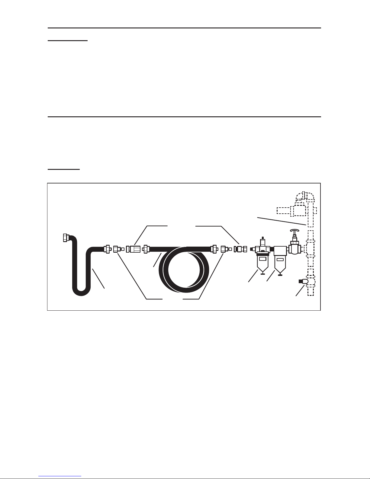
The recommended hook-up is shown in
Figure A.
Pneumatic tools operate on a wide range of air
pressures. For maximum efficiency and longer tool life, the pressure of the air supplied to these tools
MUST
not
exceed the rated PSI at the tool when the tool is running. Using a higher than rated pressure will cause faster
wear and drastically shorten the tool’s life. A higher air pressure can also cause an unsafe condition and explosion. The inside diameter of the hose should be increased to compensate for unusually long air hoses (over 25
feet). Minimum hose diameter should be 3/8” I.D. and fittings should have 1/4” NPT thread. The use of air line
lubricators and air line filters is recommended to prevent water in the line that can damage the tool. Drain the
air tank daily. Clean the air inlet filter screen on at least a weekly schedule to remove accumulated dirt or other
matter that can restrict air flow. The tool’s air inlet used for connecting an air supply has standard 1/4” NPT
American thread.
SAFETY RULES FOR PNEUMATIC TOOLS
1) Inspect the air hose for cracks or other problems. Replace the hose if worn.
2) Never point an air hose at another person.
3) Disconnect the tool when not in use, or before performing service or changing accessories.
4) Use proper hoses and fittings. Never use quick change couplings attached to the tool. Instead, add a hose and
coupling between the tool and the air supply.
FIGURE A
- 6 -
1/2”(or larger)
Pipe and Fittings
Coupler
Air Hose
Leader Hose
Tool
Nipple
Oiler
Filter
Drain Daily
Page 7

OPERATION
DO NOT ATTEMPTTO UNCLOG (BACK
FLUSH) SPRAY GUN BY SQUEEZING
TRIGGER WHILE HOLDING FINGER IN FRONT OF FLUID
NOZZLE.
PRESSURE MAY VARY ACCORDING
TO VISCOSITY OF MATERIAL USED.
MAXIMUM WORKING PRESSURE OF GUN IS 50 PSI.
DO NOT EXCEED PRESSURE LIMIT OF GUN OR ANY
OTHER COMPONENT IN SYSTEM!
PRIOR TO DAILY OPERATION, MAKE
CERTAIN THAT ALL CONNECTIONS
AND FITTINGS ARE SECURE. CHECK HOSE AND ALL
CONNECTIONS FOR A WEAK OR WORN CONDITION
THAT COULD RENDER SYSTEM UNSAFE. ALL
REPLACEMENT COMPONENTS SUCH AS HOSE
OR FITTINGS MUST HAVE A WORKING PRESSURE
EQUAL TO OR GREATER THAN SYSTEM PRESSURE.
Prior to shipment, this gun was treated with an
anticorrosive agent. Before using this gun make sure
that it is carefully ushed with thinner.
1. The position of the air cap
(H) horns
will determine
the spray pattern. Loosen
(G) air cap
and rotate horns
to achieve desired pattern. Tighten air cap.
2. Attach paint cup to the gun.
NOTE:
The
(F) filter
supplied is optional to protect
against contaminants and small particles. See parts
list for lter orientation.
3. Attach air supply line to 1/4 NPS air inlet.
NEVER point spray gun at self or any other person.
Accidental discharge of material may result in serious injury.
4. Adjust air pressure at air compressor.
DO NOT exceed 50 psi.
5. Depress spray gun trigger fully to spray material.
NOTE:
Depressing trigger partially will cause only air to be released.
ADJUST SPRAY GUN:
a. Amount of material released (density of “fan spray”) is controlled
by
(D) fluid
control knob . Turn knob counterclockwise to increase, or
clockwise to decrease, the uid ow.
b. Width of “fan spray” is governed by
(B) spray pattern control knob
. Turn knob counter-clockwise to
increase, or clockwise to decrease, air ow.
c. Air quantity is controlled by
(C) air-volume control knob
. Turn knob counterclockwise to increase, or
clockwise to decrease, the air ow.
NOTE:
Care should be exercised when handling spray gun to avoid damage to the orice of the air cap
and tip of uid nozzle. Damage to these parts results in irregular spray patterns.
- 7 -
(A) Air
Valve Nut
(E) Non-Drip Cup
(G) Air Cap
(C) Air
Volume
Control Knob
(D) Fluid
Control
Knob
(B) Spray
Pattern
Adjustment
(H) Horns
(F) Material
Filter
Horizontal position
Vertical position
Page 8

- 8 -
MAINTENANCE
SHUT OFF AIR COMPRESSOR, RELEASE ALL PRESSURE BY DEPRESSING TRIGGER, AND
DISCONNECT POWER SOURCE BEFORE DISASSEMBLY OR REMOVAL OF ANY PART OF THE GUN OR
ATTACHED COMPONENTS.
ALWAYS EXERCISE EXTREME CARE WHEN USING ANY SOLVENT OR THINNER. NEVER
CLEAN THE GUN NEAR FIRE, FLAME, OR ANY SOURCE OF HEAT OR SPARKS. PROPERLY DISPOSE OF
USED CLEANING MATERIALS.
DO NOT SOAK THE ENTIRE SPRAY GUN IN SOLVENT OR THINNER FOR A LONG PERIOD
OF TIME AS THIS WILL DESTROY LUBRICANTS AND POSSIBLY IMPAIR OPERATION. NEVER USE LYE OR
CAUSTIC ALKALINE SOLUTION FOR CLEANING. SUCH SOLUTIONS WILL ATTACK ALUMINUM ALLOY
PARTS OF THE GUN.
It is important that the spray gun be cleaned after each use.
CLEANING
1. Empty material from gravity feed cup and replace with a suitable solvent or thinner.
2. Operate trigger until all material traces have disappeared and gun is thoroughly clean.
3. Clean air cap with a brush.
4. Wipe the exterior of the spray gun with a solvent soaked cloth or use cleaning brush(es) provided to
remove any accumulated material.
IMPORTANT:
Make certain that the air cap and uid nozzle are kept clean at all times. If necessary, remove
these two components and soak them in solvent. DO NOT use hard objects to clean clogged holes. The
smallest amount of damage may cause
irregular spray pattern.
NOTE:
If the uid nozzle is to be removed for thorough cleaning, squeeze the trigger to prevent damage of
the uid needle tip when unscrewing the nozzle.
LUBRICATION
Lubrication procedures must be observed after thoroughly cleaning the gun to ensure effective, high
quality performance of spray gun.
1. Lubricate working points with straight mineral oil, or castor oil.
2. Periodically, place a few drops of oil on tapered sections of the uid nozzle to ensure easy operation
of the air cap. When spraying water base materials, coat the uid nozzle inside and outside with straight
mineral oil after each use.
3. Outer diameter of the needle sleeve in the uid needle assembly must be lubricated occasionally with
straight mineral oil.
Page 9
- 9 -
TROUBLESHOOTING GUIDE
This section provides a list of the more frequently encountered malfunctions, their cause and corrective
actions. The operator or maintenance personnel can perform some corrective actions, and others may
require the assistance of a qualied Bostitch technician or your dealer.
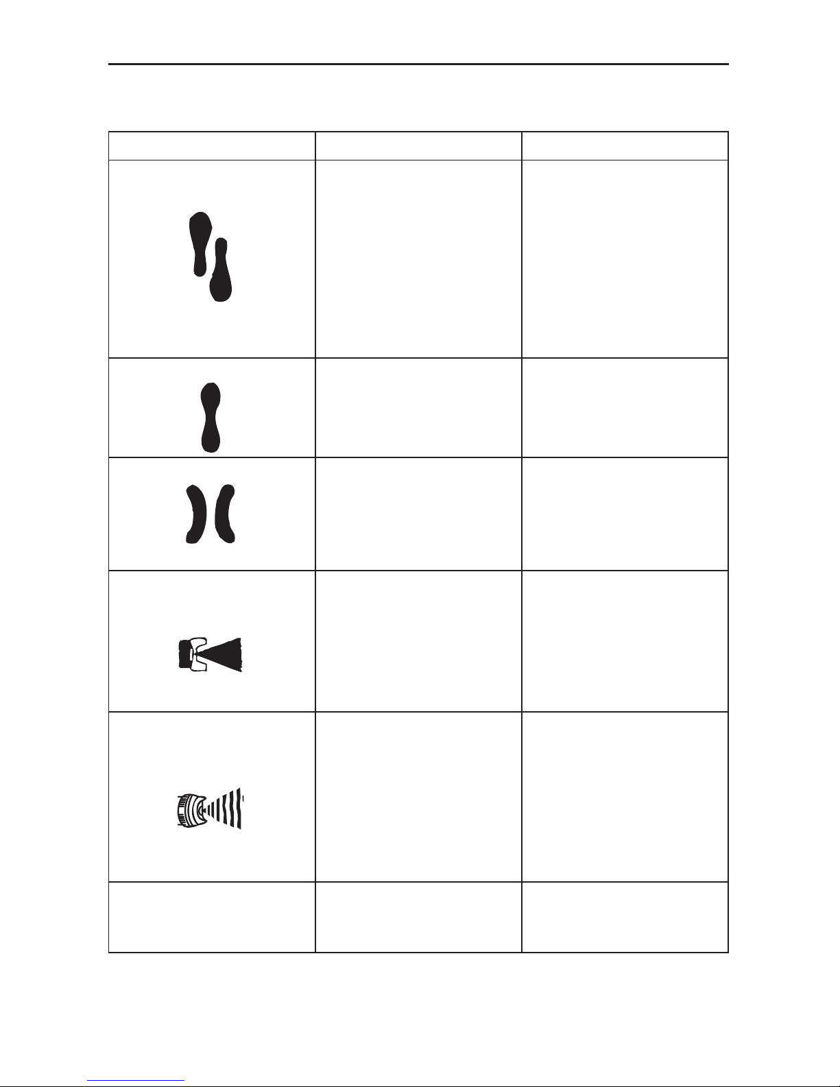
DEFECTIVE PATTERN LIKELY CAUSE SUGGESTED REMEDY
HEAVY TOP OR
BOTTOM PATTERN
1. Dirty or damaged
air cap
2. Dirty or damaged
uid tip
1. Rotate air cap 180°. If the
pattern follows the air cap,
the problem is in the air cap.
Clean and inspect the air cap.
If the pattern is not corrected,
replacement is necessary.
2. If pattern doesn’t follow the
air cap, the problem is with
the uid tip. Clean and
inspect the tip for dried paint,
dirt or damage. If the pattern
is not corrected, replacement
is necessary.
SPLIT PATTERN Air pressure too high for
material viscosity being sprayed.
1. Reduce air pressure.
2. Turn pattern control knob
clockwise to decrease fan
width. Turn uid needle
adjusting nut counterclockwise
to increase uid ow.
1. Dirty or distorted air horn
holes.
2. One of the air horn holes
completely obstructed.
1. Rotate air cap 180°. If the
pattern follows the air cap,
the problem is in the air cap.
2. Clean and inspect the horn
holes. If the horn holes are
distorted, replacement is
necessary.
GUN SPLITTING Air getting into paint stream
somewhere.
Example: Same symptoms as a
cup running out paint.
1. Check and tighten uid needle
packing nut.
2. Tighten uid tip.
3. Check uid tip seat for
damage.
4. Check for poor gun to cup
seating.
5. Check that cup is correctly
fastened on the gun.
SPITTING, IRREQULAR
OR FLUTTERING SPRAY
1. Fluid nozzle
cracked or worn
2. Leak at thread
of uid nozzle
3. Leak at uid needle
4. Needle packing
worn out
5. Insufcient uid in cup
6. Vent hole in
container cover clogged
1. Tighten or replace
2. Tighten uid nozzle
3. Tighten compression nut
assembly or replace needle
packing
4. Replace packing
5. Fill cup with uid
6. Clean out
AIR BACK
PRESSURING
INTO CUP.
Excessive air blowing back into
cup.
1. Tighten uid tip.
2. Check uid tip seat.
3. Check for damaged uid seat
on tip or seat on gun head.
Page 10
- 10 -
TROUBLESHOOTING GUIDE:
This section provides a list of the more frequently encountered malfunctions, their cause and corrective
actions. The operator or maintenance personnel can perform some corrective actions, and others may
require the assistance of a qualied Bostitch technician or your dealer.
DEFECTIVE PATTERN LIKELY CAUSE SUGGESTED REMEDY
UNATOMIZED
OR SPATTERED
SPRAY
1. Material too heavy
2. Insufcient air
pressure
3. Fluid pressure
too high
4. Dried material on tip
of uid nozzle or
air jets of air cap
1. Thin material or use larger
orice uid nozzle set
2. Increase pressure to within
limit
3. Reduce pressure
4. Clean
INADEQUATE
AIR DELIVERY
1. Air needle partially
closed
2. Dried material in air
jets or air cap
3. Obstruction in air line.
1. Open control knob
2. Clean
3. Remove obstruction
EXCESSIVE FOG 1. Air pressure too high
for viscosity of uid
1. Reduce air pressure and/or
open uid control knob
MATERIAL LEAKING
FROM FLUID INLET
OF CUP
1. Loose cup or foreign
substances on/between cup
thread and uid inlet
1. Tighten and clean or replace it
MATERIAL LEAKING
FROM NOZZLE WHEN
TRIGGER IS RELEASED
1. Worn uid neddle
2. Dried material in tip of nozzle
3. Loose packing nut
1. Replace
2. Clean
3. Tighten needle packing nut by
turning counterclockwise
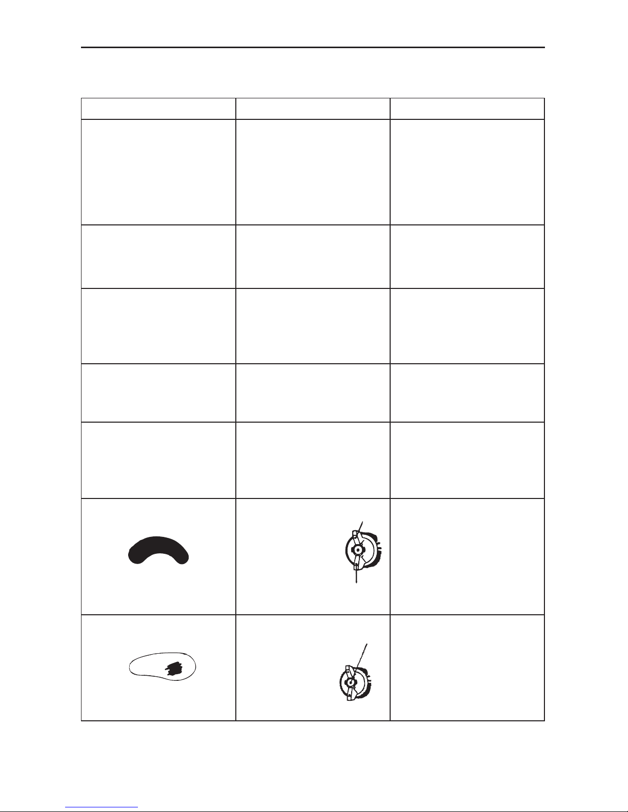
A. Dried material is
clogging side-port “A”
and causing
side-port “B” to blow
spray towards the
clogged side
Soak side-ports in
thinner to clean clog.
DO NOT poke any
opening with hard objects.
B. 1. Dried material at
uid nozzle “C”
restricts air ow
2. Loose air nozzle
3. Air pressure
set too high
1. Remove air nozzle.
Wipe off uid tip using a
cloth soaked in thinner
or by soft brush
2. Fasten nozzle securely
3. Reduce air pressure
A
B
C
Page 11

- 11 -
GLOSSARY
CFM:
Cubic feet per minute.
SCFM:
Standard cubic feet per minute; a unit of measure of air delivery.
PSI:
Pounds per square inch; a unit of measure of pressure.
Code Certification:
Products that bear one or more of the following marks:
UL, CUL, ETL, CETL
, have
been evaluated by
OSHA
certied independent safety laboratories and meet the applicable Underwriters
Laboratories Standards for Safety.
RPM:
Revolutions per minute; is a measure of the frequency of a rotation
BPM:
Beats per minute.
NPT:
National pipe thread (tapered thread); is a U.S. standard for tapered threads used on threaded
pipes and ttings.
ID:
Inner diameter
LAS CAÍDAS PUEDEN CAUSAR
LESIONES GRAVES. NO PISAR NI
PARARSE EN ESTA ÁREA.
ADVERTENCIA
LES CHUTES PEUVENT CAUSER DE GRAVES
BLESSURES. NE MARCHEZ PAS ET NE VOUS
TENEZ PAS SUR CET EMPLACEMENT.
AVERTISSEMENT
FALLS CAN CAUSE SERIOUS
INJURIES. DO NOT STEP OR STAND
ON THIS AREA.
WARNING
SEE OWNER’S MANUAL FOR
BREAK-IN PROCEDURES.
CAUTION
PARA EL PROCEDIMIENTO DE
ASENTADO DE LA MAQUINA, VER
MANUAL DEL OPERARIO.
ATENCIÓN
CONSULTEZ LE MANUEL DE
L’UTILISATEUR POUR LES
PROCEDURES DE RODAGE.
ATTENTION
ADVERTENCIA
EL USO INDEBIDO PUEDE GENERAR RIESGOS. SEGUIR ESTAS INSTRUCCIONES: RIESGO DE ESTALLIDO. ASEGÚRESE QUE LA VÁLVULA DE SALIDA DEL
COMPRESOR ESTE REGULADA POR DEBAJO DEL MÁXIMO DE LA PRESIÓN DE OPERACIÓN DE LA PISTOLA ROCIADORA O HERRAMIENTA. ANTES DE ARRANCAR
EL COMPRESOR, TIRAR DEL ANILLO EN LA VÁLBULA DE SEGURIDAD PARA ASEGURARSE QUE LA VÁLVULA SE MUEVE LIBREMENTE. DRENAR EL AGUA DEL TANQUE DESPUÉS DE CADA USO.
RIESGO DE FUEGO O EXPLOSIÓN. NO ROCIAR LÍQUIDO NI PINTURAS INFLAMABLES O COMBUSTIBLES CERCA DE CHISPAS, LLAMAS, LLAMAS DE PILOTO O EN ÁREAS CERRADAS. EL ÂREA DE
TRABAJO DEBE ESTAR BIEN VENTILADA. MANTENER EL COMPRESOR ALEJADO POR LO MENOS 20 PIES DEL AREA DE PINTURA. NO LLEVAR NI OPERAR EL COMPRESOR NI DISPOSITIVO ELÉCTRICO
ALGUNO CERCA DEL AREA DEL ROCIADO. NUNCA FUME EN EL ÁREA DEL ROCIADO. USAR UNA MANGUERE DE UN MÍNIMO DE 25 PIES PARA CONECTAR LA PISTOLA AL COMPRESOR. RIESGO DE
DAÑOS PERSONALES. USAR GAFAS DE SEGURIDAD ANSI Z87. NUNCA APUNTAR EL CHORRO DE AIRE COMPRIMIDO O DE MATERIAL QUE SE ESTÉ ROCIANDO A SÍ MISMO NI A OTRAS PERSONAS.
NE RESPIRAR EL AIRE COMPRIMIDO. REDUCIR LA PRESIÓN A CERO ANTES DE DESMONTAR LA MANGUERA. RIESGO DE CHOQUE ELÉCTRICO. ALTO VOLTAJE. DESCONECTAR LA UNIDAD ANTES DE
QUITAR LA CUBIERTA. NO EXPONER A LLUVIA. ALMACENAR EN INTERIORES. PARA SEGURIDAD COMPLETA, OPERACIÓN E INSTRUCCIONES PARA REPARAR, LEER EL MANUAL DEL OPERADOR.
AVERTISSEMENT
UNE UTILISATION INCORRECTE PEUT ÊTRE DANGEREUSE. SUIVEZ LES INSTRUCTIONS CI-DESSOUS: RISQUE D'ECLATEMENT. ASSUREZ-VOUS QUE LA
PRESSION DE SORTIE DU COMPRESSEUR EST RÉGLÉE À UN NIVEAU INFÉRIEUR À LA PRESSION D'UTILISATION MAXIMUM DU PISTOLET VAPORISATEUR OU DE
L'ACCESSOIRE. AVANT DE DÉMARRER LE COMPRESSEUR, TIREZ SUR L'ANNEAU DE LA SOUPAPE DE SÛRETÉ POUR VOUS ASSURER QU'ELLE FONCTIONNE LIBREMENT. VIDANGEZ L'EAU DU RÉSERVOIR
À AIR APRÈS CHAQUE UTILISATION. RISQUE D'INCENDIE OU D'EXPLOSION. NE PAS VAPORISER UN LIQUIDE OU UN PEINTURE INFLAMMABLE OU COMBUSTIBLE PRÈS D'ÉTINCELLES, DE FLAMMES, DE
VEILLEUSES NI DANS UN ENDROIT RESTREINT OU RENFERMÉ. L'AIRE DE VAPORISATION DOIT ÊTRE BIEN AÉRÉE. GARDEZ LE COMPRESSEUR À UNE DISTANCE D'AU MOINS 20 PIEDS DE LA SURFACE À
VAPORISER. NE PORTEZ PAS LE COMPRESSEUR ET NE L'UTILISEZ PAS NI AUCUN AUTRE APPAREIL ÉLECTRIQUE À PROXIMITÉ DE L'AIRE DE VAPORISATION. NE FUMEZ JAMAIS QUAND VOUS
VAPORISEZ. UTILISEZ UN FLEXIBLE D'AIR D'UNE LONGUEUR MINIMUM DE 25 PIEDS POUR RELIER LE PISTOLET VAPORISATEUR AU COMPRESSEUR. RISQUE DE BLESSURES CORPORELLES. PORTEZ DES
LUNETTES DE PROTECTION ANSI Z87. NE DIRIGEZ JAMAIS L'AIR COMPRIME OU DES MATÉRIAUX VERS SOI OU VERS AUTRUI. NE JAMAIS UTILISER DE L'AIR COMPRIMÉ POUR LA RESPIRATION. RÉGLEZ
LA PRESSION À ZÉRO AVANT DE RETIRER LE BOYAU. RISQUE DE CHOC ÉLECTRIQUE. VOLTAGE DANGEREUX. DEBRANCHEZ LA MACHINE AVANT D'ENLEVER BOITIER. N'EXPOSEZ PAS LE COMPRESSEUR
À LA PLUIE. REMISEZ-LE À L'INTÉRIEUR. LISEZ LE MANUEL DE L'UTILISATEUR POUR DES INSTRUCTIONS COMPLÈTES CONCERNANT LA SÉCURITÉ, L'UTILISATION ET LES RÉPARATIONS.
INCORRECT USE CAN CAUSE HAZARDS. FOLLOW THESE INSTRUCTIONS: RISK OF BURSTING. MAKE SURE THE COMPRESSOR OUTLET PRESSURE IS SET
LOWER THAN THE MAXIMUM OPERATING PRESSURE OF THE SPRAY GUN OR TOOL. BEFORE STARTING THE COMPRESSOR, PULL THE RING ON THE SAFETY
VALVE TO MAKE SURE THE VALVE MOVES FREELY. DRAIN WATER FROM TANK AFTER EACH USE. RISK OF FIRE OR EXPLOSION. DO NOT SPRAY A FLAMMABLE OR COMBUSTIBLE
LIQUID OR PAINT NEAR SPARKS, FLAMES, PILOT LIGHTS, OR IN A CONFINED AREA. THE SPRAY AREA MUST BE WELL VENTILATED. KEEP COMPRESSOR AT LEAST 20 FEET AWAY FROM
SPRAY AREA. DO NOT CARRY AND OPERATE THE COMPRESSOR, OR ANY OTHER ELECTRICAL DEVICE NEAR THE SPRAY AREA. NEVER SMOKE WHEN SPRAYING. USE A MINIMUM OF
25 FEET OF HOSE TO CONNECT A SPRAY GUN TO THE COMPRESSOR. RISK OF PERSONAL INJURY. WEAR ANSI Z87 SAFETY GLASSES. NEVER SPRAY COMPRESSED AIR OR MATERIAL
AT SELF OR OTHERS. DO NOT USE COMPRESSED AIR FOR BREATHING. REGULATE PRESSURE TO ZERO BEFORE REMOVING HOSE. RISK OF ELECTRICAL SHOCK. HAZARDOUS VOLTAGE.
UNPLUG UNIT BEFORE REMOVING COVER. DO NOT EXPOSE TO RAIN, STORE INDOORS. READ OWNER'S MANUAL FOR COMPLETE SAFETY, OPERATION, AND REPAIR INSTRUCTIONS.
WARNING
HOLD HOSE FIRMLY TO
PREVENT HOSE WHIP.
CAUTION
SOSTENGA LA MANGUERA
CON FIRMEZA PARA EVITAR EL.
ATENCIÓN
BIEN TENIR LE TUYAU POUR
ÉVITER UN À-COUP.
ATTENTION
DRAIN TANK DAILY OR AFTER EACH USE. CONDENSATION BUILD-UP MAY CAUSE CORROSION
INSIDE TANK RESULTING IN TANK FAILURE. SEE MANUAL FOR INSPECTION PROCEDURES. TO DRAIN
TANK OPEN VALVE SLOWLY AND TILT COMPRESSOR TO EMPTY ACCUMULATED WATER.
WARNING
DRENE EL TANQUE A DIARIO O DESPUÉS DE CADA USO. LA ACUMULACIÓN DE CONDENSACIÓN
PUEDE OCASIONAR CORROSIÓN DENTRO DEL TANQUE Y PROVOCAR FALLA DEL TANQUE.
CONSULTE EL MANUAL PARA CONOCER LOS PROCEDIMIENTOS DE INSPECCIÓN. PARA DRENAR EL TANQUE, ABRA LA
VÁLVULA LENTAMENTE E INCLINE EL COMPRESOR PARAELIMINAR EL AGUA ACUMULADA.
ADVERTENCIA
RÉSERVOIR DE VIDANGE QUOTIDIEN
OU APRÈS CHAQUE UTILISATION. L'HABILLAGE
DE
CONDENSATION PEUT CAUSER LA CORROSION À L'INTÉRIEUR DU RÉSERVOIR AYANT POUR
RÉSULTAT L'ÉCHEC DE RÉSERVOIR. VOIR LE MANUEL POUR DES PROCÉDURES D'INSPECTION. À LA VALVE
OUVERTE
DE RÉSERVOIR DE VIDANGE LENTEMENT ET AU COMPRESSEUR D'INCLINAISON À L'EAU ACCUMULÉE VIDE.
AVERTISSEMENT
Page 12

- 12 -
INTRODUCCIÓN
• Velocidad de rápido funcionamiento y modelo de ventilador ancho
• VEcacia de transferencia elevada signica pulverización reducida
• Aguja de acero inoxidable y tapa de uido que permite usar con materiales transportados por agua
• Presión máxima de funcionamiento: 50 psi
• Diseño de ecacia elevada que reduce signicativamente los costos de funcionamiento
ÍNDICE
Garantía Limitada De 3 Años .................................................... 12
Componentes De La Herramienta, Especicaciones De La
Herramienta ................................................................................ 13
Instrucciones De Seguridad ...................................................... 14
Advertencia.................................................................................15
Instalación ..................................................................................16
Operación ................................................................................... 17
Instrucciones De Mantenimiento .............................................. 18
Solución De Problemas ............................................................. 19-20
IMPORTANT
Por favor asegúrese de que la persona que va a usar este equipo lea cuidadosamente y comprenda estas
instrucciones antes de operarlo.
GARANTÍA LIMITADA DE 3 AÑOS
Stanley garantiza este producto al comprador original durante un período de
TRES (3) AÑOS
contra
deficiencias en material y mano de obra. Esta
GARANTÍA LIMITADA
no cubre productos que sean
usados impropiamente, abusados, alterados o reparados. Los productos decientes serán reemplazados
o reparados a la opción de Stanley. Por favor llame al teléfono 1-800-505-4648 para obtener mayor
información o instrucciones de retorno.
ESTA GARANTÍA LIMITADA ES OTORGADA EN LUGAR DE TODAS LAS DEMÁS, INCLUYENDO GARANTÍA
IMPLÍCITA DE COMERCIABILIDAD O APTITUD PARA UN PROPÓSITO EN PARTICULAR Y EXCLUYE TODOS
LOS DAÑOS INCIDENTALES O CONSECUENTES.
Algunos estados no permiten limitaciones con relación
a cuanto dura una garantía implícita, o la exclusión o la limitación de daños incidentales o consecuentes,
de modo que estas limitaciones pueda que no le apliquen a usted. Esta
GARANTÍA LIMITADA
le otorga
derechos legales especícos los cuales pueden variar de estado a estado.
NORMAS DE SEGURIDAD – DEFINICIONES
Este manual contiene información que es importante que usted la sepa y la comprenda. Esta información
está relacionada con
SU SEGURIDAD
y
EVITAR PROBLEMAS CON EL EQUIPO
. Para ayudarle a reconocer
esta información, use los símbolos mostrados abajo. Por favor lea el manual y préstele atención a esas
secciones.
SEGURIDAD y EVITAR PROBLEMAS CON EL EQUIPO.
Para ayudarle a reconocer esta información, use
los símbolos mostrados abajo. Por favor lea el manual y préstele atención a esas secciones.
Indica una situación
inminentemente
peligrosa que, si no es evitada,
podrá
dar como
resultado la
muerte o lesiones graves
.
Indica una situación
potencialmente
peligrosa que, si no es evitada,
podrá
resultar en
heridas corporales menores o moderadas
.
Indica una situación
potencialmente peligrosa que,
si no es evitada,
podrá
resultar en la
muerte o en
lesiones graves
.
Usada sin el símbolo
de alerta de seguridad
indica una situación potencialmente peligrosa
que, si no es evitada,
podrá
resultar en
daños
a la propiedad
.
Page 13

- 13 -
FIG.1
COMPONENTES DE LA HERRAMIENTA
BTMT72393
Descripción
Pistola aspersora de alimentación por gravedad de
alto volumen y baja presión (HVLP)
Promedio de consumo de aire
5.6 CFM Uso al 100%
Salida de fluido
170 cc/min.
Entrada de aire
Rosca de 1/4 pul. NPS (Hembra)
Peso
0,7095KG (1,56lb)
Tamaño mínimo de la manguera
3/8 pul. de D.I.
Presión requerida en lbs./pul.² (PSI)
30-50 lbs./pul.² (PSI)
Entrada de fluido
Rosca de 3/8 pul. NPS (Hembra)
Presión de entrada de aire
50 psi
Ancho del patrón
> 180 mm
Punta de la boquilla
1,5 mm
Conexión de aire
1/4 pul. NPT (Macho)
ESPECIFICACIONES DE LA HERRAMIENTA
Todas las dimensiones están en pulgadas a menos que se especifique lo contrario.
Tuerca de la válvula
de aire
Botón de
control de
uido
Botón de control
de volumen de aire
Ajuste del
patrón de
atomización
Taza anti goteo
Filtro de
material
Cuernos
Tapa de aire
Page 14

- 14 -- 14 -
Definiciones: Normas de seguridad
Las siguientes definiciones describen el nivel de
gravedad de cada advertencia. Lea el manual y preste
atención a estos símbolos.
PELIGRO: indica una situación de peligro
inminente que, si no se evita, provocará la muerte o
lesiones graves.
ADVERTENCIA: Indica una situación de peligro
potencial que, si no se evita, podría provocar la
muerte o lesiones graves.
ATENCIÓN: Indica una situación de peligro
potencial que, si no se evita, puede provocar lesiones leves o moderadas.
ATENCIÓN: Utilizado sin el símbolo de alerta de
seguridad indica una situación de peligro potencial
que, si no se evita, puede provocar daños en la
propiedad.
INSTRUCCIONES DE SEGURIDAD
IMPORTANTES
Algunas partículas originadas al lijar,
aserrar, amolar, taladrar y realizar otras actividades de
construcción contienen productos químicos reconocidos por
el Estado de California como causantes de cáncer, defectos
de nacimiento u otros problemas reproductivos. Algunos
ejemplos de estos productos químicos son:
• el plomo de las pinturas de base plomo
• la sílice cristalina de ladrillos, cemento y otros productos de mampostería,
• el arsénico y cromo de madera con tratamiento
químico.
El riesgo derivado de estas exposiciones varía según la
frecuencia con la que se realice este tipo de trabajo. Para
reducir la exposición a estos productos químicos: trabaje en
áreas bien ventiladas y con equipos de seguridad aprobados,
use siempre mascarilla facial o de respiración adecuada y
aprobada por OSHA/MSHA/NIOSH cuando use este tipo de
herramientas.
Cuando se utilizan herramientas neumáticas, siempre se
deben respetar las precauciones de seguridad para reducir el
riesgo de lesiones personales.
Este producto contiene sustancias químicas, incluido el
plomo, reconocidas por el Estado de California como causantes de cáncer, defectos de nacimiento u otros problemas
reproductivos. Lávese las manos después de utilizarlo.
GUARDE ESTAS INSTRUCCIONES
Laoperación o el mantenimiento inapropiados de
este producto podrán resultar en Lesiones graves
y daños a la propiedad. Lea y comprenda todas
las advertencias e Instrucciones de operación
antes de usar este equipo. Cuando use herramientas
neumáticas,Se deberán seguir las precauciones de seguridad
básicas para reducir el riesgo de heridas Personales.
Lea y comprenda este manual de instrucciones y los
rótulos en la herramienta antes de instalarla, operarla
o darle servicio a esta herramienta. Mantenga estas
instrucciones en un lugar seguro y accesible.
Tanto el operador como las demás personas deben
llevar puestas gafas de seguridad con protectores
laterales que cumplan con la norma ANSI Z87.1 CAN/
CSA Z94.3.
Los operadores y otros en el área deberán usar
protección para los oídos.
Graissez tous les jours pour un rendement optimal.
• Todas las personas en el área de trabajo deben utilizar
protección ocular, auditiva y respiratoria aprobada
cuando se utiliza la pistola pulverizadora.
• Nunca apunte la pistola pulverizadora a una persona.
No pulverice cerca de chispas, llamas, cigarrillos
encendidos, luces piloto, calefactores de espacios u
otras fuentes potenciales de incendio. NO FUME EN EL
ÁREA DE TRABAJO.
• El uso de esta herramienta neumática se debe permitir
solo a aquellas personas que estén bien familiarizadas
con estas reglas o el funcionamiento seguro de la
máquina.
• Siga las instrucciones del fabricante y la información
de seguridad para garantizar la manipulación segura y
el uso de pinturas, lacas, diluyentes, bases de fondo,
etc. No utilice látex u otras pinturas espesas. Estas no
se recomiendan para la pistola pulverizadora.
• Mantenga siempre el área de trabajo libre de obstrucciones y bien ventilada.
• Desconecte siempre la pistola pulverizadora de la
fuente de aire antes de desarmarla.
• Para evitar la creación de una atmósfera explosiva,
trabaje solo en áreas ventiladas.
• Utilice siempre protección respiratoria para evitar la
inhalación de de gases y materiales nocivos.
• Antes de desarmar o extraer alguna de las piezas
de la pistola o componentes acoplados, apague el
compresor, presione el gatillo para liberar la presión y
desconecte la fuente de alimentación. ¡NUNCA asuma
que la presión es cero!
Page 15

- 15 -- 15 -
RIESGO DE EXPLOSIÓN O
INCENDIO
¿QUÉ PUEDE SUCEDER? CÓMO EVITARLO
• Cuando se pulverizan
las pinturas o materiales, estos se dividen en
partículas muy pequeñas y se mezclan con
el aire. Esto causa que
ciertas pinturas y
materiales sean extremadamente inflamables
y puedan ocasionar
lesiones o la
muerte.
• Nunca pulverice cerca
de llamas abiertas o
luces piloto en hornos o
calefactores.
• Nunca fume mientras
pulveriza.
• Asegúrese de suministrar una amplia ventilación cuando pulverice
en lugares cerrados.
• Los solventes 1,1,1tricloroetano y cloruro
de metileno pueden
reaccionar químicamente con el
aluminio utilizado en la
mayoría de los equipos
de pulverización, y esta
pistola y recipiente,
para generar riesgos de
explosión y puede ocasionar serias lesiones o
la muerte.
• Lea la etiqueta o la hoja
de datos para el material que desea pulverizar.
• Nunca utilice ningún
tipo de material de recubrimiento pulverizado
que contenga estos
solventes.
• Nunca utilice estos
solventes para la limpieza del equipo o el
enjuague.
• Si está en duda sobre si
un material es compatible, contáctese con su
proveedor de materiales.
RIESGO RESPIRATORIO
(ASFIXIA)
¿QUÉ PUEDE SUCEDER? CÓMO EVITARLO
• Algunas pinturas,
recubrimientos y solventes pueden causar
daños en los pulmones
y quemaduras si se las
inhala o permite que
entren en contacto con
la piel y con los ojos.
• Use una máscara o
respirador aprobado por
NIOSH e indumentaria
protectora diseñada
para utilizar con
su aplicación específica
y materiales de pulverización. Algunas máscaras solo proporcionan
protección limitada
contra materiales
tóxicos y solventes de
pintura nocivos.
Consulte un experto de
seguridad o higienista
industrial si posee
dudas acerca de su
equipo o materiales.
RIESGO DE INYECCIÓN
¿QUÉ PUEDE SUCEDER? CÓMO EVITARLO
• Las pistolas funcionan
a presiones y velocidades lo suficientemente
elevadas como para
penetrar la piel de los
humanos y de los
animales, lo que puede
resultar en la
amputación u otras
lesiones serias. ! ¡Vea a
un médico
inmediatamente!
• Nunca coloque las
manos en frente de la
boquilla.
• Dirija el material pulverizado lejos de usted y
otras personas.
• Busque atención médica
de inmediato si la pulverización entra en contacto
directo con partes expuestas del cuerpo.
RIESGO DE OBJETOS
EXPULSADOS
¿QUÉ PUEDE SUCEDER? CÓMO EVITARLO
• Algunas piezas están
bajo presión siempre
que la pistola esté
conectada a una
tubería de aire presurizada. Es posible que
estas piezas salgan
expulsadas si se
desarma la pistola.
• Desconecte la pistola
de la tubería de aire,
despresurice
completamente la
tubería de aire siempre que esté por
desarmar la pistola.
• Es posible que el aire
comprimido expulse
suciedad, limaduras
metálicas, etc.,
y posiblemente cause
lesiones.
• Nunca apunte ninguna boquilla
o pulverizador hacia
una persona o parte
del cuerpo.
• Utilice siempre gafas
de seguridad con protectores laterales que
cumplan con
la norma ANSI Z87.1
CAN/CSA Z94.3.
• La exposición prolongada
a la pulverización por
aire puede causar
daños
permanentes en la
audición.
• Utilice siempre
protección auditiva
cuando emplee
equipos de pulverización.
Page 16

- 16 -
INSTALACIÓN
SUMINISTRO DE AIRE
La conexión recomendada se muestra en la
figura A
Las herramientas neumáticas operan sobre un amplio
margen depresiones de aire. Para obtener la máxima eficiencia y mayor vida útil de la herramienta, la presión
del aire suministrado a estas herramientas NO debe exceder la PSI de servicio especificada en la herramienta
durante su funcionamiento. El uso de una presión más alta de la capacidad nominal de la herramienta causará
un desgaste más rápido reduciendo drásticamente la vida de la herramienta. Una presión de aire más alta también causará una condición insegura y una explosión.
El diámetro interior de la manguera deberá ser aumentado para compensar por una manguera inusualmente
larga (más de 7,62 m o sea 25 pies). El diámetro mínimo de lamanguera deberá ser de 3/8” de D. I. y los conectores deben tener el mismo diámetro interno.
El uso de lubricadores de manguera de aire y de filtros de aire en línea es recomendado para evitar que agua
en la manguera dañe la herramienta. Drene diariamente el tanque de aire.
Limpie el cedazo del filtro de entrada de aire por lo menos una vez por semana para remover la mugre acumulada u otras cosas que puedan restringir el flujo de aire. La entrada de aire de la herramienta usada para
conectar una fuente de aire tiene una rosca estándar americana de 1/4” NPT.
REGLAS DE SEGURIDAD PARA HERRAMIENTAS
NEUMáTICAS
1) Inspeccione las mangueras de aire para ver si están rajadas o tienen otros problemas. Reemplace la
manguera si está desgastada.
2) Nunca apunte una manguera de aire hacia otra persona.
3) Desconecte la herramienta cuando no esté siendo usada, antes de prestarle servicio o cambiar de accesorio.
4) Use las mangueras y conectores apropiados. Nunca use acopladores de cambio rápido en la herramienta. En
cambio, adicione una manguera y un acoplador entre la herramienta y la fuente de aire.
FIGURE A
Herramienta
Manguera líder
Acoples
1/2 pul. (o mayor)
Tubos y
conectores
Manguera
de aire
Aceitera
Conector
Filtro
Drene a diario
Page 17

OPERACIÓN
NO INTENTE DESATASCAR
(RETRO ENJUAGAR) LA PISTOLA
OPRIMIENDO EL GATILLO MIENTRAS SOSTIENE
SU DEDO ENFRENTE DE LA BOQUILLA DE
FLUIDO.
LA PRESIÓN PUEDE VARIAR DE
ACUERDO CON LA VISCOSIDAD
DEL MATERIAL USADO. LA PRESIÓN DE
TRABAJO MÁXIMA DE LA PISTOLA ES DE 50
LBS./PUL.²(PSI). ¡NO EXCEDA EL LÍMITE DE
PRESIÓN DE LA PISTOLA O DE CUALQUIER
COMPONENTE EN EL SISTEMA!
ANTES DE LA OPERACIÓN
DIARIA, ASEGÚRESE DE QUE.
TODAS LAS CONEXIONES Y CONECTORES
ESTÉN SEGUROS. REVISE LA MANGUERA Y
TODAS LAS CONEXIONES PARA VER SI ESTÁN
DÉBILES O DESGASTADAS LO CUAL PUDIERA
TIENEN INSEGURO EL SISTEMA. TODOS LOS
COMPONENTES DE REEMPLAZO TALES COMO
MANGUERAS Y CONECTORES TIENE N QUE
TENER UNA PRESIÓN DE TRABAJO IGUAL O
MAYOR QUE LA PRESIÓN DEL SISTEMA.
Antes del despacho, esta pistola fue tratada
con un agente anticorrosivo. Antes de usar esta
pistola asegúrese de enjuagarla cuidadosamente
con disolvente.
1. La posición de los
cuernos (H)
de la tapa de
aire determinan el patrón de atomizado. Aoje la
tapa
de aire (G)
y gire los cuernos para obtener el patrón
deseado. Apriete la tapa de aire.
2. Sujete la taza de pintura en la pistola.
NOTA :
El
filtro (F)
es opcional para proteger contra contaminantes y
partículas pequeñas. Vea la lista de piezas para obtener la orientación
del ltro.
3. Sujete la manguera de suministro de aire a una entrada de aire de
1/4 pul. NPS.
NUNCA
apunte la pistola atomizadora hacia usted
o cualquier otra persona. La descarga accidental de material podrá
resultar en lesiones graves.
4. Ajuste la presión en el compresor de aire.
NO EXCEDA las 50 lbs./pul.²
5. Oprima completamente el gatillo de la pistola para atomizar el material.
NOTA:
El oprimir el gatillo parcialmente causará que salga sólo aire.
AJUSTE DE LA PISTOLA:
a. La cantidad de material atomizado (densidad del “abanico”) es controlada por el botón de control de
fluido (D)
. Gire el botón en el sentido contra horario para aumentar o en el sentido horario para disminuir
el ujo de uido.
b. El ancho del “abanico” es gobernado por el
botón de control de patrón de atomización (B)
. Gire el
botón en el sentido contra horario para aumentar o en el sentido horario para disminuir el ujo de aire.
c. La cantidad de aire es controlada por el
botón de control de volumen de aire (C)
. Gire el botón en el
sentido contra horario para aumentar o en el sentido horario para disminuir el ujo de aire.
NOTA:
Se deberá tener cuidado al manipular la pistola atomizadora para evitar dañar el oricio de la tapa
de aire y la punta de la boquilla de uido. Los daños en estas piezas resultarán en patrones de atomizado
irregulares.
- 17 -
Posici n horizontal
Posicin vertical
(A) Tuerca
de la
vl vula de
aire
(E) Taza anti goteo
(G) Tapa
de aire
(C) Botn de
control de
volumen de aire
(D) Botn de
control de
fluido
(B) Ajuste del
patrn de
atomizaci n
(H) Cuernos
(F) Filtro de
material
Page 18

- 18 -- 18 -
MANTENIMIENTO
APAGUE EL COMPRESOR DE AIRE, PRESIONE EL
GATILLO PARA LIBERAR LA PRESIÓN Y DESCONECTE LA FUENTE DE ALIMENTACIÓN
ANTES DE DESARMAR O EXTRAER ALGUNA DE LAS PIEZAS DE LA PISTOLA O COMPONENTES
COLOCADOS.
PROCEDA SIEMPRE CON EXTREMA PRECAUCIÓN AL
UTILIZAR CUALQUIER TIPO DE SOLVENTE O DILUYENTE. NUNCA LIMPIE LA PISTOLA CERCA DEL
FUEGO, LLAMA O CUALQUIER FUENTE DE CALOR O CHISPAS. ELIMINE ADECUADAMENTE LOS
MATERIALES DE LIMPIEZA UTILIZADOS.
NO MOJE LA TOTALIDAD DE LA PISTOLA PULVERIZADORA
EN SOLVENTE O DILUYENTE DURANTE UN PERÍODO DE TIEMPO PROLONGADO YAQUE ESTO PUEDE
DESTRUIR LOS LUBRICANTES Y POSIBLEMENTE PERJUDIQUE SU FUNCIONAMIENTO. NUNCA UTILICE
LEJÍA O SOLUCIÓN ALCALINA CÁUSTICA PARA LA LIMPIEZA. TALES SOLUCIONES AFECTARÁN LAS
PARTES MOLDEADAS DE ALUMINIO DE LA PISTOLA.
ES IMPORTANTE QUE LIMPIE LA PISTOLA PULVERIZADORA DESPUÉS DE
CADA USO.
LIMPIEZA
1. Vacíe el material del recipiente de alimentación por gravedad y coloque un solvente o diluyente
adecuado.
2. Accione el gatillo hasta que se hayan eliminado los rastros de material y la pistola quede
completamente limpia.
3. Limpie la tapa de aire con un cepillo.
4. Limpie el exterior de la pistola pulverizadora con un paño embebido en solvente o utilice los cepillos
de limpieza provistos para eliminar cualquier material acumulado.
IMPORTANTE:
Mantenga la tapa de aire y la boquilla de uido limpias en todo momento. Si es necesario,
quite estos dos componentes y remójelos en solvente. NO utilice objetos duros para limpiar los agujeros
obstruidos. El más mínimo daño puede causar un patrón de pulverización irregular.
NOTA:
Si se debe quitar la boquilla de uido para limpiarla en detalle, presione el disparador para
prevenir daños en la punta de la aguja de uido cuando desatornilla la boquilla.
LUBRICACIÓN
Después de una limpieza profunda, se deben realizar los procedimientos de lubricación, a n de garantizar
un rendimiento efectivo y de alta calidad de la pistola pulverizadora.
1. Lubrique los puntos de trabajo con aceite mineral o aceite de ricino.
2. Coloque periódicamente varias gotas de aceite en las secciones cónicas de la boquilla de uido para
garantizar el funcionamiento fácil y correcto de la tapa de aire. Cuando pulverice materiales a base de
agua, recubra la boquilla de uido por dentro y por fuera con aceite mineral puro después de cada uso.
3. El diámetro exterior de la manga de la aguja en el conjunto de la aguja de uido debe ser lubricado
ocasionalmente con aceite mineral puro.
Page 19

- 19 -- 19 -
GUÍA DE SOLUCIÓN DE PROBLEMAS
Esta sección proporciona una lista de las averías encontradas con mayor frecuencia, sus causas y
sus acciones correctivas. El operador o personal de mantenimiento pueden realizar algunas acciones
correctivas y es posible que otras requieran la asistencia de un técnico calicado de Bostitch o de su
distribuidor.
PATRÓN
DEFECTUOSO
POSIBLE CAUSA REPARACIÓN RECOMENDADA
PATRÓN SUPERIOR
O INFERIO VISCOSO
1. Tapa de aire sucia
o dañada
2. Punta de salida del
uido sucia o dañada
1. Gire la tapa de aire 180°. Si el
patrón sigue el patrón de la tapa
de aire, el problema se encuentra
en la tapa de aire. Limpie e
inspeccione la tapa de aire. Si esto
no corrige el patrón, es necesario
realizar un reemplazo de las
piezas.
2. Si el patrón no sigue el patrón
de la tapa de aire, el problema se
encuentra en la punta de salida
del uido. Limpie e inspeccione
la punta de salida en busca de
pintura seca, suciedad o daños.
Si esto no corrige el patrón, es
necesario realizar un reemplazo
de las piezas.
PATRÓN
DIVIDIDO
La presión de aire es muy alta
para la viscosidad del material
que se está pulverizando.
1. Reduzca la presión de aire.
2. Mueva la perilla de control del
patrón en el sentido de las
agujas del reloj para reducir
el ancho del abanico. Gire la
tuerca de ajuste de la aguja
de uido en el sentido
contrario a las agujas del reloj
para aumentar la circulación
del uido.
1. Los oricios de las horquillas
de aire están sucios o
deformados.
2. Uno de los oricios de las
horquillas de aire está
completamente obstruido.
1. Gire la tapa de aire 180°. Si el
patrón sigue el patrón de la
tapa de aire, el problema se
encuentra en la tapa de aire.
2. Limpie e inspeccione los
oricios de las horquillas. Si
los oricios de las horquillas
están deformados, es
necesarioreemplazarlos.
ASTILLAMIENTO
DE LA PISTOLA
El aire entra al ujo de pintura
por algún lugar. Ejemplo: Los
mismos síntomas que en un
recipiente que se está quedando
sin pintura
1. Revise y ajuste la tuerca del
envase de la aguja de uido.
2. Ajuste la punta de uido.
3. Revise el asiento de la punta
de uido en busca de daños.
4. Revise si el asiento del
recipiente está deteriorado.
5. Compruebe que el recipiente
esté sujetado correctamente a
la pistola.
PULVERIZACIÓN
SALPICADA,
IRREGULAR O CON
ONDAS
1. Boquilla de uido rota o
desgastada
2. Pérdida en la rosca de la
boquilla de uido
3. Pérdida en la aguja de uido
4. Envase de la aguja desgastada
5. Fluido insuciente en el
recipiente
6. El agujero de ventilación en la
cubierta del envase está
atascado
1. Ajuste o reemplace
2. Ajuste la boquilla de uido
3. Ajuste el ensamblaje de
la tuerca de compresión o
reemplace el envase de la
aguja
4. Reemplace el envase
5. Llene el recipiente con uido
6. Limpie a fondo
Page 20

- 20 -
- 20 -
GUÍA DE SOLUCIÓN DE PROBLEMAS
Esta sección proporciona una lista de las averías encontradas con mayor frecuencia, sus causas y
sus acciones correctivas. El operador o personal de mantenimiento pueden realizar algunas acciones
correctivas y es posible que otras requieran la asistencia de un técnico calicado de Bostitch o de su
distribuidor.
PATRÓN
DEFECTUOSO
POSIBLE CAUSA REPARACIÓN RECOMENDADA
EL AIRE RETROCEDE
E INTRODUCE PRESIÓN EN EL
RECIPIENTE.
Exceso de aire que sopla hacia
el interior del recipiente.
1. Ajuste la punta de uido.
2. Revise el asiento de la punta
de uido.
3. Compruebe si el asiento de
uido está dañado en la
punta, en el asiento o en el
cabezal de la pistola.
PULVERIZACIÓN
SALPICADA O SIN
ATOMIZADO
1. El material es muy viscoso
2. Presión de aire insuciente
3. Presión del uido muy alta
4. Material seco en la punta de la
boquilla de uido o chorros de
aire de la tapa de aire
1. Diluya el material o utilice un
conjunto de boquillas de uido
más grandes.
2. Aumente la presión dentro del
límite
3. Reduzca la presión
4. Limpie
ENTREGA DE AIRE
INADECUADA
1. La aguja de aire está
parcialmente cerrada
2. Material seco en los
chorros de aire o en
la tapa de aire
3. Obstrucción en la
línea de aire
1. Abra la perilla de control.
2. Limpie
3. Quite las obstrucciones
NIEBLA EXCESIVA 1. Presión de aire muy
alta para la
viscosidad del uido.
1. Reduzca la presión de aire y/o
abra la perilla de control de
uido.
PÉRDIDA DE MATERIAL
DESDE LA ENTRADA DE
FLUIDO DEL RECIPIENTE
1. Recipiente ojo o
sustancias extrañas sobre/
entre la rosca de la tapa
y la entrada de uido
1. Ajústela y límpiela o
reemplácela.
PÉRDIDA DE MATERIAL
DESDE LA BOQUILLA
CUANDO SE SUELTA
EL GATILLO
1. Aguja de uido desgastada
2. Material seco en la punta
de la boquilla
3. Tuerca del envase oja
1. Reemplace.
2. Limpie
3. Ajuste la tuerca del envase de
la aguja moviéndola en el
sentido contrario a las agujas
del reloj
A.
El material seco
atasca el puerto
lateral “A” y causa
que el puerto
lateral “B” dispare
pulverización
a través del lado
atascado.
Remoje los puertos
laterales en diluyente para limpiar
la obstrucción. NO intente hacer
una apertura con objetos duros.
B.
1. El material seco
en la boquilla del
uido “C” restringe
el ujo de aire.
2. Boquilla de aire
oja
3. Conguración d
e presión de aire
muy alta
1. Quite la boquilla de aire.
Limpie la punta del uido
con un trapo remojado en
diluyente o un cepillo suave
2. Ajuste la boquilla de
manera segura
3. Reduzca la presión de aire
A
B
C
Page 21

- 21 -- 21 -
GLOSARIO
CFM:
Pies cúbicos por minuto.
PSI:
Libras por pulgada cuadrada; una unidad de medida de presión.
SCFM:
pies cúbicos estándar por minuto; unidad de medida de suministro de aire.
Certificación de código:
Los productos que tienen una o más de las indicaciones siguientes:
UL, CUL,
ETL, CETL,
han sido evaluados por los laboratorios de seguridad independientes certicados de
OSHA
y
cumplen los estándares de seguridad de Underwriters Laboratories cuya aplicación corresponda.
RPM:
Revoluciones por minuto; es una medida de la frecuencia de rotación.
BPM:
Golpes por minuto (del inglés, Beats Per Minute).
NPT:
Rosca de tubería nacional (del inglés, National Pipe Thread) (rosca cónica); es un estándar de
EE. UU.
para roscas cónicas utilizadas en caños y accesorios roscados.
ID:
Diámetro interno
LAS CAÍDAS PUEDEN CAUSAR
LESIONES GRAVES. NO PISAR NI
PARARSE EN ESTA ÁREA.
ADVERTENCIA
LES CHUTES PEUVENT CAUSER DE GRAVES
BLESSURES. NE MARCHEZ PAS ET NE VOUS
TENEZ PAS SUR CET EMPLACEMENT.
AVERTISSEMENT
FALLS CAN CAUSE SERIOUS
INJURIES. DO NOT STEP OR STAND
ON THIS AREA.
WARNING
SEE OWNER’S MANUAL FOR
BREAK-IN PROCEDURES.
CAUTION
PARA EL PROCEDIMIENTO DE
ASENTADO DE LA MAQUINA, VER
MANUAL DEL OPERARIO.
ATENCIÓN
CONSULTEZ LE MANUEL DE
L’UTILISATEUR POUR LES
PROCEDURES DE RODAGE.
ATTENTION
ADVERTENCIA
EL USO INDEBIDO PUEDE GENERAR RIESGOS. SEGUIR ESTAS INSTRUCCIONES: RIESGO DE ESTALLIDO. ASEGÚRESE QUE LA VÁLVULA DE SALIDA DEL
COMPRESOR ESTE REGULADA POR DEBAJO DEL MÁXIMO DE LA PRESIÓN DE OPERACIÓN DE LA PISTOLA ROCIADORA O HERRAMIENTA. ANTES DE ARRANCAR
EL COMPRESOR, TIRAR DEL ANILLO EN LA VÁLBULA DE SEGURIDAD PARA ASEGURARSE QUE LA VÁLVULA SE MUEVE LIBREMENTE. DRENAR EL AGUA DEL TANQUE DESPUÉS DE CADA USO.
RIESGO DE FUEGO O EXPLOSIÓN. NO ROCIAR LÍQUIDO NI PINTURAS INFLAMABLES O COMBUSTIBLES CERCA DE CHISPAS, LLAMAS, LLAMAS DE PILOTO O EN ÁREAS CERRADAS. EL ÂREA DE
TRABAJO DEBE ESTAR BIEN VENTILADA. MANTENER EL COMPRESOR ALEJADO POR LO MENOS 20 PIES DEL AREA DE PINTURA. NO LLEVAR NI OPERAR EL COMPRESOR NI DISPOSITIVO ELÉCTRICO
ALGUNO CERCA DEL AREA DEL ROCIADO. NUNCA FUME EN EL ÁREA DEL ROCIADO. USAR UNA MANGUERE DE UN MÍNIMO DE 25 PIES PARA CONECTAR LA PISTOLA AL COMPRESOR. RIESGO DE
DAÑOS PERSONALES. USAR GAFAS DE SEGURIDAD ANSI Z87. NUNCA APUNTAR EL CHORRO DE AIRE COMPRIMIDO O DE MATERIAL QUE SE ESTÉ ROCIANDO A SÍ MISMO NI A OTRAS PERSONAS.
NE RESPIRAR EL AIRE COMPRIMIDO. REDUCIR LA PRESIÓN A CERO ANTES DE DESMONTAR LA MANGUERA. RIESGO DE CHOQUE ELÉCTRICO. ALTO VOLTAJE. DESCONECTAR LA UNIDAD ANTES DE
QUITAR LA CUBIERTA. NO EXPONER A LLUVIA. ALMACENAR EN INTERIORES. PARA SEGURIDAD COMPLETA, OPERACIÓN E INSTRUCCIONES PARA REPARAR, LEER EL MANUAL DEL OPERADOR.
AVERTISSEMENT
UNE UTILISATION INCORRECTE PEUT ÊTRE DANGEREUSE. SUIVEZ LES INSTRUCTIONS CI-DESSOUS: RISQUE D'ECLATEMENT. ASSUREZ-VOUS QUE LA
PRESSION DE SORTIE DU COMPRESSEUR EST RÉGLÉE À UN NIVEAU INFÉRIEUR À LA PRESSION D'UTILISATION MAXIMUM DU PISTOLET VAPORISATEUR OU DE
L'ACCESSOIRE. AVANT DE DÉMARRER LE COMPRESSEUR, TIREZ SUR L'ANNEAU DE LA SOUPAPE DE SÛRETÉ POUR VOUS ASSURER QU'ELLE FONCTIONNE LIBREMENT. VIDANGEZ L'EAU DU RÉSERVOIR
À AIR APRÈS CHAQUE UTILISATION. RISQUE D'INCENDIE OU D'EXPLOSION. NE PAS VAPORISER UN LIQUIDE OU UN PEINTURE INFLAMMABLE OU COMBUSTIBLE PRÈS D'ÉTINCELLES, DE FLAMMES, DE
VEILLEUSES NI DANS UN ENDROIT RESTREINT OU RENFERMÉ. L'AIRE DE VAPORISATION DOIT ÊTRE BIEN AÉRÉE. GARDEZ LE COMPRESSEUR À UNE DISTANCE D'AU MOINS 20 PIEDS DE LA SURFACE À
VAPORISER. NE PORTEZ PAS LE COMPRESSEUR ET NE L'UTILISEZ PAS NI AUCUN AUTRE APPAREIL ÉLECTRIQUE À PROXIMITÉ DE L'AIRE DE VAPORISATION. NE FUMEZ JAMAIS QUAND VOUS
VAPORISEZ. UTILISEZ UN FLEXIBLE D'AIR D'UNE LONGUEUR MINIMUM DE 25 PIEDS POUR RELIER LE PISTOLET VAPORISATEUR AU COMPRESSEUR. RISQUE DE BLESSURES CORPORELLES. PORTEZ DES
LUNETTES DE PROTECTION ANSI Z87. NE DIRIGEZ JAMAIS L'AIR COMPRIME OU DES MATÉRIAUX VERS SOI OU VERS AUTRUI. NE JAMAIS UTILISER DE L'AIR COMPRIMÉ POUR LA RESPIRATION. RÉGLEZ
LA PRESSION À ZÉRO AVANT DE RETIRER LE BOYAU. RISQUE DE CHOC ÉLECTRIQUE. VOLTAGE DANGEREUX. DEBRANCHEZ LA MACHINE AVANT D'ENLEVER BOITIER. N'EXPOSEZ PAS LE COMPRESSEUR
À LA PLUIE. REMISEZ-LE À L'INTÉRIEUR. LISEZ LE MANUEL DE L'UTILISATEUR POUR DES INSTRUCTIONS COMPLÈTES CONCERNANT LA SÉCURITÉ, L'UTILISATION ET LES RÉPARATIONS.
INCORRECT USE CAN CAUSE HAZARDS. FOLLOW THESE INSTRUCTIONS: RISK OF BURSTING. MAKE SURE THE COMPRESSOR OUTLET PRESSURE IS SET
LOWER THAN THE MAXIMUM OPERATING PRESSURE OF THE SPRAY GUN OR TOOL. BEFORE STARTING THE COMPRESSOR, PULL THE RING ON THE SAFETY
VALVE TO MAKE SURE THE VALVE MOVES FREELY. DRAIN WATER FROM TANK AFTER EACH USE. RISK OF FIRE OR EXPLOSION. DO NOT SPRAY A FLAMMABLE OR COMBUSTIBLE
LIQUID OR PAINT NEAR SPARKS, FLAMES, PILOT LIGHTS, OR IN A CONFINED AREA. THE SPRAY AREA MUST BE WELL VENTILATED. KEEP COMPRESSOR AT LEAST 20 FEET AWAY FROM
SPRAY AREA. DO NOT CARRY AND OPERATE THE COMPRESSOR, OR ANY OTHER ELECTRICAL DEVICE NEAR THE SPRAY AREA. NEVER SMOKE WHEN SPRAYING. USE A MINIMUM OF
25 FEET OF HOSE TO CONNECT A SPRAY GUN TO THE COMPRESSOR. RISK OF PERSONAL INJURY. WEAR ANSI Z87 SAFETY GLASSES. NEVER SPRAY COMPRESSED AIR OR MATERIAL
AT SELF OR OTHERS. DO NOT USE COMPRESSED AIR FOR BREATHING. REGULATE PRESSURE TO ZERO BEFORE REMOVING HOSE. RISK OF ELECTRICAL SHOCK. HAZARDOUS VOLTAGE.
UNPLUG UNIT BEFORE REMOVING COVER. DO NOT EXPOSE TO RAIN, STORE INDOORS. READ OWNER'S MANUAL FOR COMPLETE SAFETY, OPERATION, AND REPAIR INSTRUCTIONS.
WARNING
HOLD HOSE FIRMLY TO
PREVENT HOSE WHIP.
CAUTION
SOSTENGA LA MANGUERA
CON FIRMEZA PARA EVITAR EL.
ATENCIÓN
BIEN TENIR LE TUYAU POUR
ÉVITER UN À-COUP.
ATTENTION
DRAIN TANK DAILY OR AFTER EACH USE. CONDENSATION BUILD-UP MAY CAUSE CORROSION
INSIDE TANK RESULTING IN TANK FAILURE. SEE MANUAL FOR INSPECTION PROCEDURES. TO DRAIN
TANK OPEN VALVE SLOWLY AND TILT COMPRESSOR TO EMPTY ACCUMULATED WATER.
WARNING
DRENE EL TANQUE A DIARIO O DESPUÉS DE CADA USO. LA ACUMULACIÓN DE CONDENSACIÓN
PUEDE OCASIONAR CORROSIÓN DENTRO DEL TANQUE Y PROVOCAR FALLA DEL TANQUE.
CONSULTE EL MANUAL PARA CONOCER LOS PROCEDIMIENTOS DE INSPECCIÓN. PARA DRENAR EL TANQUE, ABRA LA
VÁLVULA LENTAMENTE E INCLINE EL COMPRESOR PARAELIMINAR EL AGUA ACUMULADA.
ADVERTENCIA
RÉSERVOIR DE VIDANGE QUOTIDIEN
OU APRÈS CHAQUE UTILISATION. L'HABILLAGE
DE
CONDENSATION PEUT CAUSER LA CORROSION À L'INTÉRIEUR DU RÉSERVOIR AYANT POUR
RÉSULTAT L'ÉCHEC DE RÉSERVOIR. VOIR LE MANUEL POUR DES PROCÉDURES D'INSPECTION. À LA VALVE
OUVERTE
DE RÉSERVOIR DE VIDANGE LENTEMENT ET AU COMPRESSEUR D'INCLINAISON À L'EAU ACCUMULÉE VIDE.
AVERTISSEMENT
Page 22

- 22 -
INTRODUCTION
• Vitesse de travail rapide et large jet en éventail
• Grande efcacité de transfert pour une diffusion réduite
• Pointeau de réglage du mélange en acier inoxydable et embout pour utiliser avec les matériaux en phase
aqueuse
• Pression de fonctionnement maximale : 50 psi
• Modèle de grande efcacité pour réduire fortement les coûts d'exploitation
TABLE DES MATIÈRES
Garantie Limitée De 3 Ans
..........................................................22
Composants de l’outil, Spécications de l’outil
........................ 23
Consignes de sécurité
................................................................24
Avertissement ................................................................................25
Installation .....................................................................................26
Mode d’emploi
............................................................................ 27
Instruction d'entretien du mécanisme ..................................... 28
Dépannage
.................................................................................. 29-30
IMPORTANT
S’assurer que l’utilisateur de l’outil lit attentivement et comprend ces instructions avant d’utiliser l’outil.
GARANTIE LIMITÉE DE 3 ANS
Stanley garantit ce produit à l’acheteur d’origine pendant une période de
TROIS (3) ANS
contre les défauts
de matériaux et de main d’œuvre. Cette
GARANTIE LIMITÉE
ne couvre pas les produits qui ont été mal
utilisés, abusés, modiés ou réparés. Les produits défectueux seront remplacés ou réparés au choix de
Stanley. Veuillez appeler le
1-800-505-4648
pour plus de renseignements ou au sujet desinstructions de
renvoi.
CETTE GARANTIE LIMITÉE EST DONNÉE EN LIEU DE TOUTES AUTRES, Y COMPRIS LES
GARANTIESTACITES D’APTITUDE À ÊTRE VENDU ET UTILISÉ À UN BUT PARTICULIER, ET EXCLUT TOUS
LES DÉGÂTS SECONDAIRES OU CONSÉQUENTS.
Quelques états ne permettent pas de limites sur la
durée de garanties tacites ou sur l’exclusion ou la limitation des dégâts secondaires ou conséquents,
donc il se peut que ces limitations ne s’appliquent pas à vous.
Cette GARANTIE LIMITÉE
vous procure des
droits spéciques qui peuvent varier d’un état à l’autre.
DIRECTIVES DE SÉCURITÉ – DÉFINITIONS
Ce manuel contient des informations qu’il est important de connaître et de comprendre. Cette
information porte sur
VOTRE SÉCURITÉ
et sur la
PRÉVENTION DES PROBLÈMES D’OUTIL
. Pour vous
aider à reconnaître cette information, nous utilisons les symboles ci-dessous. Veuillez lire ce manuel
attentivement et accorder une attention particulière à ces paragraphes.
SÉCURITÉ et PRÉVENTION DES PROBLÈMES D’OUTIL
Pour vous aider à reconnaître cette information,
nous utilisons les symboles ci-dessous. Veuillez lire ce manuel attentivement et accorder une attention
particulière à ces paragraphes.
Indique une situation
dangereuse imminente
qui, si elle n’est pas évitée,
causera
le
décès ou une blessure grave
.
Indique une situation
dangereuse potentielle qui,
si elle n’est pas évitée,
peut
causer une
blessure
mineure ou modérée
.
Indique une situation
dangereuse potentielle qui, si elle
n’est pas évitée,
pourrait
causer le
décès ou
une blessure grave
.
Utilisé sans le symbole d’alerte de
sécurité indique une situation dangereuse
potentielle si, si elle n’est pas évitée,
peut
causer
des
dommages aux biens
.
Page 23

- 23 -
COMPOSANTS DE L'OUTIL
BTMT72393
Description
Pistolet Hvp À Gravitation
Consommation moyenne d’air
5,6 pi
3
/min Usage à 100 %
Débit du mélange
170 cc/min
Entrée d’air
Taraudage de 6,35 mm NPS (F)
Poids
0,7095KG (1,56lb)
Taille minimale du tuyau
9,53 mm (3/8 po) D.I.
Pression requise en lb/po²
30 – 50 psi
Entrée de liquide
Taraudage de 9,53mm (3/8 po) DN (F)
Pression d’air d’entrée
345 kPa (50 psi)
Largeur du jet
> 180 mm
Embout de buse
1,5 mm
Raccord à air comprimé
Taraudage de 6,35mm (1/4 po) DN (F)
ESPECIFICACISPÉCIFICATIONS DE L’OUTIL
Les mesures sont métriques suivies de mesures impériales entre parenthèses.
Écrou De Soupape
Anti-Vide
Bouton
Régulateur De
Liquide
Bouton Régulateur
De Volume D’air
Réglage De La
Forme De Jet
Godet AntiGoutte
Filtre
Cornes
Anneau
Déecteur
FIG.1
Page 24

- 24 -
Définitions : lignes directrices
en matière de sécurité
Les définitions ci-dessous décrivent le niveau de
gravité pour chaque symbole. Veuillez lire le mode
d’emploi et porter une attention particulière à ces
symboles.
DANGER : Indique une situation dangereuse
imminente qui, si elle n’est pas évitée, causera la
mort ou des blessures graves.
AVERTISSEMENT : Indique une situation potentiellement dangereuse qui, si elle n’est pas évitée,
pourrait se solder par un décès ou des blessures
graves.
ATTENTION : Indique une situation potentielle-
ment dangereuse qui, si elle n’est pas évitée pourrait
se solder par des blessures mineures ou modérées.
ATTENTION : Utilisé sans le symbole d’alerte à la
sécurité, indique une situation potentiellement dangereuse qui, si elle n’est pas évitée pourrait se solder
par des dommages à la propriété.
DIRECTIVES DE SÉCURITÉ
IMPORTANTES
Nertaines poussières produites par les
travaux de ponçage, sciage, meulage, perçage et autres
peuvent contenir des produits chimiques pouvant selon l’état
de Californie causer le cancer, des anomalies congénitales ou
d’autres problèmes liés aux fonctions reproductrices. Voici
quelques exemples de ces produits chimiques :
• le plomb contenu dans les peintures à base de plomb;
• la silice cristalline provenant de la brique, du ciment et
d’autres produits de maçonnerie;
• l’arsenic et chrome provenant de bois traité chimiquement.
Les risques reliés à l’exposition à ces poussières varient
selon la fréquence à laquelle l’utilisateur travaille avec ce type
de matériaux. Pour réduire votre exposition à ces produits
chimiques : travailler dans un endroit bien ventilé et porter un
équipement de sécurité approuvé par
l’OSHA/MSHA/NIOSH
comme un masque anti-poussières spécialement adapté ou
un respirateur lors de l’utilisation de ces outils.
Lors de l’utilisation d’outils pneumatiques, des précautions
de base en matière de sécurité doivent être suivies afin de
réduire le risque de blessure personnelle.
Ce produit contient des produits chimiques, notamment le
plomb, reconnus par l’État de Californie comme étant cancérigènes et pouvant entraîner des anomalies congénitales et
d’autres dangers relatifs à la reproduction. Se laver les mains
après toute manipulation.
CONSERVER CES INSTRUCTIONS
a mauvaise utilisation ou maintenance de ce
produit peut causer des blessures graves Et des
dommages sérieux aux biens. Il faut lire et
comprendre tous les avertissements et la. Notice
d’emploi avant d’utiliser cet équipement. Lorsque vous
utilisez des outils pneumatiques, il faut respecter les mesures
de sécurité fondamentales pour réduire leRisque de
blessures.
l faut lire et comprendre ce guide d’instructions et les
étiquettes de l’outil avant d’installer, d’utiliser cet outil
ou d’en faire l’entretien. Gardez ces instructions dans
un lieu sûr à portée de la main.
Les opérateurs et autres personnes dans la zone de
travail doivent porter des lunettes de sécurité avec
écrans latéraux approuvées
ANSI Z87.1 CAN/CSA
Z94.3
.
Les utilisateurs et les gens dans la zone de travail
doivent porter une protection auditive.
Graissez tous les jours pour un rendement optimal.
• Toute personne se trouvant dans la zone de travail doit
porter, en tout temps, une protection pour les yeux et
auditive appropriées, ainsi qu’un masque de protection
approuvé lorsque le pistolet de pulvérisation est utilisé.
• Ne jamais pointer le pistolet de pulvérisation vers
quelqu’un. Ne pas pulvériser à proximité d’étincelles,
de flammes nues, de cigarettes allumées, de veilleuses, d’appareils de chauffage ni de toute autre source
d’allumage potentielle, NE PAS FUMER
DANS LA ZONE DE TRAVAIL.
• Seules les personnes connaissant parfaitement ces
règles de fonctionnement sécuritaire doivent utiliser cet
outil pneumatique.
• Suivre les instructions et les informations de sécurité
du fabricant afin de s’assurer de bien manipuler les
peintures, les laques, les diluants, les couches de fond,
etc. Ne pas utiliser de peinture au latex ou à texture
plus épaisse Elles ne sont pas recommandées pour ce
pistolet de pulvérisation.
• Toujours garder la zone de travail libre d’obstructions et
bien ventilée.
• Toujours séparer le pistolet de pulvérisation de la
source d’air avant de le démonter.
• Pour éviter de créer une atmosphère explosive, maintenir la zone de travail bien ventilée en tout temps.
• Toujours utiliser un masque de protection afin de ne
pas inhaler
de vapeurs et de substances nocives.
• Avant de démonter ou de retirer toute pièce du pistolet
ou tout composant fixé sur celui-ci, arrêter le compresseur, décharger la pression en maintenant la gâchette
enfoncée et séparer la source d’alimentation. Ne
JAMAIS présumer que la pression du système est à
zéro!
Page 25

- 25 -
RISQUE D’EXPLOSION OU
D’INCENDIE
CE QUI PEUT SE PRODUIRE COMMENT L’ÉVITER
• Lorsque des peintures
ou des matériaux sont
pulvéris és, ils sont
fracturés en de très
petites particules
et mélangés à de l’air.
Cela rend certaines
peintures et certains
matériaux
extrêmement inflammables et peut causer
des blessures graves
ou la mort.
• Ne jamais pulvériser
près de flammes nues
ni de veilleuses
de cuisinières ou
d’appareils de
chauffage.
• Ne jamais fumer lors
d’une pulvérisation.
• Fournir une ventilation abondante lors
d’une pulvérisation à
l’intérieur.
• Le 1,1,1-trichloroéthane et le dichlorométhane sont des
solvants pouvant
réagir chimiquement
avec l’aluminium
utilisé dans la plupart
des équipements
de pulvérisation, et
dans ce pistolet et ce
récipient, et représentent donc un risque
d’explosion pouvant
causer des blessures
graves ou
la mort.
• Lire l’étiquette ou la
fiche technique du
matériau que
vous avez l’intention
de pulvériser.
• Ne jamais utiliser un
type de matériau de
revêtement à pulvériser contenant ces
solvants.
• Ne jamais utiliser
ces solvants pour le
nettoyer ou rincer
l’équipement.
• En cas de doute au
sujet de la compatibilité d’un matériau,
communiquer avec le
fournisseur du
matériau.
RISQUE D’ASPHYXIE
CE QUI PEUT SE PRODUIRE COMMENT L’ÉVITER
• Certaines peintures,
certains revêtements et
solvants peuvent causer
des dommages respiratoires, et des brûlures
s’ils sont inhalés ou s’ils
entrent en contact avec
la peau ou les yeux.
• Utiliser un masque ou
un appareil respiratoire
approuvé NIOSH et des
vêtements de protection
conçus spécifiquement
pour votre application
et les matériaux pulvérisés. Certains masques
ne fournissent qu’une
protection limitée contre
les substances toxiques
et les solvants nocifs
des peintures. Consultez
un expert en sécurité ou
un hygiéniste industriel
si vous êtes incertain de
votre équipement ou de
vos matériaux.
RISQUE D’ENVOL DES
OBJETS
CE QUI PEUT SE PRODUIRE COMMENT L’ÉVITER
• Les pistolets de pulvérisation fonctionnent
à des pressions et des
vitesses suffisamment
élevées pour pénétrer
la peau d’un humain et
la chair des animaux,
ce qui pourrait
entraîner une amputation ou des blessures
graves.
!Consulter un médecin
immédiatement!
• Ne jamais placer les
mains devant la buse.
• Ne jamais diriger le
jet vers vous ou vers
quelqu’un d’autre.
• Appeler une assistance
médicale immédiate
si un jet direct entre
en contact avec une
partie du corps non
protégée.
RISQUE D’ENVOL DES
OBJETS
CE QUI PEUT SE PRODUIRE COMMENT L’ÉVITER
• Certaines pièces sont
sous pression lorsque
le pistolet est raccordé sur une conduite
d’air sous pression.
Ces pièces peuvent
être projetées
si le pistolet est
démonté.
• Séparer le pistolet de
la conduite d’air ou
dépressuriser
complètement la conduite d’air chaque fois
que le pistolet doit
être démonté.
• L’air sous pression
peut projeter des
poussières, des
copeaux de métal,
etc. et causer des
blessures.
• Ne jamais pointer une
buse ou un pistolet de
pulvérisation vers une
personne ou une
partie du corps.
• Toujours porter des
lunettes de sécurité
avec écrans latéraux
approuvées ANSI
Z87.1 CAN/
CSA Z94.3.
• Une exposition prolongée au jet d’air
peut causer des
dommages permanents à l’ouïe.
• Toujours porter
une protection
auditive lors du
fonctionnement de
l’équipement de
pulvérisation.
Page 26

- 26 -
INSTALLATION
ALIMENTATION D’AIR
Le branchement recommandé est illustré dans la figure A. Les outils pneumatiques fonctionnent selon une
grande plage de pression d’air. Pour une efficacité maximale et une longue vie de l’outil, la pression de l’air
fourni à ces outils NE DOIT PAS dépasser la pression nominale de l’outil lorsque l’outil fonctionne. L’utilisation
d’une pression plus élevée que la pression nominale peut provoquer l’usure plus rapide de l’outil et en écourter
la durée. Une pression d’air plus élevée peut aussi provoquer des conditions dangereuses et une explosion. Il
faut augmenter le diamètre intérieur du boyau comme compensation lorsqu’il est très long (plus de 25 pieds).
Le diamètre intérieur minimum du boyau est être de 3/8 po et les raccords doivent avoir les mêmes dimensions
intérieures.
Il est recommandé d’utiliser des lubrificateurs et des filtres à air dans les conduits d’air pour empêcher l’eau
de pénétrer dans le conduit et endommager l’outil. Vider le réservoir d’air tous les jours. Nettoyer le grillage du
filtre du conduit d’air au moins une fois par semaine pour supprimer la saleté accumulée ou autre débris qui
peutrestreindre le débit d’air.
L’entrée d’air de l’outil utilisée pour raccorder l’alimentation d’air comporte un fil standard américain de 1/4 po
NPT.
RÈGLES DE SÉCURITÉ POUR LES OUTILS
PNEUMATIqUES
1) Inspecter le boyau d’air pour noter les fêlures ou autres problèmes. Remplacer le boyau s’il est usé.
2) Ne jamais pointer le boyau d’air en direction d’une personne.
3) Débrancher l’outil lorsqu’il n’est pas utilisé ou avant d’en effectuer l’entretien ou de changer les accessoires.
4) Utiliser les boyaux et raccords appropriés. Ne jamais utiliser de manchons de conversion rapide fixés directement sur l’outil. Ajoutez plutôt un boyau et un raccord entre l’outil et ’alimentation d’air.
FIGURE A
Outil
Boyau récepteur
Connecteur
Boyau
d'air
Lubrificateur
Mamelon
Filtre
Vidanger tous les jours
Page 27

MODE D’EMPLOI
NE JAMAIS TENTER DE
DÉGORGER (RINCER) LE
PISTOLETPULVÉRISATEUR EN COMPRIMANT LA
GÂCHETTE TOUT EN TENANT LE DOIGT DEVANT
LA BUSE.
LA PRESSION PEUT VARIER SELON
LA VISCOSITÉ DU MATÉRIAU
UTILISÉ. LA PRESSION D’UTILISATION MAXIMALE
DU PISTOLET EST DE 50 PSI. NE JAMAIS EXCÉDER
LA PRESSION LIMITE DU PISTOLET OU DE TOUTE
AUTRE COMPOSANTE DU SYSTÈME.
AVANT D’UTILISER L’APPAREIL
QUOTIDIENNEMENT, S’ASSURER
QUE LES CONNEXIONS ET RACCORDS SONT BIEN
ASSUJETTIS. VÉRIFIER LE BOYAU ET TOUTES LES
CONNEXIONS POUR EN NOTER L’USURE QUI
POURRAIT RENDRE LE SYSTÈME DANGEREUX.
TOUTES LES COMPOSANTES DE RECHANGE,
COMME LE BOYAU OU LES RACCORDS, DOIVENT
AVOIR PRESSION D’UTILISATION ÉGALE OU
SUPÉRIEURE À LA PRESSION DU SYSTÈME.
Avant l’expédition, ce pistolet a été traité avec un
agent anticorrosif. Avant d’utiliser ce pistolet, il
faut s’assurer de le rincer soigneusement avec un
diluant.
1. La position des
cornes (H)
de l’anneau déecteur
détermine la forme du jet. Desserrer l’anneau
déflecteur (G)
et tourner les cornes à la position de
jet souhaitée. Serrer l’anneau déecteur.
2. Installer le godet sur le pistolet.
REMARQUE :
Le
filtre (F)
fourni est facultatif pour protéger contre
les contaminants et les petites particules. Voir la nomenclature des
pièces pour l’orientation du ltre.
3. Brancher l’alimentation d’air à l’entrée d’air ayant un diamètre
nominal (DN) de ¼ po.
NE JAMAIS pointer le pistolet vers soi-même ou
autrui. L’émission accidentelle de matériaux peut
entraîner des blessures graves.
4. Régler la pression d’air sur le compresseur d’air.
NE JAMAIS excéder 50 psi.
5. Abaisser la gâchette entièrement pour pulvériser le matériau.
REMARQUE :
En abaissant la gâchette partiellement, seul l’air est évacué.
RÉGLAGE DU PISTOLET PULVÉRISATEUR :
a. La quantité de matériau libéré (densité du « jet en éventail ») est commandée par le
bouton régulateur
de liquide (D)
. Tourner le bouton vers la gauche pour augmenter ou vers la droite pour réduire le débit de
liquide.
b. La largeur du « jet en éventail » est commandée par le bouton de réglage de la
forme de jet (B)
. Tourner
le bouton vers la gauche pour augmenter ou vers la droite pour réduire le débit d’air.
c. La quantité d’air est commandée par le
bouton régulateur du volume d’air (C)
. Tourner le bouton vers
la gauche pour augmenter ou vers la droite pour réduire le débit d’air.
REMARQUE: Il faut faire attention lorsque vous maniez le pistolet pulvérisateur pour éviter
d'endommager l’orifice de l’anneau déflecteur et l’embout de la buse. Les dommages causés à ces pièces
entraîneront la formation de jets irréguliers.
- 27 -
POSITION HORIZONTALE
POSITION VERTICALE
(A) crou
De
Soupape
Anti-vide
(E) Godet
Anti-goutte
(G) Anneau
D flecteur
(C) Bouton
Rgulateur De
Volume Dair
(D) Bouton
R gulateur
De Liquid e
(B) Rg lage
De La Forme
De Jet
(H) Cornes
(F) Filtre
Page 28

- 28 -
ENTRETIEN
FERMER LE COMPRESSEUR À AIR, DÉCHARGER TOUTE LA PRESSION EN ENFONÇANT
LA GÂCHETTE ET SÉPARER LA SOURCE D’ALIMENTATION AVANT DE DÉMONTER LE
PISTOLET OU D’EN RETIRER TOUTE PIÈCE, OU DES COMPOSANTS QUI Y SONT FIXÉS.
TOUJOURS FAIRE PREUVE D’UNE PRUDENCE EXTRÊME AVANT D’UTILISER TOUT
SOLVANT OU DILUANT. NE JAMAIS NETTOYER LE PISTOLET PRÈS D’UN FEU, D’UNE
FLAMME OU DE TOUTE SOURCE DE CHALEUR OU D’ÉTINCELLES. DISPOSER ADÉQUATEMENT DES
MATÉRIAUX DE NETTOYAGE UTILISÉS.
NE PAS FAIRE TREMPER LE PISTOLET DE PULVÉRISATION AU COMPLET DANS DU
SOLVANT OU DU DILUANT PENDANT UNE LONGUE PÉRIODE DE TEMPS, CAR CELA
DÉTRUIRA LES LUBRIFIANTS ET POURRAIT AFFECTER LE FONCTIONNEMENT. NE JAMAIS UTILISER DE
SOLUTION DE LESSIVE DE SOUDE OU DE DÉTERGENT CAUSTIQUE ALCALIN POUR NETTOYER LE
PISTOLET. DE TELLES SOLUTIONS RISQUENT D’ENDOMMAGER LES PIÈCES EN ALLIAGE DU PISTOLET.
Il est important que le pistolet de pulvérisation soit nettoyé aprèschaque utilisation.
NETTOYAGE
1. Vider le récipient alimenté par gravité de toute substance et le remplacer par un solvant ou un diluant
approprié.
2. Actionner la gâchette jusqu’à ce que toute trace de matériau ait disparu et que le pistolet soit
complètement propre.
3. Nettoyer la tête d’air à l’aide d’une brosse.
4. Essuyer l’intérieur du pistolet de pulvérisation à l’aide d’un chiffon imbibé de solvant ou utiliser une ou
des brosses propres fournies an d’éliminer toute accumulation de matériau.
IMPORTANT:
S’assurer que la tête d’air et la buse soient propres en tout temps. Si nécessaire, retirer ces
deux composantes et les tremper dans le solvant. NE PAS utiliser d’objets rigides pour nettoyer les trous
bouchés. Même le plus petit dommage peut produire une forme de jet irrégulière.irregular
REMARQUE :
lorsque la buse doit être retirée pour effectuer un nettoyage complet, presser la gâchette
an de prévenir tout dommage pouvant être causé à la pointe de l’aiguille lors du dévissage de la buse.
LUBRIFICATION
Les procédures de lubrication doivent être effectuées après chaque
nettoyage du pistolet an d’assurer l’efcacité et une performance
optimale du pistolet de pulvérisation.
1. Lubrier les points de fonctionnement à l’aide d’huile minérale rafnée pure ou d’huile de ricin.
2. Placer périodiquement quelques gouttes d’huile sur les sections coniques de la buse de uide pour
assurer un bon fonctionnement de la tête d’air. Si des matériaux à base d’eau sont pulvérisés, enduire
la buse de uide d’huile minérale rafnée pure à l’intérieur et à l’extérieur, après chaque utilisation.
3. Le diamètre extérieur du manchon d’aiguille dans l’ensemble d’aiguille de uide doit être lubrié de
temps à autre avec de l’huile minérale rafnée pure.
Page 29

- 29 -
GUIDE DE DÉPANNAGE
Ce chapitre offre une liste des défectuosités les plus fréquentes, leurs causes et les mesures correctives.
L’opérateur ou le personnel d’entretien peuvent effectuer quelques mesures correctives alors que d’autres
peuvent demander l’aide d’un technicien qualié de Bostitch ou du détaillant.
FORME DE JET
DÉFECTUEUX
CAUSES POSSIBLES SOLUTION PROPOSÉE
FORME DE JET PLUS
IMPORTANTE DANS
LE HAUT OU DANS
LE BAS
1. Tête d’air sale ou endommagée
2. Extrémité de la buse sale ou
endommagée
1. Tourner la tête d’air de 180°. Si
la forme du jet suit la tête d’air,
le problème se trouve dans la
tête d’air. Nettoyer et inspecter
la tête d’air. Si cela ne corrige
pas la forme du jet, remplacer
le composant.
2. Si la forme du jet ne suit pas la
tête d’air, le problème se trouve
dans l’extrémité de la buse.
Nettoyer et inspecter l’extrémité
de la buse pour s’assurer qu’il
n’y a pas de peinture sèche, de
saleté et qu’elle n’est pas
endommagée.
Si cela ne corrige pas la forme
du jet, remplacer le composant.
FORME
DE JET
FENDUE
Pression d’air trop
élevée pour la viscosité
du matériau pulvérisé..
1. Réduire la pression d’air.
2. Tourner le bouton de contrôle
du jet dans le sens horaire
pour réduire la largeur de
l’éventail du jet. Tourner l’écrou
de réglage de l’aiguille de
uide dans le sens inverse des
aiguilles d’une montre pour
augmenter le débit de uide.
1. Trous des tubulures
de sortie sales ou
déformées.
2. Trou de l’une des
tubulures de sortie
complètement
obstrué.
1. Vérier et visser l’écrou de
presse-garniture de l’aiguille
de uide.
2. Visser l’extrémité de la buse.
3. Vérier que le siège de
l’extrémité de la buse n’est
pas endommagé.
4. Vérier que le récipient a été
bien inséré dans le pistolet.
5. Vérier que le récipient est
bien xé sur le pistolet.
PISTOLET FENDU De l’air pénètre quelque
part dans le ux de peinture.
Exemple : Mêmessymptômes
que si le récipient ne contenait
plus de peinture.
1. Check and tighten uid needle
packing nut.
2. Tighten uid tip.
3. Check uid tip seat for
damage.
4. Check for poor gun to cup
seating.
5. Check that cup is correctly
fastened on the gun.
JET QUI CRACHE,
IRRÉGULIER OU
INTERMITTENT
1. Buse ssurée ou usée
2. Fuite de la buse
3. Fuite de l’aiguille de liquide
4. Presse-garniture de l’aiguille
complètement usé
5. Quantité insufsante de uide
dans le récipient
6. Le trou d’aération du
couvercle du récipient est
bouché
1. Resserrer ou remplacer
2. Resserrer la buse
3. Resserrer l’assemblage de
l’écrou de serrage ou
remplacer l’ensemble
d’aiguille
4. Remplacer l’ensemble
d’aiguille
5. Remplir le récipient de la
substance
6. Nettoyer
Page 30

GUIDE DE DÉPANNAGE
Ce chapitre offre une liste des défectuosités les plus fréquentes, leurs causes et les mesures correctives.
L’opérateur ou le personnel d’entretien peuvent effectuer quelques mesures correctives alors que d’autres
peuvent demander l’aide d’un technicien qualié de Bostitch ou du détaillant.
FORME DE JET
DÉFECTUEUX
CAUSES POSSIBLES SOLUTION PROPOSÉE
CONTRE-PRESSION
D’AIR DANS LE
RÉCIPIENT.
Refoulement d’air excessif dans
le récipient.
1. Visser l’extrémité de la buse.
2. Vérier le siège de l’extrémité
de la buse.
3. Vérier que le siège de la buse
sur l’extrémité ou le siège de la
tête d’air du pistolet n’est pas
endommagé.
JET NON ATOMISÉ
OU MOUCHETÉ
1. La substance est trop
épaisse
2. La pression d’air est
insufsante
3. La pression du uide
est trop élevée
4. Substance séchée à
l’extrémité de la buse
ou des jets d’air de la
tête d’air
1. Délayer la substance ou utiliser
un jeu de buses de uide à
orices plus grands
2. Augmenter la pression jusqu’à
la limite autorisée
3. Réduire la pression
4. Nettoyer
MAUVAIS DÉBIT D’AIR
COMPRIMÉ
1. L’aiguille d’air est
partiellement bouchée
2. Substance séchée dans les
jets d’air ou dans la tête d’air
3. Obstruction de la conduite d’air
1. Ouvrir le bouton de
commande
2. Nettoyer
3. Retirer l’obstruction
EFFET DE BRUME
EXCESSIF
1. La pression d’air est trop
élevée pour la viscosité
du uide
1. Réduire la pression d’air
ou ouvrir le bouton de
commande de uide
LA SUBSTANCE FUIT DU
RÉCIPIENT.
1. Récipient desserré ou
substances étrangères sur/
entre le letage du récipient et
l’entrée de uide
1. Visser et nettoyer
le composant, ou le
remplacer
LA SUBSTANCE FUIT DE
LA BUSE LORSQUE LA
GÂCHETTE EST RELÂCHÉE.
1. Aiguille de uide usée
2. Substance séchée à l’intérieur
de l’extrémité de la buse
3. Écrou de presse-garniture
desserré
1. Remplacer
2. Nettoyer
3. Visser l’écrou de
presse-garniture de
l’aiguille en tournant
dans le sens inverse des
aiguilles d’une montre
A.
Des substances
séchées bouchent
le côté latéral « A »,
faisant en sorte que
le côté latéral « B »
pulvérise la substance
vers le côté bouché.
Tremper les côtés latéraux
dans le diluant pour
déboucher les trous.
NE PAS
débloquer les
ouvertures à l’aide
d’objets rigides.
B.
1. Des substances
séchées dans la buse
« C » restreignent le
débit d’air
2. Buse desserrée
3. La pression d’air est
trop élevée
1. Retirer la buse. Essuyer
l’extrémité de la buse à
l’aide d’un tissu imbibé de
diluant ou à l’aide d’une
brosse douce.
2. Fixer la buse
adéquatement
3. Réduire la pression d’air
A
B
C
Page 31

GLOSSAIRE
CFM :
pied cube par minute.
SCFM :
pied cube par minute (standard), une unité de mesure du soufage.
PSI :
livres par pouce carré, une unité de mesure de pression.
Code de certifications :
les produits qui afchent un ou plusieurs des étampes suivantes :
UL, CUL, ETL,
CETL
ont été évalués pas un laboratoire de sécurité indépendant sanctionné par
l’OSHA
et qui répond aux
normes en vigueur des Underwriters Laboratories en ce qui a trait à la sécurité.
TR/MIN :
Tours par minute; est une unité de mesure indiquant la fréquence d’un tour
B/MIN :
Battements par minute.
NPT :
« National pipe thread » (letage conique); est une norme américaine pour les lets coniques
utilisés dans les tuyaux et les raccords letés.
ID :
Diamètre intérieur
LAS CAÍDAS PUEDEN CAUSAR
LESIONES GRAVES. NO PISAR NI
PARARSE EN ESTA ÁREA.
ADVERTENCIA
LES CHUTES PEUVENT CAUSER DE GRAVES
BLESSURES. NE MARCHEZ PAS ET NE VOUS
TENEZ PAS SUR CET EMPLACEMENT.
AVERTISSEMENT
FALLS CAN CAUSE SERIOUS
INJURIES. DO NOT STEP OR STAND
ON THIS AREA.
WARNING
SEE OWNER’S MANUAL FOR
BREAK-IN PROCEDURES.
CAUTION
PARA EL PROCEDIMIENTO DE
ASENTADO DE LA MAQUINA, VER
MANUAL DEL OPERARIO.
ATENCIÓN
CONSULTEZ LE MANUEL DE
L’UTILISATEUR POUR LES
PROCEDURES DE RODAGE.
ATTENTION
ADVERTENCIA
EL USO INDEBIDO PUEDE GENERAR RIESGOS. SEGUIR ESTAS INSTRUCCIONES: RIESGO DE ESTALLIDO. ASEGÚRESE QUE LA VÁLVULA DE SALIDA DEL
COMPRESOR ESTE REGULADA POR DEBAJO DEL MÁXIMO DE LA PRESIÓN DE OPERACIÓN DE LA PISTOLA ROCIADORA O HERRAMIENTA. ANTES DE ARRANCAR
EL COMPRESOR, TIRAR DEL ANILLO EN LA VÁLBULA DE SEGURIDAD PARA ASEGURARSE QUE LA VÁLVULA SE MUEVE LIBREMENTE. DRENAR EL AGUA DEL TANQUE DESPUÉS DE CADA USO.
RIESGO DE FUEGO O EXPLOSIÓN. NO ROCIAR LÍQUIDO NI PINTURAS INFLAMABLES O COMBUSTIBLES CERCA DE CHISPAS, LLAMAS, LLAMAS DE PILOTO O EN ÁREAS CERRADAS. EL ÂREA DE
TRABAJO DEBE ESTAR BIEN VENTILADA. MANTENER EL COMPRESOR ALEJADO POR LO MENOS 20 PIES DEL AREA DE PINTURA. NO LLEVAR NI OPERAR EL COMPRESOR NI DISPOSITIVO ELÉCTRICO
ALGUNO CERCA DEL AREA DEL ROCIADO. NUNCA FUME EN EL ÁREA DEL ROCIADO. USAR UNA MANGUERE DE UN MÍNIMO DE 25 PIES PARA CONECTAR LA PISTOLA AL COMPRESOR. RIESGO DE
DAÑOS PERSONALES. USAR GAFAS DE SEGURIDAD ANSI Z87. NUNCA APUNTAR EL CHORRO DE AIRE COMPRIMIDO O DE MATERIAL QUE SE ESTÉ ROCIANDO A SÍ MISMO NI A OTRAS PERSONAS.
NE RESPIRAR EL AIRE COMPRIMIDO. REDUCIR LA PRESIÓN A CERO ANTES DE DESMONTAR LA MANGUERA. RIESGO DE CHOQUE ELÉCTRICO. ALTO VOLTAJE. DESCONECTAR LA UNIDAD ANTES DE
QUITAR LA CUBIERTA. NO EXPONER A LLUVIA. ALMACENAR EN INTERIORES. PARA SEGURIDAD COMPLETA, OPERACIÓN E INSTRUCCIONES PARA REPARAR, LEER EL MANUAL DEL OPERADOR.
AVERTISSEMENT
UNE UTILISATION INCORRECTE PEUT ÊTRE DANGEREUSE. SUIVEZ LES INSTRUCTIONS CI-DESSOUS: RISQUE D'ECLATEMENT. ASSUREZ-VOUS QUE LA
PRESSION DE SORTIE DU COMPRESSEUR EST RÉGLÉE À UN NIVEAU INFÉRIEUR À LA PRESSION D'UTILISATION MAXIMUM DU PISTOLET VAPORISATEUR OU DE
L'ACCESSOIRE. AVANT DE DÉMARRER LE COMPRESSEUR, TIREZ SUR L'ANNEAU DE LA SOUPAPE DE SÛRETÉ POUR VOUS ASSURER QU'ELLE FONCTIONNE LIBREMENT. VIDANGEZ L'EAU DU RÉSERVOIR
À AIR APRÈS CHAQUE UTILISATION. RISQUE D'INCENDIE OU D'EXPLOSION. NE PAS VAPORISER UN LIQUIDE OU UN PEINTURE INFLAMMABLE OU COMBUSTIBLE PRÈS D'ÉTINCELLES, DE FLAMMES, DE
VEILLEUSES NI DANS UN ENDROIT RESTREINT OU RENFERMÉ. L'AIRE DE VAPORISATION DOIT ÊTRE BIEN AÉRÉE. GARDEZ LE COMPRESSEUR À UNE DISTANCE D'AU MOINS 20 PIEDS DE LA SURFACE À
VAPORISER. NE PORTEZ PAS LE COMPRESSEUR ET NE L'UTILISEZ PAS NI AUCUN AUTRE APPAREIL ÉLECTRIQUE À PROXIMITÉ DE L'AIRE DE VAPORISATION. NE FUMEZ JAMAIS QUAND VOUS
VAPORISEZ. UTILISEZ UN FLEXIBLE D'AIR D'UNE LONGUEUR MINIMUM DE 25 PIEDS POUR RELIER LE PISTOLET VAPORISATEUR AU COMPRESSEUR. RISQUE DE BLESSURES CORPORELLES. PORTEZ DES
LUNETTES DE PROTECTION ANSI Z87. NE DIRIGEZ JAMAIS L'AIR COMPRIME OU DES MATÉRIAUX VERS SOI OU VERS AUTRUI. NE JAMAIS UTILISER DE L'AIR COMPRIMÉ POUR LA RESPIRATION. RÉGLEZ
LA PRESSION À ZÉRO AVANT DE RETIRER LE BOYAU. RISQUE DE CHOC ÉLECTRIQUE. VOLTAGE DANGEREUX. DEBRANCHEZ LA MACHINE AVANT D'ENLEVER BOITIER. N'EXPOSEZ PAS LE COMPRESSEUR
À LA PLUIE. REMISEZ-LE À L'INTÉRIEUR. LISEZ LE MANUEL DE L'UTILISATEUR POUR DES INSTRUCTIONS COMPLÈTES CONCERNANT LA SÉCURITÉ, L'UTILISATION ET LES RÉPARATIONS.
INCORRECT USE CAN CAUSE HAZARDS. FOLLOW THESE INSTRUCTIONS: RISK OF BURSTING. MAKE SURE THE COMPRESSOR OUTLET PRESSURE IS SET
LOWER THAN THE MAXIMUM OPERATING PRESSURE OF THE SPRAY GUN OR TOOL. BEFORE STARTING THE COMPRESSOR, PULL THE RING ON THE SAFETY
VALVE TO MAKE SURE THE VALVE MOVES FREELY. DRAIN WATER FROM TANK AFTER EACH USE. RISK OF FIRE OR EXPLOSION. DO NOT SPRAY A FLAMMABLE OR COMBUSTIBLE
LIQUID OR PAINT NEAR SPARKS, FLAMES, PILOT LIGHTS, OR IN A CONFINED AREA. THE SPRAY AREA MUST BE WELL VENTILATED. KEEP COMPRESSOR AT LEAST 20 FEET AWAY FROM
SPRAY AREA. DO NOT CARRY AND OPERATE THE COMPRESSOR, OR ANY OTHER ELECTRICAL DEVICE NEAR THE SPRAY AREA. NEVER SMOKE WHEN SPRAYING. USE A MINIMUM OF
25 FEET OF HOSE TO CONNECT A SPRAY GUN TO THE COMPRESSOR. RISK OF PERSONAL INJURY. WEAR ANSI Z87 SAFETY GLASSES. NEVER SPRAY COMPRESSED AIR OR MATERIAL
AT SELF OR OTHERS. DO NOT USE COMPRESSED AIR FOR BREATHING. REGULATE PRESSURE TO ZERO BEFORE REMOVING HOSE. RISK OF ELECTRICAL SHOCK. HAZARDOUS VOLTAGE.
UNPLUG UNIT BEFORE REMOVING COVER. DO NOT EXPOSE TO RAIN, STORE INDOORS. READ OWNER'S MANUAL FOR COMPLETE SAFETY, OPERATION, AND REPAIR INSTRUCTIONS.
WARNING
HOLD HOSE FIRMLY TO
PREVENT HOSE WHIP.
CAUTION
SOSTENGA LA MANGUERA
CON FIRMEZA PARA EVITAR EL.
ATENCIÓN
BIEN TENIR LE TUYAU POUR
ÉVITER UN À-COUP.
ATTENTION
DRAIN TANK DAILY OR AFTER EACH USE. CONDENSATION BUILD-UP MAY CAUSE CORROSION
INSIDE TANK RESULTING IN TANK FAILURE. SEE MANUAL FOR INSPECTION PROCEDURES. TO DRAIN
TANK OPEN VALVE SLOWLY AND TILT COMPRESSOR TO EMPTY ACCUMULATED WATER.
WARNING
DRENE EL TANQUE A DIARIO O DESPUÉS DE CADA USO. LA ACUMULACIÓN DE CONDENSACIÓN
PUEDE OCASIONAR CORROSIÓN DENTRO DEL TANQUE Y PROVOCAR FALLA DEL TANQUE.
CONSULTE EL MANUAL PARA CONOCER LOS PROCEDIMIENTOS DE INSPECCIÓN. PARA DRENAR EL TANQUE, ABRA LA
VÁLVULA LENTAMENTE E INCLINE EL COMPRESOR PARAELIMINAR EL AGUA ACUMULADA.
ADVERTENCIA
RÉSERVOIR DE VIDANGE QUOTIDIEN
OU APRÈS CHAQUE UTILISATION. L'HABILLAGE
DE
CONDENSATION PEUT CAUSER LA CORROSION À L'INTÉRIEUR DU RÉSERVOIR AYANT POUR
RÉSULTAT L'ÉCHEC DE RÉSERVOIR. VOIR LE MANUEL POUR DES PROCÉDURES D'INSPECTION. À LA VALVE
OUVERTE
DE RÉSERVOIR DE VIDANGE LENTEMENT ET AU COMPRESSEUR D'INCLINAISON À L'EAU ACCUMULÉE VIDE.
AVERTISSEMENT
 Loading...