

Page 1

2HAB=?A
Thank you for purchasing AP-14 Programmable Logic Controller
(PLC), which means you have got a comprehensive information of
features and facilities of this product. But for your better use we
kindly advise you to read the manual carefully before installation.
Attention
(1) The patent and related documents for the equipment belong to
ARRAY ELECTRONIC CO., LTD and are not allowed to be
copied or reprinted by the third party without permission.
(2) The manufacturer remains the right of designing and improv-
ing the equipment without notice.
(3) Please oblige us with your valuable comments if there is some
defect in the manual, well write them in the next edition.
ARRAY ELECTRONIC CO.,LTD
Page 2

PART ONE
AP-14M PLC
The new type of AP-14M Programmable logic
controller (PLC) is especially designed for sophisticated industrial control. The simple and useful
instructions ensure you to learn it easily within
the short time.
Using traditional handheld programmer, user
can edit and test PLC by single step. In addition,
when th e programming software of EASY2000
(developed for PLC) is in available, you can edit/
read/write programs, step PLC and simulation
by communicating with personal computer.
The compact size of AP-14 PLC is preciously
designed for being assembled in machine for easy
installation and remove.
Page 3

Chapter 1 General Description
of AP-14
1.1 Characteristics of AP-14
(1) The super-mini size of AP-14 is available to be assembled in the machine
The compact size of AP-14 is especially designed for being assembled in machine
and the fixed screw terminal panel for easy installation and remove.
(2) Sufficient capacity of program memory
240-step program capacity provides an effective solution to the sophisticated control, compared with the traditional relays.
(3) Neednt the battery
Using EEPROM (can write 10,000,000 times), programming memory can restore
the original information without back-up battery in event of power supply failure.
(4) The simplest instructions for easy learning and using
The simple and useful instructions ensure to use AP-14 easy and help you to save
time and efforts.
(5) Provide programming software
Provide editing software running on compatible personal computer to program, edit,
debug, simulate, restore, print, check etc.
1-1
Page 4

1.2 Precautions of Operation
1.2.1 Fix the Screw Tightly and Connect to the Cable Contact
Make sure to fix the screw tightly to avoid operation failure.
Make sure to connect to the cable contact to avoid dropping.
Ć
1.2.2 Guide Rail Mounting
The rail is mounted to support DIN rail, so as it being mounted,
please wedge the flexibal block of PLC bottom to the rail tightly,
or the function of shock proof maybe weaken.
1.2.3 Do not Install Under the Following Environments:
Direct sunlight or the temperature<-5¢J or >+55¢J
Dust, conductive powder, corrosive gases, oil fogs or too much salt
Condensation (due to sudden temperature variation) or the relative
humidity<45% or >85%.
Obvious vibration or shock on the product.
1.2.4 Available Power Supply (Please Refer to Chapter 2.5: Knob )
Choose available A. C. power supply for PLC, adjust the power supply
knob to proper version to energize.
1-2
Page 5
1.3 Programming Tools
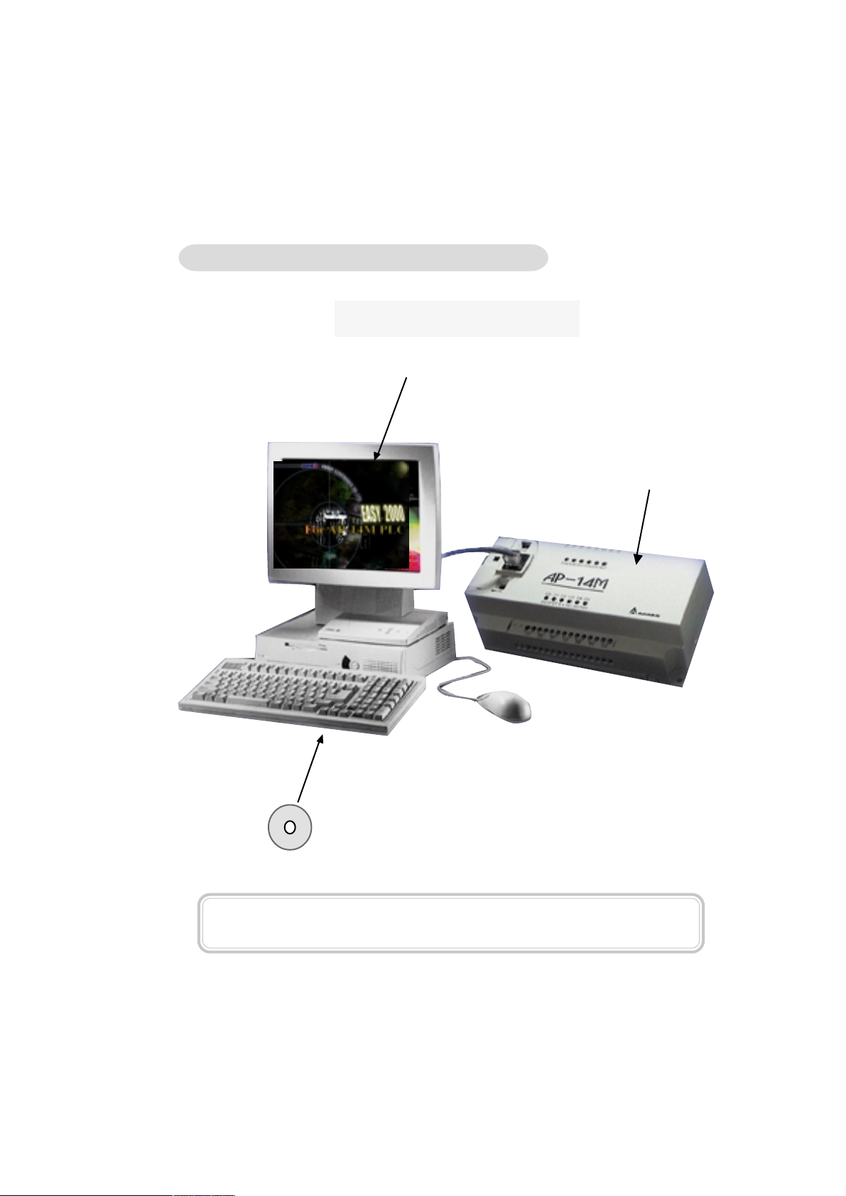
1.3.1 EASY2000 Programming Software
Program AP-14 on PC
Personal Computer
EASY-2000
AP-14M PLC
EASY-2000 Software (Please refer to PART TWO)
When EASY2000 is in available, you can program, communicate with AP-14M
PLC, read/write programs, simulate or step PLC on Personal Computer.
1-3
Page 6
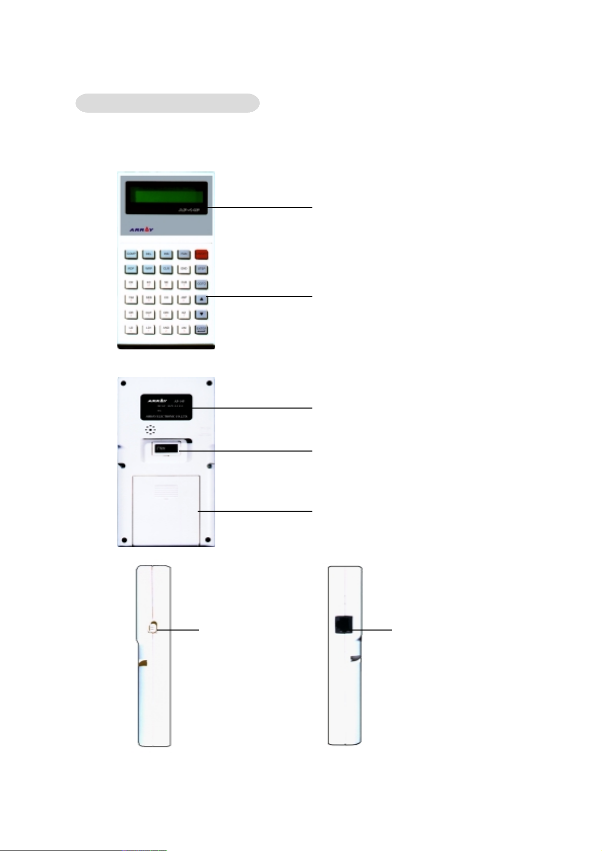
1.3.2 Ap-14P Programmer
Combing portable AP-14P programmer and AP-14M PLC is available to programming edit,
step test, and debug.
Liquid Crystal Display (LCD)
Button
Power Knob
Up(POWER): Power off
Down(BATTERY): Power on
Specification Brand
Special contact for EEPROM writer
(memory is available to replace to
keep changeable programs)
Battery Cover (AA
¡°¡°
¡°4pcs inside)
¡°¡°
Programmer cable contact
1-4
Page 7

Chapter 2 Specification
2.1 General Specification
Item
Voltage
Power
Cooling method
Operating temperature
Ambient humidity
Storage temperature
Operating environment
Vibration-proof
Shock-proof
Sensor power supply
Specification
AC 110V/220V(50/60Hz single-phase)
12W
Air cooling
- 5¢XC ~ +55 ¢ X C
45~85%RH (non-condensing)
- 25¢XC ~ +75 ¢X C
no dust, no conductive powder, no corrosive
gases, no oil fogs or no too much salt
16.7Hz, X, Y, Z direction 30min
15G, X, Y, Z direction 3times
DC24V( +15%), max 50mA
Momentary interrupt
of the power
Programmer
Control panel indicator
Installation method
Program writing
Age of program storage
Electrostatic Discharge 6KV contact discharge ( super class)
Pulse 2KV power wire
Insulation Resistance
Interrupt time
< 0.5a.c. cycle, interval ¡Ù 1s
Handheld programmer, PC programming software(EASY2000)
ERR: red; others: Green
direct installation (fixed with the screwdriver) or fixed with DIN rail
10,000,000 times
200 years
100M
£[£[
£[
£[£[
2-1
Page 8

2.2 Function Specification
Item Specification
Operating version Program storage
Control method Cyclic scan
Programming language
Program memory EEPROM
Program memory
240 steps
Special language for the controller(Ladder logic, Instruction list)
capacity
Instruction list
Input relay (I) 8 points I0~I7
Output relay (O) 6 points O0~O5
Internal relay (M) 32 points M00~M31
Timer (T) 4 points T0~T3 the presetting time range:[0.01~255s]
Counter(C) 4 point C0~C3 the presetting count range:[001~255T]
Self diagnostic module
15 instructions(including Basic logic, timer and counter instruction etc)
program checking (Grammar, Circuit); WATCH DOG monitor
2-2
Page 9
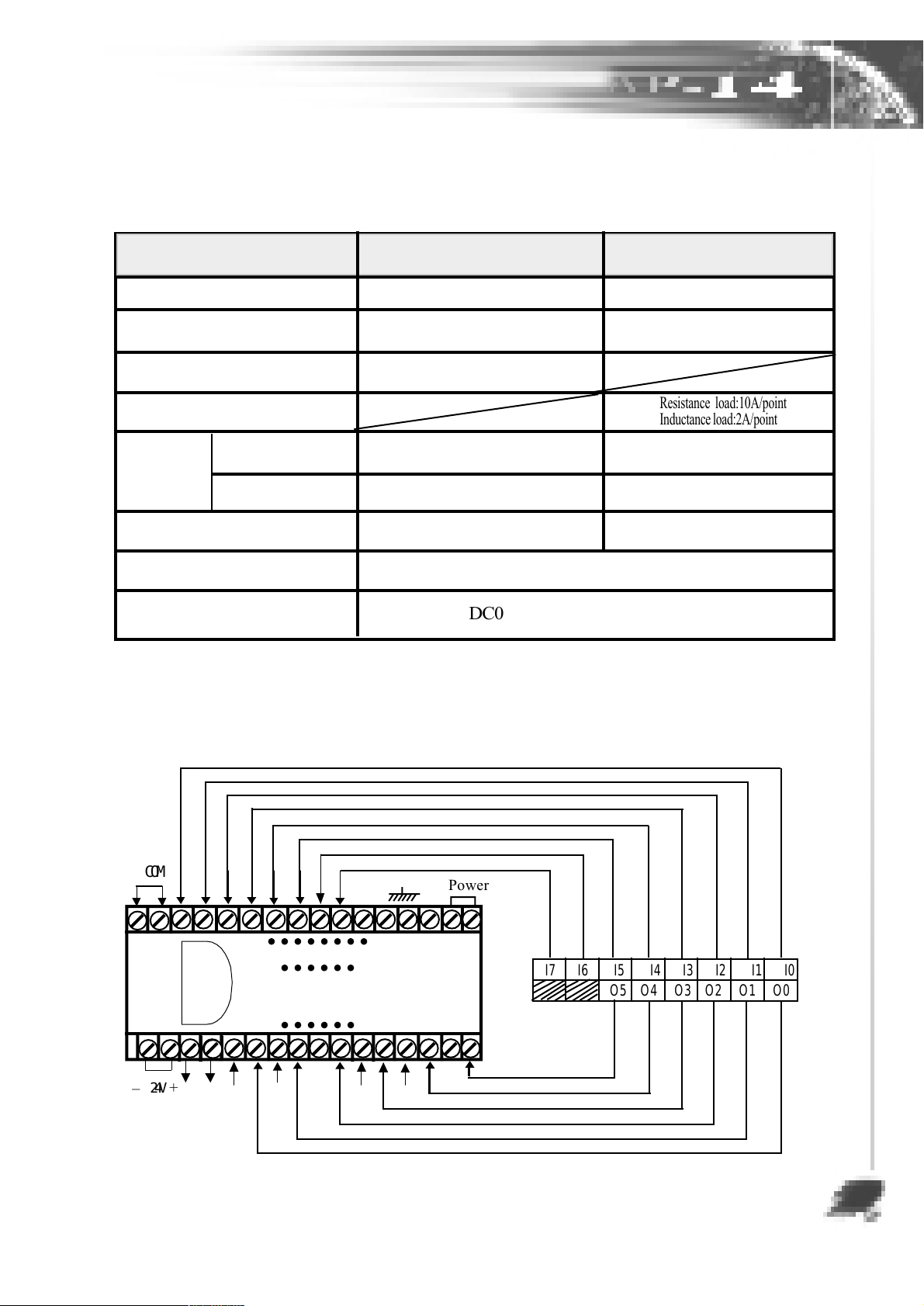
2.3 Input/Output Specification
12
12
12
12
12
12
Item Input part Output part
I/O version photo coupler relay output
I/O defined code I0~I7 O0~O5
Input voltage DC24V
Single-point current
ON/OFF 8mS 8mS
Response
OFF/ON 8mS 8mS
time
I/O signal indication
LED flashes green when
input is active
DC10V~30V(typical value: 24V)
High level voltage range
in input port
(1)
Low level voltage range
in input port
(0)
DC0V~3V(typical value: 24V)
Resistance load:10A/point
Inductance load:2A/point
LED flashes green when
output is active
2.4 Terminal Setting and Address Distributing
COM
_
24V
Power
I7 I6 I5 I4 I3 I2 I1 I0
AP-14M
O5 O4 O3 O2 O1 O0
+
2-3
Page 10

2.5 Name and Function of Sub-parts
(10)
(1)
(2)
(3)
(4)
(1) Input terminal row
Receive/refuse power and signal of input
(2) Program button
Press it when write the programs
(3) Program circuit contact
Combining programmer circuit is available
to write programs
(4) Installation port
Available to install and fix screw
(5) Keeping memory knob
Choose MEMORY modules
(6) Normal/single-operation switch
Choose normal/single operation
(combining with programmer/
EASY2000)
(7) Output terminal row
Receive/refuse the output signal
(9)
(8)
(7)
(6)
(5)
(9) Status display LED
POW(green): light on: normal power
RUN(green): light on: normal operate
PRO(green): light on: write/read programs
S I N (green): light on: single operate
ERR(red): light on: wrong operate
MEM(green): light on: choose
MEMORY modules
(10) Input display LED(green)
Display input status, lights on when input
is active
(11) Voltage knob
Choose 110V/220V
(12) DIN rail installation part
Install the rail which supportsDIN
(13) Slide module
tighten/loose DIN rail
(11)
2-4
(8) Output display LED(green)
display output status, LED lights on
(12)
when output is active
(13)
PROGRAMMABLE
ARRAY ELECTRONIC
Page 11
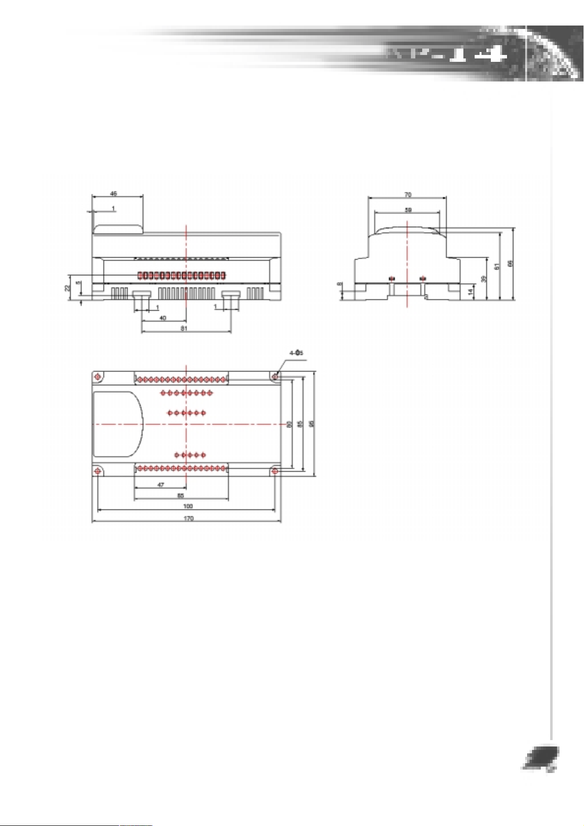
2.6 Dimension and Setting Drawings
[MEASURE: mm]
2-5
Page 12

Chapter 3 Structure and Description
of AP-14 Hardware
3.1 The Devices Overview
The designated capacity and the initial value are available for application as the following:
Device
symbol
I
O
M
T
C
Input relay
Output relay
Counter
Name
Internal
relay
Timer
Memory
address range
I0-I7
O0-O5
M00-M31
T0-T3
C0-C3
Capacity
8
points
6
points
32
points
4
points
4
points
Initial
value
the output data
OFF(keep the previous state with keeping module if power
failure)
Ditto
Ditto
Ditto
Function
Receive the input
D.C signal
Operate out-load
Control the midway
status of I/O contact,
timer, counter
timer
counter
3-1
Page 13
3.2 Description of Various Devices
3.2.1 Input/Output (I/O) Relay
I stands for input relay, Symbol: 10-17, totaling 8, separately connecting positive
power of inputting signal. COM is the public contact for I0-I7 negative terminals,
connecting negative D.C.
O stands for output relay, Symbol: O0-O5, totaling 6.
Bus of programmable logic Controller is available to receive input signal of switch
and send output signal to load.
The normal open contact and normal close contact of I/O relay can be used without
limit.
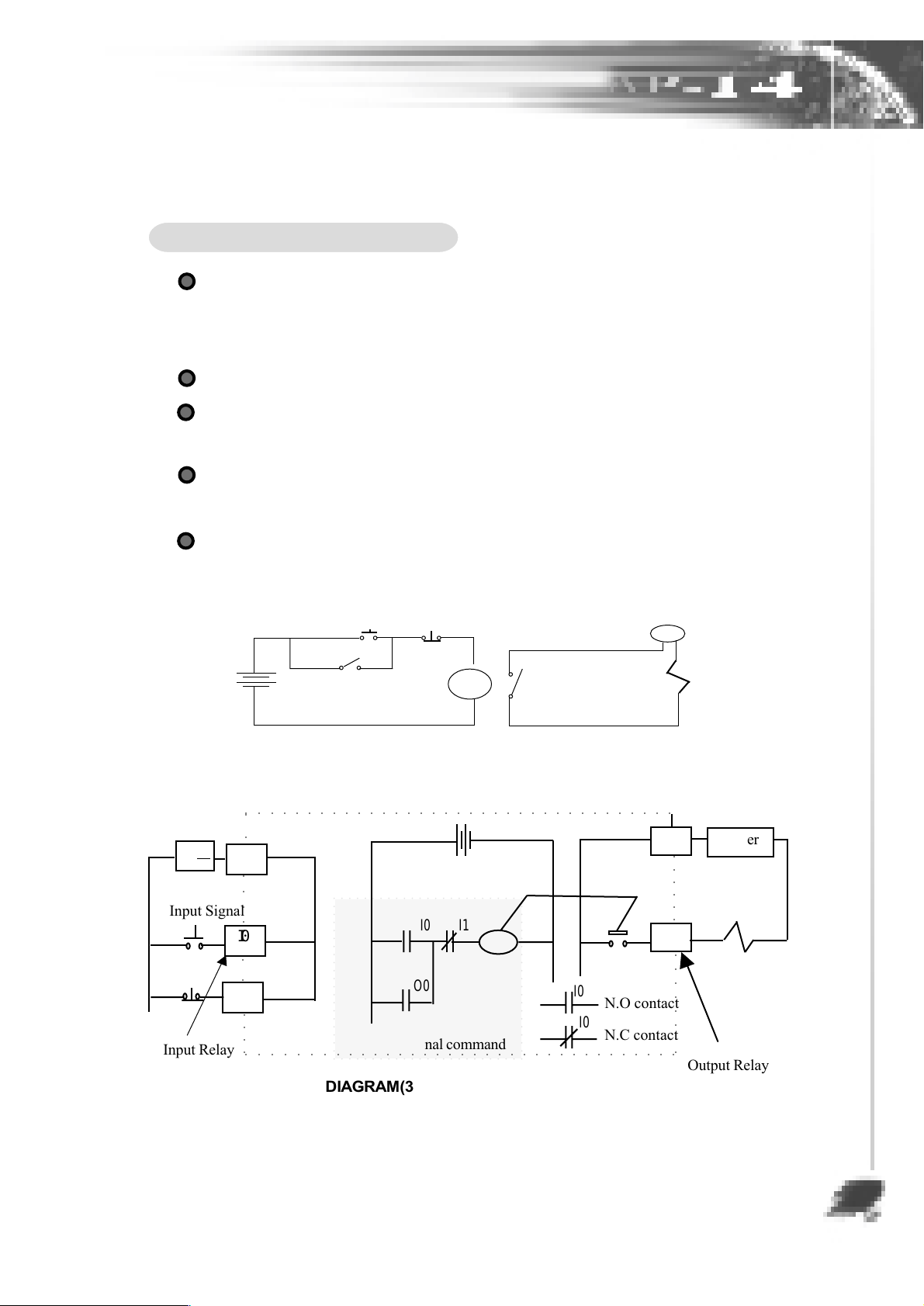
Function of I/O relay is as the following diagram (3-1):
DC24V
¡Ï
Input Signal
Input Relay
Start
N.O.contact 1
Stop
coil
Power
N.O contact 2
DIAGRAM(3-1)a: Self-keeping Circuit
○○ ○○○○○○○○○○○○○○○○○○○○○○○○○○○○○○○○○
○○
COM
○○○○
O0
I0
○○
I1
○○○○
I0 I1
O0
OUT
I0
N.O contact
I0
○○○○○○○○○○○○○○○○○○○○○○○○○○○○○○○○○○○
PLC internal command
N.C contact
DIAGRAM(3-1)b:Self-keeping by PLC I/O Relay
AC
~
Load
O0
○○○○○○
O0
○○○○○○○○
Output Relay
Power
load
3-2
Page 14
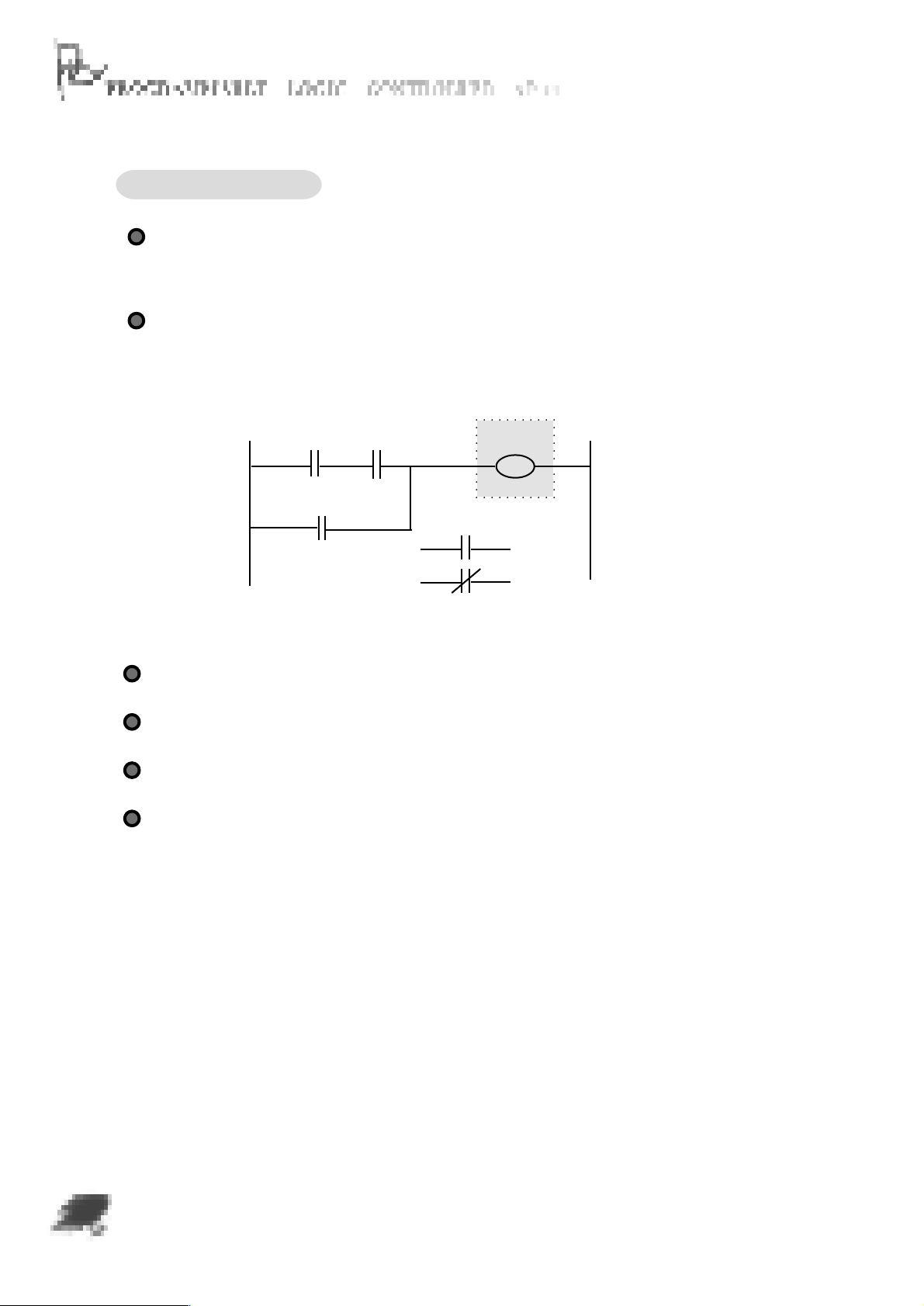
3.2.2 Internal Relay
M stands for internal relay, total 32 internal relays (M00-M31) are available. The N.O.
contact of internal relay is off while the N.C.contact on when machine is powered. Please
see diagram (3-2)
Internal relay contact is unable to output directly
Please see diagram (3-2):
I0 I1
I2
DIAGRAM(3-2)
M00
OUT
M00
N.O CONTACT
M00
N.C CONTACT
If want to change contact state, operate OUT, SE, CR, SEB, CLB etc commands.
Any of PLC contact can operate internal relay, whose coil operates same as output relay.
Internal relay is available to keep intermediate state as the internal contact.
The N.O. contact and N. C. contact of the internal relay can be used without limit.
3-3
Page 15
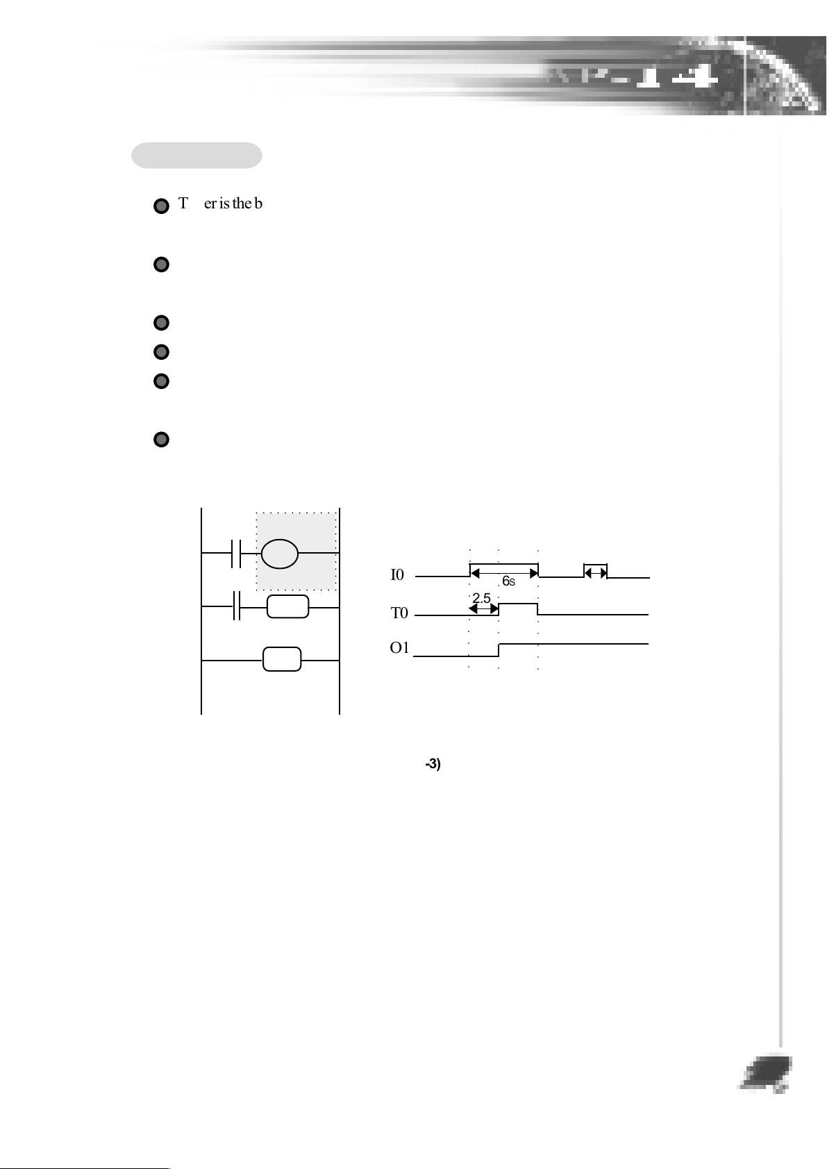
3.2.3 Timer
Timer is the built-in time limit internal relay of the PLC. When it reaches the
presetting data, the output contact operates.
T stands for timer, 4 timers(T0-T3) are available and each with the time range
of [0.01~255]seconds.
Series-timers can time 4,228,250,625 seconds(1,174,514 hours).
The N.O/N.C contact of timer can be used without limit.
With memory module, PLC can keep timing status in event of power failure.
(Refer to chapter 2.5 for more information about memory module)
Timer operating diagram is as the following:
T0
I0
T0
T
O1
SE
KZ002
KC050
I0
T0
○○○○○○○○○○○
○○○○○○○○○○○
65
2.55
25
END
O1
○○○○○○○○○○○
DIAGRAM(3-3)
3-4
Page 16
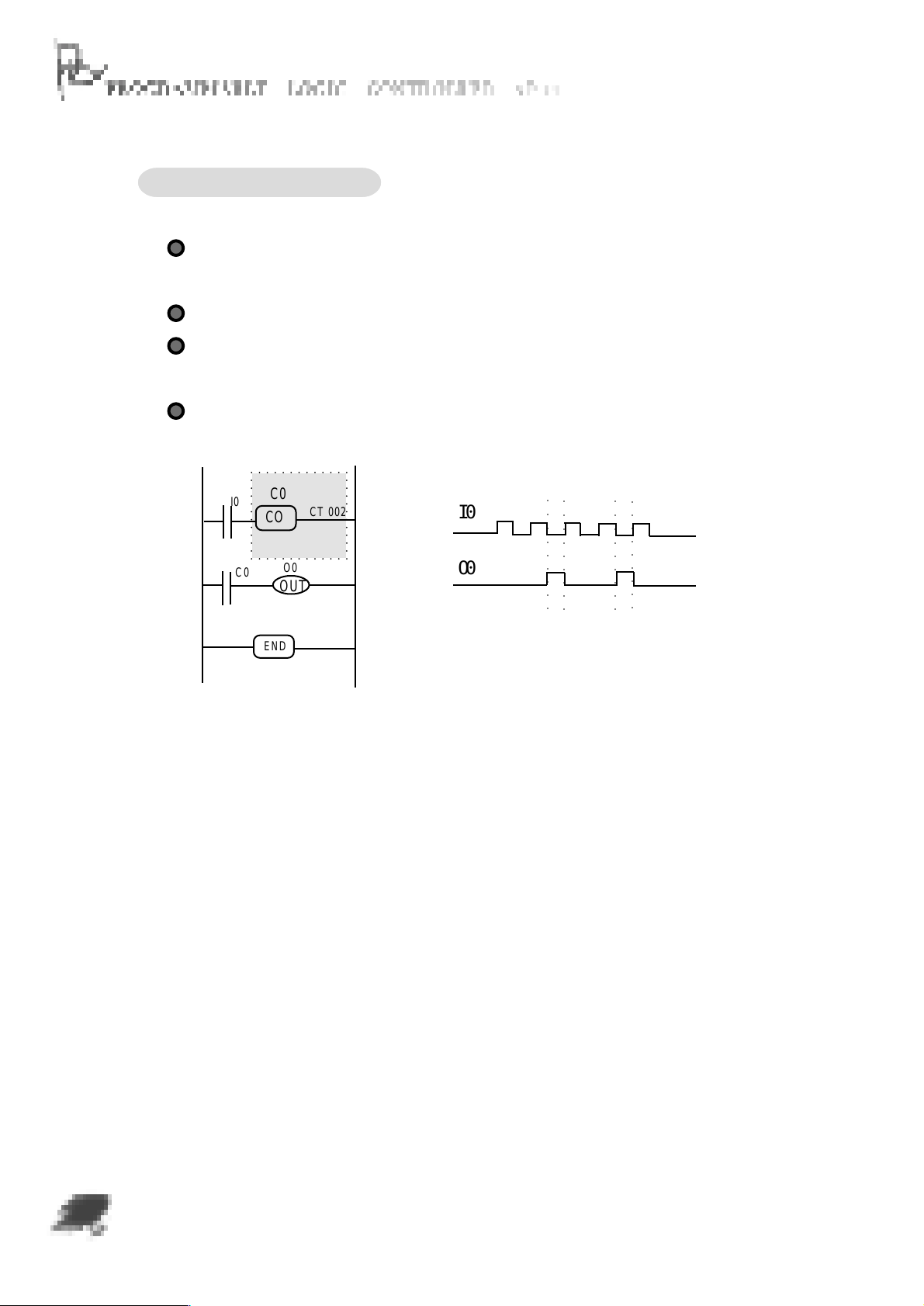
3.2.4 Cycling Counter
C stands for cycling counter, 4 counter (C0-C3)are equipped in PLC and each with
a count range of [001~255]T.
Series-counters can count 4,228,250,625 times.
With memory module, PLC can automatically keep counting status in the event of
power failure. (Refer to chapter 2.5 for more information about memory module)
Cycling Counter operating diagram is as the following:
C0
I0
C0
CO
O0
CT 002
I0
O0
○○ ○○○○○○○
○○ ○○○○○○○
○○ ○○○○○○○
○○○○○○○○○
OUT
END
DIAGRAM(3-4)
3-5
Page 17
Chapter 4 Instruction
4.1 Instruction Overview
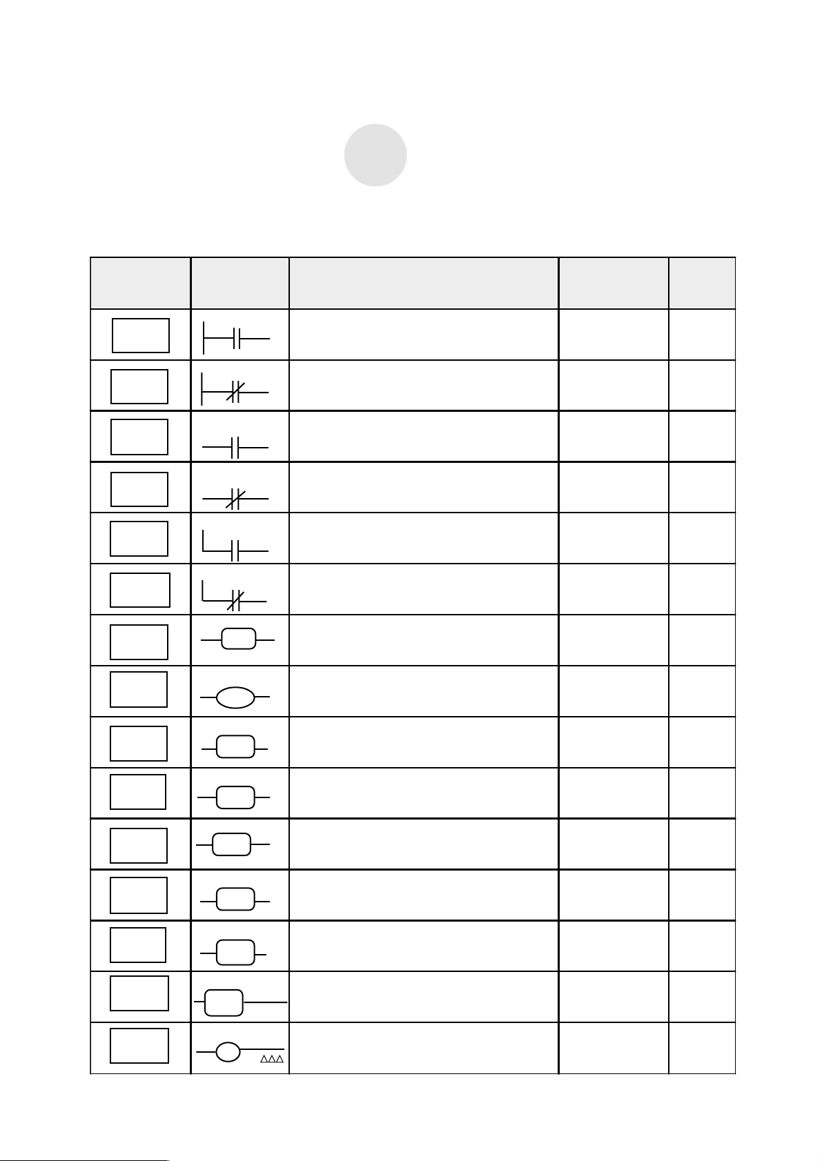
The following diagram shows the instructions of the AP-14 system, totaling 15.
command
symbol
LD
LDI
AND
ANI
OR
ORI
END
X
X
X
X
X
X
END
functionsymbol
combine N.O. contact with the bus
combine N.C. contact with the bus
series-connect an N.O. contact
series-connect an N.C. contact
parallel-connect an N.O. contact
parallel-connect an N.C. contact
program ends
parameter
I, M, O, T, C
I, M, O, T, C
I, M, O, T, C
I, M, O, T, C
I, M, O, T, C
I, M, O, T, C
no operation
parameter
pages
4-2
4-2
4-3
4-3
4-4
4-4
4-3
OUT
SE
SEB
CR
CLB
JMP
CO
TIM
X
OUT
X
SE
X
SEB
X
CR
X
CLB
XXX
JMP
X
CO
X
T
CTXXX
KZXXX
KC
output the operating result
output relay or internal relay setting
internal relay setting
output relay or internal relay resetting
internal relay resetting
program toggle command
Cycling counter C
Timer
M
XXX
O, M
O, M
M
O, M
T
4-3
4-5
4-6
4-7
4-8
4-9
4-10
4-11
4-1
Page 18
4.2 Description of the Instructions
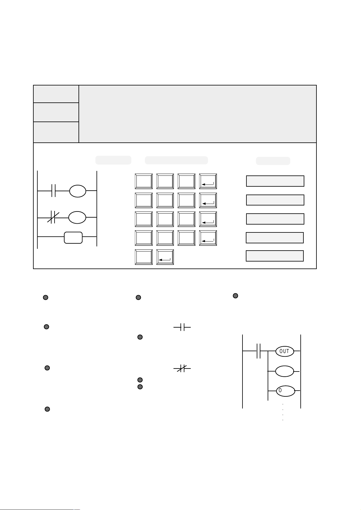
4.2.1 LD, LDI, OUT
LD
LD
LDI
OUT
combine N.O. contact with bus
LDI
combine N.C. contact with bus
OUT
output operating results
ADDRESS KEY OPERATION
O0
I0
OUT
000
001
O1
I1
OUT
END
002
003
004
DESCRIPTION
LD, LDI commands are available
to combine N.O and N.C contact
with bus.
The operating parameter of LD,
LDI commands are available for:
input relay ¡Boutput relay ¡B
internal relay¡Btimer ¡Bcounter.
OUT command is available to
output the operating result to
the internal relay and output
relay.
The operating parameter of OUT
command is only available for
the internal relay and output
relay.
LD CR LD
0 I 0
OUT SE LD
5 O 0
LDI CR LDI
1 I 1
OUT SE LDI
5 O 1
END
ENTER
ENTER
ENTER
ENTER
ENTER
TECHNICAL ITEMS
N.O. contact: the contact which is
open in static state, in ladder logic
diagram it shows as the following:
N.C. contact: the contact which is
closed in static state, in ladder logic
diagram it shows as the following:
O: the simplest form of OUTPUT
I: the simplest form of INPUT
LCD
000 LD I0
001 OUT O0
002 LDI I1
003 OUT O1
004 END
ATTENTION
Do not use the OUT command
continuously to form a circuit
as the following diagram:
I0
O0
OUT
O1
OUT
O2
OUT
○○○○
4-2
Page 19
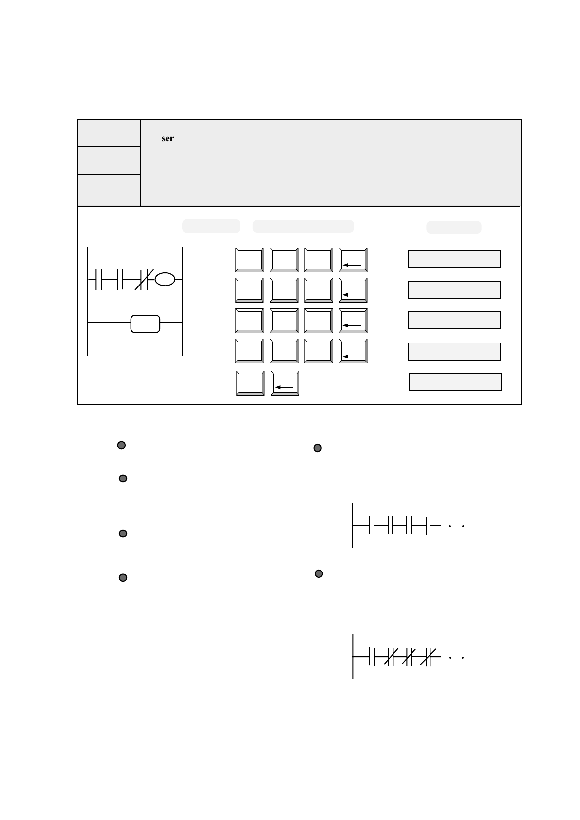
4.2.2 AND, ANI, END
AND
ANI
END
AND
series-connect an N.O. contact
ANI
series-connect an N.C. contact
END
program ends
ADDRESS KEY OPERATION
I2I0 I1
END
O0
OUT
000
001
002
003
LD CR LD
0 I 0
AND CR LDI
2 I 1
ANI CR AND
3 I 2
OUT SE LD
5 O 0
END004
ENTER
ENTER
ENTER
ENTER
ENTER
LCD
000 L D I0
001 AND I1
002 ANI I2
003 OUT O0
004 END
DESCRIPTION
AND: series-connect an N.O. contact
ANI: series-connect an N.C.contact
The operating parameter of AND ¡BANI
command is available for any of these:
input relay ¡Boutput relay¡Binternal
relay ¡Btimer ¡Bcounter.
END command is for the end of a program.
A program is unable to be executed without
it.
Enter END command at the end of each
section before the program operates, thus
it offers easy adjudgment of the opera-
tion, delete the command after the program
confirms.
SUPPLEMENT
AND command is available for continuous
series-connection as needs, the diagram is
as the following:
I0 I3I2I1
○○
ANI command is available for continuous
series-connection as needs, the diagram is
as the following:
I0 I3I2I1
○○
4-3
Page 20
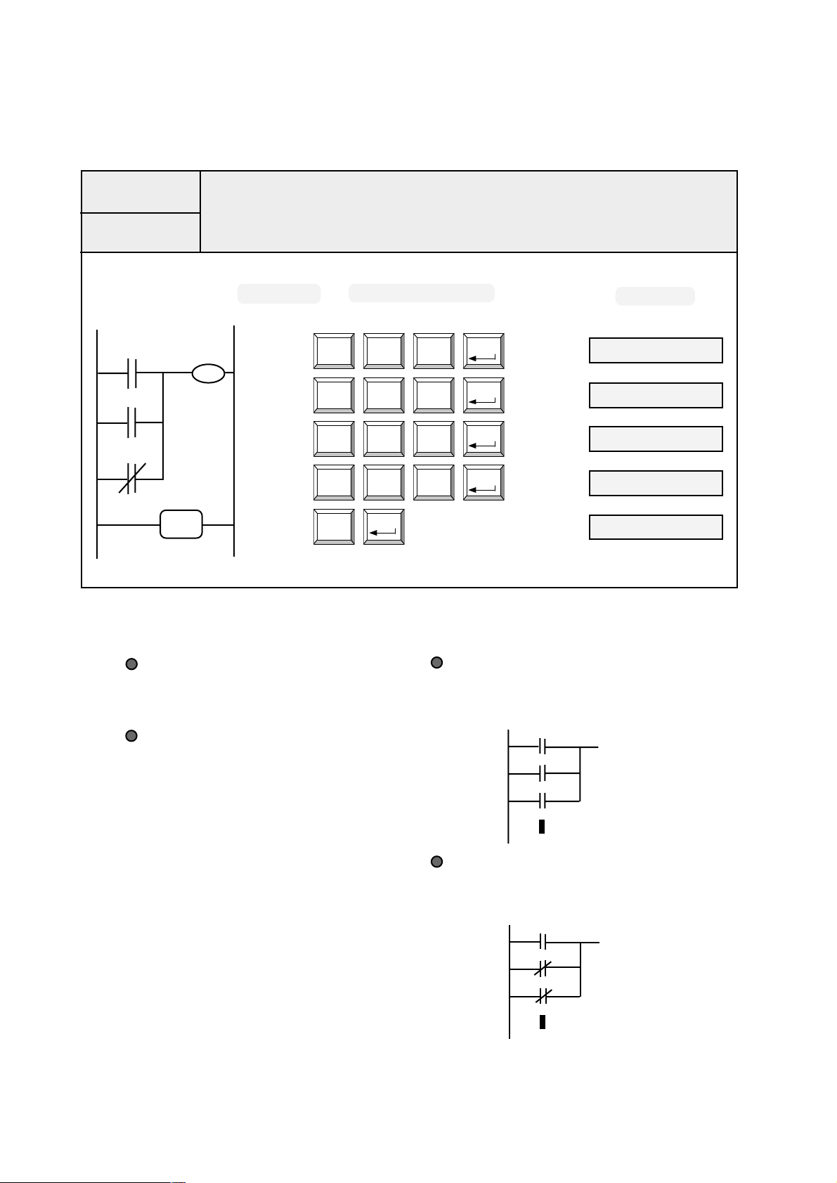
4.2.3 OR, ORI
OR
ORI
I0
I1
I2
O0
OUT
END
OR
parallel-connect an N.O. contact
ORI
parallel-connect an N.C. contact
ADDRESS KEY OPERATION
LD CR LD
0 I 0
001
002 002 ORI I2
003
OR CR LDI
4 I 1
ORI CR AND
6 I 2
OUT SE LD
5 O 0
END004
ENTER
ENTER
ENTER
ENTER
ENTER
000 LD I0000
001 OR I1
003 OUT O0
004 END
LCD
DESCRIPTION
OR: parallel-connect an N.O. contact
ORI: parallel-connect an N.C. contact
The operating parameter of OR¡BORI
command is available for any of these:
input relay¡Boutput relay ¡B internal
relay¡B timer counter
SUPPLEMENT
OR command is available for continuous
parallel-connection as needs, the diagram
is as the following:
I0
I1
I2
ORI command is available for continuous
parallel-connection as needs, the diagram
is as the following:
I0
I1
I2
4-4
Page 21
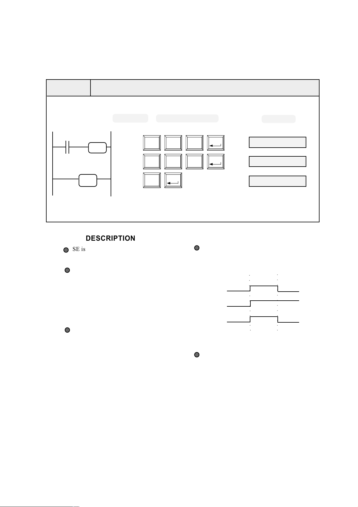
4.2.4 SE
S E
Internal relay and output relay setting command
ADDRESS KEY OPERATION
I0
END
O0
SE
000
001
002
DESCRIPTION
SE is the setting command for
internal relay and output relay.
SE command is available for de-
ciding whether to execute this
command or not by referring to
the previous operating results,
execute it when the result is 1, do
not execute it when the result is 0.
The operating parameter of SE
command is available for internal
relay or output relay.
LD CR LD
0 I 0
SE SE LD
O O 0
END
ENTER
(OPERATE SE)
(OPERATE OUT) O0
LCD
ENTER
ENTER
000 LD I0
001 SE O0
002 END
SUPPLEMENT
The diagram result will be as following when
replacing SE command by out command.
○○○○○○○○○○○○
○○○○○○○○○○○○
I0
O0
The above diagram shows:
when I0 changes from 1 to 0, execute SE
command and the result remains 1 while
it changes from 1 to 0 by executing OUT
command. That is the difference
between SE and OUT command.
4-5
Page 22

4.2.5 SEB
SEB
internal relay setting command
ADDRESS KEY OPERATION
I0
END
M00
SEB
000
001
002
LD CR LD
0 I 0
SE KC LD LD
O M 0 0
END
ENTER
DESCRIPTION
SEB is the setting command for internal relay.
SEB command has the same function as SE, but the operating
parameter of SEB command is only available for internal relay while
SE for either internal relay or output relay.
ENTER
ENTER
LCD
000 LD I0
001 SE M00
002 END
4-6
Operate the above-mentioned commands, the sequence
diagram is as the following:
○○○○○○○○
I0
M00
Page 23

4.2.6 CR
CR
internal relay and output relay reset command
ADDRESS KEY OPERATION
I0
O0
000
SE
I1
O0
001
CR
002
LD CR LD
0 I 0
SE SE LD
O O 0
LD CR LDI
0 I 1
END
003
004
CR SE LD
I O 0
END
ENTER
DESCRIPTION
CR is the reset command for internal relay and
output relay.
CR command is available for deciding whether
to execute this command or not by referring
to the previous operating results, execute it
when the result is 1, do not execute it when
the result is O.
CR command is available for the internal relay
or the output relay.
Operate the above-mentioned commands, the
sequence diagram is as the following:
LCD
ENTER
ENTER
ENTER
ENTER
000 LD I0
001 SE O0
002 LD I1
003 CR O0
004 END
SUPPLEMENT
Change the above-mentioned diagram as the
following:
I0
I1
The sequence diagram is as the following:
I0
O0
CR
O0
SE
END
○○○○○○○○○○○
○○○○○○○○○○○
I0
I1
O0
○○○○○○○○○○○○
○○○○○○○○○○○○
○○○○○○○○○○○○
I1
O0
When SE and CR are both available for
operating number O0, operate the latter
one.The rule is: the latter suppresses the
former.
4-7
Page 24

4.2.7 CLB
CLB
I0
I1
END
M00
SEB
M00
CLB
internal relay reset
ADDRESS KEY OPERATION
LD CR LD
0 I 0
001
002 002 LD I1
003
SEB KC LD LD
9 M 0 0
LD CR LDI
0 I 1
CLB KC LD LD
T M 0 0
END004
ENTER
ENTER
ENTER
ENTER
ENTER
000 L D I0000
001 SEB M00
003 CLB M00
004 END
LCD
DESCRIPTION
CLB is the reset command for internal relay.
CLB command has the same function as
CR, but the CLB operating parameter is
only available for internal relay while CR
for either internal relay or output relay.
Operate the above-mentioned commands,
the sequence diagram is as the following:
○○○○○○○○○○○○
○○○○○○○○○○○○
○○○○○○○○○○○○
I0
I1
M00
SUPPLEMENT
Change the above-mentioned diagram as the
following:
I0
M00
CLB
I1
M00
SEB
END
Operate the above-mentioned commands, the
sequence diagram is as the following:
○○○○○○○○○○
I0
○○○○○○○○○○
I1
M00
4-8
Page 25

4.2.8 JMP
JMP
I1
I2
I1
003
JMP
END
XXX
JMP
JMP command is available for transferring to the following
relative XXX steps
ADDRESS KEY OPERATION
LD CR LDI
0 I 1
JMP LD LD ANI
C 0 0 3
LD CR AND
0 I 2
OUT SE LDI
5 O 1
LD CR LDI
0 I 1
OUT SE AND
5 O 2
END
ENTER
O1
OUT
O2
OUT
000
001
002
003
004
005
006
ENTER
ENTER
ENTER
ENTER
ENTER
ENTER
*
*
006 END
LCD
000 LD I1
001 JMP 003
002 LD I2
003 OUT O1
004 LD I1
005 OUT O2
DESCRIPTION
JMP command is available for transferring to the
following relative XXX steps.
JMP command is available for deciding whether
to execute this command or not by referring to the
previous operating result, execute it when the
result is 1, do not execute it when the result is
0.
See the example: when I1 is 1 ( condition of
executing JMP is satisfied to demmand), the
two commands with * fail to be operated.
The range of XXX in JMP command is [000~239],
it must be written as three figures, plus 0 to be
three if it is less than three, e.g. 001 for 1,
011 for 11.
SUPPLEMENT
The sequence diagram is as the following:
○○○○○○○○○○○○○○
○○ ○○○○○○○○○○○
○○○○○○○○○○○○○○
I1
I2
O1
O2
4-9
Page 26

4.2.9 CO
CO
I0
C0
CO
END
C0
OUT
O0
CT 002
X
CO
CT XXX
CO command is available for the cycling counter
ADDRESS KEY OPERATION
000
001
002
003
004
005
LD CR LD
0 I 0
CO JMP LD
C 0
LD LD AND
0 0 2
LD JMP LD
0 C 0
OUT SE LD
5 O 0
END
ENTER
ENTER
ENTER
ENTER
ENTER
ENTER
LCD
000 LD I0
001 CO C0
002 CT 002
003 LD C0
004 OUT O0
005 END
DESCRIPTION
CO command is available for the cycling counter,
including two sub word commands: CO X and CT
XXX. X stands for the cycling counter in this comm-
and including such as C0, C1, C2, C3 in a total of 4pcs.
XXX stands for presetting value of counter.
CO command is available for deciding whether to
execute this command or not by referring to the previous
operating result. When the result changes from 1 to 0,
execute it till it reaches the presetting value and the
counter sets 1.
When the data reaches the presetting one, the counter
is 1, if still any active pulse on the former command
and the following pulse comes, counter resets 0 and
counts again. This action cycles on.
The range of XXX in CO command is [000,255],
it must be written as three figures, plus 0 to be
three if it is less than three, e.g. 1 for 001,
11 for 011.
SUPPLEMENT
Operate the above-mentioned commands, the
sequence diagram is as the following:
○○ ○○○○○○○
○○ ○○○○○○○
○○○○○○○○○
○○ ○○○○○○○
I0
C0
O0
While program with programmer, if input CO
and press Enter button, the programmer will
show CT automatically. No need to input CT
CO JMP LD
C 0
The diagram of the programmer LCD is as the
following:
001 CO C0
002 CT
ENTER
4-10
Page 27

4.2.10 TIM
TIM
X
T
KZ XXX
KC¡µ¡µ¡µ
timer
ADDRESS KEY OPERATION LCD
LD CR LD
0 I 0
TIM CLB LD
8 T 0
KZ LD LD AND
7 0 0 2
KC LD OUT LD
M 0 5 0
LD CLB LD
0 T 0
I0
T0
T
T0
O1
SE
KZ002
KC050
000
001
002
003
004
END
005
006
SE SE LDI
O O 1
END
ENTER
DESCRIPTION
TIM command is available for the timer.
TIM command is available for deciding whether to
execute this command or not by referring to the
previous operating result. When the result is 1,
execute it till it gets to the presetting value. When
the result is 0, the timer doesnt work.
When time reaches presetting value, timer sets 1,
if not , the result changes from 1 to 0, and timing
will not be stored, when result comes to 1, timer
runs on again.
The predetermined integer part of XXX ranges
from 000 to 255, it must be written as three figures, plus
0 to be three if it is less than three, e.g. 1 for
001, 11 for 011. The predetermined decimal part
¡µ¡µ¡µ¡µ¡µ¡µ
of
¡µ¡µ¡µ ranges from 000 to 099, it also must be
¡µ¡µ¡µ¡µ¡µ¡µ
written as three figures, too. For example: 10.99S
for KZ010, KC099 .
ENTER
ENTER
ENTER
ENTER
ENTER
ENTER
000 LD I0
001 TIM T0
002 KZ 002
003 KC 050
004 LD T0
005 SE O1
006 END
X stands for the cycling counter in a total
of 4pcs as T0, T1, T2, T3 with the range
{0.01-255} S. Accuracy is 0.01S.
TIM includes three essential sub-commands:
TIM, KZ, KC. Everyone is necessary.
The sequence diagram is as the following:
○○○○○○○○○○○
○○○○○○○○○○○
I0
6S
2S
2 .5 S
T0
O1
○○○○○○○○○○○
4-11
Page 28

Chapter 5 Programmer
5.1 Description of the Programmer
operation button
function button
power switch
the upper part is the com-
mand botton, the lower
one is the digital and letter
button
DESCRIPTION
Function button
Ć
The following two Function modes can be
designated:
(1) Select ON/OFF of the sound.
(2) Select whether to charge the battery or not
Operation buttons:
compare the programs in the programmer
COMP
EEPROM with those in the PLC EEPROM.
delete the comands and addresses
DEL
insert a line of command in front of the
INS
current address
read the program from the PLC EEPROM
RDP
write the programs in the PLC EEPROM
WRP
clear the contents at the current cursor
CLR
address except line number.
toggle to the designated address.
GOTO
STEP
test by single-step
FUN
operation button
confirming button
display the contents at the previous cursor address
display the contents at the following cursor
address
confirming button
ENTER
when finish one line command, press this button to comfirm. But be careful to press it to
avoid the unnecessary correction under other
situations
ON/OFF power switch
ON/OFF
When the battery supplies the programmer,
push the button down for 3 seconds for power
on. Push the button down again for 3 seconds
for power off .
Instruction Button
The upper part of the button is the command
button for inputting commands: LD/LDI/OR/
ORI/AND/ANI/TIM/CO/SE/SEB/CR/CLB/JMP/
OUT/END/KZ/KC, totaling 17. (refer to Chapter
4: Instruction for details)
digital button and letter button
The lower part consists of the ten digital keys:
1~9 and five letter keys: I, M, O, T, C. Available
for setting address, input relay, output relay,
internal relay,and data of timer and counter
5-1
Page 29

5.2 The Operating Procedure of the Programmer
(a) Adjust the programmer power switch to
BATTERY.
(b) Combine with the programmer cable
(c) Press ON/OFF button for 3 seconds, the
start
LCD displays as the following:
ARRAY electronic
co., ltd
input
programs
check
programs
write
programs
The above mentioned LCD view lasts for 3s,
then the system is in status of inputting program.
(a) the contents at 000 line will be shown if
the program exists in progammer, see following
figure:
000 LD I0
001 OR I1
now you can check the former programs
by pressing and
or press to correct it,
After the program is inputted, press or button to check
whether the inputted program is identical to the original one.
Press the WRP button, write the program to the PLC EEPROM, the LCD
displays as the following:
CLR
Writing
○○
or edit the new program;
(b) it will automatically be in editing
status if no program, see following
figure:
000
001
now you can start new program.
Cut off Power supply
end
Press button for 3s to cut power supply.
ON/OFF
DESCRIPTION
In the process of editing programs, the poor light of
the LCD will be turned off when no keys are pressed
within 20 seconds, press any of the button, the light
turns on. LCD will be turned off if no keys are pressed
after 5 minutes. The power of the programmer will be
cut off and in rest status when no keys are pressed within
10 minutes, as continue editing it must be started again.
Description of the LCD displaying.
(1) graphic marks
Stands for inputting command.
5-2
Write OK!
Stands for result of inputting commands.
Available for digital keys and letter keys.
(2) For error displays
RomERROR: ROM error or wrong symbol
for command.
RamERROR: RAM error
CodeERROR: Code error in RAM
Eeprom ERROR: no menory or some wrong
with program memory
OperationERROR: operation data exceeds the
range (¡Ù256) while running INS/DEL/GOTO;
or other wrong operation, it will display with
an alarm .
Page 30

5.3 Description of the Function Button
FUN
Function Button
Function LCD Operating method
Press the
FUN button
at the first
FUN
Voice knob
time
Press the
FUN button
at the
FUN
battery charge knob
second time
DESCRIPTION
Press the FUN button, the system will return to the
editing state automatically after 5 seconds when no
selection is made.
To decide if the battery needs charge or not, the system
will check the battery voltage automatically. Please
pay attention to the system recommadation
(1) As battery voltage<4.2V, the LCD displays alarm
smybol: # on right bottom as the following:
Speaker (1 OR 0)
1=ON 0=OFF
Charge(1 OR 0)
1=YES 0=NO
select to charge, the LCD displays
as the following:
After charging, the LCD displays
as the following:
Press to turn on the
1
0
1
0
LDI
LD
LDI
LD
sound switch
Press to turn off the
sound switch
Press to charge
the battery
Press not to charge
the battery
Charging
Charge OK!
003 JMP 008
#
(2) As battery voltage<3.8V, the system will switch off
the poower automatically. Now the user should connect
the charger to A.C. supply, plug the charger cable to
programmer and start the programmer, press the button
twice,the programmer is turned into the state of
FUN
selecting charging and then press the button ,
1
LDI
The user may take the charger away and edit.
(3)When the energy of the battery is ran out,
please connect the charger to A.C. supply, plug
the charger cable to programmer to charge the
battery. After 10 hours, take the charger away,
the programmer is ready for programming.
5-3
Page 31

5.4 Description of the Operation Button
5.4.1 Description of the Operation ButtonINS
INS
Insert new command in the designated program address
Basic operating procedure (example)
I0I2I1
O0
OUT
INSERT
I3
END
If insert 003 AND I3 below 002, do as the following:
(1) Press
(2) Press
(3) Press
INS
LD
0
AND CR ANI
2 I 3
LD
0
ANI
3
LCD
000 LD I0
001 AND I1
002 OR I2
003 OUT O0
004 END
INS
INS 003
003
INS 003
003 AND I3
ENTER
(4) Press
the result is as the following:
I3
I1
I0
I2
O0
OUT
END
DESCRIPTION
Insert new command in the designated address, the following command
addresses will increase 1 automatically. If the inserted program exceeds
the maximum address range, the system will show error.
If press with no command being inserted, and press ,
a blank line will be inserted
If no command is inserted when press , can not use
INS
INS
000 LD I0
001 AND I1
002 OR I2
003 AND I3
004 OUT O0
004 END
ENTER
5-4
to exit current state.
Page 32

5.4.2 Description of the Operation ButtonDEL
DEL
delete the contents at the current cursor address including the line number
Basic operating procedure (example)
I1
I0
O0
OUT
I2
DELETE
END
If delete 001 AND I1, do as the following:
(1) press
(2) press
DEL
LD
0
LDI
LD
1
0
LCD
000 LD I0
001 AND I1
002 OR I2
003 OUT O0
004 END
DEL
DEL 001
(3) press
ENTER
Waiting for about 2s, the result will be as the following:
I0
O0
OUT
I2
END
DESCRIPTION
Delete the content at the designated address, thus the
following address decreases 1 automatically and the next
line moves forward.
When deleting some commands, be sure to delete the
relative commands, e.g. when deleting command CO, the
relative command CT should be deleted too.
000 LD I0
001 OR I2
002 OUT O0
003 END
5-5
Page 33

5.4.3 Description of the Operation Button CLR
CLR
clear the program contents instead of row number in order to input new program
Basic operating procedure (example)
I2
I0
I1
CLEAR
O0
OUT
O0
CHANGE TO
END
If change 001 OR I1 to 001 OR O0 , do as the following:
(1) at 001, press
(2) press
OR SE LD
4 O 0
CLR
LCD
000 LD I0
001 OR I1
002 AND I2
003 OUT O0
004 END
001
001 OR O0
(3) press the result will be as the following:
ENTER
(4) after the program is changed, press to browse
and check the changed contents
I0
O0
O0
I2
OUT
END
000 LD I0
001 OR O0
002 AND I2
003 OUT O0
004 END
5-6
Page 34

5.4.4 Description of the Operation Button GOTO
GOTO
search the address
Basic operating procedure (example):
LCD
000 LD I0
I0I2I1 I3
END
the programmer is displaying the 004 address, if read the content of the 002 address, do as the
following two methods:
(A) use , continuously until display the contents at the 002
O0
OUT
press
001 AND I1
002 OR I2
003 AND I3
004 OUT O0
005 END
(B) use
(1) press
(2) press
(3) press after 2 seconds displays the contents
GOTO
GOTO
LD
0
ENTER
LD
0
AND
2
at 002 line address
GO
GO 002
002 OR I2
5-7
Page 35

5.4.5 Description of the Operation Button COMP
compare the contents in the programmer EEPROM with the program in the PLC EEPROM
COMP
Basic operating procedure (example):
I0I2I1
O0
OUT
000 LD I0
001 AND I1
LCD
002 OR I2
003 OUT O0
END
004 END
If compare the program in programmer EEPROM with the written program in PLC EEPROM, do as the following:
(1) Combine programmer with PLC by specified cable,and set programmer
power switch for power supply
(2) press , LCD displays:
COMP
Comping
○○
(3) Compare with the contents in programmer EEPROM and the PLC EEPROM,
they are the same. LCD displays:
COMP OK !
(4) Compare with the contents in programmer EEPROM and the PLC EEPROM,
they are different; AP-14 and AP-14M PLC are in improper connection;
NORMAL/SINGLE or PROGRAM is improperly set.
LCD displays:
COMP ERROR !
5-8
DESCRIPTION
Notes: press PROGRAM switch on PLC before operating the
above mentioned button, and PRO indicator is on, then setNORMAL/
SINGLE switch to NORMAL.
The system will show error in such situations:
(1) The programmer cable doesnt connect to the designated socket.
(2) The programmer cable and the designated socket are in improper
connection.
(3) The program in the PLC EEPROM doesnt keep with that in the
programmer EEPROM.
Find out the reason first, then eliminate it in the event of system error.
Page 36

5.4.6 Description of the Operation Button WRP
WRP
write the programs in the programmer EEPROM to the PLC EEPROM
Basic operating procedure (example):
LCD
I1
I0
END
If write programs in the programmer EEPROM to the PLC EEPROM, do as the following:
(1) Combine programmer with PLC by specified cable,and set programmer
power switch for power supply
(2) Press
WRP
(3) Writing , LCD displays:
O0
OUT
000 LD I0
001 AND I1
002 OUT O0
003 END
Writing
○○
(4) Writing OK , LCD displays:
(5) AP-14 and AP-14M PLC line are in improper connection;
NORMAL/SINGLE or PROGRAM is improperly set.
LCD displays:
DESCRIPTION
When writing, eliminate the unnecessary program content in the PLC
EEPROM and at the same time write in new contents.
Notes: press PROGRAM switch on PLC before operating the above
mentioned button, and PRO indicator is on, then set NORMAL/
SINGLE switch to NORMAL.
Write OK !
Write ERROR!
5-9
Page 37

5.4.7 Description of the Operation Button RDP
read the program in the PLC EEPROM to the programmer EEPROM
RDP
Basic operating procedure (example):
LCD
I0I2I1
O0
OUT
000 LD I0
001 AND I1
002 OR I2
END
003 OUT O0
004 END
If read the program in the PLC EEPROM to the programmer EEPROM, do as the following:
(1) Combine programmer with PLC by specified cable,and set programmer
power switch for power supply
(2) Press
(3) Reading , LCD display:
(4) Reading ok , LCD displays:
RDP
Reading
○○
Read OK !
5-10
(5) AP-14 and AP-14M PLC wire are in improper connection;
NORMAL/SINGLE or PROGRAM is improperly set.
LCD displays:
DESCRIPTION
When altering the program, read the program in the
PLC EEPROM to the programmer EEPROM.
Notes: press PROGRAM switch on PLC before
operating above mentioned the button, and PRO
indicator is on, then set NORMAL/SINGLE switch
to NORMAL.
Read ERROR!
Page 38

5.4.8 Description of the Operation Button STEP
STEP
Basic operating procedure (example):
When finish writting program in PLC by WRP command, press , programmer will send single-
step signal to PLC, and program runs next step on receipt of the signal. LCD displays the operating result
Send signal of single-step to PLC, which will operate program in EEPROM by single-step
LCD
I0
I1
O0
SE
O1
SE
END
000 LDI I0
001 SE O0
002 LDI I1
003 SE O1
004 END
STEP
¡iON/OFF¡j
(1) Combine programmer with PLC by specified
cable,and set programmer power switch for
power supply
(2) press LCD displays:
(3) press LCD displays:
(4) press LCD displays:
(5) press LCD displays:
(6) if AP-14 and AP-14M PLC are in improper connection;
NORMAL/SINGLE or PROGRAM is improperly set.
System will back to the beginning address and displays:
STEP
STEP
STEP
STEP
Notes: set NORMAL/SINGLE switch to SINGLE before
operating the above mentioned command, and SIN indicator is
on.
STEP ON
¡÷
000 LDI I0
STEP ON
001 SE O0
¡÷
STEP ON¡÷
002 LDI I1
¡÷
STEP ON
003 SE O1
000 LDI I0
001 SE O0
5-11
Page 39

Chapter 6 Operation of PLC
Please operate as the following steps:
(1) Dual voltage 110/220V supply versions, and connect the power.
(2) Remove the cover on the left side.
(3) Combine with AP-14 programmer and the PLC programming
interface, using the programming cable. As the following diagram:
DIAGRAM(6-1)
(4) Press the PROGRAM button, the PRO indicator on the control panel lights on, then write the
following program in the programmer.(Referring to Chapter 5: the programmer for details)
M00
M01
M02
END
O0
OUT
O1
OUT
O2
OUT
LDI KC LD LD
1 M 0 0
OUT SE LD
5 O 0
LDI KC LD LDI
1 M 0 1
OUT SE LDI
5 O 1
LDI KC LD AND
1 M 0 2
OUT SE AND
5 O 2
END
ENTER
ENTER
ENTER
ENTER
ENTER
ENTER
ENTER
000 LDI M00
001 OUT O0
002 LDI M01
003 OUT O1
004 LDI M02
005 OUT O2
006 END
6-1
Page 40

(5) Press , then write the program in the PLC EEPROM.
(6) Set NORMAL/SINGLE knob of AP-14 PLC into SINGLE, then back to NORMAL
position again, PLC performs normally. At the same time, RUN indicator is on; If write
programs improperly, e.g. missing ENDcommand, RUNindicator flashes constantly.
(7) If step PLC, set NORMAL/SINGLE knob of AP-14 PLC into SINGLE, the SIN
indicator on the control panel lights on, then press on AP-14P programmer to test
by single-step(every time press the button, PLC will step the next command until come to
END command, then steps from first line again), thus O0¡NO1¡NO2 LED of AP-14M
PLC will be on. After stepping, set NORMAL/SINGLEknob to NORMALfor running
PLC normally.
(8) If the system runs normally, pull down the AP-14P programmer cable.
WRP
STEP
ATTENTION
When the system functions normally, the ERR indicator on the PLC control panel doesnt light
on. If the lamp lights on, there must be problem in the PLC and must be eliminated immediately.
Flashing of ERR indicator: there must be problem in the CPU of the PLC.
Lighting on of the ERR indicator: there must be problem in the PLC memory.
6-2
Page 41

Chapter 7 Installation and Wiring
7.1 Installation Environment
AP-14 products suit the environment badly, but to ensure the long and good operation quality please pay
attention to the following items when installing:
Make sure that the temperature and humidity are in the specified range.
Reduce the vibration and shock to the minimum.
Reduce noise interference as much as possible.
The setting of the control cubicle should be reasonable for the convenience of regular checking.
7.2 Strategy for Different Operating Environments
7.2.1 Temperature
AP-14P system is available between -5¢J to +55¢J(storage temperature: -25¢J¡ã+75 ¢ J), so make sure to use it
in this range. Constant high/low temperature may effect its service life, to avoid this situation, you may adopt the
following methods:
Equip the fan in the control cubicle. Various fan options available: absorbing type ¡Bdischarging type
or cycling type according to the different environment.
Equip the cooling device in addition to that no condensation may occur.
Equip the radiator to improve the ventilation condition in the control cubicle.
Equip the heating apparatus to keep suitable temperature when the ambient temperature is too low.
7.2.2 Humidity
Sudden temperature variation may cause condensing which may reduce the equipment endurance. To keep the
humidity in the control cubicle in the specified range 45-85%, such measures noted below are necessary:
Adopt sealing device and fill with hygroscope agent in the control cubicle.
Equip the air conditioner to keep the air dry.
7.2.3 Specified Shock and Vibration
The continuous shock or vibration may cause the screw and the plug-in components become loose and the
internal components may be damaged as well. Precaution noted below may be adopted:
Equip the shockproof rubber in the control cubicle.
Keep away from the shock sources or vibration sources as far as possible.
¢J
7.2.4 Atmosphere Environment
Too much dust in the operating place may cause such results: the switch may be in poor contact, the filter port
may be blocked and the temperature in the control cubicle may rise up.
Conductive powder will lead to short circuit, Corrosive gases, oil fogs and salt, all of which will accelerate
the age of the components and corrosive of the screw. Precautions noted below may be adopted:
Seal the control cubicle.
Equip the air conditioner in the control cubicle.
Keep far away from severe environment.
7-1
Page 42

7.3 The PLC Devices in the Control Cubicle
For the better ventilation and to avoid too high temperature in the control cubicle, please keep a
distance over 100mm in vertical and over 50mm in horizontal between AP-14 and other machines.
The heater must be avoided mounting under AP-14.(diagram).
over100 mm
Other machine
50 mm
Heater
Over
Over
50 mm
over100 mm
Other
machine
Other machine
High
voltage
machine
7-2
DIAGRAM(7-1)
Page 43

7.4 Strategy for Interference
6
6
6
6
6
6
6
6
6
6
6
6
6
6
The AP-14 system has high interference resistance, but to make the system more stable and work at full
capacity, such measures may be adopted:
7.4.1 Wiring
Main power supply
PLC power supply
I/O power supply
Main circuit power supply
DIAGRAM(7-2)
PLC power supply and I/O power supply must be mutually independent and be wired separately.
Isolate DC24V I/O wire from AC110/220V and the distance must be over 300mm. Adopt mental shield.
7.4.2 Ground (GND)
Good ground can improve the reliability of the product, this equipment has adopted sufficient measures to
resist the interference and is free ground except the special interference resource, it is usually grounded in this
way:
AP-14M PLC
wire over 5.5 mm
2
Distance less
than 50cm
DIAGRAM(7-3)
The system cant ground with high power machines, in areas where theres too much thunder power, the
equipment must be isolated from control cubicle and only the cubicle is grounded.
Control cubicle
2345
2345
2345
2345
2345
2345
AP-14P
2345
2345
2345
2345
2345
2345
2345
2345
Isolating lay
7-3
AP-14 PLC front view
DIAGRAM(7-3)
Page 44

Chapter 8 Application
The following application will illustrate the AP-14M PLC in details.
8.1 Application of I/O (Input/Output)
Control Demand: Dis pla y al arm information by PLC I/O
Ladder Diagram Command List
I0
I1
O0
OUT
O1
OUT
000 LD I0
001 OUT O0
002 LD I1
003 OUT O1
004 LD I2
END
O2
OUT
005 OUT O2
006 END
I2
DESCRIPTION SUPPLEMENT
I0, I1, I2 is available to input the corres-
ponding alarm switch and contact.
O0, O1, O2 is available for the state
indicators of the coresponding switch.
PLC circuit diagram is as the following:
24V
COM COM
I3
I5 I4 I2
I1 I0
I6
I7
AC
AP-14M PLC
O1
+
O0 O2
O3
O4
O5
N
L
8-1
Page 45

8.2 Application of Self-keeping
8.2.1 Control ON/OFF of the Motor in Three Directions
Control demand: There s ON/OFF button in A,B,C, the motor is ONif any of the buttons is pressed.
The motor keeps rotating, till any of the OFF button in A, B, C is pressed.
Ladder Diagram Command List
++
+
I/O
++
I3 I4 I5I0
I1
I2
O0
END
O0
OUT
DESCRIPTION
Input ports:
I0: ON button in A I1: ON button in B
I2: ON button in C I3: OFF button in A
I4: OFF button in B I5: OFF button in C
Output ports:
O0: the contactor coil KM.
In the program, ON buttons are all parallel
-connection and OFF buttons are all series-
connection. The motor is on if any button in
I0¡BI1 ¡BI2 is pressed .Through O0 selfkee-
ping motor operates; and it is off if any button
I3¡BI4¡BI5 is pressed.
000 LD I0
001 OR I1
002 OR I2
003 OR O0
004 ANI I3
005 ANI I4
006 ANI I5
007 OUT O0
008 END
SUPPLEMENT
PLC circuit diagram is as the following:
24V
COM COM
I1 I0
+
I3
I5 I4 I2
AP-14M PLC
O1
O0 O2
K M
DIAGRAM 1
I6
I7
O3
AC
O5O4
N
L
8-2
Self-keeping
Please refer to DIAGRAM 2. When press I0 button,
coil is energized. And N.O contact of relay, path 1and
2 are all close. When release I0 button, path 2 is
open while 1 is still close to energizing coil, this
keeps N.O contact close. This interaction of relay
coil and contacts is named self-keeping circuit.
DC24V
Path 2
I0
Coil KM
DIAGRAM 2
Path 1
N.O contact
of KM
Page 46

This application can also be performed as the following
Control demand: Theres ON/OFF button in A,B,C, the motor is on/off if any of the buttons is pressed.
Ladder Diagram Command List
I0
O0
I1
DESCRIPTION
Input ports:
I3 I4 I5
JMP
I2
END
O0
OUT
000 LD I0
001 OR O0
002 ANI I3
003 OR I1
004 ANI I4
005 OR I2
006 ANI I5
007 OUT O0
008 END
I0: ON button in A I1: ON button in B
I2: ON button in C I3: OFF button in A
I4: OFF button in B I5: OFF button in C
Output ports:
O0: the contactor coil KM.
8-3
Page 47

8.2.2 Control ON/OFF of the Motor by One Button
Control demand: use one button to control ON/OFF of the motor.
Ladder Diagram Command List
I0 O0
I0 M01
M00
I0 M01 M01
M00
M00
OUT
O0
OUT
OUT
END
000 LDI I0
001 AND O0
002 OUT M00
003 LD I0
004 ANI M01
005 OR M00
006 OUT O0
007 LD I0
008 AND M01
009 OR M00
010 OUT M01
011 END
DESCRIPTION SUPPLEMENT
I0: ON/OFF button
O0: the contactor coil
In this program the toggle button is available to
control two states, and the internal relay M00,M01
are capable of reserving the intermediate operating
result.
In this program one contact can be converted to
two and it is the fine reference in programming
the complicated programs.
8-4
PLC circuit diagram is as the following:
COM COM
I1 I0
24V
+
I5 I4 I2
I3
AP-14M PLC
O1
O0 O2
KM
I6
O4
AC
O5
I7
O3
N
L
Page 48

8.3 Application of TIM+ Self-keeping+I/O
8.3.1 Flicker Circuit
TIM
Form a flicker circuit
Ladder Diagram Command List
I1
T2 T1
T
KZ 001
KC 000
000 LD I1
001 ANI T2
002 TIM T1
T1
T2
T
KZ 001
KC 050
003 KZ 001
004 KC 000
005 LD T1
T1
O0
OUT
006 TIM T2
007 KZ 001
008 KC 050
009 LD T1
END
010 OUT O0
DESCRIPTION
After I1 on and T1 times for 1second, start
T2 to time for 1.5seconds, then cut T1 off.
After T1 is restored, then comes T2 to do
the same action again.
The sequence diagram is shown on the right:
011 END
○○○○○○○○○○○○○○○○
○○○○○○○○○○○○○○○○
○○○○○○○○○○○○○○○○
I1
T1
T2
O1
t1(1.0S) t2 (1.5S)
8-5
Page 49

8.3.2 Trigger Circuit
TIM
Form a trigger circuit (it outputs constant pulse width regardless of the length of input pulse).
Ladder Diagram Command List
M00 T1
M00
OUT
000 LD M00
001 ANI T1
002 OR I1
I1
003 OUT M00
004 LD M00
005 TIM T1
M00
T1
T
KZ 002
KC 050
006 KZ 002
007 KC 050
008 LD M00
M00 T1
O1
OUT
009 ANI T1
010 OUT O1
011 END
END
The operating sequence diagram is as the following:
○○○○○○○○○○○○○○
○○○○○○○○○○○○○○
I1
4.5S 1S
M 00
T1
O1
2.5 S
○○○○○○○○○○○○○○
○○○○○○○○○○○○○○
2.5 S
8-6
Page 50

8.3.3 Delay Circuit
TIM
Ladder Diagram Command List
Form a start-delay and reset-delay circuit.
I1
T1
T
KZ 002
KC 000
000 LD I1
001 TIM T1
002 KZ 002
003 KC 000
O1
T2
I1
KZ 001
T
KC 000
004 LD O1
005 ANI I1
006 TIM T2
T1
O1
T2
O1
OUT
007 KZ 001
008 KC 000
009 LD T1
010 OR O1
011 ANI T2
012 OUT O1
013 END
END
DESCRIPTION
St art-delay circuit: after I1 is on, T1 delays 2 seconds to let O1 output self-keeping.
!!!!
!!Reset-delay circuit: after O1 is off, T2 times for 1second to cut off the self-keeping circuit of O1.
!!!!
○○ ○○○○○○○○○
○○○○○○○○○
Start-delay for 25
○○○○○○○○○○
○○○○○○○○○
Reset-delay for 1s
8-7
Page 51

8.4 Application of CO + TIM + I/O
Control demand: Turn on the electro-magnetic valve to input materials for 2 hours, then run agitator.
Using CO to increase time-delay.
Ladder Diagram Command List
000 LD I 0
I0
O0
O0 T0
T0
C0
O1
O0
OUT
T0
T
C0
CO
O1
OUT
KZ 100
KC 000
CT 072
001 OR O0
002 OUT O0
003 LD O0
004 LDI T0
005 TIM T0
006 KZ 100
007 KC 000
008 LD T0
009 CO C0
010 CT 072
011 LD C0
012 OR O1
END
DESCRIPTION
O0 contacts electromagetic valve,
O1 contacts start-relay of agitators
motor.
M
013 OUT O1
014 END
PLC circuit diagram is as the following:
COM COM
I2
I1 I0
I3
I6 I5 I4
I7
AP-14M PLC
24V
+
O1
O0 O2
KM1
KM0
O3
O4
AC
O5
8-8
N
L
Page 52

8.5 Multi-application
8.5.1 Y- changeover and both Directions of Rotation of the 3-phase Asynchronous
Motor
Control demand: press the start button PB1, the motor starts by Y version and changes to
same time rotating positively. Press the reverse button PB2, the motor runs on, then press the stop button PB3.
Ladder Diagram Command List
I0
O0
SE
O3
SE
I0
M00
SE
T0
KZ 003
T
KC 000
O3
CR
O2
SE
O0
CR
Press PB1,the motor starts by
Y version, rotating directly
Changes to after 3s
000 LD I0
001 SE O0
002 LD I0
003 SE O3
004 LD I0
005 SE M00
006 LD M00
007 TIM T0
008 KZ 003
009 KC 000
010 LD T0
011 CR O3
012 LD T0
013 SE O2
Press PB2, motor reverses
014 LD I1
I0
M00
T0
T0
I1
I2
¡µ¡µ
¡µ after 3seconds at the
¡µ¡µ
015 OR I2
I1
O1
SE
016 CR O0
017 LD I1
I2
I2
I2
I2
END
O1
CR
M00
CR
O2
CR
O3
CR
Press PB3, motor stops
operating
018 SE O1
019 LD I2
020 CR O1
021 LD I2
022 CR M00
023 LD I2
024 CR O2
025 LD I2
026 CR O3
027 END
8-9
Page 53

The circuit diagram of operating motor:
U
V
W
KM direct
M
motor
DESCRIPTION
Input ports:
I0: the start button (PB1)
I1: the reverse button (PB2)
I2: the stop button (PB3)
KM reverse
KM
KM Y
SUPPLEMENT
PLC circuit diagram is as the following:
8-10
Output ports:
O0: the positive rotating a.c.contactor coil
O1: the reverse a.c. contactor coil
O2: ¡µ a.c. contactor coil
O3: Y a.c. contactor coil
COM
24V
COM
+
I2
I1 I0
I3
AP-14M PLC
O0 O2
O1
KM0
I6 I5 I4
KM1
I7
O3
KM2
O4
KM3
N
L
AC
O5
Page 54

8.5.2 Five Groups of the Rush-answer Control System
Control demand: in these five groups of the rush-answer system, if any button is pressed, the indicator of this group
lights on, at the same time the buzzer voices for 3seconds, press the reset button to do the same action again.
Ladder Diagram Command List
000 LD I1
I1 O2 O3 O4 O5
I2 O1 O3 O4 O5
I3 O1 O2 O4 O5
I4 O1 O2 O3 O5
I5 O1 O2 O3 O4
O1
SE
O2
SE
O3
SE
O4
SE
O5
SE
Press any button, the indicator
of this group lights on
001 ANI O2
002 ANI O3
003 ANI O4
004 ANI O5
005 SE O1
006 LD I2
007 ANI O1
008 ANI O3
009 ANI O4
010 ANI O5
011 SE O2
012 LD I3
013 ANI O1
I0
I0
I0
I0
I0
O1
O2
O1
CR
O2
CR
O3
CR
O4
CR
O5
CR
M00
OUT
014 ANI O2
015 ANI O4
016 ANI O5
017 SE O3
018 LD I4
Press the reset switch, indicator
is off.
019 ANI O1
020 ANI O2
021 ANI O3
022 ANI O5
023 SE O4
024 LD I5
025 ANI O1
026 ANI O2
027 ANI O3
028 ANI O4
029 SE O5
030 LD I0
031 CR O1
O3
O4
Restore the intermediate result
in the internal relay M00
032 LD I0
033 CR O2
034 LD I0
035 CR O3
036 LD I0
O5
037 CR O4
038 LD I0
039 CR O5
040 LD O1
041 OR O2
8-11
Page 55

Ladder Diagram Command List
M00
M00
END
T0
T0
T
O0
OUT
DESCRIPTION
Input point:
IO: the reset pushbutton
I1: the first group pushbutton
I2: the second group pushbutton
I3: the third group pushbutton
I4: the fourth group pushbutton
I5: the fifth group pushbutton
KZ 003
KC 000
042 OR O3
043 OR O4
Any indicative lamp lights on,
the buzzer voices for 3s
044 OR O5
045 OUT M00
046 LD M00
047 TIM T0
048 KZ 003
049 KC 000
050 LD M00
051 ANI T0
052 OUT O0
053 END
SUPPLEMENT
PLC circuit diagram is as the following
COM
COM
I2
I1 I0
I3
I5 I4
I6
I7
AC
8 -1 2
Output point:
O0: buzzer
O1: the first group indicative lamp
O2: the second group indicative lamp
O3: the third group indicative lamp
O4: the fourth group indicative lamp
O5: the fifth group indicative lamp
24V
AP-14M PLC
+
O1O0 O2
BZ
O3
O4
O5
N
L
Page 56

8.5.3 Automatic Control of the Water Tank Level with Alarm
Control demand: when the water is lower than the lower limit start sensor r, run motor M to water. When
the level is lower than the lower limit alarm sensor R, the alarm lamp lights on for 60 seconds and the bell
rings for 25 seconds.When the level is higher than the upper limit stop sensor h, switch off motor M to stop
watering immediately. When the level is higher than the upper limit alarm sensor H, the alarm lamp lights
on for 60 seconds and the bell rings for 25 seconds.
Ladder Diagram Command List
I0
I2
I1
I3
O3
T0
I3
T0
T
O0
SE
O0
CR
O3
SE
O3
CR
O2
SE
KZ 025
KC 000
t he lower limit start sensor r is
OFF, start motor to water
the upper limit stop sensor h is
ON, stop motor watering
the lower limit alarm sensor R is
OFF or the upper one H is ON, the
alarm bell rings for 25 sceonds
000 LDI I2
001 SE O0
002 LD I1
003 CR O0
004 LDI I3
005 OR I0
006 SE O3
007 LD O3
008 TIM T0
009 KZ 025
010 KC 000
011 LD T0
012 CR O3
013 LDI I3
014 SE O2
015 LD O2
O2
T1
I0
O1
T2
T1
T
O2
T2
T
O1
CR
END
CR
O1
SE
KZ 060
KC 000
KZ 060
KC 000
the lower limit alarm sensor R is
OFF, the alarm lights on for 60 sec-
onds
the upper one H is ON, the alarm
lights on for 60s
016 TIM T1
017 KZ 060
018 KC 000
019 LD T1
020 CR O2
021 LD I0
022 SE O1
023 LD O1
024 TIM T2
025 KZ 060
026 KC 000
027 LD T2
028 CR O1
029 END
8-13
Page 57

M
the upper limit alarm sensor H
the upper limit stop sensor h
Condenser
DESCRIPTION
Input point:
I0: the upper limit alarm sensorH
I1: the upper limit stop sensor h
I2: the lower limit start sensor r
I3: the lower limit alarm sensor R
Output point:
O0:A.C contact of motor
O1:the upper limit alarm lamp
O2:the lower limit alarm lamp
O3:the alarm bell
the lower limit start sensor r
the lower limit alarm sensor R
SUPPLEMENT
PLC circuit diagram is as the following:
COM COM
I1 I0
I3
I5 I4 I2
I6
I7
AP-14M PLC
24V
+
O1
O0 O2
O3
O4
AC
O5
8 -1 4
KM
N
L
Page 58

8.5.4 The Circuit Controls Traffic Lights at Crossroad
Control demand: switch on the button in east and west, the green light in east and west turns on; the red light
in south and north turns on.Switch on the button in south and north, the green light in south and north turns
on; the red light in east and west turns on.Switch on the automatic button, the green light in south and north
turns on for 13 seconds;the yellow light for 3 seconds and the red light for 16 seconds. When the yellow light
in east and west turns on, the corresponding red light ineast and west turns on for 16 seconds, then the green
light for 13 seconds; yellow light f or 3 seconds and cycles on.
Ladder Diagram Command List
I0
I0 T0
M00 T0
M00
T0
T0
T0
T1
M00
T1
O5
T1
T2
T2
T2
T3
JMP
T
SE
CR
O4
CR
046
M00
SE
O0
SE
O0
CR
O1
SE
T1
T
O1
CR
O5
O5
CR
T2
T
O3
SE
O3
O4
SE
T3
T
KZ 013
KC 000
KZ 003
KC 000
KZ 013
KC 000
KZ 003
KC 000
press the automatic switch PBO,
the green light in south and north
turns on for 13s
the yellow one turns on for 3s
the corresponding red light in east
and west turns on for 16s
the green light turns on for 13s
the yellow one turns on for 3s
000 LDI I 0
001 JMP 046
002 LD I0
003 ANI T0
004 SE M00
005 LD M00
006 TIM T0
007 KZ 013
008 KC 000
009 LD M00
010 SE O0
011 LD T0
012 CR O0
013 LD T0
014 SE O1
015 LD T0
016 TIM T1
017 KZ 003
018 KC 000
019 LD T1
020 CR O1
021 LD M00
022 SE O5
023 LD T1
024 CR O5
025 LDI O5
026 TIM T2
027 KZ 013
028 KC 000
029 LD T1
030 SE O3
031 LD T2
032 CR O3
033 LD T2
034 SE O4
8-15
Page 59

Ladder Diagram Command List
T1
O2
SE
035 LD T2
036 TIM T3
T3
T3
I0
I1
O2
CR
M00
CR
009
JMP
I1
O3
OUT
O2
OUT
O0I2
OUT
the red light in south and north
turns on for 16s
press PB1, the green light in east
and west turns on
press PB1, the red one in south and
north turns on
press PB2,the green one turns on
037 KZ 003
038 KC 000
039 LD T3
040 CR O4
041 LD T1
042 SE O2
043 LD T3
044 CR O2
045 LD T3
046 CR M00
047 LD I0
048 JMP 009
049 LD I1
050 OUT O3
051 LD O2
052 OUT O0
053 LD I2
054 OUT O0
055 LD I2
056 OUT O5
057 END
END
O5I2
OUT
press PB2, the red one in east and
west turns on
8-16
DESCRIPTION
Input point:
I0:the automatic push button (PB0)
I1: the pushbutton in east and west (PB1)
I2: the pushbutton in south and north (PB2)
Output Point:
O0: the green light in south and north
O1: the yellow light in the south and north
O2: the red light in south and north
O3: the green light in east and west
O4: the yellow light in east and west
O5: the red light in east and west
SUPPLEMENT
PLC circuit diagram is as the following:
24V
COM COM
+
I3
I1 I0
AP-14M PLC
I5 I4 I2
I6
O1O0O2
I7
O3
O4
AC
O5
N
L
Page 60

8.5.5 Three Kinds of Liquid Mixed Automatically
Control demand: put liquid A in a condenser, when it reaches the sensor L, shut off the electromagnetic valve A. Put in
liquid B, when it reaches the sensor I, shut off electromagnetic valve B. Put in liquid C, when it reaches the sensor H, shut
off the electromagnetic valve C. Start motor M and cut it off after 25 seconds, open the valve Y, when the liquid reaches the
sen sor and displays 0, open valve Y and shut it off after 15 seconds. The action cycles on.
Ladder Diagram Command List
000 LDI M00
M00
O0
I0
I0 M01
O1
I1
I0 I1 M02
O2
I2
I2
I2 T0
O0
SE
M00
SE
O0
CR
O1
M01
SE
O1
CR
O2
SE
M02
SE
O2
CR
T0
T
OUT
SE
KZ 025
KC 000
001 SE O0
002 LD O0
open the electromagnetic valve A,
put in liquid A, when the sensor L
is ON, close the valve
003 SE M00
004 LD I0
005 CR O0
006 LD I0
007 ANI M01
008 SE O1
open the valve B, put in liquid B,
when the sensor I is ON, close the
valve
009 LD O1
010 SE M01
011 LD I1
012 CR O1
013 LD I0
014 AND I1
015 ANI M02
open the valve C, put in liquid C,
when the sensor H is ON, close
the valve
016 SE O2
017 LD O2
018 SE M02
019 LD I2
020 CR O2
021 LD I2
start motor for 25s, then cut it off
022 TIM T0
023 KZ 025
I2 T0
SE
I0 M00O4 T1
T
O3
KZ 015
KC 000
open the valve Y, output liquid
024 KC 000
025 LD I2
026 ANI T0
027 OUT O4
028 LD I2
029 AND T0
030 SE O3
031 LDI I0
032 AND M00
033 TIM T1
8-17
Page 61

Ladder Diagram Command List
T1
T1
T1
T1
O3
CR
M00
CR
M01
CR
M02
CR
034 KZ 015
035 KC 000
036 LD T1
when the liquid level sensor L
is OFF, close the valve Y after
a delay of 15s
037 CR O3
038 LD T1
039 CR M00
040 LD T1
041 CR M01
042 LD T1
END
043 CR M02
044 END
DESCRIPTION SUPPLEMENT
Input point:
I0: the liquid level sensor L
I1: the liquid level sensor I
I2: the liquid level sensor H
Output point:
O0: the electromagnetic valve A
O1: the electromagnetic valve B
O2: the electromagnetic valve C
O3: output valve Y
O4: the contact of agitators motor M
A
C
M
B
PLC circuit diagram is as the following:
COM COM
I3
I1 I0
AP-14M PLC
24V
+
O0 O2
KM0
I5 I4 I2
O1
I6
KM1
I7
KM2
O3
KM3
O4
AC
O5
KM4
8 -1 8
H
I
L
N
L
Y
Page 62

8.5.6 Automatic Door Control System
control demand: 1.the guard in the office controls the gate through the buttons
2.the gate usual is open or close, but the status will be end at any time
3.the alarm bulb flashes (contact/uncontact) when the door is active
4.with the safe pressure baffle, the operation time is less and is available to avoid
to injure or press person and damage other materials, the door will be open if one
touches (when the safe pressure baffle is in available)
Ladder Diagram Command List
000 LD I 6
I6 O2 I4 I3
I1
O1
OUT
○○
open the door
001 OR I1
002 OR O1
003 ANI O2
004 ANI I4
O1
005 ANI I3
006 OUT O1
O1 T2 T1
O2
T1 T2
T1
I2
I6 O1 I5 I3 O2
O2
END
T
T
O0
OUT
KZ 001
KC 000
KZ 000
KC 050
OUT
When the door is working,
○○
the light flashes for 0.5s,
off for 1s.
○○
close the door
007 LD O1
008 OR O2
009 ANI T2
010 TIM T1
011 KZ O01
012 KC O00
013 LD T1
014 TIM T2
015 KZ 000
016 KC 050
017 LD T1
018 OUT O0
019 LD I2
020 OR O2
021 ANI I6
022 ANI O1
023 ANI I5
024 ANI I3
025 OUT O2
026 END
8-19
Page 63

12345678901234567890123456789012123
1
3
1
3
1
3
1
3
1
3
1
3
1
3
1
3
1
3
1
3
12345678901234567890123456789012123
Operating the automatic door
Safe Pressure Baffle
234567890123456789012345678901212
234567890123456789012345678901212
234567890123456789012345678901212
234567890123456789012345678901212
234567890123456789012345678901212
234567890123456789012345678901212
234567890123456789012345678901212
234567890123456789012345678901212
234567890123456789012345678901212
234567890123456789012345678901212
SUPPLEMENT
PLC circuit diagram is as the following:
S1 S2 S0 S3 S4 S5
COM COM
I2
I1 I0
I3
alarm bulb
I6 I5 I4
I7
AC
AP-14M PLC
24V
+
H1
O1
O0 O2
K1 K2
DESCRIPTION
H1: flashing indicator
K1: the main contact for opening door
K2: the main contact for closing door
S0: stop switch
S1: open switch of the door
S2: close switch of the door
S3: limit switch for opening door
S4: limit switch for closing door
8-20
S5: safe pressure limit switch
O3
O4
O5
N
L
Page 64

Chapter 9 The General Electrical
Knowledge about PLC
9.1 Explanation of the Technical
Items in Common Use
a contact: also calls N.O. (Normal Open) contact, means the contact of compnents is open or OFF in
static state and is closed or ON when it is forced on. Please see the following diagram:
Normal(static) Pressed(working)
DIAGRAM(9-1)
b contact:also calls N.C.(Normal close) contact, means the contact of components is close or ON in
static state and is open or OFF when it is forced on. Please see the following diagram:
Normal(static) Pressed(working)
DIAGRAM(9-2)
c contact: in-built one a contact and one b contact
Normal(static)
DIAGRAM(9-3)
Changeover: the contact converts from ON to OFF or from OFF to ON.
9.2 Peripheral Input Components
The most acceptable input components incorporating with the PLC includes pushbutton ¡Bshaky switch ¡B
rotary knob ¡Blimit switch ¡Bplug-in switch ¡Bphoto switch ¡Btemperature switch etc. It also includes the
sensors of current ¡Bvoltage ¡Bspeed ¡Bpressure ¡Bwater level ¡Bweight etc.
9.3 Peripheral Output Components
The rated capacity of the PLC output contact isnt very large, as to the larger load, it must output the component
first, then drive the end load. The common output components include electromagnetic contact ¡Bsolid
contact ¡Belectromagnetic valve ¡Bindicator ¡Bbuzzer ¡B7-step LED etc.
Pressed(working)
9-1
Page 65

9.4 Table of the Component Symbol
9.4.1 Table of the Input Component Symbol
Name Symbol N.O. contact
Pushbutton
Switch button
Limit switch LS
Flow breaking switch
Liquid level breaking switch
Atmosphere pressure or
vacuum breaking switch
Temperature breaking switch
Foot switch
Relay switch
Timer T
PB
SW
Flow-SW
Level-SW
Vac-SW
Thermal-SW
Foot-SW
R-a/R-b
N.C. contact
Counter
9.4.2 Table the Loading Component Symbol
Name Name
Name symbol
Name Name
Relay switch
Timer
Counter
Solenoid valve coil
Motor
Indicating lamp
BUZZER
C
C
Sol.A/Sol.B
Motor
Lamp
Buzzer
sign
R
T
1-CR
TIM
CP
R COUNTER
M
X
B Z
9-2
Page 66

Chapter 10 Equipment Maintenance
& Quality Guarantee
10.1 Regular Check and Maintenance
(1) The product consists of high accuracy electric components and are very reliable. Sometimes the environment
affection will damage the components and affect the normal function, therefore, we recommend you to check
it 2-3 times/year, and you may increase or reduce the checking time according to the environment and usage
frequency.
(2) Item
Type
Checking item
Indicating lamp
Power
source
Environment
Mounting
Program
ERR lamp sight check
Power switch
Output voltage in the specified range or not DC24V ¡Ó5% Multi-meter
Temperature in the specified range or not –5 ~+55 thermometer
Humidity condense or not 45-85%RH
Shock or vibration Shocks/vibration or not non sense of touch
Dust or powder dust/powder or not non sight check
Installation
screw
Programmer cable the plug-in components is good or not no loose sight check
External wring
Program error or not non
Content
flashing or Lighting on of ERR Lamp
frequent power OFF or sharp rise/
drop of the voltage
the fixed screw is firm or not firm screwdriver
broken or not non
Standard
no light
within the voltage
changing range
-5¢J ¢J
Checking method
oscilloscope
Hygrometer
sight check
programmer or
EASY2000
10-1
Page 67

10.2 Quality Guarantee
The product has been strictly tested for quality before deliver from our plant and completely meet
various requirements stipulated in this manual. Under proper installation it should work as expected.
10.2.1 Warranty Period
This equipment is warranted against defects in material and manufacturing for a period of one
year from the date of shipment. During the warranty period, ARRAY is responsible for necessary
repairs as long as the product can be proved to be defective.
10.2.2 Warranty Range
During the above-mentioned warranty period if any damage caused by the product quality, the
repair charges are free for the user, but the following situation is expected:
Improper installation or operation
Damages caused by unauthorized dismantle
The damages of consumable parts such as rubber cover ¡Bbuttons ¡Bbatteries ¡B relays etc.
Damages caused by uncontrolled reason or natural force
10.2.3 Service Range
Ć For any service or repair of this product, buyer will pay shipping charges to ARRAY.
The service charges of sending the technician are not included in the product price, but in the
following condition, charges are excluded:
ƒÜ ¡° Give advice in Mounting¡Bdebugging and running-in.
ƒÜ ¡° Technical recommendation and training.
10-2
Page 68

Attachment: PLC Holding Unit without Power AP-14E
Our PLC has the unit of AP-14E (user can purchase this unit separately) for
self-keeping in the event of power failure. When discover the left side of PLC,
you can see a contact plug. Plug the contact in the socket on back of AP-14E,
and then fix AP-14E on PLC. When run PLC,set the button on the unit to ON.
However, if power is on again, PLC will continue to operate from the states
that are stored on the moment of power failure(keeping all of the states except
inputting). If unnecessary, release the button.
Notes: the keeping unit of AP-14E can work only from the moment when it is
in available and set into ON. It cannot keep operating states in terms of power
failure before available. Whats more, it will not be ON when firstly powered.
The operation procedures:
(1) Connect AP-14E with AP-14M
(2) Set the button of AP-14E into OFF
(3) Supply power
(4) Programming
(5) Set the button of AP-14E into ON
If complete the five steps, the PLC has the function to self-keeping operat-
ing states (including all states of timer, counter and internal relay) in the event
of power failure.
 Loading...