

Page 1

201b
Before using this unit, carefully read the sections entitled: “USING THE UNIT SAFELY” (p.
2–3), and “IMPORTANT NOTES” (p. 4–5). These sections provide important information
concerning the proper operation of the unit. Additionally, in order to feel assured that you
have gained a good grasp of every feature provided by your new unit, Owner’s manual
should be read in its entirety. The manual should be saved and kept on hand as a convenient reference.
Owner’s Manual
Thank you, and congratulations on your choice of the BOSS GT-10B.
BPM
202
Copyright © 2008 BOSS CORPORATION
All rights reserved. No part of this publication may be reproduced in any form without the
written permission of BOSS CORPORATION.
PHRASE LOOP
ON / OFF
Page 2
USING THE UNIT SAFELY
Used for instructions intended to alert
the user to the risk of death or severe
injury should the unit be used
improperly.
Used for instructions intended to alert
the user to the risk of injury or material
damage should the unit be used
improperly.
* Material damage refers to damage or
other adverse effects caused with
respect to the home and all its
furnishings, as well to domestic
animals or pets.
002c
• Do not open (or modify in any way) the unit or its
AC adaptor.
...........................................................................................................
003
• Do not attempt to repair the unit, or replace parts
within it (except when this manual provides
specific instructions directing you to do so). Refer
all servicing to your retailer, the nearest Roland Service
Center, or an authorized Roland distributor, as listed on
the “Information” sheet.
The symbol alerts the user to important instructions
or warnings.The specific meaning of the symbol is
determined by the design contained within the
triangle. In the case of the symbol at left, it is used for
general cautions, warnings, or alerts to danger.
The symbol alerts the user to items that must never
be carried out (are forbidden). The specific thing that
must not be done is indicated by the design contained
within the circle. In the case of the symbol at left, it
means that the unit must never be disassembled.
The ● symbol alerts the user to things that must be
carried out. The specific thing that must be done is
indicated by the design contained within the circle. In
the case of the symbol at left, it means that the powercord plug must be unplugged from the outlet.
008e
• Use only the attached power-supply cord. Also,
the supplied power cord must not be used with
any other device.
..........................................................................................................
009
• Do not excessively twist or bend the power cord,
nor place heavy objects on it. Doing so can
damage the cord, producing severed elements
and short circuits. Damaged cords are fire and shock
hazards!
...........................................................................................................
004
• Never use or store the unit in places that are:
• Subject to temperature extremes (e.g., direct
sunlight in an enclosed vehicle, near a heating
duct, on top of heat-generating equipment); or
are
• Damp (e.g., baths, washrooms, on wet floors); or are
• Humid; or are
• Exposed to rain; or are
• Dusty; or are
• Subject to high levels of vibration.
...........................................................................................................
007
• Make sure you always have the unit placed so it is
level and sure to remain stable. Never place it on
stands that could wobble, or on inclined surfaces.
...........................................................................................................
008c
• Be sure to use only the AC adaptor supplied with
the unit. Also, make sure the line voltage at the
installation matches the input voltage specified on
the AC adaptor’s body. Other AC adaptors may use a
different polarity, or be designed for a different voltage,
so their use could result in damage, malfunction, or
electric shock.
...........................................................................................................
..........................................................................................................
010
• This unit, either alone or in combination with an
amplifier and headphones or speakers, may be
capable of producing sound levels that could
cause permanent hearing loss. Do not operate for a long
period of time at a high volume level, or at a level that is
uncomfortable. If you experience any hearing loss or
ringing in the ears, you should immediately stop using
the unit, and consult an audiologist.
..........................................................................................................
011
• Do not allow any objects (e.g., flammable
material, coins, pins); or liquids of any kind
(water, soft drinks, etc.) to penetrate the unit.
..........................................................................................................
2
Page 3
012b
• Immediately turn the power off, remove the AC
adaptor from the outlet, and request servicing by
your retailer, the nearest Roland Service Center,
or an authorized Roland distributor, as listed on
the “Information” page when:
• The AC adaptor, the power-supply cord, or the plug
has been damaged; or
• If smoke or unusual odor occurs
• Objects have fallen into, or liquid has been spilled onto
the unit; or
• The unit has been exposed to rain (or otherwise has
become wet); or
• The unit does not appear to operate normally or
exhibits a marked change in performance.
..........................................................................................................
013
• In households with small children, an adult
should provide supervision until the child is
capable of following all the rules essential for the
safe operation of the unit.
..........................................................................................................
014
• Protect the unit from strong impact.
(Do not drop it!)
101b
• The unit and the AC adaptor should be located so
their location or position does not interfere with
their proper ventilation.
..........................................................................................................
102c
• Always grasp only the plug on the AC adaptor
cord when plugging into, or unplugging from, an
outlet or this unit.
..........................................................................................................
103b
• At regular intervals, you should unplug the AC
adaptor and clean it by using a dry cloth to wipe
all dust and other accumulations away from its
prongs. Also, disconnect the power plug from the
power outlet whenever the unit is to remain
unused for an extended period of time. Any
accumulation of dust between the power plug
and the power outlet can result in poor insulation
and lead to fire.
..........................................................................................................
104
• Try to prevent cords and cables from becoming
entangled. Also, all cords and cables should be
placed so they are out of the reach of children.
..........................................................................................................
015
• Do not force the unit’s power-supply cord to
share an outlet with an unreasonable number of
other devices. Be especially careful when using
extension cords—the total power used by all
devices you have connected to the extension
cord’s outlet must never exceed the power rating
(watts/amperes) for the extension cord. Excessive
loads can cause the insulation on the cord to heat
up and eventually melt through.
..........................................................................................................
016
• Before using the unit in a foreign country, consult
with your retailer, the nearest Roland Service
Center, or an authorized Roland distributor, as
listed on the “Information” sheet.
..........................................................................................................
..........................................................................................................
106
• Never climb on top of, nor place heavy objects on
the unit.
..........................................................................................................
107c
• Never handle the AC adaptor or its plugs with
wet hands when plugging into, or unplugging
from, an outlet or this unit.
..........................................................................................................
108b
• Before moving the unit, disconnect the AC
adaptor and all cords coming from external
devices.
..........................................................................................................
109b
• Before cleaning the unit, turn off the power and
unplug the AC adaptor from the outlet (p. 27).
..........................................................................................................
110b
• Whenever you suspect the possibility of lightning
in your area, disconnect the AC adaptor from the
outlet.
..........................................................................................................
118a
• Should you remove the screw and the USB
connector cap, keep them in a safe place out of
children’s reach, so there is no chance of them
being swallowed accidentally.
..........................................................................................................
3
Page 4

IMPORTANT NOTES
Power Supply
301
• Do not connect this unit to same electrical outlet that is
being used by an electrical appliance that is controlled by
an inverter (such as a refrigerator, washing machine,
microwave oven, or air conditioner), or that contains a
motor. Depending on the way in which the electrical
appliance is used, power supply noise may cause this unit
to malfunction or may produce audible noise. If it is not
practical to use a separate electrical outlet, connect a
power supply noise filter between this unit and the
electrical outlet.
302
• The AC adaptor will begin to generate heat after long
hours of consecutive use. This is normal, and is not a
cause for concern.
307
• Before connecting this unit to other devices, turn off the
power to all units. This will help prevent malfunctions
and/or damage to speakers or other devices.
Placement
351
• Using the unit near power amplifiers (or other equipment
containing large power transformers) may induce hum.
To alleviate the problem, change the orientation of this
unit; or move it farther away from the source of interference.
352a
• This device may interfere with radio and television
reception. Do not use this device in the vicinity of such
receivers.
352b
• Noise may be produced if wireless communications
devices, such as cell phones, are operated in the vicinity of
this unit. Such noise could occur when receiving or initiating a call, or while conversing. Should you experience
such problems, you should relocate such wireless devices
so they are at a greater distance from this unit, or switch
them off.
355b
• When moved from one location to another where the
temperature and/or humidity is very different, water
droplets (condensation) may form inside the unit. Damage
or malfunction may result if you attempt to use the unit in
this condition. Therefore, before using the unit, you must
allow it to stand for several hours, until the condensation
has completely evaporated.
360
• Depending on the material and temperature of the surface
on which you place the unit, its rubber feet may discolor
or mar the surface.
You can place a piece of felt or cloth under the rubber feet
to prevent this from happening. If you do so, please make
sure that the unit will not slip or move accidentally.
Maintenance
401a
• For everyday cleaning wipe the unit with a soft, dry cloth
or one that has been slightly dampened with water. To
remove stubborn dirt, use a cloth impregnated with a
mild, non-abrasive detergent. Afterwards, be sure to wipe
the unit thoroughly with a soft, dry cloth.
402
• Never use benzine, thinners, alcohol or solvents of any
kind, to avoid the possibility of discoloration and/or
deformation.
Repairs and Data
452
• Please be aware that all data contained in the unit’s
memory may be lost when the unit is sent for repairs.
Important data should always be backed up on a another
MIDI device (e.g., a sequencer), or written down on paper
(when possible). During repairs, due care is taken to avoid
the loss of data. However, in certain cases (such as when
circuitry related to memory itself is out of order), we
regret that it may not be possible to restore the data, and
Roland assumes no liability concerning such loss of data.
Additional Precautions
551
• Please be aware that the contents of memory can be
irretrievably lost as a result of a malfunction, or the
improper operation of the unit. To protect yourself against
the risk of loosing important data, we recommend that
you periodically save a backup copy of important data
you have stored in the unit’s memory in another MIDI
device (e.g., a sequencer).
552
• Unfortunately, it may be impossible to restore the contents
of data that was stored in another MIDI device (e.g., a
sequencer). once it has been lost. Roland Corporation
assumes no liability concerning such loss of data.
553
• Use a reasonable amount of care when using the unit’s
buttons, sliders, or other controls; and when using its jacks
and connectors. Rough handling can lead to malfunctions.
554
• Never strike or apply strong pressure to the display.
556
• When connecting / disconnecting all cables, grasp the
connector itself—never pull on the cable. This way you
will avoid causing shorts, or damage to the cable’s
internal elements.
558a
• To avoid disturbing your neighbors, try to keep the unit’s
volume at reasonable levels. You may prefer to use
headphones, so you do not need to be concerned about
those around you (especially when it is late at night).
559a
• When you need to transport the unit, package it in the box
(including padding) that it came in, if possible. Otherwise,
you will need to use equivalent packaging materials.
4
Page 5
IMPORTANT NOTES
561
• Use only the specified expression pedal (Roland EV-5,
BOSS FV-500L/500H with a connection cable (stereo 1/4”
phone – stereo 1/4” phone); sold separately). By
connecting any other expression pedals, you risk causing
malfunction and/or damage to the unit.
562
• Some connection cables contain resistors. Do not use
cables that incorporate resistors for connecting to this unit.
The use of such cables can cause the sound level to be
extremely low, or impossible to hear. For information on
cable specifications, contact the manufacturer of the cable.
Copyright
852a
• This product can be used to record or duplicate audio
without being limited by certain technological copyprotection measures. This is due to the fact that this
product is intended to be used for the purpose of
producing original music, and is therefore designed so
that material that does not infringe copyrights belonging
to others (for example, your own original works) can be
recorded or duplicated freely.
853
• Do not use this unit for purposes that could infringe on a
copyright held by a third party. We assume no responsibility whatsoever with regard to any infringements of
third-party copyrights arising through your use of this
unit.
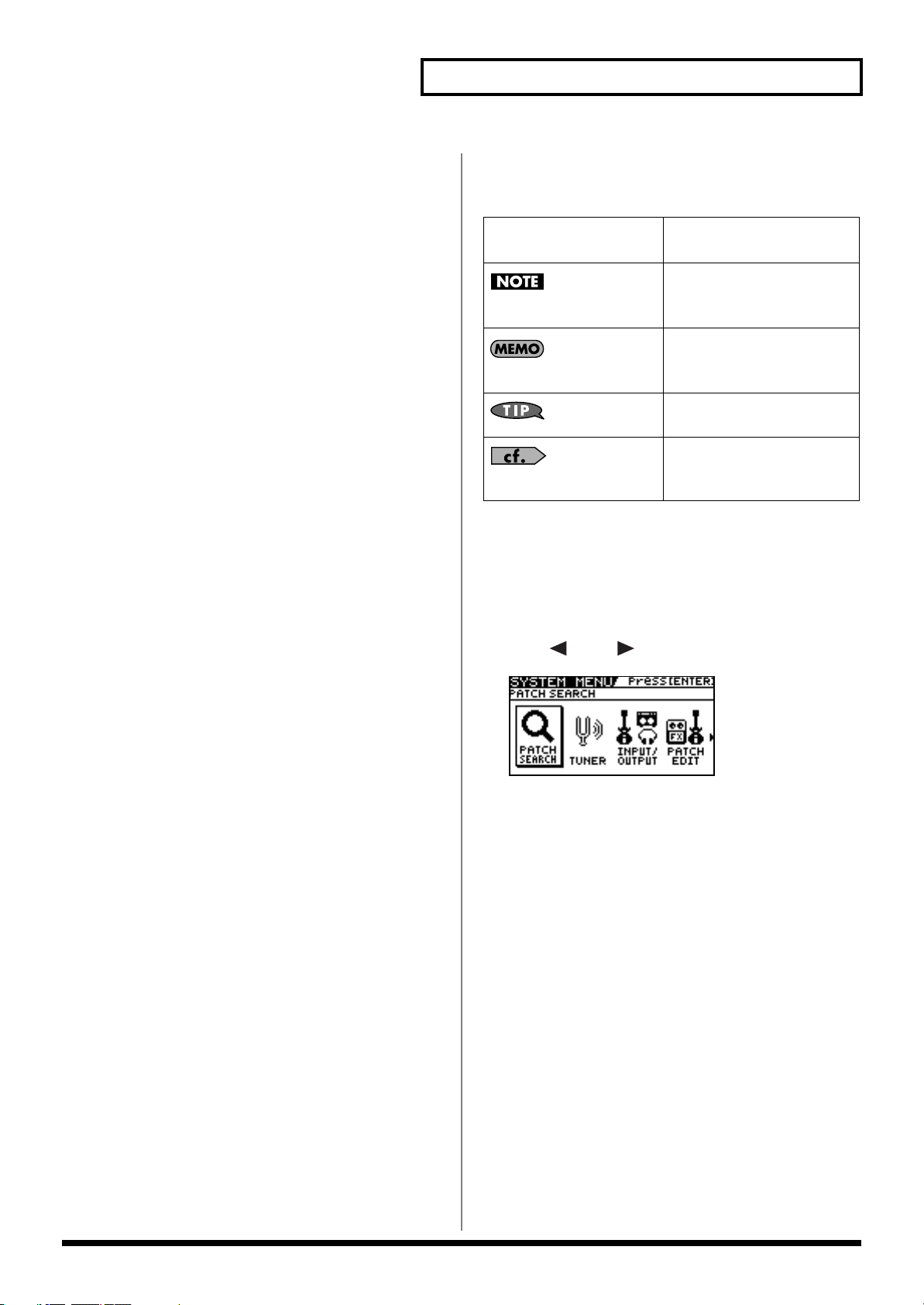
Printing Conventions and
icons in This Manual
Text or numerals enclosed
in square brackets [ ]
(p.**)
Indicate buttons.
[WRITE]
Indicates information that you
should be aware of when
using the GT-10B.
Indicates supplementary
information about an
operation.
Indicates information about a
convenient operation.
Indicates a reference page.
WRITE button
About the Explanations of
Procedures in the Text
• For selecting items like those shown in the screen view
below, the explanations describe how to make the
selection using the knobs, but you can also select the items
using [ ] and [ ] (the cursor buttons).
5
Page 6

Contents
IMPORTANT NOTES ...............................................................................4
Main Features........................................................................................10
Names of Things and What They Do...................................................11
Front Panel................................................................................................................................................. 11
Rear Panel.................................................................................................................................................. 13
Checking the Package Contents.................................................................................................. 13
Quick Guide...........................................................................................14
Getting Ready ........................................................................................................................................... 14
Playing Sounds .........................................................................................................................................16
Editing........................................................................................................................................................ 18
Basic Operation.............................................................................................................................. 18
Creating Sounds Based on Existing Patches .............................................................................18
Creating Sounds with Ease (EZ TONE)..................................................................................... 20
Chapter 1 Outputting Sounds..............................................................22
Making the Connections.......................................................................................................................... 22
Turning on the Power.............................................................................................................................. 24
The Icons in the Play Screen ........................................................................................................ 24
Switching the Play Screen............................................................................................................ 25
Adjusting the Output Level .................................................................................................................... 25
Making Settings for a Connected Device (Output Select) .................................................................. 26
Turning Off the Power............................................................................................................................. 27
Tuning the Bass (TUNER)....................................................................................................................... 27
Turning the Tuner Function On and Off ................................................................................... 27
About the Display During Tuning ............................................................................................. 27
How to Tune .................................................................................................................................. 28
Changing the Tuner Settings (Tuner Pitch)............................................................................... 28
Changing the Tuner Settings (Tuner Out)................................................................................. 29
Selecting a Tone (Patch Change) ............................................................................................................ 30
What is a Patch?............................................................................................................................. 30
Using the Pedal to Select the Patch.............................................................................................31
Using the Dial to Select the Patch ............................................................................................... 32
Separating Patches into Groups (CATEGORY)........................................................................ 32
Adjusting a Tone ...................................................................................................................................... 32
Chapter 2 Creating Sounds (Patch Edit).............................................33
Creating Sounds with Ease (EZ TONE) ................................................................................................ 33
Creating a Tone for the Song You Envision (Create)............................................................... 33
Adjusting the Tone (Edit)............................................................................................................. 33
Setting the Effects .....................................................................................................................................34
Turning an Effect On and Off...................................................................................................... 34
Setting the Effects Simply (Quick Setting)................................................................................. 35
Switching Between Knob View and List View ......................................................................... 35
Adjusting the Parameters............................................................................................................. 36
Changing the Connection Order of Effects (Effect Chain)...................................................... 37
Using Two Different Type Effects (Channel Select)................................................................. 39
Grouping Patches by Category (CATEGORY) ......................................................................... 40
Naming User Categories (CATEGORY NAME) ...................................................................... 41
Naming a Patch (PATCH NAME) ......................................................................................................... 42
Chapter 3 Saving a Tone ......................................................................43
Saving a Patch (PATCH WRITE) ...........................................................................................................43
Copying Patches (PATCH COPY) .........................................................................................................43
Exchanging Patches (PATCH EXCHANGE)........................................................................................ 44
6
Page 7

Initializing Patches (PATCH INITIALIZE)........................................................................................... 44
Storing Settings by Effect (User Quick Settings).................................................................................. 45
Swapping Effect Settings Between Channels .......................................................................................46
Chapter 4 Playing Sounds ...................................................................47
Setting the Functions of the Knobs of the Play Screen........................................................................ 47
Using Pedals to Control the Parameters ...............................................................................................48
Using the CTL/EXP Pedal With the Same Functions Assigned at All Times (Pedal Function)
Setting CTL/EXP Functions Individually in Each Patch (PEDAL FX) ................................. 49
Setting Each Controller Functions to Individual Patches (Assign)........................................ 51
Activating the Virtual Expression Pedal at the Start of Operations (Internal Pedal System)
Turning the Effects On and Off with the BANK/Number Pedals (Manual Mode)....................... 56
Switching to Manual Mode ......................................................................................................... 56
Switching Effects On and Off with the Pedals.......................................................................... 56
Assigning an Effect On/Off Switch to a Pedal ......................................................................... 57
Switching Settings with the Number Pedals........................................................................................ 58
Phrase Loop Play...................................................................................................................................... 59
What’s Phrase Loop? ....................................................................................................................59
Using the Phrase Loop ................................................................................................................. 59
Setting Phrase Loop ...................................................................................................................... 60
Overview of Phrase Loop Operation .........................................................................................62
....... 48
............ 55
Chapter 5 Making Global Settings.......................................................63
Making Settings Matched to the Connected Bass (Input Select) ....................................................... 63
Adjusting the Overall Sound to Match the Usage Environment (Global) ....................................... 64
Adjusting the Overall Tone (Global EQ) ...................................................................................64
Controlling the Overall Effect of the Noise Suppressor (Total Noise Suppressor)............. 65
Controlling the Overall Reverb Level (Total REVERB)........................................................... 66
Setting the Output Reference Level to Match the Connected Equipment (Main Out Level)
Adjusting the Output Level of the DIGITAL OUT Jack.......................................................... 68
Switching the SUB OUTPUT Jacks Signals ...............................................................................69
Adjusting the SUB OUTPUT Jacks Level .................................................................................. 70
Adjusting the Display Contrast (LCD Contrast).................................................................................. 71
Keeping Effect Sounds Playing After Patches Are Switched (Patch Change Mode) .....................72
Using the Identical Preamp Settings in All Patches (Preamp Mode) ............................................... 73
Using the System Preamp............................................................................................................ 73
Setting the System Preamp .......................................................................................................... 73
Saving the Current Preamp Setting As the System’s Preamp Setting................................... 74
Limiting the Banks That Can Be Switched (Bank Extent) .................................................................. 75
Setting the Timing Used for Switching Patches (Bank Change Mode) ............................................ 76
Having Values from an EXP Pedal Carried Over When Patches are Called Up (EXP Pedal Hold)
Switching How the Pedal Indicators Light (Pedal Indicate).............................................................. 78
Setting the Dial Function (Dial Function) ............................................................................................. 79
Restoring the Factory Settings (Factory Reset)..................................................................................... 80
Adjusting the EXP Pedal (Pedal Calibration)....................................................................................... 81
............ 67
............. 77
Chapter 6
What Can You Do with MIDI? ............................................................................................................... 83
Making the Settings for MIDI Functions............................................................................................... 84
Using the GT-10B with External MIDI Devices Connected
Operating From the GT-10B ........................................................................................................ 83
Remotely Controlling the GT-10B Using an External MIDI Device ...................................... 83
Setting the MIDI Receive Channel.............................................................................................. 84
Setting the MIDI Omni Mode......................................................................................................85
Setting the MIDI Transmit Channel ........................................................................................... 85
Setting the MIDI Device ID.......................................................................................................... 85
Setting the MIDI Sync Clock........................................................................................................ 85
Sending Program Change Messages .......................................................................................... 86
Sending EXP Pedal Operations as Control Change Messages ............................................... 86
Sending EXP Pedal Sw Operations as Control Change Messages......................................... 86
Sending External EXP Pedal Operations as Control Change Messages ...............................86
Sending CTL Pedal Operations as Control Change Messages............................................... 87
Sending External Footswitch Operations as Control Change Messages ..............................87
........83
7
Page 8

Setting the Correspondences Between Program Change Messages and Patches (Program Change Map)
Enabling/Disabling the Program Change Map Settings (MIDI Map Select)....................... 88
Setting the Program Change Map .............................................................................................. 88
Changing Patches Using Bank Select Messages .................................................................................. 89
Changing Patch Numbers on an External MIDI Device from the GT-10B........................... 89
Changing Patch Numbers on the GT-10B from an External MIDI Device........................... 90
Transmitting Data to an External MIDI Device (Bulk Dump)........................................................... 91
Making the Connections ..............................................................................................................91
Transmitting................................................................................................................................... 92
Receiving Data from an External MIDI Device (Bulk Load).............................................................. 93
Making the Connections ..............................................................................................................93
Receiving ........................................................................................................................................ 93
...... 88
Chapter 7
Before Connecting with USB .................................................................................................................. 94
Setting the USB Functions....................................................................................................................... 96
Recording the GT-10B’s Output with a Computer.............................................................................. 98
Applying GT-10B Effects to a Computer’s Audio Playback .............................................................. 99
Using the GT-10B Connected to a Computer Via USB
Installing and Setting the USB Driver........................................................................................ 94
Exchanging MIDI Messages between the Computer and the GT-10B .................................. 94
Switching the Driver Mode ......................................................................................................... 95
Setting the Digital Audio Signal Input and Output................................................................. 96
Setting the Direct Monitor ...........................................................................................................97
Controlling the Direct Monitor Setting from a Computer ...................................................... 98
.........94
Chapter 8 Parameters Guide..............................................................100
COMPRESSOR/LIMITER..................................................................................................................... 100
OD/DS
(Overdrive/Distortion).......................................................................................................................... 101
PREAMP .................................................................................................................................................. 102
Preamp Settings........................................................................................................................... 102
Speaker Settings .......................................................................................................................... 104
EQ (Equalizer)......................................................................................................................................... 105
FX-1/FX-2 ................................................................................................................................................ 105
T.WAH (Touch Wah).................................................................................................................. 106
AUTO WAH (Auto Wah) ..........................................................................................................106
SUB WAH..................................................................................................................................... 107
SUB COMP (Sub Compressor).................................................................................................. 107
SUB LIMITER .............................................................................................................................. 108
GRAPHIC EQ (Graphic Equalizer) .......................................................................................... 108
PARA EQ (Parametric Equalizer)............................................................................................. 108
ENHANCER ................................................................................................................................ 109
TONE MODIFY........................................................................................................................... 109
BASS SIM. (Bass Simulator)....................................................................................................... 109
SLOW GEAR................................................................................................................................ 110
DEFRETTER................................................................................................................................. 110
BASS SYNTH............................................................................................................................... 110
OCTAVE....................................................................................................................................... 111
PITCH SHIFTER.......................................................................................................................... 111
HARMONIST ..............................................................................................................................112
SOUND HOLD............................................................................................................................ 113
PHASER........................................................................................................................................ 114
FLANGER ....................................................................................................................................114
TREMOLO.................................................................................................................................... 115
ROTARY....................................................................................................................................... 115
UNI-V............................................................................................................................................ 115
PAN............................................................................................................................................... 115
SLICER.......................................................................................................................................... 116
VIBRATO...................................................................................................................................... 116
RING MOD. (Ring Modulator) ................................................................................................. 117
HUMANIZER.............................................................................................................................. 117
2X2 CHORUS............................................................................................................................... 118
SUB DELAY ................................................................................................................................. 118
8
Page 9

DELAY ..................................................................................................................................................... 119
DELAY Common Parameters ...................................................................................................119
Pan................................................................................................................................................. 120
Dual-S, Dual-P, Dual-L/R.......................................................................................................... 120
Warp.............................................................................................................................................. 120
Modulate ...................................................................................................................................... 120
CHORUS.................................................................................................................................................. 121
REVERB ................................................................................................................................................... 121
MASTER .................................................................................................................................................. 122
MASTER ....................................................................................................................................... 122
MASTER BPM/KEY................................................................................................................... 122
PEDAL FX .................................................................................................................................... 122
ASSIGN 1–8.................................................................................................................................. 126
SEND/RETURN.......................................................................................................................... 131
AMP CONTROL .........................................................................................................................132
NS1/NS2 (Noise Suppressor) ................................................................................................... 132
CH.SELECT (Channel Select).................................................................................................... 133
EZ TONE ................................................................................................................................................. 134
STEP1: TONE............................................................................................................................... 134
STEP2: DRIVE.............................................................................................................................. 134
SYSTEM ................................................................................................................................................... 134
TUNER.......................................................................................................................................... 134
INPUT/OUTPUT........................................................................................................................ 134
PHRASE LOOP ........................................................................................................................... 135
MANUAL MODE SETTING ..................................................................................................... 136
PLAY OPTION ............................................................................................................................ 136
CONTROLLER ............................................................................................................................ 137
LCD ............................................................................................................................................... 139
MIDI .............................................................................................................................................. 139
USB................................................................................................................................................ 140
OUTPUT SELECT................................................................................................................................... 141
Appendices..........................................................................................142
Signal Flow .............................................................................................................................................. 142
MIDI Implementation Chart................................................................................................................. 143
Specifications........................................................................................................................................... 144
Error Messages........................................................................................................................................ 145
Troubleshooting...................................................................................................................................... 145
Problems with the sound ........................................................................................................... 145
Other Problems............................................................................................................................ 146
Index.....................................................................................................147
9
Page 10

Main Features
Multi-Effects Processor Designed for Bass, Packed with the Latest
Technologies
The GT-10B’s original high-performance processors put BOSS’s wealth of bass expertise in a single package.
BOSS COSM effects have been precision-tuned to fully express all of the subtle fingering nuances that are characteristic of the
bass. It can truly be said that this is the definitive bass multi-effects processor.
Create Tones Intuitively with EZ TONE
The EZ TONE provides an innovative user interface that enables you to create your own tones with absolutely no special
knowledge of effect parameters needed.
Sound making on the EZ TONE is truly intuitive. EZ TONE shows you the way to create the sound with both graphical icons and
intuitive terms such as “SOFT” or “HARD.” Choose the basic sound you want according to the music genre, song imagery,
performance-style. Then you can shape the sound by just moving the cursor on the TONE GRID toward “SOFT” or “HARD.”
Now everyone can easily create his or her own tones the instant a sonic image comes to mind.
Phrase Loop Feature
The Phrase Loop feature lets you record and play loop performances, whereby you continue adding new sounds as the loop
plays.
The unit provides up to 38 seconds of recording time, which lets you switch effects as you continue to layer additional bass lines.
You can also take phrases recorded beforehand without effects and then apply the perfect tone, adding the effects as you play
back the phrase.
A Wide Variety of Tones with Parallel Chain
The GT-10B includes a “Parallel Chain” function that allows you to split the “chain”—the signal path—into two independent
chains, with full freedom to arrange effects in each chain in any order you want.
This feature also enables you to change the relative balance of sounds from the two chains according to volume or pitch, and
provides you with even greater precision in creating tones.
Works Like a Compact Effects Processor
Operating the GT-10B is like using compact effects processors. It’s easy to make super-fast tone adjustments, even in the middle of
live performances. Just select an effects type, then directly adjust the four optimal parameters with the front-panel knobs. Of
course, you can also switch the display to show all effect parameters to create tones with even more exacting detail.
Equipped with XLR Balanced Output Jacks
The GT-10B features two XLR type output jacks, enabling you to connect to PAs and recording decks.
High-Visibility Indicators
Foot pedal indicators and other lights all utilize brightly lit LEDs. Clearly visible in any situation, whether it be in a live outdoor
concert or up on a pitch-black stage, these indicators help ensure accurate operation.
10
Page 11
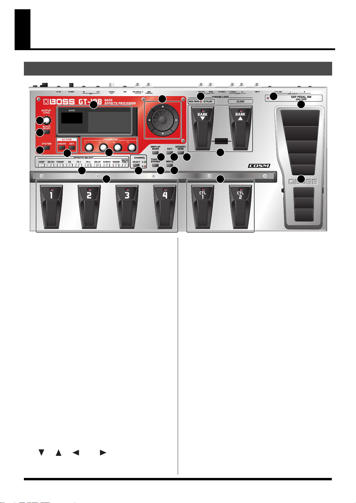
Names of Things and What They Do
Front Panel
1
2
3
4
5
8
6
9
17
1.
Display
Various information about the GT-10B is shown here.
The display screen on the left side shows the bank
number.
2.
OUTPUT LEVEL Knob
This adjusts the volume level at the OUTPUT jack and
the PHONES jack.
3.
OUTPUT SELECT Button
This adjusts the characteristics of the output from the GT10B to match the type of equipment that is connected (p. 26).
4.
SYSTEM Button
This makes global settings mainly, for the GT-10B (p. 63).
5.
EZ TONE
CREATE Button
This makes it easy to create tones based on the musical
genre and the feel of the song you have in mind (p. 33).
EDIT Button
This provides a simple way to modify tones (p. 33).
6.
Parameter Knobs P1 Through P4
These change the values of the parameter shown on the
display.
7.
Dial
This switches patches and modifies values.
[ ], [ ], [ ], and [ ] (Cursor Buttons)
These move the onscreen cursor up, down, or to the left
or right.
7
10 11
13 14
16
PHRASE LOOP
ON / OFF
BPM
12
15
21
18
8.
EFFECTS SELECT
Use these buttons to switch effects on or off, or to change
their settings (p. 34). When an effect is switched on, the
button’s indicator lights up; the indicator goes out when
the effect is off.
* [MASTER/PEDAL FX] does not light up.
COMP (Compressor) Button
OD/DS (Overdrive/Distortion) Button
PREAMP Button
EQ (Equalizer) Button
FX-1 Button
FX-2 Button
DELAY Button
CHORUS Button
REVERB Button
MASTER/PEDAL FX (Master/Pedal Effect) Button
9.
SELECT Button
These switch between the A and B channels for the
Effects.
10.
DISPLAY MODE Button
Allows you to change the way things are shown in the
display (p. 25).
11.
EXIT Button
Use this to go back to the previous screen or to cancel an
operation.
20
19
11
Page 12

Names of Things and What They Do
12.
CATEGORY/ENTER Button
Use this button for the following operations:
• When executing an operation
• When selecting patches arranged by category (p. 32)
• When doing tap input for MASTER BPM (p. 122) or Delay Time (p. 119)
13.
TUNER/BYPASS Button
Press to use the tuner features (p. 27).
14.
WRITE Button
Use this to store patch settings in memory, or to replace
or copy settings (p. 43).
15.
BANK Pedals
Use these when switching patch banks (p. 31) or
performing operations with phrase loops (p. 59).
You can switch a phrase loop on or off by depressing the two BANK pedals
at the same time (
16.
PHRASE LOOP (p. 59)
REC/DUB (Recording/Overdubbing) Indicator
This lights steadily when you’re recording or
overdubbing a phrase, and flashes during recording
standby.
PLAY Indicator
This lights up while phrase playback is in progress.
p. 59
).
17.
Number Pedals 1 through 4
These switch the patch number (p. 31).
18.
CTL (Control) Pedals 1 and 2
These can be used to control a variety of functions you
assign, such as the A and B channels for the PREAMP (p.
102) or switching the Tuner on or off (p. 48).
19.
EXP (Expression) Pedal
Controls volume, wah, and other parameters (p. 48).
When operating the EXP Pedal, be careful not to get your fingers pinched
between the movable part and the panel. In places with small children, an
adult should provide supervision and guidance until the child is capable of
following all the rules essential for the safe operation of the unit.
When “EXP1” is shown in the display for a parameter, indicates the GT10B’s EXP pedal.
20.
EXP PEDAL SW (EXP Pedal Switch)
The switch is turned on or off by firmly pressing on the
toe of the EXP Pedal.
21.
EXP PEDAL SW ON/OFF
(EXP Pedal Switch On/Off) Indicator
This lights up when the feature controlled by the EXP
PEDAL SW is on and goes out when the controlled
feature is off.
12
Page 13

Rear Panel
Names of Things and What They Do
16
1
1.
SUB OUTPUT Jacks L, R
These balanced output jacks use XLR type connectors.
2.
GND LIFT Switch
You can disconnect the SUB OUTPUT jacks’ No. 1 pin
from the GT-10B’s ground.
Switch this to LIFT if a ground loop or similar problem is
causing output of hum or noise. Normally, this is set to
GND.
3.
INPUT Jack
The bass is connected here.
4.
OUTPUT Jacks L/MONO, R
Connect to your amp, mixer, or such device.
5.
PHONES Jack
Connect headphones here.
Tonal adjustments for monitoring are applied when headphones are
connected to the PHONES jack.
6.
EXT LOOP SEND RETURN Jacks
Connect to external effects processor or amp.
7.
AMP CONTROL Jack
When using the AMP CONTROL function (p. 132),
connect to the jack used for switching bass amp
channels.
8.
EXP PEDAL 2/CTL 3, 4 Jack
Connect an optional expression pedal (such as the
Roland EV-5) or footswitch (such as the BOSS FS-6) here
(p. 22).
9.
USB Connector
Use a USB cable to connect a computer to this connector
and enable exchange of data between the GT-10B and the
computer (p. 94).
10.
DIGITAL OUT Jack
Outputs digital audio signals (p. 68).
2
3
4
5
6
7
8
11.
MIDI IN/OUT Connectors
Connect an external MIDI device to these connectors to
transmit and receive MIDI messages (p. 83).
12.
POWER Switch
Turns the power on and off.
13.
DC IN (AC Adaptor) Jack
Connect the included AC adaptor here.
* To prevent damaging the GT-10B, please be sure not to use
any AC adaptor other than the one included with the GT-10B.
14.
Cord Hook
Hook the AC adaptor cord here to prevent the adaptor
plug from being disconnected (p. 22).
* Disconnecting the AC adaptor while the GT-10B is in use may
result in corruption of important data.
15.
Security Slot ( )
Connect a commercially available anti-theft security
cable here.
http://www.kensington.com/
16.
Grounding Terminal
Connect the ground cable here.
Before using the grounding terminal, carefully read the sections entitled:
Notes in the “Making the Connections” (p. 23).
10
9
11
12 13
14
15
Checking the Package Contents
The GT-10B comes with the following items. After opening
the package, please check all items. If any items are missing,
please contact the retailer from whom this product was
purchased.
• GT-10B
• AC Adaptor (Roland PSB-1U)
• Owner’s Manual (This document)
• Roland Service (Information Sheet)
13
Page 14
Quick Guide
The Quick Guide describes required settings and basic operations. For detailed descriptions of operations,
refer to the explanations in chapter 1 and after.
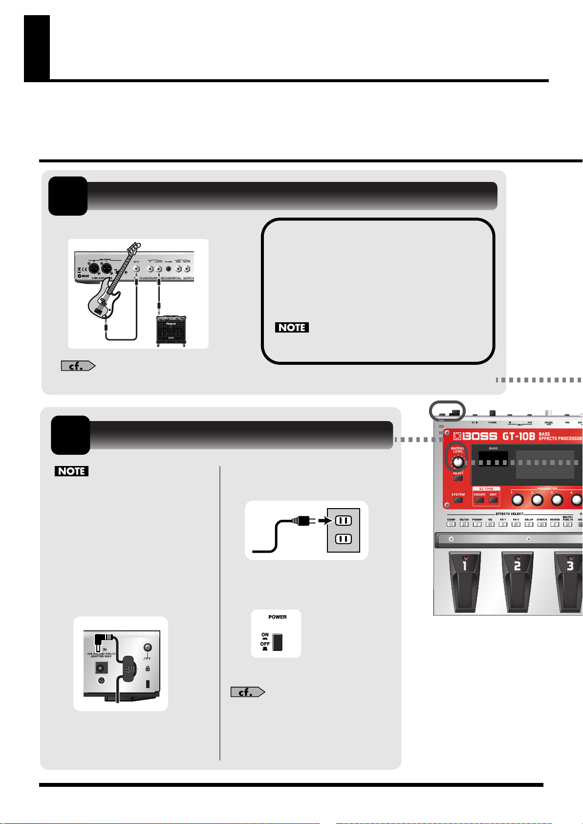
Getting Ready
1
1.
Connect the bass and the bass amp.
For detailed information on how to make the connections, refer to “Making the Connections” (p. 22).
2
Once the connections have been
completed, turn on power to your
various devices in the order specified.
By turning on devices in the wrong
order, you risk causing malfunction
and/or damage to speakers and other
devices.
Connect the Bass and Amp
Before turning on the power, confirm the
following.
Bass Amp
Bass
Turn On the Power
2.
Plug the AC adaptor into a
power outlet.
• Are all external devices properly connected?
• Is the volume on the GT-10B, your amp, and
all other connected devices turned down to
the minimum level?
Raise the amp volume only after turning on the power
to all connected devices.
1.
Insert the DC plug on the
AC adaptor into the DC IN
jack on the GT-10B.
14
3.
Use the POWER switch to
switch on the power.
4.
Power up the bass amp.
For information on how to switch off
the power, refer to “Turning Off the
Power” (p. 27).
Page 15
OUTPUT
External Effector
Bass Amp
Bass
INPUT
INPUT
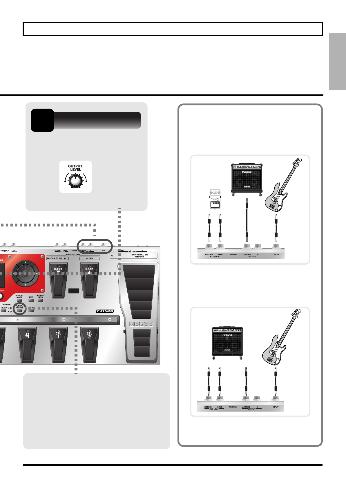
3
Adjust the Volume
Quick Guide
Examples of Connections Using
the SEND/RETURN Jacks
Quick Guide
Use the OUTPUT LEVEL knob to
adjust the volume level.
PHRASE LOOP
ON / OFF
BPM
Example 1: Using an External Effects Unit
This enables use as one of the GT-10B’s effects.
Example 2: Using Send and Return on the
bass Amp
This allows you to switch between use of the
GT-10B and the bass amp’s preamp.
Tune the Bass
Each press of the TUNER/BYPASS button
switches the Tuner feature on or off.
Switching on the Tuner feature enables direct
output of input sounds (bypass), and lets you
tune the bass while in this state. For more
information, refer to “Tuning the Bass
(TUNER)” (p. 27).
Bass Amp Bass
SEND
INPUT
* When you’re making connections using the SEND/
RETURN jacks, you also need to make settings for the
“SEND/RETURN” (p. 131).
RETURN
15
Page 16
Quick Guide
Playing Sounds
Once you’ve finished getting ready to play, try playing sounds as you operate the GT-10B.
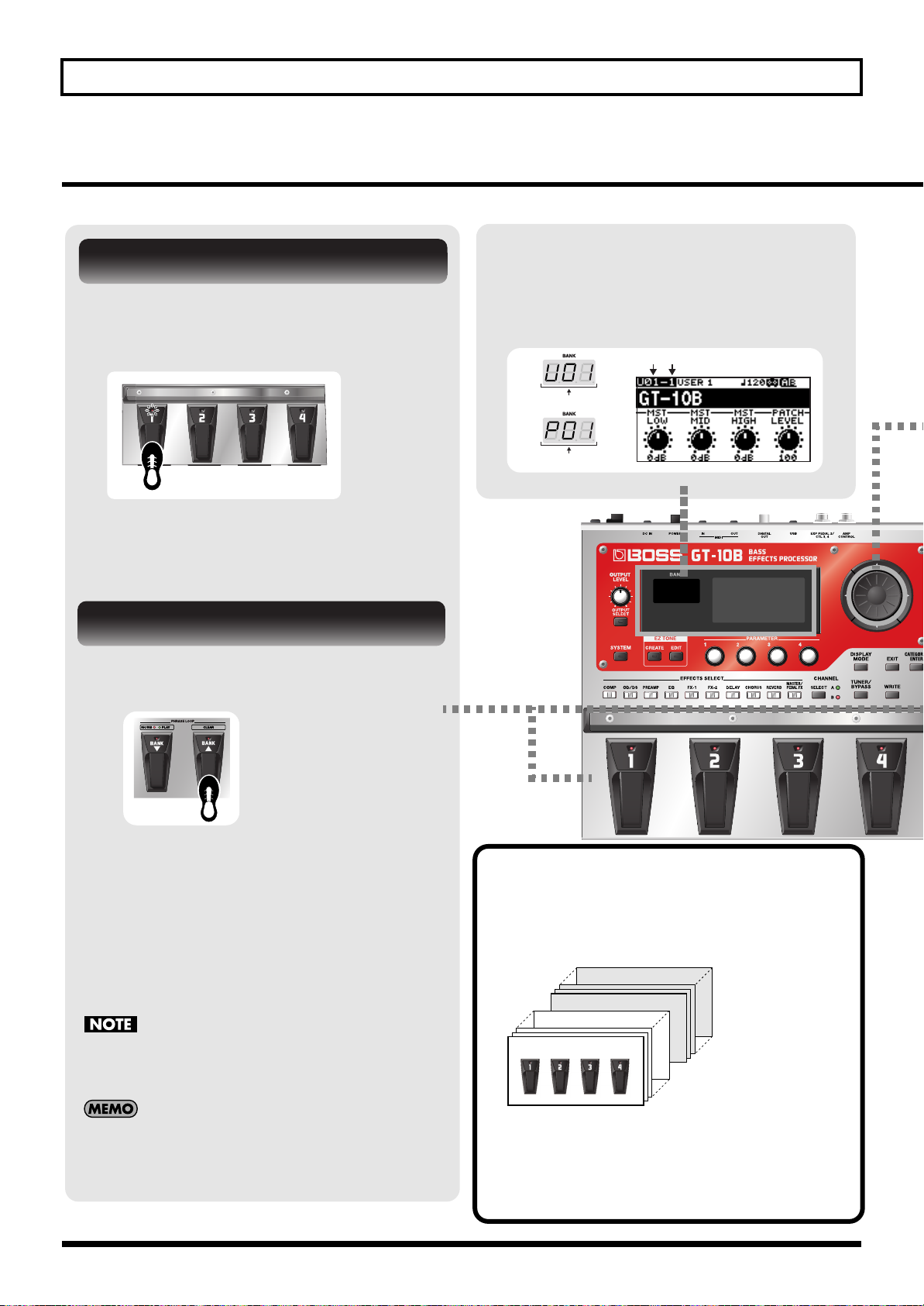
About the Bank and Number Display
Choosing a Patch in the Current Bank
Choose the patch you want to use by
depressing the corresponding number
pedal.
The display on the left side shows the bank,
and the display on the right side shows the
bank and patch number.
Bank Number
User Bank
Preset Bank
The indicator for the number pedal you pressed
lights up and the patch is switched.
Choosing a Patch in a Different Bank
1.
Press the BANK pedals to select the
desired bank.
The GT-10B stands by for specification of
the patch number, and the number pedal
indicators blink.
2.
Choose the patch you want to use by
depressing the corresponding number
pedal.
The indicator for the number pedal you
pressed lights up and the patch is switched.
If you’re not at the Play screen (p. 24), you won’t be able
to switch patches. Press the [EXIT] button to go back to
the Play screen, then choose the patch.
What is a Patch?
A combination (or set) of effects together with a
group of parameter settings is called a “patch.”
The GT-10B can store 400 different patches in memory,
organized by bank and number as shown below.
User Bank 01
BPM
Preset Bank 50
Preset Bank 01
User Bank 50
You can also use the BANK pedals to operate the Phrase
Loop feature. Phrase Loop is a feature that lets you
record a performance and play it back as a loop. For
more information, refer to “Phrase Loop Play” (p. 59).
16
Patches include User patches, which you can use to
save the settings for newly created effects, and Preset
patches, for which modified settings cannot be saved.
For more information, refer to “Selecting a Tone
(Patch Change)” (p. 30).
Page 17
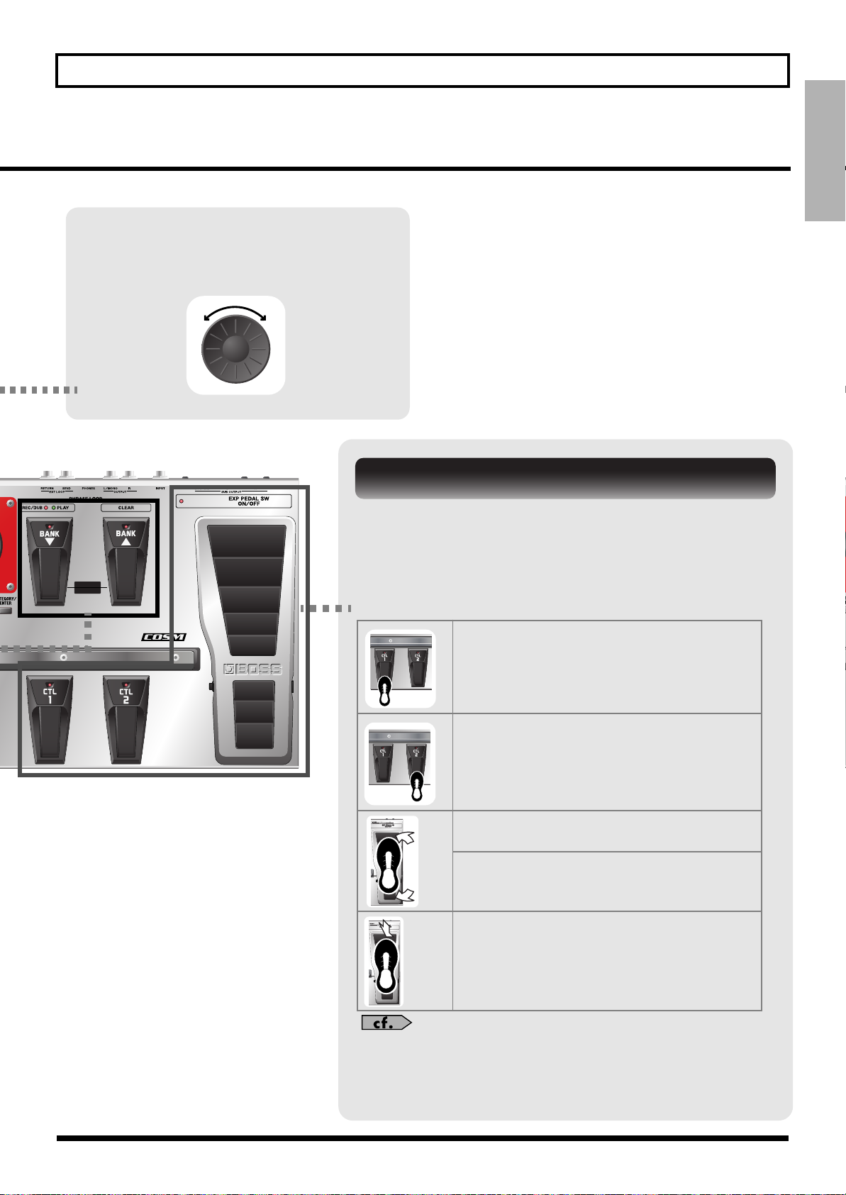
Switch the Patch with the Dial
When you’re at the Play screen (p. 24),
turning the dial switches the patch.
Quick Guide
Quick Guide
Working with Effects Using the Pedals
The EXP Pedal and the CTL 1 and 2 pedals can be set to use in
switching effects on or off for individual patches, use as a volume
pedal, and other such operations.
PHRASE LOOP
ON / OFF
BPM
Executing these operations during a performance lets you modify
the sound more effectively.
Press the CTL 1 pedal.
The CTL1 pedal function is switched on.
(The indicator for the CTL 1 pedal lights up.)
Press a second time to switch off.
(The indicator for the CTL 1 pedal goes out.)
Press the CTL 2 pedal.
The CTL2 pedal function is switched on.
(The indicator for the CTL 2 pedal lights up.)
Press a second time to switch off.
(The indicator for the CTL 2 pedal goes out.)
Press the toe of the EXP Pedal.
The EXP Pedal value rises.
Press the heel of the EXP Pedal.
The EXP Pedal value decreases.
Press the toe of the EXP Pedal firmly.
The EXP PEDAL SW function is switched on.
(The EXP PEDAL SW ON/OFF indicator lights up.)
Press firmly a second time to switch off.
(The EXP PEDAL SW ON/OFF indicator goes out.)
You can assign the parameters you want to the EXP Pedal, EXP PEDAL
SW and the CTL 1 and 2 pedals and operate them accordingly. For more
information, refer to “Using Pedals to Control the Parameters” (p. 48).”
17
Page 18
Quick Guide
Editing
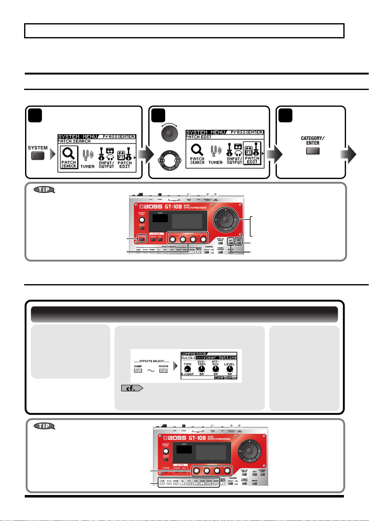
Basic Operation
This describes the basic operations you use when editing settings.
Access the System Menu
screen.
Choose the menu item.
2 31
The setting screen
for the selected
item appears.
or
* In this example, "PATCH EDIT" icon is selected.
Buttons and Knobs You Use
These set the parameter value.
·
· Changes the page.
This displays the System Menu.
Sets the parameter value.
· Chooses an item.
This confirms the selected item.
BPM
This quits making settings.
Creating Sounds Based on Existing Patches
Let’s try creating a new sound based on a patch whose sound is close to what you want to make.
Switching Effects On and Off
1.
Choose a patch
whose sound is
close to the
sound you want
to create (p. 16).
Buttons and Knobs You Use
These set the parameter value.
These choose the effect.
2.
Choose the effect you want to switch on
or off.
For more information about each parameter, refer to
“Chapter 8 Parameters Guide” (p. 100).
3.
Again press the
button you
pressed in step 2.
The effect is
switched on or off.
Effect on: button
illuminated
Effect off: button
extinguished
BPM
18
Page 19
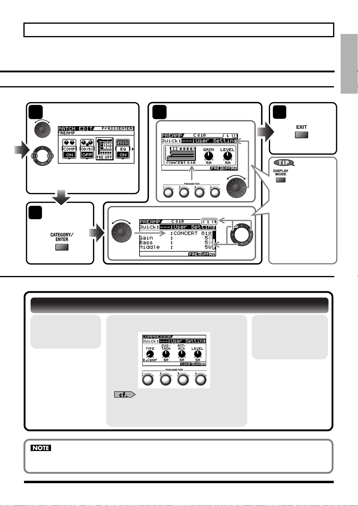
Quick Guide
Quick Guide
Choose the menu item.
or
* Depending on the choosing item in Step 2,
this screen may not appear.
The setting screen
5
for the selected
item appears.
Example 2
Change the parameter
6
settings.
Example 1
74
Only the major
parameters are shown
in Knob View, you can
adjust the parameters
quickly. If you want to
have all parameters
appear, switch to List
View.
Quit the
settings.
(Go back to the
previous screen.)
Each press this
button switches
between Knob
View and List
View.
Adjusting Effect Parameters
1.
Switch on the
effect you want
to adjust.
If you switch patches, all settings that have been made will be lost. To save the sound you’ve created, carry out the Write
procedure (p. 43).
2.
Adjust the parameters for the effect.
For more information about each parameter, refer
to “Chapter 8 Parameters Guide” (p. 100).
3.
Repeat steps 1
and 2 until you
obtain the sound
you want.
19
Page 20
Quick Guide
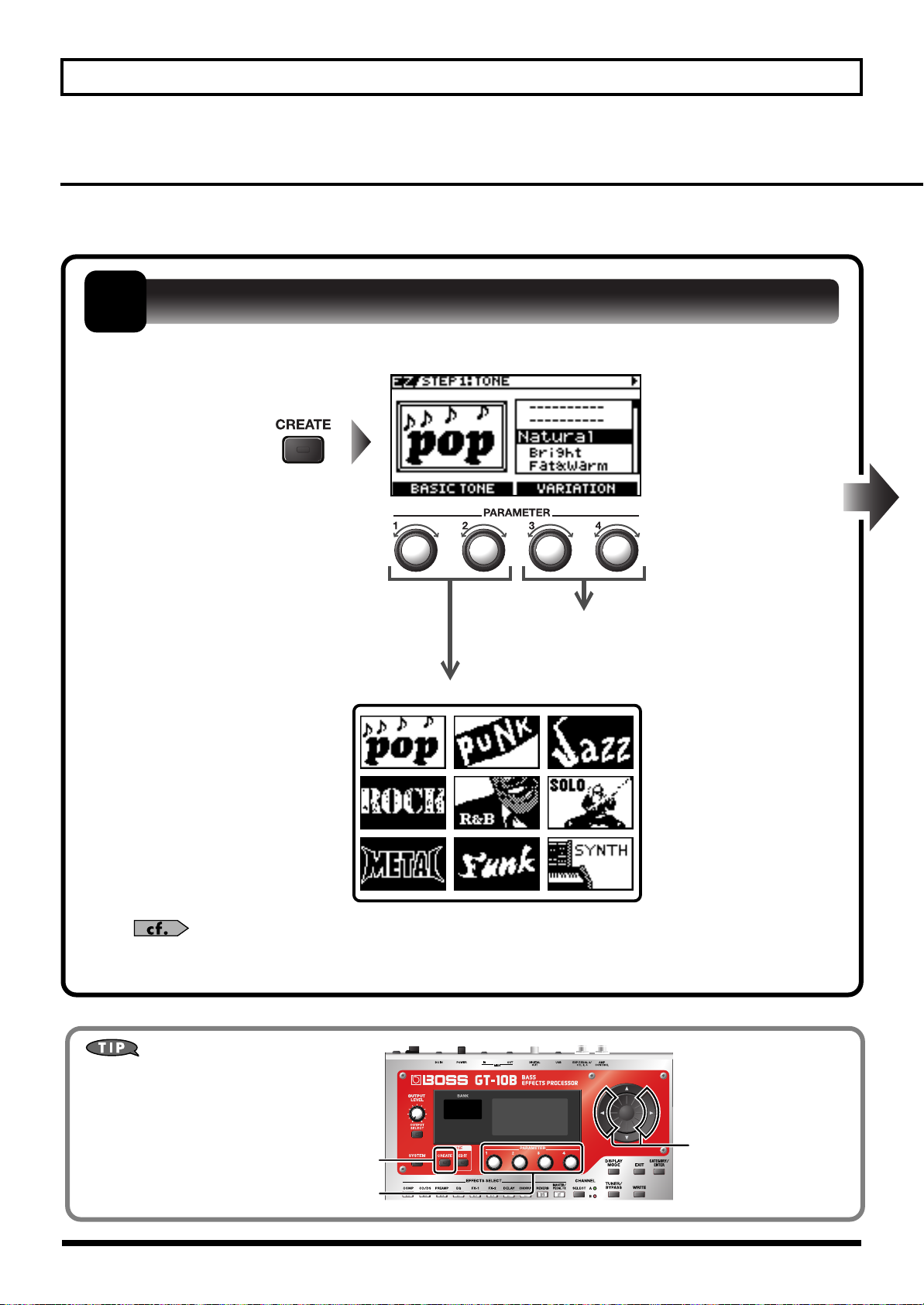
Creating Sounds with Ease (EZ TONE)
Using the EZ Tone feature (p. 33) lets you quickly find settings close to the musical genre and feel of the
song you want to create, and enables you to create the sound easily. Let’s try creating sounds using EZ Tone.
1
Use the basic tones and variations to choose the musical genre and the feel of the song.
Choose the Basic Tone
Variations
Basic Tones
20
For more information about each parameter, refer to “STEP1: TONE” (p. 134).
Buttons and Knobs You Use
These change the page.
This starts the EZ Tone feature.
BPM
These set the parameter values.
Page 21
Quick Guide
Quick Guide
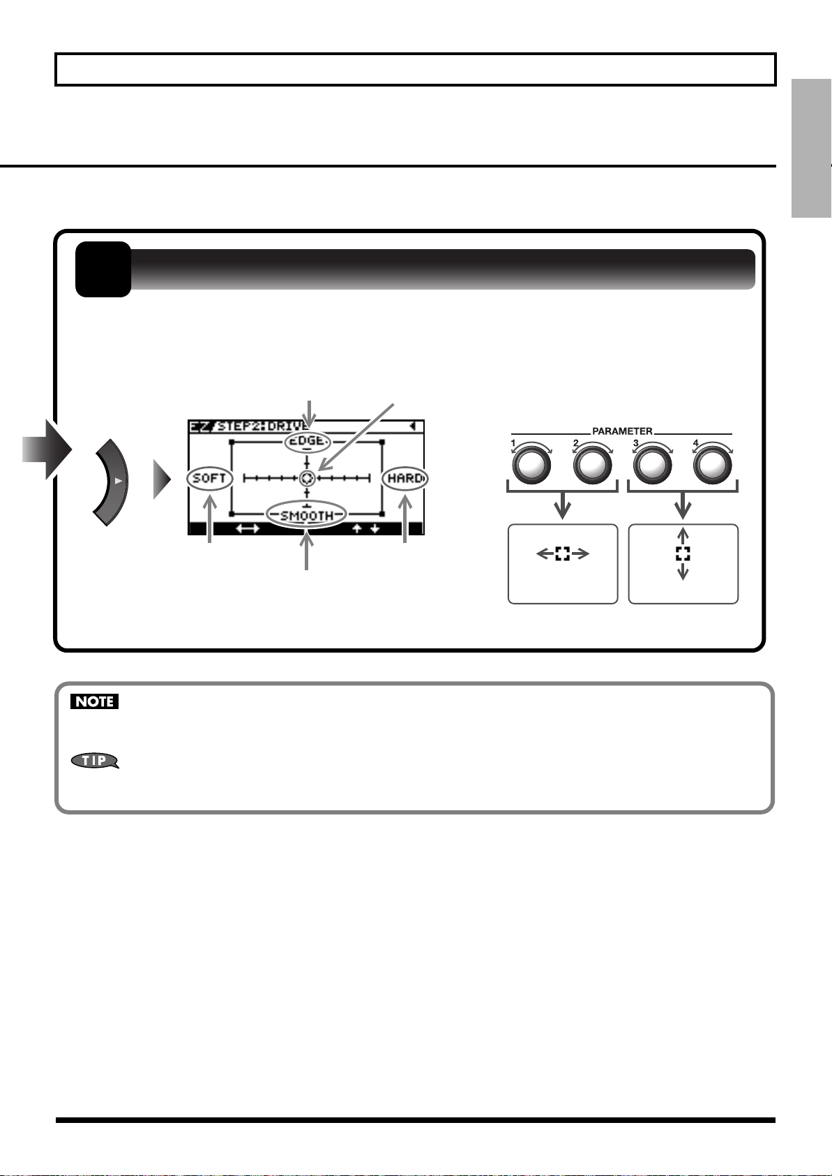
2
Using Tone Grid, adjust the distortion or compression until you get the sound you want.
Adjust the Distortion/Compression
Distortion/Compression:
Soft
Tone: Smooth
Tone: Edge
Cursor movement
Distortion/Compression:
Hard
Horizontal Vertical
Cursor movement
If you switch patches, you’ll lose all the settings you’ve made. To save the sound you’ve created, carry out the Write
procedure (p. 43).
You can take parameters you’ve adjusted with EZ TONE CREATE and fine-tune them further using EZ TONE EDIT or
parameter operations. For more information, refer to “Adjusting the Tone (Edit)” (p. 33).
21
Page 22
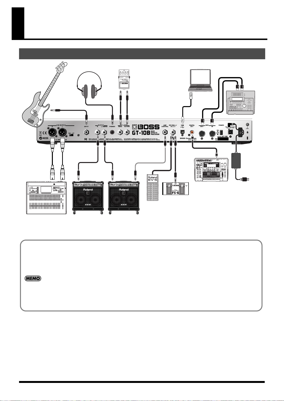
Chapter 1 Outputting Sounds
INPUT OUTPUT
OUT IN
Mixer
Bass Amp
Stereo
Headphone
External EffectorBass Computer
MIDI Sequencer
AC Adaptor
(PSB-1U)
Digital Recorder etc.
Expression Pedal (Roland EV-5, etc.)
or
Footswitch (BOSS FS-6, etc.)
Making the Connections
Connecting Directly to a Recording Mixer or PA Mixer (XLR Balanced Output)
The GT-10B features balanced outputs that utilize SUB OUTPUT jacks (XLR connectors). Although direct boxes are generally
used to connect bass (effects processor) outputs to mixers in concert halls and recording studios, you can connect the GT-10B
directly to the mixer, which lets you avoid degradations in the sound quality, as well as any additional problems that might
occur as the result of connecting multiple devices.
• The SUB OUTPUT level cannot be adjusted with the OUTPUT LEVEL knob.
• The OUTPUT SELECT function (p. 26) affects sounds from the OUTPUT jacks. The output from the SUB OUTPUT jacks will always be equivalent to the
sound that is output when the LINE/PHONES setting is used.
22
Page 23
•
BOSS FS-6
BA
PCS-31 cable
To CTL3,4 jack To CTL3,4 jack To CTL3,4 jack
White Red White Red
BOSS
FS-5U
(CTL3)
BOSS
FS-5U
(CTL4)
(CTL3) (CTL4)
(CTL4) (CTL3)
To prevent malfunction and/or damage to speakers or other devices,
always turn down the volume, and turn off the power on all devices
before making any connections.
• Raise the amp volume only after turning on the power to all connected
devices.
• When connection cables with resistors are used, the volume level of
equipment connected to the INPUT jack may be low. If this happens,
use connection cables that do not contain resistors.
• When outputting in mono, connect the cable to the OUTPUT L/MONO
jack.
• Use only the specified expression pedal (Roland EV-5 or BOSS FV-500L;
sold separately). By connecting any other expression pedals, you risk
causing malfunction and/or damage to the unit.
• Depending on the circumstances of a particular setup, you may
experience a discomforting sensation, or perceive that the
surface feels gritty to the touch when you touch this device,
microphones connected to it, or the metal portions of other
objects, such as basses. This is due to an infinitesimal electrical
charge, which is absolutely harmless. However, if you are concerned
about this, connect the ground terminal (see figure) with an external
ground. When the unit is grounded, a slight hum may occur, depending
on the particulars of your installation. If you are unsure of the
connection method, contact the nearest Roland Service Center, or an
authorized Roland distributor, as listed on the “Information” page.
Unsuitable places for connection
· Water pipes (may result in shock or electrocution)
· Gas pipes (may result in fire or explosion)
· Telephone-line ground or lightning rod
(may be dangerous in the event of lightning)
• Place the AC adaptor so the side with the indicator (see illustration) faces
upwards and the side with textual information faces downwards.
The indicator will light when you plug the AC adaptor into an AC outlet.
Chapter 1 Outputting Sounds
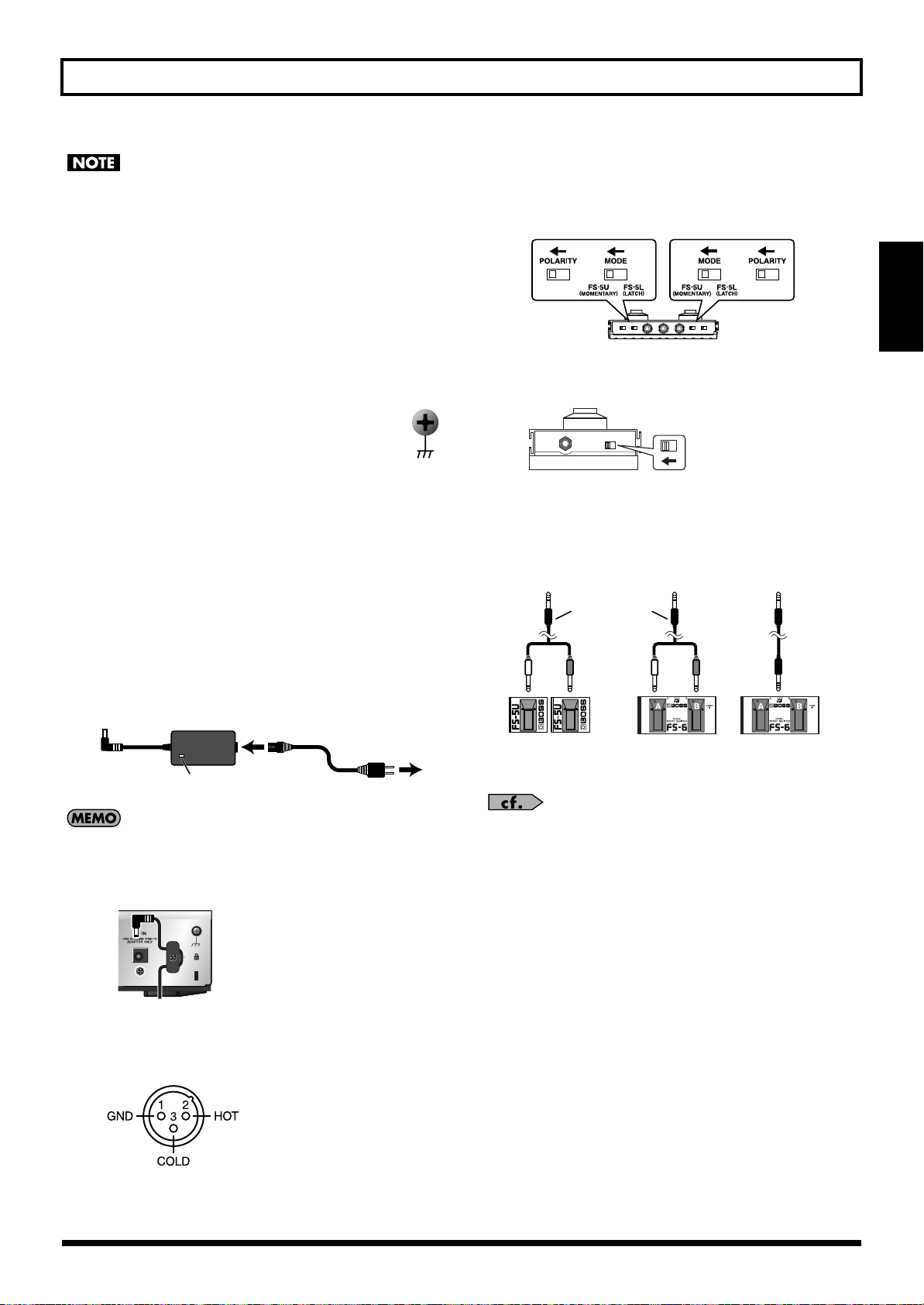
• When connecting an expression pedal to the EXP PEDAL2/CTL 3,4 jack, set the
minimum volume for the connected expression pedal to the “MIN” position.
• When connecting a BOSS FS-6 footswitch (optional) to the EXP PEDAL 2/CTL
3,4 jack, set the MODE switch and POLARITY switch as shown below.
Chapter
1
• When connecting a BOSS FS-5U footswitch (optional) to the EXP
PEDAL 2/CTL 3,4 jack, set the POLARITY switch as shown below.
Porarity Switch
• You can use the special (optional Roland) PCS-31 connector cord to
connect two footswitches.
• When a BOSS FS-6 footswitch (optional) is connected to the CTL3,4 jack
with an optional connection cable (stereo 1/4” phone – stereo 1/4” phone),
pedal switch B operates according to the CONTROL 3 settings, and pedal
switch A operates according to the CONTROL 4 settings.
AC Adaptor
Indicator
• To prevent the inadvertent disruption of power to your unit (should the
plug be pulled out accidentally), and to avoid applying undue stress to
the AC adaptor jack, anchor the power cord using the cord hook, as
shown in the illustration.
• This instrument is equipped with balanced (XLR) type connectors.
Wiring diagrams for these connectors are shown below. Make
connections after first checking the wiring diagrams of other equipment
you intend to connect.
Power Cord
AC Outlet
•
When using the unit with an expression pedal or a footswitch (the optional
FS-6 or FS-5U) connected to the EXP PEDAL 2/CTL 3,4 jack, make the
settings given on “Using Pedals to Control the Parameters” (p. 48).
• For more on using the AMP CONTROL jack, refer to “AMP CONTROL”
(p. 132).
23
Page 24
Chapter 1 Outputting Sounds
Turning on the Power
Before turning on the power, confirm the following.
• Are all external devices properly connected?
• Is the volume on the GT-10B, your amp, and all other connected devices turned down to the minimum level?
Once the connections have been completed, turn on power to your various devices in the order specified. By turning on devices in the wrong order, you risk causing
malfunction and/or damage to speakers and other devices.
• Upon power-up, the patch most recently
The display changes, showing the following.
pears at this point is called the “
Play screen
The screen that ap-
.”
1.
2.
Turn on the power to any external effects processors → the bass amp (power amp).
selected when the power was last turned off is
selected.
• This unit is equipped with a protection circuit.
A brief interval (a few seconds) after power up
is required before the unit will operate
normally.
• The explanations in this manual include
illustrations that depict what should typically be
shown by the display. Note, however, that your
unit may incorporate a newer, enhanced version
of the system (e.g., includes newer sounds), so
what you actually see in the display may not
always match what appears in the manual.
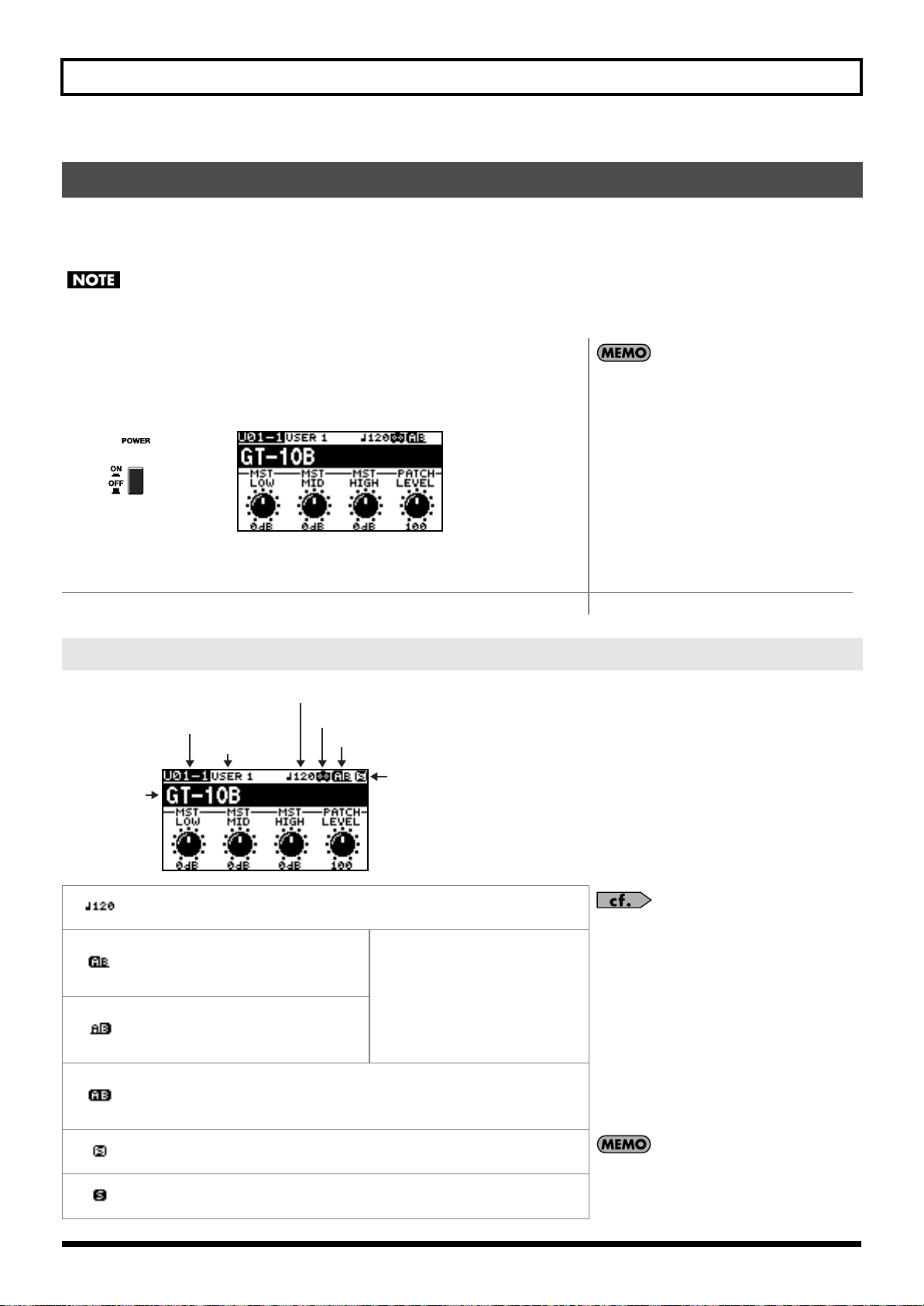
The Icons in the Play Screen
Master BPM
Bank - Patch Number
Category Name
Patch Name
Displays the Master BPM (p. 122) value for each patch.
When the Effect Ch.Mode is set to
Single, effect channel A is selected.
Also, this is displayed when the Effect Ch.Mode is set to Dynamic B.
When the Effect Ch.Mode is set to
Single, effect channel B is selected.
Also, this is displayed when the Effect Ch.Mode is set to Dynamic A.
This is displayed when the Effect Ch.Mode is set to Dual Mix, Dual L/R, or
Freq Divide.
When the Effect Ch.Mode is set to Dynamic A or Dynamic B, it is displayed
according to the input level.
OUTPUT SELECT setting
Effect Channel
PREAMP Solo Sw
For details on the OUTPUT SELECT icons, refer to
“Making Settings for a Connected Device (Output
Select)” (p. 26).
When the Effect Ch.Mode is set to
Dynamic, the display switches between A and B according to the input
level.
24
This is displayed when the PREAMP Solo Sw is Off.
This is displayed when the PREAMP Solo Sw is On.
The “S” icon is not shown if the selected amp type
doesn’t have the Solo Sw parameter.
Page 25

Chapter 1 Outputting Sounds
* About the S icon and A icon displayed at the Screen 4 and 5.
The S icon displays when the Pedal Function is enabled (p. 48).
The A icon displays when the Patch Assign Function is enabled (p. 51).
Switching the Play Screen
The GT-10B has a variety of Play screen variations. You can switch the information shown in the Play screen by pressing .
• You can use the PARAMETER knobs 1 through 4 to work with the values of the parameters displayed at the bottom of the Play screen. Also, for each parameter,
you can change the corresponding assignment at the SYS KNOB ASSIGN screen (p. 47).
• The parameter name displayed at the each Play screen is abbreviated. For details about parameter names, refer to “Parameters You Can Set with PDL:CTL/EXP”
(p. 125) or “Display of Parameters You Can Set with SYS KNOB SETTING” (p. 138).
Chapter
1
Screen 1
This displays the name of the patch and the
parameters you can work with using the
PARAMETER 1 through 4 controls.
Screen 4
This screen displays the functions assigned
to CTL 1 and 2, the EXP PEDAL SW, and the
EXP Pedal.
Screen 2
This screen displays the effect channel level
and the preamp that’s in use.
Screen 5
This screen displays the functions assigned to
the Number Pedal Switch, CTL 3 and 4, the
external expression pedal (EXP PEDAL2).
Screen 3
This screen displays the effect channel
mode and the effect channel level.
Screen 6
This is the screen shown when you’re in
Manual mode (p. 56). Manual mode is enabled only while this screen is displayed.
Pressing [CATEGORY/ENTER] in this
screen allows you to make settings for
MANUAL MODE SETTING.
Screen 7
The effects used, as well as their connection
sequence (CHAIN) in a channel is indicated.
Adjusting the Output Level
1.
Adjust the GT-10B’s output level with the OUTPUT LEVEL knob.
Screen 8
The patch name and the output level meter
are displayed.
25
Page 26
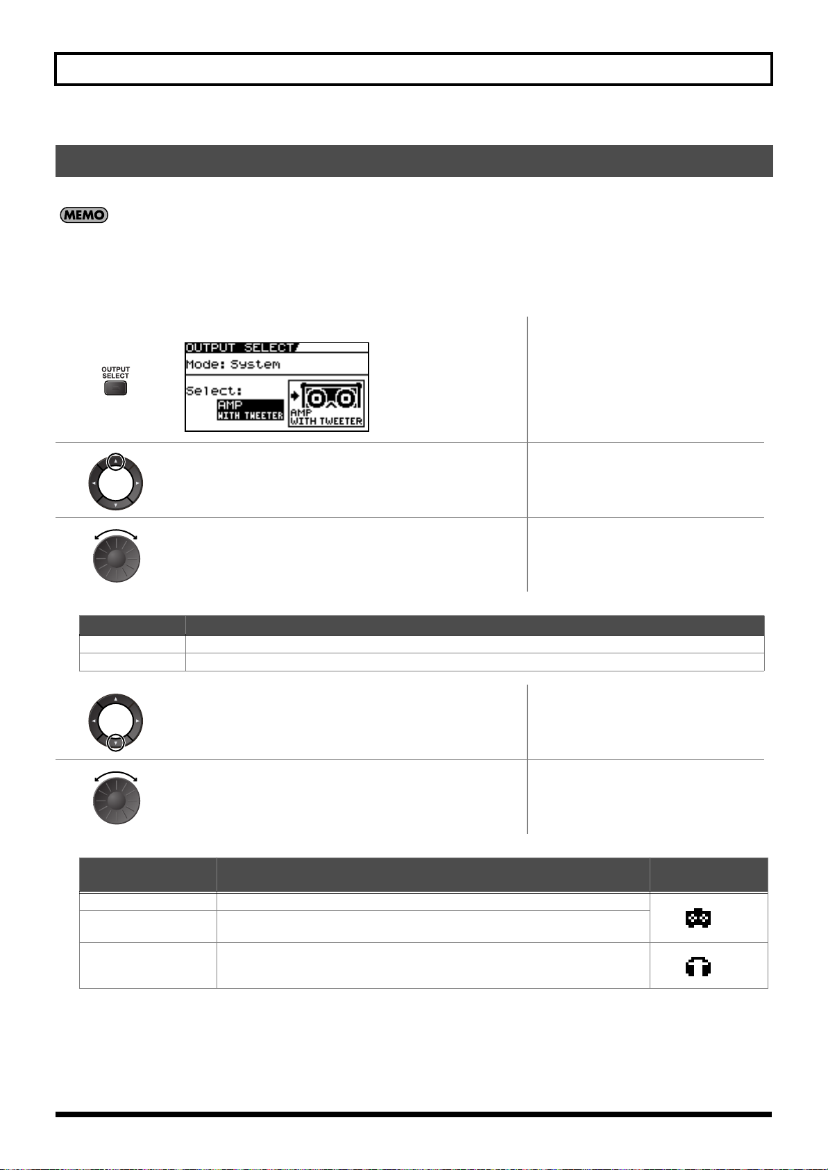
Chapter 1 Outputting Sounds
Making Settings for a Connected Device (Output Select)
Select the type of device connected to the OUTPUT jack.
• To derive the maximum performance from the GT-10B, be sure to make the correct setting for OUTPUT SELECT, the one that’s most suitable for your setup.
• The OUTPUT SELECT function affects sounds from the OUTPUT jacks. The output from the SUB OUTPUT jacks will always be equivalent to the sound that is
output when the LINE/PHONES setting is used.
• If the headphones are connected to the PHONES jack, the output from OUTPUT jack and PHONES jack will be equivalent to the sound that is output when the
LINE/PHONES setting is used.
The OUTPUT SELECT screen appears.
1.
2.
3.
Value
Patch
System This uses the system’s Output Select setting. The same output setting is used for all patches.
4.
5.
Value
AMP WITH TWEETER
AMP NO TWEETER
Move the cursor to Mode.
Set the Mode.
Explanation
This uses the patch’s Output Select setting. You can use a different output setting for each individual patch.
Move the cursor to Select.
Choose the operation for the Select parameter.
Explanation Icon displayed on
Use this setting when connecting to a tweeter-equipped bass amp.
Use this setting when connecting to a bass amp that has no tweeter. The high-frequency range is adjusted.
the Play screen
26
LINE/PHONES
Use this setting when connecting to a multi-track recorder for recording or when using headphones.
Page 27

Chapter 1 Outputting Sounds
Turning Off the Power
Before turning off the power, confirm the following.
• Is the volume on the GT-10B, your amp, and all other connected devices turned down to the minimum level?
• Have you saved any patches containing settings that have been changed? (p. 43)
1.
Turn off the power to the bass amp (power amp) → any external effects
processors and other devices.
Chapter
1
2.
Turn the GT-10B’s power off.
Changes in patch settings are lost when the power
is turned off. If you want to save changes in the
settings, carry out the Write procedure (p. 43)
before turning off the power.
Tuning the Bass (TUNER)
When the Tuner is turned on, sounds input to the GT-10B are output directly as is (bypassed), and the tuner is activated.
Under these conditions you can then tune your bass.
Turning the Tuner Function On and Off
1.
About the Display During Tuning
With the GT-10B’s internal tuner, the Note Name and the Tuning Guide are shown of the display, indicating the difference
between the input sound and the sound in the display.
The tuner is switched on or off.
Note Name
Tuning Guide
When the difference from the correct pitch falls within 50 cents, the Tuning Guide then indicates the size of that difference. As you
watch the Tuning Guide, tuning until the center indicator lights up.
fig.07-090
Too High
Tuned
Too Low
27
Page 28
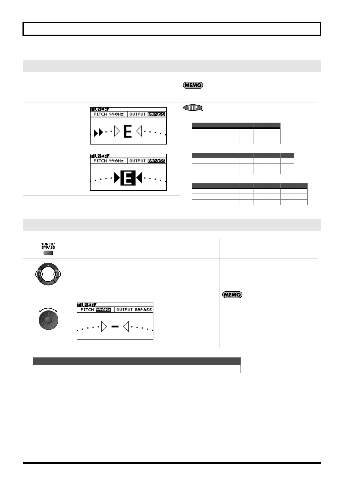
Chapter 1 Outputting Sounds
• General Four-String Bass
• General Five-String Bass
• General Six-String Bass
4th 3rd 2nd 1st
Regular E A D G
1/2 Step Down
DGC
F
1 Step Down D G C F
5th 4th 3rd 2nd 1st
Regular B E A D G
1/2 Step Down
ADGCF
1 Step Down A D G C F
6th 5th 4th 3rd 2nd 1st
Regular B E A D G C
1/2 Step Down
ADGCF
B
1 Step Down A D G C F
A
How to Tune
1.
Play a single open
note on the string
being tuned.
2.
Tune the string until
the string name
appears in the
display.
3.
Keep checking the
Tuning Guide, tuning
until the center
indicator lights up.
The Note Name closest to the pitch of the
string that was played appears in the
display.
Only play a single note on the one string being tuned.
4.
Repeat Steps 1–3 until all of the strings are tuned.
Changing the Tuner Settings (Tuner Pitch)
1.
2.
3.
Range
435Hz–445Hz
Turn on the Tuner.
Move the cursor to PITCH.
Change the reference pitch.
Explanation
This sets the reference pitch.
• The frequency of A4 (the middle A on a piano
keyboard) played by an instrument (such as a
piano) that provides the pitch to which the
other instruments refer in tuning before a
performance begins is called the reference
pitch.
• This is set to 440 Hz when shipped from the
factory.
28
Page 29
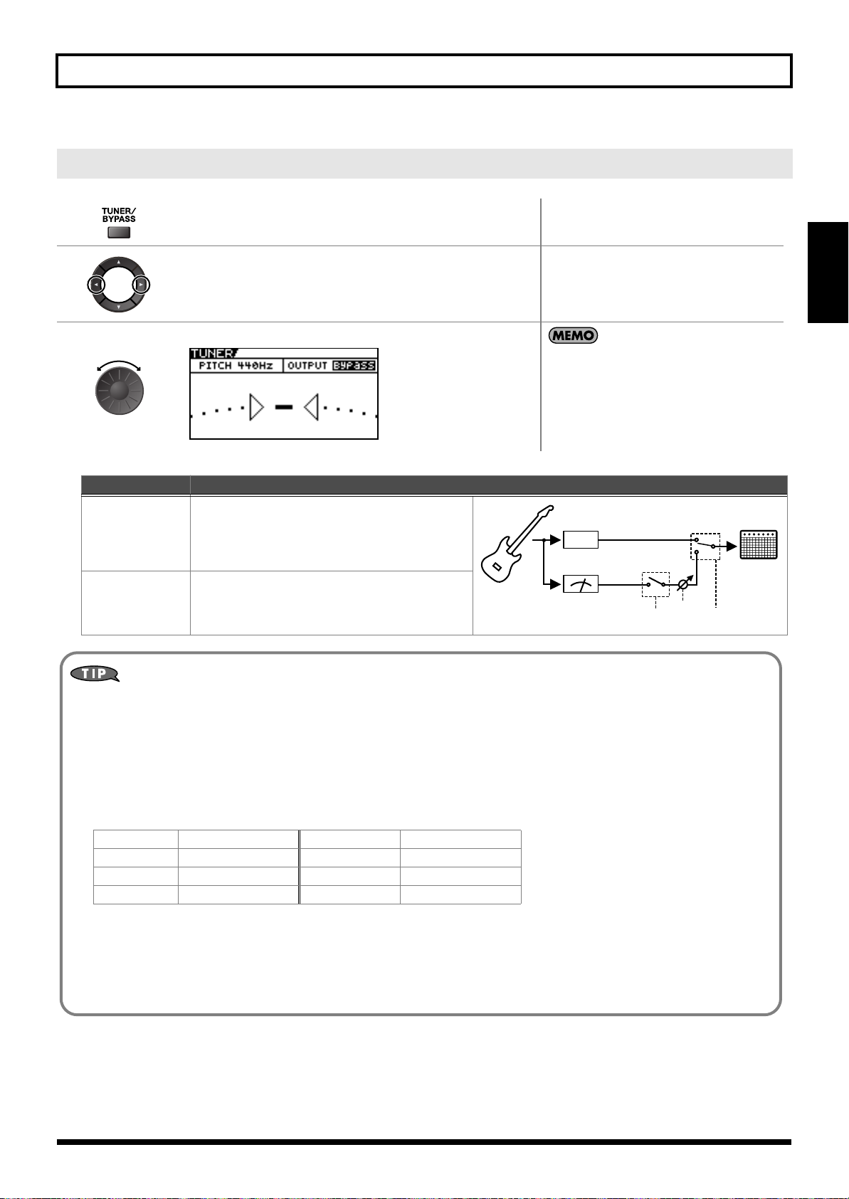
Changing the Tuner Settings (Tuner Out)
TUNER
Effector
FX
Off
On
TUNER
Switch
TUNER
OUTPUT
EXP
Pedal
Mute
Bypass
Chapter 1 Outputting Sounds
1.
2.
Turn on the Tuner.
Move the cursor to OUTPUT.
Select the output while Tuner is on.
3.
Value
Bypass
Mute Sounds are muted, and no sound is output.
Explanation
Sounds input to the GT-10B bypass the processing
and are output directly as is.
Chapter
1
• When OUTPUT is set to “Bypass,” and Tuner
is set to ON, you can adjust the volume of the
direct sound by operating the EXP Pedal.
• OUTPUT is set to “Bypass” when shipped
from the factory.
Switching the Tuner On and Off with the CTL Pedal
By setting the CTL Pedal function (p. 48) to “Tuner,” you can switch the tuner on and off with one of the CTL pedals.
Switching the Tuner On and Off by Lifting Up on the EXP Pedal
When the EXP Pedal is functioning as a Foot Volume control, set one of the ASSIGN 1–8 Assign Variable settings (p. 51) as
follows.
With these setting, you can switch on the Tuner by drawing back the EXP Pedal.
Target: Tuner Sw Src Mode: Moment
Min: On ActRngLo: 0
Max: Off ActRngHi: 1
Source: EXP1 PEDAL
Switching the Tuner On and Off with the Number Pedal
Set the Num Pdl Sw function (p. 58) to Tuner to switch the tuner on and off with the number pedal of the current patch.
29
Page 30
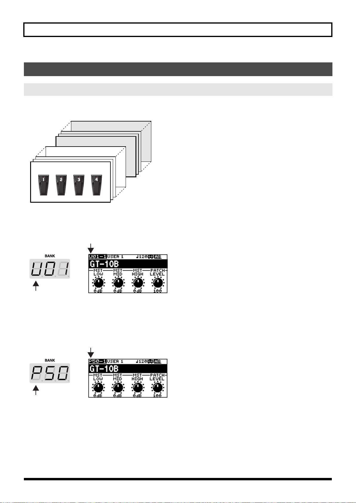
Chapter 1 Outputting Sounds
Selecting a Tone (Patch Change)
What is a Patch?
A combination (or set) of effects together with a group of parameter settings is called a “patch.”
The GT-10B can store 400 different patches in memory, organized by bank and number as shown below.
fig.02-010
Preset Bank 50
Preset Bank 01
User Bank 50
User Bank 01
User Banks (U01–U50)
Newly created effects settings are saved in the User banks. Patches in these banks are called “User patches.”
A “U” appears in the display when a User patch is selected.
fig.02-020d
Preset Banks (P01–P50)
The Preset banks contain effect settings that make full use of the features the GT-10B has to offer. The patches in these banks are
called “Preset patches.” When you change the settings of a Preset patch, save the result as a User patch. Preset patches cannot be
overwritten.
A “P” appears in the display when a Preset patch is selected.
fig.02-030d
30
Page 31

Chapter 1 Outputting Sounds
Using the Pedal to Select the Patch
Patches are switched by selecting a “bank” (U01–U50, P01–P50) and “number” (1-4). The bank and number appear in the GT10B’s display as shown in the following figure.
fig.02-040d
Number
Bank
Bank
fig.02-050
Number
Chapter
1
• When selecting a patch, even if a new bank is selected, the patch is not switched until you also choose the number. If you want to be able to switch patches
merely by selecting a different bank, adjust the Bank Change mode (p. 76) setting.
• You can also set the unit so certain effects continue to be used with a following patch after you switch patches. For details, refer to “Keeping Effect Sounds
Playing After Patches Are Switched (Patch Change Mode)” (p. 72).
Choosing a Patch in the Same Bank
• The indicator for the selected number pedal
1.
Choose the number of the patch you want to use.
lights up.
• On the GT-10B, you cannot switch patches in
any screen other than the Play screen. Press
[EXIT] to return to the Play screen (p. 25).
Choosing a Patch in a Different Bank
1.
2.
Select the bank.
Choose the number of the patch you want to use.
Press the BANK pedals to select the desired bank.
After bank selection, the GT-10B stands by for
specification of the patch number, and the number
pedal indicators light up.
• The indicator for the selected number pedal
lights up.
• On the GT-10B, you cannot switch patches in
any screen other than the Play screen. Press
[EXIT] to return to the Play screen (p. 25).
31
Page 32

Chapter 1 Outputting Sounds
Using the Dial to Select the Patch
1.
Select the Patch.
On the GT-10B, you cannot switch patches in any
screen other than the Play screen. Press [EXIT] to
return to the Play screen (p. 25).
Separating Patches into Groups (CATEGORY)
The GT-10B includes a function that allows you to categorize patches into a number of different groups. This is called the
CATEGORY function (p. 40). Specifying the category for each patch makes searching for patches more convenient.
The CATG screen appears.
1.
2.
The categories and the patches in these categories are shown in list
format.
Select the category.
• On the GT-10B, you cannot enter the CATG
screen in any screen other than the Play screen.
Press [EXIT] to return to the Play screen (p. 25).
• You can also display the CATG screen from
PATCH SEARCH in the SYSTEM screen.
3.
The GT-10B switches to the selected patch.
Adjusting a Tone
On the GT-10B, the master equalizer parameters are assigned to the PARAMETER knobs of the Play screen by default.
You can use these PARAMETER knobs to adjust the sound quality globally, for all patches.
1.
2.
Select the Patch.
P1 knob: Adjust the low frequency range tone.
P2 knob: Adjust the middle frequency range tone.
P3 knob: Adjust the high frequency range tone.
32
Page 33

Chapter 2 Creating Sounds (Patch Edit)
Adjusts the volume level of the Ch.A compressor.
Adjusts the volume level of the Ch.A chorus.
Adjusts the volume level of the Ch.B reverb.
Adjusts the distortion (DRIVE) of the Ch.B.
Creating Sounds with Ease (EZ TONE)
Creating a Tone for the Song You Envision (Create)
If you already have a clear idea about the kind of sound you want to create, you can save yourself a lot of trouble by starting out
with a patch that is relatively similar to what you have in mind, then tweak its settings until you arrive at what you want.
EZ TONE CREATE lets you create sounds easily by choosing settings close to the musical genre and the feel of the song you want
to compose.
The current settings for the patch you are using at the moment are lost when you press EZ TONE [CREATE]. If you want to save the current settings, carry out the
Write procedure (p. 43) before performing the procedure below.
The TONE screen for EZ TONE CREATE appears.
1.
2.
3.
4.
P1, P2 knob: This selects the basic tone.
P3, P4 knob: This selects a variation.
The DRIVE Tone Grid for EZ TONE CREATE appears.
P1, P2 knob: This adjusts the distortion and the
compression effect.
P3, P4 knob: This adjusts the tone.
Switching patches causes all settings that have been made to be lost.
To save the sound you’ve created, carry out a Write operation (p. 43).
You can take parameters you’ve adjusted with EZ TONE CREATE and
fine-tune them further using EZ TONE EDIT or parameter operations. For
more information, refer to “Adjusting the Tone (Edit)” (p. 33).
Chapter
2
Adjusting the Tone (Edit)
By using EZ TONE EDIT you can adjust the sound of a patch with ease, without having to manipulate complicated parameters.
The EZ TONE EDIT screen appears.
1.
P1 knob: Adjusts the volume level of the compressor.
2.
P2 knob: Adjusts the distortion (DRIVE).
P3 knob: Adjusts the volume level of the chorus.
P4 knob: Adjusts the volume level of the reverb.
33
Page 34

Chapter 2 Creating Sounds (Patch Edit)
Setting the Effects
Turning an Effect On and Off
The GT-10B’s internal effects are switched on and off with button controls. When an effect is switched on, the button’s indicator
lights up; the indicator goes out when the effect is off.
[MASTER/PEDAL FX] does not light up.
The setting screen for the effects appears.
• With [FX-1] and [FX-2], the settings for the
currently selected effect are shown.
1.
• Pressing [MASTER/PEDAL FX] displays the
MST/PDL FX screen.
2.
3.
To select another effect to be switched on and off, repeat Steps 1 and 2.
(Press the button you pressed in step 1 a second time.)
The effect is switched on or off.
• If you want to name the patch or edit the name,
proceed to “Naming a Patch (PATCH NAME)”
(p. 42) before you save.
• If you want to save a tone with the settings
you’ve made, proceed as described in “Saving
a Patch (PATCH WRITE)” (p. 43).
On/Off Operations Using the PARAMETER Knobs
You can use the P1 through P4 knobs to switch on or off the effects whose icons are displayed in the PATCH EDIT screen or
MST/PDL FX screen.
PATCH EDIT screen
Select the
icon in the SYSTEM MENU screen.
MST/PDL FX screen
Press in the MST/PDL FX screen until the screen below appears.
34
Page 35

Chapter 2 Creating Sounds (Patch Edit)
Setting the Effects Simply (Quick Setting)
Each effect includes prepared sample settings called “Quick Settings.”
You can easily create new effect sounds just by selecting and combining these Quick Settings.
1.
2.
The setting screen for the effects appears.
Select the Quick Setting you want.
U**: User Quick Setting
P**: Preset Quick Setting
U01-1 – U50-4: User Patch Setting
P01-1 – P50-4: Preset Patch Setting
For the various FX-1 or FX-2 effects, or the ASSIGN 1 through 8 Quick
Settings, you can call up the respective settings described below.
• Each effect of the FX-1 or FX-2 (You can call up settings separately for FX1
and FX2.)
U01-1.1 – U50-4.2: User Patch Setting
P01-1.1 – P50-4.2: Preset Patch Setting
• ASSIGN (You can call up settings separately for ASSIGN 1 through 8)
U01-1.1 – U50-4.8: User Patch Setting
P01-1.1 – P50-4.8: Preset Patch Setting
• With FX-1 and FX-2, the settings for the
currently selected effect are shown.
• Pressing [MASTER/PEDAL FX] displays the
MST/PDL FX screen.
• “---: User Setting” indicates that the effect
indicated in the display is set to be saved to the
currently selected patch, or that the settings are
currently being modified.
• When FX-1 or FX-2 has been selected in Step 1,
the settings for the effect selected by means of
the FX1/FX2 Select parameter (p. 105) are
switched.
• If you want to name the patch or edit the name,
proceed to “Naming a Patch (PATCH NAME)”
(p. 42) before you save.
• If you want to save a tone with the settings
you’ve made, proceed as described in “Saving
a Patch (PATCH WRITE)” (p. 43).
Chapter
2
Switching Between Knob View and List View
You can switch the setting screen for effects between a knob-format view and a list-format view.
1.
2.
The setting screen for the effects appears.
Each press switches between Knob View and List View.
Only the major parameters are shown in Knob View, you can adjust
the parameters quickly. If you want to have all parameters appear,
switch to List View.
With [FX-1] and [FX-2], the settings for the
currently selected effect are shown.
35
Page 36

Chapter 2 Creating Sounds (Patch Edit)
Operations Using the PARAMETER Knobs
In the effects screens, the knobs correspond to the displayed parameters.
Adjusting the Parameters
Each effect comprises several different kinds of parameters. You can more precisely create the sounds you want by editing each of
these parameters individually.
The setting screen for the effects appears.
• With [FX-1] and [FX-2], the settings for the
currently selected effect are shown.
1.
2.
3.
To adjust another effect parameter, repeat Steps 1 and 2.
Make the settings for the parameters.
• Pressing [MASTER/PEDAL FX] displays the
MST/PDL FX screen.
Some effects include multiple pages for the
parameter settings. You can use [ ] and
[ ] to switch the pages.
• If you want to name the patch or edit the name,
proceed to “Naming a Patch (PATCH NAME)”
(p. 42) before you save.
• If you want to save a tone with the settings
you’ve made, proceed as described in “Saving
a Patch (PATCH WRITE)” (p. 43).
36
Page 37

Chapter 2 Creating Sounds (Patch Edit)
Adjusting EQ (Equalizer)
In the EQ screen, using [DISPLAY MODE] to switch the
screen lets you check the current status of the settings by
means of a graph.
[ ] and [ ] to switch pages, and use the P1
Use
through P4 knobs to adjust the respective parameters.
You can use the same technique to adjust the various parameters
under PARA EQ for FX-1 and FX-2 as well.
For details, refer to “EQ (Equalizer)” (p. 105).
Adjusting GRAPHIC EQ for FX-1/2
In the GRAPHIC EQ screen for FX-1 or FX-2, using
[DISPLAY MODE] to switch the screen lets you check
the current status of the settings by means of a slider
view.
[ ] and [ ] to select the range you want to adjust,
Use
and use the P1 through P4 knobs to adjust the respective
parameters.
For details, refer to “GRAPHIC EQ (Graphic Equalizer)” (p. 108).
Chapter
2
Changing the Connection Order of Effects (Effect Chain)
Here’s how you can change the order in which the effects are connected.
The MST/PDL FX screen appears.
1.
Select FX CHAIN.
2.
The FX CHAIN screen appears.
The icon displayed on the FX CHAIN screen
indicates the status as described below.
3.
: Effect on
: Effect off
: Selected effect (movable)
37
Page 38

Chapter 2 Creating Sounds (Patch Edit)
Select an effect you want to move.
Pressing the effect button for the effect you want to move lets you choose the
effect.
4.
Compressor/
Limiter
OD/DS Chorus Send/Return
PREAMP Reverb
EQ Pedal FX INPUT jack
FX-1
FX-2
Delay Foot Volume
Noise
Suppressor1
Noise
Suppressor2
• Pressing [CATEGORY/ENTER] or the
EFFECTS SELECT button for the currently
selected effect switches the effect on or off.
• There are two effect routes—channel A (upper)
and channel B (lower)—and [CHANNEL
SELECT] is used to select which one to use.
Digital/USB
Out
OUTPUT jack
5.
6.
If you want to change the sequence further, repeat Steps 4 and 5.
Move an effect to the point where you want to have an effect inserted.
Checking the Effect Level with the Level Meter
In the upper right of the FX CHAIN screen, you can meter the output level of each effect.
To check an effect’s output level, move the cursor to the desired effect.
You can check the level of signals being input to the INPUT jack by selecting .
Selecting allows you to check the level of signals output from the GT-10B.
and cannot be moved.
• If you want to name the patch or edit the name,
proceed to “Naming a Patch (PATCH NAME)”
(p. 42) before you save.
• If you want to save a name of the patch with
the settings you’ve made, proceed to “Saving a
Patch (PATCH WRITE)” (p. 43).
38
Page 39

Chapter 2 Creating Sounds (Patch Edit)
Using Two Different Type Effects (Channel Select)
GT-10B’s effector has two routes (EFFECT CHANNEL). You can use it by switching or mixing each route for application as
needed.
The MST/PDL FX screen appears.
1.
Select CH. SELECT.
2.
Chapter
2
3.
4.
Value
Single
Dual
Mix
Dual
L/R
Freq
Divide
The CH. SELECT screen appears.
Select the Ch.Mode.
Explanation Value Explanation
Only the channel se-
A
B
A
B
Low-frequency
Range
A
B
High-frequency
Range
A
B
lected with Ch.Select or [CHANNEL
SELECT] is used.
The output of Channels A and B is
mixed.
Channel A is output
from the left and
L
Channel B is output
R
from the right.
The low-frequency
range is assigned to
Channel A, and the
high-frequency
range is assigned to
Channel B.
Dynamic
SW
Dynamic A
Dynamic B
Input Level
Channel A’s volume level is controlled. The volume in
Channel B is fixed.
Channel B’s volume level is controlled. The volume in
Channel A is fixed.
• Pressing [DISPLAY MODE] toggles the display
between Knob View and List View.
For information on the parameters, refer to
“CH.SELECT (Channel Select)” (p. 133).
• When you want to change the effect channel,
press [CHANNEL SELECT].
You can also select the Ch.Mode using P2 knob.
A
B
Detect
Channels A and B are
switched according to the
bass input volume level.
This produces dynamic tonal changes in response to the
picking dynamics.
39
Page 40

Chapter 2 Creating Sounds (Patch Edit)
Grouping Patches by Category (CATEGORY)
You can assign categories to patches and group them accordingly.
1.
2.
3.
4.
5.
Select the patch you want to include in a category.
The MST/PDL FX screen appears.
Select NAME.
The PATCH NAME screen appears.
Select a category.
• If you want to name the patch or edit the name,
proceed to “Naming a Patch (PATCH NAME)”
(p. 42) before you save.
• If you want to save a name of the patch with
the settings you’ve made, proceed to “Saving a
Patch (PATCH WRITE)” (p. 43).
40
Page 41

Chapter 2 Creating Sounds (Patch Edit)
Naming User Categories (CATEGORY NAME)
The CATEGORY function also features ten user categories (USER1–10) you can name however you like.
The SYSTEM MENU screen appears.
SYSTEM
1.
Select CATEGORY NAME.
2.
Chapter
2
The CATEGORY NAME screen appears.
3.
4.
5.
Use the same procedure as in “Naming a Patch (PATCH NAME)” (p. 42) to edit the name
of the category.
6.
twice.
Select the name of the category you want to edit.
The Play screen appears.
Category names are system parameters. They are
saved at the time they are entered, and don’t
require the Write procedure.
41
Page 42

Chapter 2 Creating Sounds (Patch Edit)
Naming a Patch (PATCH NAME)
Each patch can be given a name (PATCH NAME) consisting of up to sixteen characters. You’ll probably want to take advantage of
this feature by assigning names that suggest the sound you’ll obtain, or the song in which it’ll be used.
1.
2.
3.
4.
Select the patch whose name you want to edit.
The MST/PDL FX screen appears.
Select NAME.
The PATCH NAME screen appears.
Move the cursor to the position at which you want to change a char-
5.
6.
acter.
Select the character.
You can use the following convenient operations.
Operation
7.
If you want to edit names further, repeat Steps 5 and 6.
Description Operation Description
Inserts a blank space at the cursor position.
Inserts a keyword associated with the
patch at the cursor position.
Switches between uppercase and lowercase letters.
Deletes the character and shifts the characters that follow to the left.
Switches between letters, numerals, and
symbols.
Sets the category for the current patch.
Refer to “Grouping Patches by Category
(CATEGORY)” (p. 40)
If you want to save a name of the patch with the
settings you’ve made, proceed to “Saving a Patch
(PATCH WRITE)” (p. 43).
42
Page 43

Chapter 3 Saving a Tone
Saving a Patch (PATCH WRITE)
If you want to save the changes in the settings, carry out the Write procedure.
The patch previously stored at the write destination will be lost once the write is executed.
1.
The PATCH WRITE screen appears.
Select the write-destination User patch.
2.
3.
The GT-10B saves the changes in the settings to the write-destination
patch.
Copying Patches (PATCH COPY)
You can copy a Preset or User patch to another User patch.
The patch previously stored at the write destination will be lost once the write is executed.
1.
Select the patch you wish to copy.
When no edits have been made to the currently
selected patch, the PATCH COPY screen is
displayed.
To cancel the Write procedure, press [EXIT]. The
Play screen returns to the display.
You can also use the procedure described in
“Using the Pedal to Select the Patch” (p. 31) to
select the write-destination.
If you want to name the patch or edit the name,
proceed to “Naming a Patch (PATCH NAME)” (p.
42) before you save.
“Selecting a Tone (Patch Change)” (p. 30)
Chapter
3
2.
3.
4.
The PATCH COPY screen appears.
Select the copy-destination User patch.
The GT-10B copies the patch selected in Step 1 to the copy-destination
patch.
When edits have been made to the currently
selected patch, the PATCH WRITE screen is
displayed.
To cancel the Copy procedure, press [EXIT]. The
Play screen returns to the display.
You can also use the procedure described in
“Using the Pedal to Select the Patch” (p. 31) to
select the copy destination.
43
Page 44

Chapter 3 Saving a Tone
Exchanging Patches (PATCH EXCHANGE)
On the GT-10B, you can “swap” or exchange the positions of two User patches. The following explains how this is done.
1.
2.
3.
4.
5.
Select the exchange source patch.
The PATCH COPY screen appears.
Select the PATCH EXCHANGE (page 2) screen.
Select the exchange destination User patch.
The GT-10B exchange the positions of the two User patches.
“Selecting a Tone (Patch Change)” (p. 30)
When edits have been made to the currently
selected patch, the PATCH WRITE screen is
displayed.
To cancel the Exchange procedure, press [EXIT].
The Play screen returns to the display.
You can also use the procedure described in
“Using the Pedal to Select the Patch” (p. 31) to
select the exchange destination.
Initializing Patches (PATCH INITIALIZE)
You can return (initialize) a User patch to its original factory settings. This is convenient when you want to create a new patch
from scratch.
Any tone settings you’ve stored in a patch are lost once the initialization is executed.
1.
2.
3.
The PATCH COPY screen appears.
Select the PATCH INITIALIZE (page 3) screen.
Select the User patch you want to initialize.
When edits have been made to the currently
selected patch, the PATCH WRITE screen is
displayed.
To cancel the Initialize procedure, press [EXIT].
The Play screen returns to the display.
You can also use the procedure described in
“Using the Pedal to Select the Patch” (p. 31) to
select the initialize destination.
4.
44
The selected patch is initialized.
Page 45

Chapter 3 Saving a Tone
Storing Settings by Effect (User Quick Settings)
In addition to storing settings in the form of patches, you can also store settings for individual effects.
Since you can use such stored settings in other patches, just like with the Preset Quick Settings (p. 35), storing effects settings you
like ahead of time User Quick Settings is a convenient way to create new patches.
Effects That Can Be Stored
• COMP
• OD/DS
• PREAMP
•EQ
• FX-1/FX-2 Effects
• DELAY
• CHORUS
• REVERB
• PEDAL FX WAH and Pedal Bend
• SEND/RETURN
• ASSIGN1–8
1.
2.
3.
4.
The PATCH COPY screen appears.
The QUICK FX WRITE screen appears.
Select the effect settings you want to save.
3-020d
The screen for specifying the destination to which to save the settings
appears.
Move the cursor to “Write to.”
Select the save-destination for the settings.
When edits have been made to the currently
selected patch, the PATCH WRITE screen is
displayed.
• To save ASSIGN 1-8 settings (p. 51), set the
SOURCE parameter to ASSIGN 1-8.
• For FX-1/FX-2, the settings in the currently
chosen effects set by FX select (p. 105) will be
saved.
• The effects shown below change with each
press of [MASTER/PEDAL FX].
- PEDAL WAH
- PEDAL BEND
- SEND/RETURN
- ASSIGN 1–8
When you want to change the User Quick Setting
name (12 characters), press [DISPLAY MODE]. For
information on how to enter characters, refer to
steps 4 through 6 of “Naming a Patch (PATCH
NAME)” (p. 42).
Chapter
3
5.
The settings are saved.
45
Page 46

Chapter 3 Saving a Tone
Swapping Effect Settings Between Channels
You can swap the settings for the two effect channels.
1.
2.
3.
The PATCH COPY screen appears.
The CH A/B UTILITY screen appears.
3-020d
This swaps the arrangement of channel A and channel B in the FX
CHAIN.
When edits have been made to the currently
selected patch, the PATCH WRITE screen is
displayed.
46
Page 47

Chapter 4 Playing Sounds
Setting the Functions of the Knobs of the Play Screen
You can change the functions of the PARAMETER knobs.
1.
2.
3.
4.
5.
SYSTEM
The SYSTEM MENU screen appears.
Select CONTROL.
The CONTROLLER screen appears.
Select the SYS KNOB SETTING screen (page 1).
Select the parameter knob (Knob P1–P4) whose assignment
you want to change.
Chapter
4
6.
7.
To change another controller setting, repeat Steps 5–6.
8.
twice.
Change the parameter settings.
The Play screen appears.
For information on what settings you can assign,
refer to “SYS KNOB SETTING (System Knob
Setting)” (p. 137).
CONTROLLER parameters are system
parameters. They are saved at the time they are
entered, and do not require a Write procedure.
47
Page 48

Chapter 4 Playing Sounds
Using Pedals to Control the Parameters
Using the CTL/EXP Pedal With the Same Functions Assigned at All Times (Pedal Function)
This applies the functions of the CTL pedal, EXP Pedal and EXP PEDAL SW globally to the GT-10B.
1.
2.
3.
4.
SYSTEM
The SYSTEM MENU screen appears.
Select CONTROL.
The CONTROLLER screen appears.
Select the controller whose assignment you want to change.
5.
6.
7.
8.
9.
To change another controller setting, repeat Steps 4–6.
10.
twice.
Select Prefernc.
Set the Prefernc parameter to System.
Select the parameter of the chosen controller whose settings
you want to change.
Change the parameter settings.
The Play screen appears.
48
For information on what settings you can assign,
refer to “Function” (p. 138).
CONTROLLER parameters are system
parameters. They are saved at the time they are
entered, and do not require a Write procedure.
Page 49

Chapter 4 Playing Sounds
Parameter Functions Switched
Foot Volume
Normal Foot Volume
(Does not include an ON/OFF
switching function)
Pedal Bend Pedal Bend On/Off
WAH Wah On/Off
PB/FV Pedal Bend, Foot Volume
WAH/FV Wah, Foot Volume
Example of Setting the Pedal Function
Setting the parameters as shown below in the EXP1 PEDAL SETTING screen enables you to constantly use the GT-10B’s
EXP Pedal as a wah pedal.
Prefernc: System
Function: WAH
Min: 0
Max: 100
Setting CTL/EXP Functions Individually in Each Patch (PEDAL FX)
This procedure sets the functions for the GT-10B’s controllers (CTL/EXP Pedal, EXP PEDAL SW) for individual patches.
* Set the Prefernc parameter of the CTL/EXP Pedal and EXP PEDAL SW (p. 137) settings to “Patch.”
1.
2.
3.
The MST/PDL FX screen appears.
Select PEDAL/FX.
Chapter
4
The PDL:CTL/EXP screen appears.
Pressing [DISPLAY MODE] toggles the display between Knob View and
List View.
• Some EXP Pedal parameters use multiple pages for the parameter
settings. You can use [ ] or [ ] to switch pages.
• Each time [MASTER/PEDAL FX] is pressed, the EXP Pedal functions
alternate as shown below.
4.
P1: CTL1 Pedal
P2: CTL2 Pedal
P3: EXP PEDAL SW
P4: EXP Pedal
5.
To save the settings, use the Write procedure (p. 43).
Make the parameter settings.
The currently selected setting is the one highlighted at the
lower right of the display.
For information on what settings you can assign, refer to “SW&PDL
FUNCTION” (p. 122).
49
Page 50

Chapter 4 Playing Sounds
EXP Pedal Function Quick Settings
Selecting these prepared sample settings (Quick Settings) lets you choose optimal values for the related parameters
instantly. This allows you to complete the settings simply and easily without the need to set each parameter individually.
When SYSTEM or CONTROLLER Messages Are Displayed
These appear when the Prefernc parameter for the Controller whose settings you attempted to change (CONTROLLER
screen (p. 137)) is set to System.
This means that the settings in the PDL:CTL/EXP screen, which are the patch parameters, have no effect.
To enable the settings in the PDL:CTL/EXP screen, set the Prefernc parameter to Patch beforehand.
To dismiss this message, press [EXIT].
1. Follow the procedure in “Setting CTL/EXP Functions Individually in Each Patch (PEDAL FX)” (p. 49) step 1–3
to display the PDL:CTL/EXP screen.
2.
Select either WAH/FV, PB/FV, WAH, or PB.
3.
The PDL:WAH screen or the PDL:PEDAL BEND screen appears.
4.
Select the Quick Setting (P**, U**).
Display Explanation
Quick:U** User Quick Settings
Quick:P** Preset Quick Settings
U01-1–U50-4 User Patch
When you select a User patch or Preset patch, you can use the existing patch’s
assign settings just as they are.
P01-1–P50-4 Preset Patch
5. To save the settings, use the Write procedure (p. 43).
50
Page 51

Chapter 4 Playing Sounds
Setting Each Controller Functions to Individual Patches (Assign)
You can set the CTL/EXP Pedal, EXP PEDAL SW, and external controllers (footswitch and expression pedal) connected to the
rear panel’s EXP PEDAL 2/CTL 3,4 jacks for each individual patch.
You can save up to eight separate settings per patch (using Assign numbers 1 through 8) that determine what parameters are
controlled by which controllers.
* Set the Prefernc parameter of the CTL/EXP Pedal and EXP PEDAL SW (p. 137) settings to “Patch.”
Quick Settings
When you select prepared settings (Quick Settings), the relevant parameters are instantly set to their optimal values. This lets you
make the settings simply, instead of setting each individual parameter separately.
1.
2.
3.
4.
5.
The MST/PDL FX screen appears.
Select ASSIGN.
The ASSIGN screen appears.
Select one of the ASSIGN number (No.1–8).
Set the selected Assign number to “On.”
Chapter
4
Each time [MASTER/PEDAL FX] is pressed it
alternately switches the selected ASSIGN number
on and off. When on, the Assign number at the
bottom left of the display and the “ON” indication
at the bottom right are highlighted. Be sure to set
any Assign settings not being used to “Off.”
6.
Display
Quick:U**
Quick:P** Preset Quick Settings
U01-1.1–U50-4.8 User Patch
P01-1.1–P50-4.8 Preset Patch
7.
To use the Quick Settings with other Assigns, repeat Steps 4–8.
8.
To save the settings, use the Write procedure (p. 43).
Select the Quick Setting (P**, U**).
Explanation
User Quick Settings
When you select a User patch or Preset patch, you can use the existing patch’s assign
settings just as they are.
51
Page 52

Chapter 4 Playing Sounds
Manual Settings
Here, you can individually determine which controller is to control which parameter.
1.
2.
3.
4.
5.
The MST/PDL FX screen appears.
Select ASSIGN.
The ASSIGN screen appears.
Select one of the ASSIGN number (No.1–8).
Set the selected Assign number to “On.”
Only the TARGET and the SOURCE are shown in
Icon View. If you want to have all parameters
appear, switch to List View.
For information on the parameters, refer to
“ASSIGN 1–8” (p. 126).
Each time [MASTER/PEDAL FX] is pressed it
alternately switches the selected ASSIGN number
on and off. When on, the Assign number at the
bottom left of the display and the “On” indication
at the bottom right are highlighted. Be sure to set
any Assign settings not being used to “Off.”
6.
7.
8.
To set the other Assigns, repeat Steps 4–7.
9.
To save the settings, use the Write procedure (p. 43).
Select the controller that you want to edit the parameter.
Select the parameter you wish to control.
You can rapidly select the parameter you want by
using the P1 knob to navigate down from the
broad category.
52
Page 53

Chapter 4 Playing Sounds
Parameters That Can Be Set in List View
The following describes the parameters that can be set when you switch to List View in the ASSIGN screen.
Pressing [DISPLAY MODE] toggles the display between Knob View and List View.
* The screen that’s shown uses ASSIGN No. 1 as an example.
Parameter
Target
Min This sets the minimum value for the target’s controllable range.
Max This sets the maximum value for the target’s controllable range.
Parameter
Source
Src Mode
ActRngLo This sets the minimum for the range in which the value of the setting can be changed.
ActRngHi This sets the maximum for the range in which the value of the setting can be changed.
For more information about each parameter, refer to “ASSIGN 1–8” (p. 126).
Explanation
Use to select the parameter you want to control.
Explanation
This selects the controller assigned to the function.
Moment
Toggle
The normal state is Off (minimum value), with the switch On (maximum
value) only while the footswitch is depressed.
The setting is toggled On (maximum value) or Off (minimum value) with
each press of the footswitch.
Chapter
4
53
Page 54

Chapter 4 Playing Sounds
About the Range of a Target’s Change
The value of the parameter selected as the target changes within the range defined by “Min” and “Max,” as set on the GT-10B.
When using an external footswitch, or other controller that acts as an on/off switch, “Min” is selected with Off (CLOSED),
and “Max” is selected with On (OPEN).
When using an external expression pedal or other controller that generates a consecutive change in the value, the value of
the setting changes accordingly, within the range set by the minimum and maximum values. Also, when the target is of an
on/off type, the median value of the received data is used as the dividing line in determining whether to switch it on or off.
When using the footswitch:
When using the EXP Pedal:
When controlling the On/Off target with the
EXP Pedal:
* The range that can be selected changes according to the target
setting.
* When the “minimum” is set to a higher value than the
“maximum,” the change in the parameter is reversed.
* The values of settings can change if the target is changed
after the “minimum” and “maximum” settings have been
made. If you’ve changed the target, be sure to recheck the
“minimum” and “maximum” settings.
0
127
Degree to
Which Expression
Pedal Is Depressed
EXP Pedal
When the pedal
is fully raised
When the pedal
is fully advanced
Min
Max
Allowable Parameter
Settings Range
Value
Max
Settings Range
Min
Allowable Parameter
Off On
Footswitch
Value
On
Off
0
When the pedal
is fully raised
When the pedal
is advanced halfway
EXP Pedal
Degree to
Which Expression
Pedal Is Depressed
127
When the pedal
is fully advanced
About the Range of a Controller’s Change
This sets the operational range within which the value of the setting changes when an EXP Pedal or other controller that
changes the value consecutively is used as the source. If the controller is moved outside the operational range, the value
does not change, it stops at “minimum” or “maximum.”
(Example) With ActRngLo: 40, ActRngHi: 80
Value
On
Off
When the pedal
is fully raised
0
ActRng
Lo
40 8060
Center
value
EXP Pedal
ActRng
Hi
127
When the pedal
is fully advanced
54
MAX
Settings Range
MIN
Allowable Parameter
When the pedal
0
is fully raised
40 80
ActRngLo
EXP Pedal
ActRngHi
When the pedal
is fully advanced
* When using a footswitch or other on/off switching controller as the source, leave these at “ActRngLo: 0” and “ActRngHi: 127.”
With certain settings, the value may not change.
Which Expression
Pedal Is Depressed
127
Degree to
Degree to
Which Expression
Pedal Is Depressed
Page 55

Chapter 4 Playing Sounds
Example of Assign Settings
Setting the parameters as shown below enables you to use the GT-10B’s EXP Pedal as a UNI-V Rate parameter.
Target: FX1:UV:Rate Src Mode: Moment
Min: 0 ActRngLo: 0
Max: 100 ActRngHi: 127
Source: EXP1 PEDAL
Activating the Virtual Expression Pedal at the Start of Operations (Internal Pedal System)
The GT-10B features a function called Internal Pedal system. This function assigns specified parameters to a virtual expression
pedal (the internal pedal), providing an effect that automatically changes volume and tone in real time just the way an expression
pedal functions.
The Internal Pedal system features the following three functions, allowing you to set Source for each ASSIGN No.1-8 of the
“Manual Settings” (p. 52).
* When the Internal Pedal or the Wave Pedal is used, set the ASSIGN Src Mode to Moment.
Chapter
Internal Pedal
With the trigger you have set, the assumed expression pedal starts working. If you have set INTERNAL PDL to Source, set the Int
Trig parameter.
For more detailed information on the parameters that can be set using Internal Pedal, refer to “Int Trig (Internal Pedal Trigger)” (p. 126), “Int Time (Internal Pedal
Time)” (p. 126), and “IntCurve (Internal Pedal Curve)” (p. 126).
Wave Pedal
This changes the parameter selected as a target in a certain cycle with the assumed expression pedal. When you have set Wave
Pedal for Source, the WaveRate and Waveform should be set.
For more detailed information on the parameters that can be set using Wave Pedal, refer to “WaveRate (Wave Pedal Rate)” (p. 126) and “Waveform (Wave Pedal
Form)” (p. 126).
Input Level
The parameter set as the target changes in response to the input level.
If you want to adjust the input sensitivity, set the “INPUT SENS” (p. 127).
4
55
Page 56

Chapter 4 Playing Sounds
Turning the Effects On and Off with the BANK/Number Pedals (Manual Mode)
The GT-10B features a Manual mode, in which the pedals are used for switching specified effects on and off.
In Manual mode, you can switch effects on and off without changing the patch number.
Switching to Manual Mode
Press this button several times until the following screen
appears.
1.
Manual mode is enabled when this screen is displayed.
• You can press [CATEGORY/ENTER] in this
screen to switch to the MANUAL SETTING
screen (p. 57).
• Setting the TARGET to Manual Mode Sw in
“Manual Settings” (p. 52) enables you to
switch Manual mode on and off.
• In Manual mode, simultaneously pressing
[BANK ] and [BANK ] does not switch
Phrase Loop on and off.
Switching away from the MANUAL MODE screen turns off
Manual mode.
2.
Switching Effects On and Off with the Pedals
1.
Perform “Switching to Manual Mode” (p. 56), to turn Manual mode on.
2.
etc.
The pedal switches the assigned effect on or off.
The assigned effect is switched on or off with each
press of the pedal. When the assigned effect is on,
the indicator at the top of the pedal lights up.
56
Page 57

Assigning an Effect On/Off Switch to a Pedal
Chapter 4 Playing Sounds
1.
2.
3.
4.
5.
SYSTEM
The SYSTEM MENU screen appears.
Select MANUAL SETTING.
The MANUAL SETTING screen appears.
Select the pedal whose assignment you want to change.
Select the effect switch you want to assign to the pedal.
You can also enter the MANUAL SETTING screen
from the Play screen (p. 56).
Chapter
4
6.
To change another pedal setting, repeat Steps 4–5.
Assignable Effect Switches
Display Explanation
Off The function is not assign to the pedals.
Ch.A/B Switches between effect channel A and B.
Comp Switches the COMP on and off.
OD/DS Switches the OD/DS on and off.
Preamp Switches the PREAMP/SPEAKER on and off.
EQ Switches the EQ on and off.
FX1 Switches FX-1 on and off.
FX2 Switches FX-2 on and off.
Delay Switches the DELAY on and off.
Chorus Switches the CHORUS on and off.
Reverb Switches the REVERB on and off.
PdlFX Switches the PEDAL FX on and off.
S/R Switches the SEND/RETURN on and off.
AmpCtl Switches the Amp Control on and off.
Tuner
Switches the TUNER on and off.
Display Explanation
PL Switches the PHRASE LOOP on and off.
PL R/P Records/plays back the phrase.
PL Clr Clears the phrase.
PL M/P Mutes playback of the phrase.
BPMTap Used for tap input of the Master BPM.
DlyTap Used for tap input of the delay time.
MIDI
MMCPly
Lev+10 Increases the patch volume level by 10 units.
Lev+20 Increases the patch volume level by 20 units.
Lev -10 Decreases the patch volume level by 10 units.
Lev -20 Decreases the patch volume level by 20 units.
NumInc
NumDec
BnkInc Switches to the next higher bank number.
BnkDec Switches to the next lower bank number.
Controls the Start/Stop of external MIDI devices (such
as sequencers).
Controls the Play/Stop of external MIDI devices (such
as hard disk recorders).
Switches to the next higher patch number in the same
bank as the currently selected patch.
Switches to the next lower patch number in the same
bank as the currently selected patch.
57
Page 58

Chapter 4 Playing Sounds
Switching Settings with the Number Pedals
The GT-10B includes a function that allows you to turn the tuner on and off, switch effect channels, and perform other tasks by
pressing the pedal with the same number as the currently selected patch.
You can switch the following functions in any condition other than the Manual Mode (p. 56).
1.
2.
3.
4.
5.
SYSTEM
The SYSTEM MENU screen appears.
Select PLAY OPTION.
The PLAY OPTION screen appears.
Select Num Pdl Sw.
Set the Num Pdl Sw Parameter.
Display
Off
Tuner Switches the tuner on and off.
Ch. A/B Switches between effect channels A and B.
Explanation
Not used.
58
Page 59

Chapter 4 Playing Sounds
Phrase Loop Play
What’s Phrase Loop?
In this mode, you can record up to 38 seconds of material (recorded in mono) and repeatedly play material as a “phrase loop.” As
the loop plays, you can overdub new material if desired.
You can record a phrase loop with effects, or you can add effects after a loop has been recorded. Adding effects after-the-fact lets
you create special effects with recorded performances. It’s also a great way to audition tones, as you can adjust effect parameters
in real time while a phrase plays back.
Recorded phrases are deleted when Phrase Loop is switched off or when the power is turned off.
Using the Phrase Loop
Recording a Phrase (REC)
PHRASE LOOP
• Simultaneously pressing these a second time
1.
The unit goes into recording standby (The REC/DUB indicator flashes).
Press [BANK▼] and
[BANK▲] at the same
time.
stops loop playback and switches Phrase Loop
off.
• You cannot carry out this procedure in Manual
mode.
Chapter
4
2.
3.
Recording starts. (The REC/DUB indicator lights up.)
Play the phrase you want to record.
Recording stops. (The REC/DUB indicator goes out.)
The recorded phrase is looped (played repeatedly). (The
PLAY indicator lights up.)
Overdubbing Sound onto a Phrase (DUB)
1.
Follow the procedure in “Recording a Phrase (REC)” (p. 59) to record a phrase,
then perform loop play. (The PLAY indicator lights up.)
Overdubbing starts. (The REC/DUB indicator lights up.)
2.
3.
Play the phrase you want to overdub along with the playback
of the loop.
Overdubbing stops. (The REC/DUB indicator goes out.)
The phrase you just recorded is combined with the phrase
you recorded first and that sound is automatically played in a
loop. (The PLAY indicator lights up.)
The maximum recording time for monaural
recording is approximately 38 seconds. When the
recording time reaches 38 seconds, playback of the
recorded performance starts automatically.
Recording on top of an existing performance is
called “overdubbing.”
If you want to overdub additional material, repeat
steps 2 and 3.
59
Page 60

Chapter 4 Playing Sounds
Deleting a Phrase (CLEAR)
The procedure for deleting a phrase differs according to the setting of the Clear Pdl parameter.
For information on the Clear Pdl parameter, refer to “Clear Pdl (Clear Pedal Function)” (p. 61).
When the Clear Pdl parameter is “Clear Only”
The phrase is deleted and the
1.
unit goes into recording
standby.
1.
2.
Setting Phrase Loop
You can also enable different uses by changing the parameters.
1.
2.
SYSTEM
The SYSTEM MENU screen appears.
Select PHRASE LOOP.
When the Clear Pdl parameter is “Mute/Clear”
Pressing this during recording stops recording and puts
the unit in muted playback. (The PLAY indicator flashes.)
No sound is produced, but loop play continues inside the
GT-10B.
Pressing [BANK ▼] while the unit is muted enables normal loop
playback. (The PLAY indicator lights up.)
Pressing this while the sound is muted deletes the phrase
and puts the unit in recording standby.
3.
4.
5.
The PHRASE LOOP screen appears.
Move the cursor to select the parameter you wish to change.
Change the parameter settings.
60
Page 61

Chapter 4 Playing Sounds
Parameter/
Explanation
Range
Mode
This records the sound after it passes through the
Performance
effects.
This lets you achieve a rich variety of performances
by combining different tones.
This records the sound before it passes through the
Patch Edit
effects, and applies the effects during loop play.
This enables you to adjust effects or compare patch
tones.
Pdl Mode (Pedal Mode)
The BANK pedals are not used for operation of the Phrase Loop feature. These are used as bank switch pedals.
Off
On The BANK pedals are used for operation of the Phrase Loop feature.
Phrase Loop can be controlled by assigning the Phrase Loop feature to any of the CTL pedals 1 through 4 etc. and maintaining the
BANK pedals’ bank switching function.
Rec Mode (Recording Mode)
Mono Phrases are recorded in mono (max. 38 seconds).
Stereo
Phrases are recorded in stereo (max. 19 seconds).
Play Lev (Play Level)
0–120
Sets the phrase playback volume.
Clear Pdl (Clear Pedal Function)
Clear Only
Mute/Clear
When you press [BANK ▲] while the Phrase Loop feature is on, the recorded data is cleared and then
GT-10B switches to STANDBY mode.
When you press [BANK ▲] while the Phrase Loop feature is on, the performance of the recorded phrase is muted (the
recorded data is not erased).
If you then press [BANK ▲] again while the phrase is muted, the recorded data is cleared and then GT-10B switches
to STANDBY mode.
Phrase
Loop
When the Mode is
set to the Patch Edit.
FX
Effector
Phrase
Loop
When the Mode is
set to the Performance.
Chapter
4
61
Page 62

Chapter 4 Playing Sounds
CLEAR
OVERDUBPLAY
REC
STANDBY
MUTE
Overview of Phrase Loop Operation
When the PHRASE LOOP function and the Pdl Mode parameter are both set to “on,” phrase loop operation is switched as shown
below.
When the Clear Pdl parameter is “Clear Only”
CLEAR
STANDBY
REC
When the Clear Pdl parameter is “Mute/Clear”
OVERDUBPLAY
62
Page 63

Chapter 5 Making Global Settings
Making Settings Matched to the Connected Bass (Input Select)
The GT-10B includes a feature for adjusting the tone to suit whatever Bass you have connected, allowing you to make settings for
three bass types (Bass 1–3). This is effective when you are connecting a different bass from the one used when the patch was
created.
When adjusting the input level and input presence, the input signals for all patches are affected. Note that the nuances of the effect sounds that occur in response to
bass volume may change, particularly with patches in which effects are controlled by the bass volume.
1.
2.
3.
4.
5.
SYSTEM
The SYSTEM MENU screen appears.
Select INPUT/OUTPUT.
The INPUT/OUTPUT screen appears.
Select the INPUT SELECT (Bass 1–3) you want to set.
P2 knob: Adjusts the bass input level.
P3 knob: Adjusts the tonal quality of the bass’s high end.
Select USB In when you’re inputting audio from a
computer via USB (p. 134).
For information on the parameters, refer to
“INPUT” (p. 134).
Chapter
5
63
Page 64

Chapter 5 Making Global Settings
Adjusting the Overall Sound to Match the Usage Environment (Global)
The GT-10B includes a feature that allows you to change the overall tone of all patches. This is called the “Global function.”
With the Global function, you can change your settings to match those of your equipment and the operating environment, while
leaving the settings in the patches untouched.
Adjusting the Overall Tone (
This adjusts the tone of the OUTPUT regardless of the equalizer on/off settings of individual patches.
1.
2.
3.
4.
SYSTEM
The SYSTEM MENU screen appears.
Select INPUT/OUTPUT.
The INPUT/OUTPUT screen appears.
Select the GLOBAL EQ (page 2) screen.
Global EQ)
5.
6.
Parameter
Low Gain
Mid Gain (Middle Gain) Adjusts the middle frequency range tone.
Mid Freq (Middle Frequency) Specifies the center of the frequency range that will be adjusted by the Mid Gain.
Mid Q (Middle Q)
High Gain Adjusts the high frequency range tone.
Move the cursor to the parameter you want to set.
Adjust the parameter.
Explanation
Adjusts the low frequency range tone.
Adjusts the width of the area affected by the EQ centered at the Mid Freq.
Higher values will narrow the area.
For information on the parameters, refer to
“GLOBAL EQ” (p. 134).
64
Page 65

Chapter 5 Making Global Settings
Controlling the Overall Effect of the Noise Suppressor (Total Noise Suppressor)
This controls the overall threshold value for the noise suppressor settings in the individual patches. This is an effective tool when
basses are changed during performances and for making adjustments in response to noise levels at the performance venue.
This is an overall setting and does not alter the individual patch settings.
This has no effect on patches in which the noise suppressor is turned off.
1.
2.
3.
4.
5.
SYSTEM
The SYSTEM MENU screen appears.
Select INPUT/OUTPUT.
The INPUT/OUTPUT screen appears.
Select the TOTAL (page 3) screen.
Move the cursor to NS Threshold.
Chapter
5
6.
Adjust the threshold level of the Noise Suppressor.
Set to “0 dB” when using this in individual patch
settings.
For information on the parameters, refer to “NS
Threshold (Noise Suppressor Threshold)” (p. 135).
65
Page 66

Chapter 5 Making Global Settings
Controlling the Overall Reverb Level (Total REVERB)
This controls the overall reverb level settings in the individual patches. This is effective for adjusting to the acoustics of the
performance venue.
This setting does not affect the individual patch settings.
This has no effect on patches in which the reverb is turned off.
1.
2.
3.
4.
5.
SYSTEM
The SYSTEM MENU screen appears.
Select INPUT/OUTPUT.
The INPUT/OUTPUT screen appears.
Select the TOTAL (page 3) screen.
Move the cursor to Rev Level.
6.
66
Adjust the reverb level.
Set to “100%” when using this in individual patch
settings.
For information on the parameters, refer to “Rev
Level (Reverb Level)” (p. 135).
Page 67

Chapter 5 Making Global Settings
Setting the Output Reference Level to Match the Connected Equipment (Main Out Level)
This sets the output reference level to match the equipment connected to the OUTPUT jack.
1.
2.
3.
4.
5.
SYSTEM
The SYSTEM MENU screen appears.
Select INPUT/OUTPUT.
The INPUT/OUTPUT screen appears.
Select the TOTAL (page 3) screen.
Move the cursor to Main Out Level.
Chapter
6.
Value
-10dB
+4dB Choose this when connected to a recorder, mixer, or other line device.
Adjust the reference level.
Explanation
Choose this when connected to a bass amp.
5
67
Page 68

Chapter 5 Making Global Settings
Adjusting the Output Level of the DIGITAL OUT Jack
You can adjust the level of the audio signals output from the DIGITAL OUT jack.
Digital signals are output from the DIGITAL OUT jack on the rear panel. You can connect this directly to the digital in connector
of a digital recorder or other device and record with no degradation in sound quality.
The same digital audio signals are output from DIGITAL OUT and USB.
1.
2.
3.
4.
5.
SYSTEM
The SYSTEM MENU screen appears.
Select INPUT/OUTPUT.
The INPUT/OUTPUT screen appears.
Select the TOTAL (page 3) screen.
Move the cursor to USB/DGT Out Lev.
6.
68
Adjust the level.
.
Page 69

Switching the SUB OUTPUT Jacks Signals
You can select the signals to be output from the SUB OUTPUT (XLR) jacks.
Chapter 5 Making Global Settings
1.
2.
3.
4.
5.
SYSTEM
The SYSTEM MENU screen appears.
Select INPUT/OUTPUT.
The INPUT/OUTPUT screen appears.
Select the SUB OUTPUT (page 4) screen.
Move the cursor to Mode.
Chapter
6.
Value
L/R
Effect/Direct
Select the Mode you want to set.
Explanation
The GT-10B’s stereo output is output as is, without change.
Set to L/R when recording in stereo or sending stereo signals to a PA.
Output from SUB OUTPUT L jack is the GT-10B’s stereo output mixed to mono, output from SUB OUTPUT
R jack is the sound before effect (mono) directly.
The INPUT SELECT, INPUT LEVEL and PRES. parameters are enabled in the input sound.
For recording, you can record the direct bass sound on a separate channel, then later on you can remix the direct sound with
the effect sound during mixdown.
5
69
Page 70

Chapter 5 Making Global Settings
Adjusting the SUB OUTPUT Jacks Level
You can adjust the level of the audio signals output from the SUB OUTPUT (XLR) jacks.
The SUB OUTPUT level cannot be adjusted with the OUTPUT LEVEL knob.
1.
2.
3.
4.
5.
SYSTEM
The SYSTEM MENU screen appears.
Select INPUT/OUTPUT.
The INPUT/OUTPUT screen appears.
Select the SUB OUTPUT (page 4) screen.
Move the cursor to Level.
6.
Adjust the level.
70
Page 71

Chapter 5 Making Global Settings
Adjusting the Display Contrast (LCD Contrast)
Depending on where the GT-10B is placed, the display (on the right) may become difficult to read. If this occurs, adjust the
display contrast.
1.
2.
3.
4.
SYSTEM
The SYSTEM MENU screen appears.
Select LCD.
The LCD screen appears.
Adjust so that you can view the screen easily.
Chapter
5
71
Page 72

Chapter 5 Making Global Settings
Keeping Effect Sounds Playing After Patches Are Switched (Patch Change Mode)
The GT-10B features a mode that is enabled when spatial effects (such as reverb and delay) are used, whereby the effects sound of
one patch continues playing even after you switch to the next patch. If the necessary following conditions regarding the effects
chain and effect parameter settings are met, you can then have the decay of reverb, delay, and similar effects continue on into the
next patch after you switch patches.
• Effects are in the same effects chain
• When the Delay Type parameter and Dly Time parameter are identical
• When switching other effects off or on, or when the parameter settings are identical
There still may be no reverberation in some cases, even after the above settings are made.
1.
2.
3.
4.
5.
SYSTEM
The SYSTEM MENU screen appears.
Select PLAY OPTION.
The PLAY OPTION screen appears.
Move the cursor to Patch ChgMode.
Select the value of the Patch ChgMode parameter.
72
Value
Fast
Smooth
Explanation
Patches are changed normally. The unit switches to the subsequent patch without any carry-over of the decay
from the previous patch’s reverb or delay.
The unit switches to the subsequent patch with the decay from the previous patch’s reverb or delay continued
after the switch is made.
To ensure smooth switching, the patches may be switched with a delay of one tempo beat.
Page 73

Chapter 5 Making Global Settings
Using the Identical Preamp Settings in All Patches (Preamp Mode)
With the GT-10B, you can have a preamp be set globally for use in all patches, allowing you to make settings for three preamp
types.
This provides an effect that always gives you the sound of the same bass amp regardless of the patches you set.
Using the System Preamp
1.
2.
3.
4.
5.
SYSTEM
The SYSTEM MENU screen appears.
Select PLAY OPTION.
The PLAY OPTION screen appears.
Move the cursor to Preamp Mode.
Chapter
5
Select the value of the Preamp Mode parameter you want to set.
Value
Patch
System1–3
Explanation
The patch preamp setting is used. This allows you to use different preamp settings in each individual patch.
The system’s preamp setting is used. This applies the same preamp settings to all patches.
Pressing EZ TONE [CREATE] automatically switches Preamp Mode to Patch.
Setting the System Preamp
When Preamp Mode is System1 through System3, the changed preamp setting is saved as the system’s preamp setting.
The stored content is updated each time the settings are changed.
73
Page 74

Chapter 5 Making Global Settings
Saving the Current Preamp Setting As the System’s Preamp Setting
You can save the current preamp setting as a preamp setting for the system (System1 through System3).
1.
2.
3.
4.
The PATCH COPY screen appears.
Select the SYS PREAMP WRITE screen.
Select the save-destination system preamp (System1–3).
The settings are saved.
When edits have been made to the currently
selected patch, the PATCH WRITE screen is
displayed.
To cancel the Write procedure, press [EXIT]. The
Play screen returns to the display.
74
Page 75

Chapter 5 Making Global Settings
Limiting the Banks That Can Be Switched (Bank Extent)
By setting an limit to the range of banks that can be switched, you can set the GT-10B so that only the patches you need can be
selected.
1.
2.
3.
4.
5.
SYSTEM
The SYSTEM MENU screen appears.
Select PLAY OPTION.
The PLAY OPTION screen appears.
Move the cursor to BankExtentMin.
Set the lower limit for the banks.
Chapter
6.
7.
Move the cursor to BankExtentMax.
Set the upper limit for the banks.
5
75
Page 76

Chapter 5 Making Global Settings
Setting the Timing Used for Switching Patches (Bank Change Mode)
This sets the timing with which the GT-10B switches to the next patch when switching banks with the pedals.
1.
2.
3.
4.
5.
SYSTEM
The SYSTEM MENU screen appears.
Select PLAY OPTION.
The PLAY OPTION screen appears.
Move the cursor to Bank Chg Mode.
Set the timing for switching patches.
Value
Wait
Immed The patch switches instantly when a BANK pedal or any of the number pedals is pressed.
Explanation
Although the indication in the display is updated to reflect the change in the bank when a BANK pedal is
pressed, the patch will not change. The patch changes when a number pedal is pressed.
76
Page 77

Chapter 5 Making Global Settings
Having Values from an EXP Pedal Carried Over When Patches are Called Up (EXP Pedal Hold)
This setting determines whether or not the EXP Pedal operational status is carried over to the next patch when patches are
switched.
EXP Pedal Hold does not function if the Assign Source mode is set to Toggle (whereby the value is toggled between Min and Max each time the pedal is pressed).
1.
2.
3.
4.
5.
SYSTEM
The SYSTEM MENU screen appears.
Select PLAY OPTION.
The PLAY OPTION screen appears.
Move the cursor to EXP Pdl Hold.
Set whether EXP Pedal Hold is used or not.
Chapter
5
Value
Off
On
Explanation
The EXP Pedal status is not carried over.
(Example)
If a patch is switched while the volume is being controlled with an EXP Pedal, the volume of the subsequent patch
is adjust to the value set in that patch.
If the EXP Pedal is operated, and that information is transmitted to the GT-10B, the volume will change in accord
with the pedal’s movement.
The EXP Pedal status is carried over.
(Example)
If a patch is switched while the volume is being controlled with the EXP Pedal, the volume of the subsequent patch
will take on the value determined by the current pedal position (angle).
If the patch switched to has the EXP Pedal controlling the wah effect, then the volume assumes the value set in the
patch, and the patch’s wah effect is given the value derived from the current pedal position (angle).
77
Page 78

Chapter 5 Making Global Settings
Switching How the Pedal Indicators Light (Pedal Indicate)
You can have all unlit pedal indicators flash faintly instead.
This makes it easier to locate pedal positions on stage and in other darkened environments.
1.
2.
3.
4.
5.
SYSTEM
The SYSTEM MENU screen appears.
Select PLAY OPTION.
The PLAY OPTION screen appears.
Move the cursor to Pdl Indicate.
Set whether Pedal Indicate function is used or not.
Value
Off
On All unlit pedal indicators flash.
Explanation
The Pedal Indicator function is not use.
78
Page 79

Chapter 5 Making Global Settings
Setting the Dial Function (Dial Function)
This setting determines whether or not rotating the dial switches the patches.
1.
2.
3.
4.
5.
SYSTEM
The SYSTEM MENU screen appears.
Select PLAY OPTION.
The PLAY OPTION screen appears.
Move the cursor to Dial Func.
Select the dial function.
Chapter
Value
Pat&Val
Value The dial is used only for changing the values of settings.
Explanation
The dial is used both for switching patches and changing the value of settings. In addition to switching patches
with the pedals, you can also switch them by rotating the dial.
5
79
Page 80

Chapter 5 Making Global Settings
The range of data you wish to factory reset
Restoring the Factory Settings (Factory Reset)
Restoring the GT-10B to the settings made at the factory is referred to as a “Factory Reset.”
Not only can you return all of the settings to the values in effect when the GT-10B was shipped from the factory, you can also
specify the range of settings to be reset.
1.
2.
3.
4.
SYSTEM
The SYSTEM MENU screen appears.
Select FACTORY RESET.
The FACTORY RESET screen appears.
Set the range for the Factory Reset (Refer to the following table).
Value
System
Quick Settings for User Quick Setting 1–10
U01-1–U50-4 Settings for Patch Number U01-1 through U50-4
5.
Explanation
System parameter settings
The specified range of parameters are returned to their original
factory settings.
80
Page 81

Chapter 5 Making Global Settings
Adjusting the EXP Pedal (Pedal Calibration)
Although the GT-10B’s EXP Pedal has been set for optimum operation at the factory, extended use and the operating environment
can result in the pedal going out of adjustment.
If you encounter problems such as being unable to fully cut off the sound with the volume pedal or being unable to switch the
EXP PEDAL SW, you can use the following procedure to readjust the pedal.
1.
2.
3.
4.
5.
SYSTEM
The SYSTEM MENU screen appears.
Select PDL CALIBRATION.
The PEDAL CALIBRATION screen appears.
Depress the heel of the EXP Pedal.
The message “OK” appears, and then the following screen is displayed.
Chapter
5
If you press [CATEGORY/ENTER] without
pressing down on the heel of the EXP Pedal or
with an inappropriate EXP Pedal value (angle),
“Out of Range! Set again” appears in the display,
and you are prevented from proceeding to the next
step. Readjust the pedal position.
6.
7.
Depress the toe of the EXP Pedal.
The message “OK” appears, and then the following screen is displayed.
If you press [CATEGORY/ENTER] without
pressing down on the toe of the EXP Pedal or with
an inappropriate EXP Pedal value (angle), “Out of
Range! Set again” appears in the display, and you
are prevented from proceeding to the next step.
Readjust the pedal position.
81
Page 82

Chapter 5 Making Global Settings
8.
9.
10.
Firmly depress the toe of the EXP Pedal.
Repeat steps 8 and 9 to adjust the Thres parameter so that the EXP
PEDAL SW indicator lights up and goes out with appropriate depression force.
The sensitivity of the PEDAL SW is calibrated.
The message “COMPLETE!” appears, and Pedal Calibration procedure finishes.
82
Page 83

Chapter 6 Using the GT-10B with
BPM
PHRASE LOOP
ON / OFF
MIDI OUT
MIDI IN
BPM
PHRASE LOOP
ON / OFF
MIDI IN
MIDI OUT
External MIDI Devices Connected
What Can You Do with MIDI?
You can perform the following operations using MIDI with the
GT-10B.
The use of MIDI requires that the MIDI channels of the connected devices
match. If the MIDI channel settings are not correct, the GT-10B will be unable
to exchange data with other MIDI devices.
Operating From the GT-10B
Remotely Controlling the GT-10B Using an External MIDI Device
Switching Patch Numbers
When the GT-10B receives Program Change messages from the
external MIDI device, its patches are simultaneously switched.
Outputting Program Change Messages
When a patch is selected on the GT-10B, a Program Change
message corresponding to the patch number is transmitted
simultaneously. The external MIDI device then switches its
settings according to the Program Change message it receives.
fig.08-010
Outputting Control Change Messages
Data describing the actions of the CTL pedal, EXP Pedal, EXP
PEDAL SW, and external devices connected to the EXP PEDAL
2/CTL 3, 4 jack are output as Control Change messages. Such
messages can be used to (among other things) manipulate the
parameters of an external MIDI device.
Transmitting Data
You can use Exclusive messages to transmit the settings for
effect sounds and other content stored in the GT-10B to other
MIDI devices. For example, you can provide another GT-10B
with the same settings, and save effect sound settings to a
sequencer or other device.
You can set up the correspondence between MIDI Program Change messages
and the GT-10B’s patches using the Program Change Map (p. 88). You may
need to work on these correspondences when you want to line up some effects
in combination with other MIDI devices.
The connections shown in the figure below are for a sequencer
automatically performing the backing as a bass is being
played. The patches are switched automatically when the
program numbers corresponding to the patches are input
along with the performance data at the points where you have
determined the GT-10B patches are to be switched.
Chapter
6
Receiving Control Change Messages
You can control specified parameters during a performance by having the GT10B receive Control Change messages. Parameters to be controlled are set with
“Manual Settings” (p. 52).
Receiving Data
The GT-10B can receive data transmitted from another GT-10B,
as well as data that’s been stored on a sequencer.
Exchanging MIDI Messages between the Computer and the GT-10B
If the Driver Mode parameter set to the Advanced (p. 95), and you connect the GT-10B to your PC/Mac by a USB cable, you
can transfer MIDI message bidirectionally via USB.
Set your computer MIDI input and output ports to “GT-10B.”
However, MIDI message transfer via GT-10B’s MIDI connectors become inactivated in this situation.
83
Page 84

Chapter 6 Using the GT-10B with External MIDI Devices Connected
Making the Settings for MIDI Functions
Here is a description of the GT-10B’s MIDI functions. Set them as needed, depending on the intended use.
1.
2.
3.
4.
5.
SYSTEM
The SYSTEM MENU screen appears.
Select MIDI.
The MIDI MENU screen appears.
Select SETTING.
The SETTING screen appears.
6.
7.
Select the parameter.
Change the setting’s value.
Setting the MIDI Receive Channel
This sets the MIDI channel used for receiving MIDI messages.
1.
Follow the procedure in “Making the Settings for MIDI Functions” (p. 84) to
move the cursor to “Rx Channel.”
2.
Set the desired
value.
1–16
Set each parameter as necessary. For details on
these settings, refer to the following sections.
84
Page 85

Chapter 6 Using the GT-10B with External MIDI Devices Connected
Setting the MIDI Omni Mode
This makes the settings for the channels used for MIDI information.
1.
Follow the procedure in “Making the Settings for MIDI Functions” (p. 84) to
move the cursor to “Omni Mode.”
2.
Set the desired
value.
Omni On
Omni Off
Messages are received on all channels, regardless of
the MIDI channel settings.
Information is received on the channel specified by
the Rx Channel setting.
Setting the MIDI Transmit Channel
This sets the MIDI channel used for transmitting MIDI messages.
1.
Follow the procedure in “Making the Settings for MIDI Functions” (p. 84) to
move the cursor to “Tx Channel.”
2.
Set the desired
value.
1–16, Rx
Even when Omni Mode is set to “Omni On”, the
only Exclusive messages received are for Device
ID data set with “Device ID.”
When set to “Rx,” this MIDI channel is same as the
MIDI Receive channel.
Setting the MIDI Device ID
This sets the MIDI Device ID used for transmitting and receiving Exclusive messages.
1.
Follow the procedure in “Making the Settings for MIDI Functions” (p. 84) to
move the cursor to “Device ID.”
2.
Set the desired
value.
1–32
Setting the MIDI Sync Clock
This setting determines the basis used for synchronizing the timing for effect modulation rates and other time-based parameters.
1.
Follow the procedure in “Making the Settings for MIDI Functions” (p. 84) to
move the cursor to “Sync Clock.”
Operations are synchronized to the MIDI Clock received via MIDI. However, operations are automatically synchronized to the GT-10B’s internal Clock if
the GT-10B is unable to receive the external Clock.
Operations are synchronized to the GT-10B’s internal
Clock.
•
When you have an external MIDI device
connected, the Master BPM is then
synchronized to the external MIDI device’s
tempo, thus disabling the Master BPM setting.
To enable setting of the Master BPM, set to
“Internal.”
• When synchronizing performances to the MIDI
Clock signal from an external MIDI device,
timing problems in the performance may occur
due to errors in the MIDI Clock.
2.
Set the desired
value.
Auto
Internal
Chapter
6
85
Page 86

Chapter 6 Using the GT-10B with External MIDI Devices Connected
Sending Program Change Messages
This setting determines whether or not Program Change messages are output when patches are switched on the GT-10B.
1.
Follow the procedure in “Making the Settings for MIDI Functions” (p. 84) to move
the cursor to “PC Out.”
2.
Set the desired
value.
Off
On
Program Change messages are not output, even
when patches are switched.
Program Change messages are simultaneously output when patches are switched.
On the GT-10B, Bank Select messages are
output simultaneously with Program Change
messages. For more details, refer to p. 89.
Sending EXP Pedal Operations as Control Change Messages
This sets the controller number when EXP Pedal operation data is output as Control Change messages.
1.
Follow the procedure in “Making the Settings for MIDI Functions” (p. 84) to move
the cursor to “EXP1 Out.”
2.
Set the desired
value.
Off Control Change messages are not output.
CC#1–CC#31,
CC#64–CC#95
This sets the controller number when EXP Pedal operation data is output as Control Change messages.
Sending EXP Pedal Sw Operations as Control Change Messages
This sets the controller number when EXP PEDAL SW operation data is output as Control Change messages.
1.
Follow the procedure in “Making the Settings for MIDI Functions” (p. 84) to move
the cursor to “EXP Sw Out.”
2.
Set the desired
value.
Off Control Change messages are not output.
CC#1–CC#31,
CC#64–CC#95
This sets the controller number when EXP PEDAL
SW operation data is output as Control Change messages.
Sending External EXP Pedal Operations as Control Change Messages
This sets the controller number when operation data from the EXP PEDAL connected to the EXP PEDAL 2 jack is output as
Control Change messages.
1.
Follow the procedure in “Making the Settings for MIDI Functions” (p. 84) to move
the cursor to “EXP2 Out.”
2.
Set the desired
value.
Off Control Change messages are not output.
CC#1–CC#31,
CC#64–CC#95
This sets the controller number when external EXP
Pedal operation data is output as Control Change
messages.
86
Page 87

Chapter 6 Using the GT-10B with External MIDI Devices Connected
Sending CTL Pedal Operations as Control Change Messages
This sets the controller number when CTL 1 and CTL 2 pedal switch operation data is output as Control Change messages.
1.
Follow the procedure in “Making the Settings for MIDI Functions” (p. 84) to move
the cursor to “CTL1 Out” or “CTL2 Out.”
2.
Set the desired
value.
Off Control Change messages are not output.
CC#1–CC#31,
CC#64–CC#95
This sets the controller number when CTL 1 and
CTL 2 pedal operation data is output as Control
Change messages.
Sending External Footswitch Operations as Control Change Messages
This sets the controller number when operation data from the footswitch connected to the CTL 3,4 jack is output as Control
Change messages.
1.
Follow the procedure in “Making the Settings for MIDI Functions” (p. 84) to move
the cursor to “CTL3 Out” or “CTL4 Out.”
2.
Set the desired
value.
Off Control Change messages are not output.
CC#1–CC#31,
CC#64–CC#95
This sets the controller number when external
footswitch operation data is output as Control
Change messages.
Chapter
6
87
Page 88

Chapter 6 Using the GT-10B with External MIDI Devices Connected
Setting the Correspondences Between Program Change Messages and Patches (Program Change Map)
When switching patches using Program Change messages transmitted by an external MIDI device, you can freely set the
correspondence between Program Change messages received by the GT-10B and the patches to be switched to in the “Program
Change Map.”
When setting MIDI Omni Mode (p. 85) to “Omni Off,” be sure to have the MIDI Rx Channel (p. 84) set beforehand to the match the transmit channel of the external
MIDI device.
Enabling/Disabling the Program Change Map Settings (MIDI Map Select)
This setting determines whether patches are switched according to the Program Change Map settings, or to the default settings.
1.
Follow the procedure in “Making the Settings for MIDI Functions” (p. 84) to
move the cursor to “Map Select.”
2.
Set the desired
value.
Fix
Prog
This deactivates the Program Change Map.
Switches to the patches according to the default settings.
This activates the Program Change Map.
Switches to the patches according to the Program
Change Map.
Setting the Program Change Map
Set the correspondence between Program Change messages received and the patches to be switched.
1.
2.
3.
4.
SYSTEM
The SYSTEM MENU screen appears.
Select MIDI.
The MIDI MENU screen appears.
Select PROGRAM MAP.
The Program Change Map settings are disabled
when Map Select is set to “Fix.”
The PROGRAM MAP screen appears.
5.
88
Page 89

6.
1234
U01
U02
U03
U04
U05
U06
U07
U08
U09
U10
U11
U12
U13
U14
U15
U16
U17
U18
U19
U20
U21
U22
U23
U24
U25
U26
U27
U28
U29
U30
U31
U32
U33
U34
U35
0,0: 1
0,0: 5
0,0: 9
0,0: 13
0,0: 17
0,0: 21
0,0: 25
0,0: 29
0,0: 33
0,0: 37
0,0: 41
0,0: 45
0,0: 49
0,0: 53
0,0: 57
0,0: 61
0,0: 65
0,0: 69
0,0: 73
0,0: 77
0,0: 81
0,0: 85
0,0: 89
0,0: 93
0,0: 97
1,0: 1
1,0: 5
1,0: 9
1,0: 13
1,0: 17
0,0: 2
0,0: 6
0,0: 10
0,0: 14
0,0: 18
0,0: 22
0,0: 26
0,0: 30
0,0: 34
0,0: 38
0,0: 42
0,0: 46
0,0: 50
0,0: 54
0,0: 58
0,0: 62
0,0: 66
0,0: 70
0,0: 74
0,0: 78
0,0: 82
0,0: 86
0,0: 90
0,0: 94
0,0: 98
1,0: 2
1,0: 6
1,0: 10
1,0: 14
1,0: 18
0,0: 3
0,0: 7
0,0: 11
0,0: 15
0,0: 19
0,0: 23
0,0: 27
0,0: 31
0,0: 35
0,0: 39
0,0: 43
0,0: 47
0,0: 51
0,0: 55
0,0: 59
0,0: 63
0,0: 67
0,0: 71
0,0: 75
0,0: 79
0,0: 83
0,0: 87
0,0: 91
0,0: 95
0,0: 99
1,0: 3
1,0: 7
1,0: 11
1,0: 15
1,0: 19
0,0: 4
0,0: 8
0,0: 12
0,0: 16
0,0: 20
0,0: 24
0,0: 28
0,0: 32
0,0: 36
0,0: 40
0,0: 44
0,0: 48
0,0: 52
0,0: 56
0,0: 60
0,0: 64
0,0: 68
0,0: 72
0,0: 76
0,0: 80
0,0: 84
0,0: 88
0,0: 92
0,0: 96
0,0:100
1,0: 4
1,0: 8
1,0: 12
1,0: 16
1,0: 20
1,0: 21
1,0: 25
1,0: 29
1,0: 33
1,0: 37
1,0: 22
1,0: 26
1,0: 30
1,0: 34
1,0: 38
1,0: 23
1,0: 27
1,0: 31
1,0: 35
1,0: 39
1,0: 24
1,0: 28
1,0: 32
1,0: 36
1,0: 40
1234
1,0: 41
1,0: 45
1,0: 49
1,0: 53
1,0: 57
1,0: 61
1,0: 65
1,0: 69
1,0: 73
1,0: 77
1,0: 81
1,0: 85
1,0: 89
1,0: 93
1,0: 97
2,0: 1
2,0: 5
2,0: 9
2,0: 13
2,0: 17
2,0: 21
2,0: 25
2,0: 29
2,0: 33
2,0: 37
2,0: 41
2,0: 45
2,0: 49
2,0: 53
2,0: 57
2,0: 61
2,0: 65
2,0: 69
2,0: 73
2,0: 77
1,0: 42
1,0: 46
1,0: 50
1,0: 54
1,0: 58
1,0: 62
1,0: 66
1,0: 70
1,0: 74
1,0: 78
1,0: 82
1,0: 86
1,0: 90
1,0: 94
1,0: 98
2,0: 2
2,0: 6
2,0: 10
2,0: 14
2,0: 18
2,0: 22
2,0: 26
2,0: 30
2,0: 34
2,0: 38
2,0: 42
2,0: 46
2,0: 50
2,0: 54
2,0: 58
2,0: 62
2,0: 66
2,0: 70
2,0: 74
2,0: 78
1,0: 43
1,0: 47
1,0: 51
1,0: 55
1,0: 59
1,0: 63
1,0: 67
1,0: 71
1,0: 75
1,0: 79
1,0: 83
1,0: 87
1,0: 91
1,0: 95
1,0: 99
2,0: 3
2,0: 7
2,0: 11
2,0: 15
2,0: 19
2,0: 23
2,0: 27
2,0: 31
2,0: 35
2,0: 39
2,0: 43
2,0: 47
2,0: 51
2,0: 55
2,0: 59
2,0: 63
2,0: 67
2,0: 71
2,0: 75
2,0: 79
1,0: 44
1,0: 48
1,0: 52
1,0: 56
1,0: 60
1,0: 64
1,0: 68
1,0: 72
1,0: 76
1,0: 80
1,0: 84
1,0: 88
1,0: 92
1,0: 96
1,0:100
2,0: 4
2,0: 8
2,0: 12
2,0: 16
2,0: 20
2,0: 24
2,0: 28
2,0: 32
2,0: 36
2,0: 40
2,0: 44
2,0: 48
2,0: 52
2,0: 56
2,0: 60
2,0: 64
2,0: 68
2,0: 72
2,0: 76
2,0: 80
U36
U37
U38
U39
U40
U41
U42
U43
U44
U45
U46
U47
U48
U49
U50
P01
P02
P03
P04
P05
P06
P07
P08
P09
P10
P11
P12
P13
P14
P15
P16
P17
P18
P19
P20
12341234
3,0: 41
3,0: 45
3,0: 49
3,0: 53
3,0: 57
3,0: 61
3,0: 65
3,0: 69
3,0: 73
3,0: 77
3,0: 81
3,0: 85
3,0: 89
3,0: 93
3,0: 97
3,0: 42
3,0: 46
3,0: 50
3,0: 54
3,0: 58
3,0: 62
3,0: 66
3,0: 70
3,0: 74
3,0: 78
3,0: 82
3,0: 86
3,0: 90
3,0: 94
3,0: 98
3,0: 43
3,0: 47
3,0: 51
3,0: 55
3,0: 59
3,0: 63
3,0: 67
3,0: 71
3,0: 75
3,0: 79
3,0: 83
3,0: 87
3,0: 91
3,0: 95
3,0: 99
3,0: 44
3,0: 48
3,0: 52
3,0: 56
3,0: 60
3,0: 64
3,0: 68
3,0: 72
3,0: 76
3,0: 80
3,0: 84
3,0: 88
3,0: 92
3,0: 96
3,0:100
2,0: 81
2,0: 85
2,0: 89
2,0: 93
2,0: 97
3,0: 1
3,0: 5
3,0: 9
3,0: 13
3,0: 17
3,0: 21
3,0: 25
3,0: 29
3,0: 33
3,0: 37
2,0: 82
2,0: 86
2,0: 90
2,0: 94
2,0: 98
3,0: 2
3,0: 6
3,0: 10
3,0: 14
3,0: 18
3,0: 22
3,0: 26
3,0: 30
3,0: 34
3,0: 38
2,0: 83
2,0: 87
2,0: 91
2,0: 95
2,0: 99
3,0: 3
3,0: 7
3,0: 11
3,0: 15
3,0: 19
3,0: 23
3,0: 27
3,0: 31
3,0: 35
3,0: 39
2,0: 84
2,0: 88
2,0: 92
2,0: 96
2,0:100
3,0: 4
3,0: 8
3,0: 12
3,0: 16
3,0: 20
3,0: 24
3,0: 28
3,0: 32
3,0: 36
3,0: 40
P21
P22
P23
P24
P25
P26
P27
P28
P29
P30
P31
P32
P33
P34
P35
P36
P37
P38
P39
P40
P41
P42
P43
P44
P45
P46
P47
P48
P49
P50
Bank Number Bank NumberBank Number
Bank Select MSB (CC#0)
Bank Select LSB (CC#32)
Program Number
Chapter 6 Using the GT-10B with External MIDI Devices Connected
• Use the cursor buttons (left and right) to select
Select the received Program number.
the Bank Select number.
• When using only Program Change messages to
make program changes, without using Bank
Select messages, set the Program number (1–
128) when the Bank Select number is “0.”
7.
8.
Repeat Step 6–7 as needed, setting patch numbers to their corresponding Program
Set the corresponding patch number of the received Program number.
numbers, until the Program Change Map is completed.
Changing Patches Using Bank Select Messages
A bank select message consists of a set of two control change messages, the controllers numbered 0 (CC#0) and 32 (CC#32).
Normally, you select a sound by using the bank select message followed by a program change message. On the GT-10B, these
messages are used for changing patch numbers.
Changing Patch Numbers on an External MIDI Device from the GT-10B
When a patch is selected on the GT-10B, the bank select and program change messages sent from the GT-10B correspond with
each other as shown below.
• If you wish to know whether the receiving device can recognize bank select messages or not, refer to the description for control changes in the MIDI
implementation chart provided in the owner’s manual of the receiving device.
• If the receiving device does not recognize bank select messages, it will ignore the bank select messages and recognize only the program change messages.
Chapter
6
89
Page 90

Chapter 6 Using the GT-10B with External MIDI Devices Connected
PC# CC#0
0123
1
2
3
4
5
6
7
8
9
10
11
12
13
14
15
16
17
18
19
20
21
22
23
24
25
26
27
28
29
30
31
32
33
34
35
U01-1
U01-2
U01-3
U01-4
U02-1
U02-2
U02-3
U02-4
U03-1
U03-2
U03-3
U03-4
U04-1
U04-2
U04-3
U04-4
U05-1
U05-2
U05-3
U05-4
U06-1
U06-2
U06-3
U06-4
U07-1
U07-2
U07-3
U07-4
U08-1
U08-2
U08-3
U08-4
U09-1
U09-2
U09-3
U26-1
U26-2
U26-3
U26-4
U27-1
U27-2
U27-3
U27-4
U28-1
U28-2
U28-3
U28-4
U29-1
U29-2
U29-3
U29-4
U30-1
U30-2
U30-3
U30-4
U31-1
U31-2
U31-3
U31-4
U32-1
U32-2
U32-3
U32-4
U33-1
U33-2
U33-3
U33-4
U34-1
U34-2
U34-3
P01-1
P01-2
P01-3
P01-4
P02-1
P02-2
P02-3
P02-4
P03-1
P03-2
P03-3
P03-4
P04-1
P04-2
P04-3
P04-4
P05-1
P05-2
P05-3
P05-4
P06-1
P06-2
P06-3
P06-4
P07-1
P07-2
P07-3
P07-4
P08-1
P08-2
P08-3
P08-4
P09-1
P09-2
P09-3
P26-1
P26-2
P26-3
P26-4
P27-1
P27-2
P27-3
P27-4
P28-1
P28-2
P28-3
P28-4
P29-1
P29-2
P29-3
P29-4
P30-1
P30-2
P30-3
P30-4
P31-1
P31-2
P31-3
P31-4
P32-1
P32-2
P32-3
P32-4
P33-1
P33-2
P33-3
P33-4
P34-1
P34-2
P34-3
36
37
38
39
40
41
42
43
44
45
46
47
48
49
50
51
52
53
54
55
56
57
58
59
60
61
62
63
64
65
66
67
68
69
70
U09-4
U10-1
U10-2
U10-3
U10-4
U11-1
U11-2
U11-3
U11-4
U12-1
U12-2
U12-3
U12-4
U13-1
U13-2
U13-3
U13-4
U14-1
U14-2
U14-3
U14-4
U15-1
U15-2
U15-3
U15-4
U16-1
U16-2
U16-3
U16-4
U17-1
U17-2
U17-3
U17-4
U18-1
U18-2
U34-4
U35-1
U35-2
U35-3
U35-4
U36-1
U36-2
U36-3
U36-4
U37-1
U37-2
U37-3
U37-4
U38-1
U38-2
U38-3
U38-4
U39-1
U39-2
U39-3
U39-4
U40-1
U40-2
U40-3
U40-4
U41-1
U41-2
U41-3
U41-4
U42-1
U42-2
U42-3
U42-4
U43-1
U43-2
P09-4
P10-1
P10-2
P10-3
P10-4
P11-1
P11-2
P11-3
P11-4
P12-1
P12-2
P12-3
P12-4
P13-1
P13-2
P13-3
P13-4
P14-1
P14-2
P14-3
P14-4
P15-1
P15-2
P15-3
P15-4
P16-1
P16-2
P16-3
P16-4
P17-1
P17-2
P17-3
P17-4
P18-1
P18-2
P34-4
P35-1
P35-2
P35-3
P35-4
P36-1
P36-2
P36-3
P36-4
P37-1
P37-2
P37-3
P37-4
P38-1
P38-2
P38-3
P38-4
P39-1
P39-2
P39-3
P39-4
P40-1
P40-2
P40-3
P40-4
P41-1
P41-2
P41-3
P41-4
P42-1
P42-2
P42-3
P42-4
P43-1
P43-2
71
72
73
74
75
76
77
78
79
80
81
82
83
84
85
86
87
88
89
90
91
92
93
94
95
96
97
98
99
100
:
:
:
:
128
U18-3
U18-4
U19-1
U19-2
U19-3
U19-4
U20-1
U20-2
U20-3
U20-4
U21-1
U21-2
U21-3
U21-4
U21-1
U22-2
U22-3
U22-4
U23-1
U23-2
U23-3
U23-4
U24-1
U24-2
U24-3
U24-4
U25-1
U25-2
U25-3
U25-4
:
:
:
:
U25-4
U43-3
U43-4
U44-1
U44-2
U44-3
U44-4
U45-1
U45-2
U45-3
U45-4
U46-1
U46-2
U46-3
U46-4
U47-1
U47-2
U47-3
U47-4
U48-1
U48-2
U48-3
U48-4
U49-1
U49-2
U49-3
U49-4
U50-1
U50-2
U50-3
U50-4
:
:
:
:
U50-4
P18-3
P18-4
P19-1
P19-2
P19-3
P19-4
P20-1
P20-2
P20-3
P20-4
P21-1
P21-2
P21-3
P21-4
P21-1
P22-2
P22-3
P22-4
P23-1
P23-2
P23-3
P23-4
P24-1
P24-2
P24-3
P24-4
P25-1
P25-2
P25-3
P25-4
:
:
:
:
P25-4
P43-3
P43-4
P44-1
P44-2
P44-3
P44-4
P45-1
P45-2
P45-3
P45-4
P46-1
P46-2
P46-3
P46-4
P47-1
P47-2
P47-3
P47-4
P48-1
P48-2
P48-3
P48-4
P49-1
P49-2
P49-3
P49-4
P50-1
P50-2
P50-3
P50-4
:
:
:
:
P50-4
Bank
Number
PC# CC#0
0123
PC# CC#0
0123
PC# CC#0
0123
PC# CC#0
0123
PC# CC#0
0123
When using only Program Change messages to make program changes, without using Bank Select messages,
set the Program number (1-128) when the Bank Select number is "0."
Changing Patch Numbers on the GT-10B from an External MIDI Device
When the MIDI Map Select parameter set to Fix, to change patch numbers on the GT-10B using bank select messages sent from an
external MIDI device, check how the external bank select and program change messages correspond with the patch numbers on
the GT-10B.
Corresponding Table with the Patch Numbers when the MIDI Map Select is Fix
PC#: Program Number
CC#0: Controller Number 0 (Bank Select MSB)
(Example) When changing to Patch #30-3 (Bank U30, Number 3)
* CC#0 data of a value of 04H or higher, and the CC#32 are ignored.
Transmit MIDI messages from an external MIDI sequencer in following order.
CC#0: 1
PC#: 19
90
Page 91

Chapter 6 Using the GT-10B with External MIDI Devices Connected
BPM
PHRASE LOOP
ON / OFF
MIDI OUT
MIDI IN
BPM
PHRASE LOOP
ON / OFF
BPM
PHRASE LOOP
ON / OFF
MIDI OUT
MIDI IN
Transmitting Data to an External MIDI Device (Bulk Dump)
With the GT-10B, you can use Exclusive messages to set another GT-10B to the same settings or to save effect sound settings to
MIDI sequencers and other such devices. This transmission of data is referred to as bulk dump.
Making the Connections
When Saving to a MIDI Sequencer
Connect as shown in the figure below, and put the sequencer in
the state where it is ready to receive Exclusive messages.
fig.08-140
For instructions on operating the sequencer, refer to the owner’s manual
for the sequencer you are using.
When Transmitting Data to Another GT-10B
Connect as shown in the figure below, and match the Device ID
for the transmitting and receiving devices (p. 85).
fig.08-150
Chapter
6
91
Page 92

Chapter 6 Using the GT-10B with External MIDI Devices Connected
Transmitting
1.
2.
3.
4.
5.
SYSTEM
The SYSTEM MENU screen appears.
Select MIDI.
The MIDI MENU screen appears.
Select B.DUMP.
The BULK DUMP screen appears.
6.
Select the start and end of the data to be transmitted.
The following types of data can be transmitted. You can transmit data by specifying the range from the start to the end of
transmission.
Displayed
System
Quick Settings for User Quick Setting
U01-1–U50-4 Settings for Patch Number U01-1 through U50-4
Temp Settings for the patch that is currently selected
7.
Data Transmitted
System parameter settings
The data is transmitted.
92
Page 93

Chapter 6 Using the GT-10B with External MIDI Devices Connected
BPM
PHRASE LOOP
ON / OFF
MIDI IN
MIDI OUT
Receiving Data from an External MIDI Device (Bulk Load)
You can restore settings by importing data that has been saved on a MIDI sequencer or the like by a bulk dump. This datareceiving operation is called a “bulk load.”
Making the Connections
When Receiving Data Saved on a MIDI Sequencer
Connect as shown below. Set the GT-10B’s Device ID to the same number that was used when the data was transmitted to the MIDI
sequencer (p. 85).
For instructions on operating the sequencer, refer to the owner’s manual for the sequencer you are using.
Receiving
1.
Transmit the data from the external MIDI device.
• When data is being received, the message
“BULK DATA RECEIVING...” appears on the
display.
• Keep the power on while the bulk data is being
received.
• If the message “MIDI BUFFER FULL” appears,
check the connections and reduce the tempo of
the transmitting MIDI device.
Chapter
6
93
Page 94

Chapter 7 Using the GT-10B Connected
What is a USB Driver?
A USB driver is software that acts as a go-between in transferring data between computer applications (such as recording
software and sequencer software) and the USB device when the computer and USB device are connected using a USB cable.
The USB driver transmits data from the applications to the USB device, and conversely, passes messages from the USB
device to the applications.
to a Computer Via USB
With the GT-10B, you can use USB to transmit both digital audio signals between the GT-10B and your computer.
Before Connecting with USB
Installing and Setting the USB Driver
Just by connecting the GT-10B to your PC/Mac with a USB cable, audio signal can be transferred bidirectionally via USB.
When the Driver Mode parameter (p. 95) set to the Standard, your PC/Mac uses a standard driver that is found on OS. The driver
will be installed automatically once connected with your computer via USB.
The GT-10B supports the following compatible OS:
• Windows XP/Vista
• Mac OS X 10.4.3 or later
When the Driver Mode parameter (p. 95) set to the Advanced and use specialized driver, you can record, play back, and edit
audio with high-quality sound and stable timing.
It also allows you to control the GT-10B using MIDI messages via USB.
You can download the special GT-10B driver from the Roland local website.
Install the special GT-10B driver before you connect the GT-10B to your PC/Mac.
The program and procedures for installing the driver vary according to the operating environment; carefully read the Readme
included in the downloaded file.
Application
Software
USB
Driver
Computer
USB Connector
USB Cable
BPM
GT-10B
PHRASE LOOP
ON / OFF
Exchanging MIDI Messages between the Computer and the GT-10B
If the Driver Mode parameter set to the Advanced (p. 95), and you connect the GT-10B to your PC/Mac by a USB cable, you can
transfer MIDI message bidirectionally via USB.
Set your computer MIDI input and output ports to “GT-10B.”
However, MIDI message transfer via GT-10B’s MIDI connectors become inactivated in this situation.
For more on MIDI-related settings, refer to “Making the Settings for MIDI Functions” (p. 84).
94
Page 95

Chapter 7 Using the GT-10B Connected to a Computer Via USB
Switching the Driver Mode
Switches two operational modes, one which uses the special driver contained on the downloaded file, and one in which the OS’s
(Windows/Mac OS) standard driver is used.
1.
Quit all sequencer software and other applications on the computer that are
using the GT-10B.
2.
3.
4.
5.
6.
SYSTEM
The SYSTEM MENU screen appears.
Select USB.
The USB screen appears.
Move the cursor to Driver Mode.
Select the Driver Mode.
“PLEASE RESTART” message appears.
7.
Setting
Standard
Advanced
Explanation
This mode uses the OS’s standard USB driver.
• The supported OS in the GT-10B are the Windows XP/Vista and the Mac OS X 10.4.3 or later.
• You cannot use MIDI when Standard is selected as the driver mode. If you want to use MIDI with the USB connection, set the
GT-10B to the advanced driver mode.
This mode uses the special driver contained on the downloaded file.
• About the supported OS in the GT-10B, read the Readme included in the downloaded file.
• If you have not yet installed the special driver in your PC/Mac, you should install the special driver before you connect the
GT-10B to your PC/Mac.
• The functions of a mode won’t become
Turn the GT-10B’s power off and then back on again.
available until after the power has been turned
off, then on again.
• Wait until setting of your computer finishes to
use a USB.
Chapter
7
95
Page 96

Chapter 7 Using the GT-10B Connected to a Computer Via USB
Setting the USB Functions
The following section describes the GT-10B’s USB-related functions.
Make these settings in accordance with how you plan to use the GT-10B.
Setting the Digital Audio Signal Input and Output
This lets you adjust the volume level of the digital audio signals output from the GT-10B and adjust the amount of digital audio
from USB (computer) to be mixed in.
1.
2.
3.
4.
5.
SYSTEM
The SYSTEM MENU screen appears.
Select INPUT/OUTPUT.
The INPUT/OUTPUT screen appears.
Select the TOTAL (page 3) screen.
Move the cursor to USB/DGT Out Lev or USB Mix Level.
6.
Parameter
USB/DGT Out Lev
USB Mix Level
96
Adjust the parameters.
Explanation
Adjusts the volume level of the digital audio signals output to the USB (Computer) and DIGITAL OUT connectors.
Sets the volume level of the mixed digital audio signals from USB (Computer) when INPUT SELECT (p. 63) is set
to “Bass 1–3.”
Page 97

Chapter 7 Using the GT-10B Connected to a Computer Via USB
Setting the Direct Monitor
Switches the output of the GT-10B sound to the OUTPUT and PHONES jacks.
1.
2.
3.
4.
5.
SYSTEM
The SYSTEM MENU screen appears.
Select USB.
The USB screen appears.
Move the cursor to Dir.Monitor.
Select the Monitor mode.
For more information on signal paths set by the
Direct Monitor parameter settings, refer to “Signal
Flow” (p. 142).
Parameter/
Explanation
Range
Set this to Off if transmitting audio data internally
Off
On
• This setting cannot be saved. It is set to On when the power is turned on.
• If you are using the special driver, you can control Dir.Monitor On/Off
from ASIO 2.0-compatible application.
through a computer (Thru).
No sound is heard at this time unless the setting for
the computer is Thru.
The GT-10B sound is output. Set this to On when using the GT-10B as a standalone device, without connecting to a computer.
(When the Dir.Monitor parameter is set to Off, only
sounds from USB In are audible.)
Audio signal
GT-10B sound
USB OUT USB IN
Dir.Monitor
Audio IN
Audio OUT
OUTPUT L/R
PHONES
Computer
Bass Amp
Headphones
Chapter
7
97
Page 98

Chapter 7 Using the GT-10B Connected to a Computer Via USB
Controlling the Direct Monitor Setting from a Computer
This setting determines whether or not the command (the Direct Monitor command) controlling the Direct Monitor setting (p. 97)
is enabled.
1.
2.
3.
4.
5.
SYSTEM
The SYSTEM MENU screen appears.
Select USB.
The USB screen appears.
Move the cursor to Monitor Cmd.
Set the desired value.
Parameter/
Range
Disable
Enable The Direct Monitor command is enabled, allowing the Direct Monitor mode to be switched from a computer.
Explanation
The Direct Monitor command is disabled, maintaining the Direct Monitor mode set by the GT-10B.
Recording the GT-10B’s Output with a Computer
In the computer application, set the audio input port to the GT-10B.
If passing audio data through the software you’re using, switch the direct monitor off.
98
Page 99

Chapter 7 Using the GT-10B Connected to a Computer Via USB
Applying GT-10B Effects to a Computer’s Audio Playback
In the computer application, set the audio output port to the GT-10B.
You can use the GT-10B to apply effects to the audio data played by the computer, then record the data again with the computer.
Use this process when, for example, you want to add effects to existing audio data.
1.
2.
3.
4.
5.
SYSTEM
The SYSTEM MENU screen appears.
Select INPUT/OUTPUT.
The INPUT/OUTPUT screen appears.
Select the INPUT SELECT (page 1) screen.
Set the INPUT SELECT parameter to USB In.
• Set the software so audio is not passed through
it.
• Set the Dir.Monitor parameter to On.
Parameter/
Range
Bass 1–3
USB In Effects are applied to the signals input via USB.
Explanation
Effects are applied to the signals input via the INPUT jacks.
Chapter
7
99
Page 100

Chapter 8 Parameters Guide
In this chapter you will find detailed descriptions for each of the GT-10B’s effects and the parameters used to control them.
• The format used for parameter names is based on how the names are displayed when the screen is in list view.
• The sound that is input to each effect is called the “direct sound,” and the sound modified by the effect is called the “effect sound.”
• This effect sound is mono.
MONO
• This effect sound is output with two channels.
STEREO
The trademarks listed in this document are trademarks of their respective owners, which are separate companies from
Roland/BOSS. Those companies are not affiliated with Roland/BOSS and have not licensed or authorized BOSS’s GT-10B.
Their marks are used solely to identify the equipment whose sound is simulated.
COMPRESSOR/LIMITER
STEREO
This is an effect that produces a long sustain by evening out
the volume level of the input signal. You can switch it to a
limiter to suppress only the sound peaks and prevent
distortion.
Parameter/
Explanation
Range
COMP ON/OFF (Compressor ON/OFF)
Off, On
Turns the COMP effect on/off.
Pressing [COMP] switches On and Off.
TYPE
Select the compressor type.
BOSS Comp Models the BOSS CS-3
D-Comp Models the MXR DynaComp.
BOSS Limitr This selects a stereo limiter.
Rack 160D Models the dbx 160x.
Vtg Rack U Models the UREI 1178.
This limiter lets you divide the input signal into
four separate bands—ultra low, low, high, and
ultra high frequency ranges—and apply different settings to the low and high frequency ranges. You can set the frequencies separating each
band using the Xover f L, M, and H parameters.
Xover f L Xover f M Xover f H
Multi Band
Frequency
High Frequency
Low Frequency
Range
Range
Ultra High
Freqency Range
Natural
Ultra Low
Frequency Range
The limiter is applied neither to the ultra low range,
which is critical to the bass’s sound, nor to the ultra
high range, which affects the nuance of the attack.
This compressor is configured using the same
frequency divisions as Multi Band, but with
simplified parameter settings.
Parameter/
Explanation
Range
Sustain *1
0–100
Adjusts the range (time) over which low-level
signals are boosted. Larger values will result in
longer sustain.
Attack
Adjusts the strength of the picking attack when
0–100
the strings are played. Higher values result in s
sharper attack, creating a more clearly defined
sound.
Threshold *2
0–100
When the input signal level exceeds this threshold level, limiting will be applied.
Ratio *2
1:1–∞:1
This selects the compression ratio used with
signals in excess of the threshold level. Higher
values create a stronger compression effect.
Release *2
0–100
Adjusts the time from when the signal level
drops below the threshold until when limiting
is removed.
Lo Thres *3
In the Low Frequency Range, when the input
0–100
signal level exceeds this threshold level, limiting will be applied.
Lo Ratio *3
In the Low Frequency Range, this selects the
1:1–∞:1
compression ratio used with signals in excess of
the threshold level. Higher values create a
stronger compression effect.
Hi Thres *3
0–100
In the High Frequency Range, when the input
signal level exceeds this threshold level, limiting will be applied.
Hi Ratio *3
In the High Frequency Range, this selects the
1:1–∞:1
compression ratio used with signals in excess of
the threshold level. Higher values create a
stronger compression effect.
Xover f L (Crossover Frequency Low) *3
32Hz–315Hz
This sets the frequency dividing the ultra lowand low-frequency ranges.
Xover f M (Crossover Frequency Middle) *3
100Hz–4.00kHz
This sets the frequency dividing the low- and
high-frequency ranges.
100
 Loading...