

Page 1
How to obtain a PDF of the owner’s manual
PDF les of the owner’s manual and supplementary material for this product can be obtained from the Roland website.
• GT-100 Owner’s Manual (this document)
• GT-100 Parameter Guide *
*These are not included with the product; you may download them as necessary.
Visit the following URL, choose “owner’s manuals,” and search for the model name “GT-100.“
http://www.roland.com/support/en/
Page 2
USING THE UNIT SAFELY
Before using this unit, carefully read the sections entitled: “USING THE UNIT SAFELY” and “IMPORTANT NOTES” (p. 4). These sections provide important
information concerning the proper operation of the unit. Additionally, in order to feel assured that you have gained a good grasp of every feature
provided by your new unit, Owner’s manual should be read in its entirety. The manual should be saved and kept on hand as a convenient reference.
Copyright © 2012 BOSS CORPORATION
All rights reserved. No part of this publication may be reproduced in any form without the written permission of BOSS CORPORATION.
About WARNING and CAUTION Notices
Used for instructions intended to alert the
user to the risk of death or severe injury
should the unit be used improperly.
Used for instructions intended to alert the
user to the risk of injury or material
damage should the unit be used
improperly.
* Material damage refers to damage or
other adverse effects caused with
respect to the home and all its
furnishings, as well to domestic animals
or pets.
ALWAYS OBSERVE THE FOLLOWING
WARNING
Do not disassemble or modify by yourself
Do not open (or modify in any way)
the unit or its AC adaptor.
Do not repair or replace parts by yourself
Do not attempt to repair the unit,
or replace parts within it (except
when this manual provides specic
instructions directing you to do so).
Refer all servicing to your retailer,
the nearest Roland Service Center, or
an authorized Roland distributor, as
listed on the “Information” page.
Do not use or store in the following types of
locations
• Subject to temperature extremes
(e.g., direct sunlight in an enclosed
vehicle, near a heating duct, on top
of heat-generating equipment);
or are
• Damp (e.g., baths, washrooms, on
wet oors); or are
• Exposed to steam or smoke; or are
• Subject to salt exposure; or are
• Humid; or are
• Exposed to rain; or are
• Dusty or sandy; or are
• Subject to high levels of vibration
and shakiness.
Do not place in an unstable location
Make sure you always have the
unit placed so it is level and sure
to remain stable. Never place it on
stands that could wobble, or on
inclined surfaces.
Use only the included AC adaptor and the correct
voltage
Be sure to use only the AC adaptor
included with the unit. Also,
make sure the line voltage at the
installation matches the input
voltage specied on the AC adaptor’s
body. Other AC adaptors may use a
dierent polarity, or be designed for
a dierent voltage, so their use could
result in damage, malfunction, or
electric shock.
Use only the included power cord
Use only the attached power-supply
cord. Also, the included power cord
must not be used with any other
device.
Do not bend the power cord or place heavy objects
on it
Do not excessively twist or bend the
power cord, nor place heavy objects
on it. Doing so can damage the cord,
producing severed elements and
short circuits. Damaged cords are re
and shock hazards!
About the Symbols
The symbol alerts the user to important instructions or
warnings.The specific meaning of the symbol is
determined by the design contained within the triangle. In
the case of the symbol at left, it is used for general
cautions, warnings, or alerts to danger.
The symbol alerts the user to items that must never be
carried out (are forbidden). The specific thing that must
not be done is indicated by the design contained within
the circle. In the case of the symbol at left, it means that
the unit must never be disassembled.
The symbol alerts the user to things that must be
carried out. The specific thing that must be done is
indicated by the design contained within the circle. In the
case of the symbol at left, it means that the power-cord
plug must be unplugged from the outlet.
WARNING
WARNING
Avoid extended use at high volume
This unit, either alone or in
combination with an amplier and
headphones or speakers, may be
capable of producing sound levels
that could cause permanent hearing
loss. Do not operate for a long period
of time at a high volume level, or
at a level that is uncomfortable. If
you experience any hearing loss
or ringing in the ears, you should
immediately stop using the unit, and
consult an audiologist.
Don’t allow foreign objects or liquids to enter unit;
never place containers with liquid on unit
Do not place containers containing
liquid on this product. Never allow
foreign objects (e.g., ammable
objects, coins, wires) or liquids
(e.g., water or juice) to enter this
product. Doing so may cause short
circuits, faulty operation, or other
malfunctions.
2
Page 3
WARNING
Turn o the unit if an abnormality or malfunction
occurs
Immediately turn the unit o,
remove the AC adaptor from the
outlet, and request servicing by
your retailer, the nearest Roland
Service Center, or an authorized
Roland distributor, as listed on the
“Information” page when:
• The AC adaptor, the powersupply cord, or the plug has been
damaged; or
• If smoke or unusual odor occurs; or
• Objects have fallen into, or liquid
has been spilled onto the unit; or
• The unit has been exposed to rain
(or otherwise has become wet); or
• The unit does not appear to
operate normally or exhibits a
marked change in performance.
Adults must provide supervision in places where
children are present
When using the unit in locations
where children are present, be
careful so no mishandling of the
unit can take place. An adult should
always be on hand to provide
supervision and guidance.
CAUTION
Place in a well ventilated location
The unit and the AC adaptor should
be located so their location or
position does not interfere with their
proper ventilation.
Grasp the plug when connecting or disconnecting
the AC adaptor
Always grasp only the plug on the
AC adaptor cord when plugging into,
or unplugging from, an outlet or this
unit.
Periodically clean the AC adaptor’s plug
At regular intervals, you should
unplug the AC adaptor and clean
it by using a dry cloth to wipe all
dust and other accumulations away
from its prongs. Also, disconnect the
power plug from the power outlet
whenever the unit is to remain
unused for an extended period of
time. Any accumulation of dust
between the power plug and the
power outlet can result in poor
insulation and lead to re.
Manage cables for safety
Try to prevent cords and cables from
becoming entangled. Also, all cords
and cables should be placed so they
are out of the reach of children.
USING THE UNIT SAFELY
Quick Guide Overview Outputting Sound Eects Saving
CAUTION
Take care not to get ngers pinched by lid
Be careful so you don’t get your
ngers pinched when you handle
any moving parts such as the
following. Adult supervision is
recommended whenever small
children use the unit.
• Expression Pedal (p. 20)
Keep small items out of the reach of children
To prevent accidental ingestion
of the parts listed below, always
keep them out of the reach of small
children.
• Removable Parts
USB Cap (p. 23)
Handle the ground terminal carefully
If you remove the screw from the
ground terminal, be sure to replace
it; don’t leave it lying around where
it could accidently be swallowed by
small children. When refastening the
screw, make that it is rmly fastened,
so it won’t come loose.
Do not drop or subject to strong impact
Protect the unit from strong impact.
(Do not drop it!)
Do not share an outlet with an unreasonable
number of other devices
Do not force the unit’s powersupply cord to share an outlet with
an unreasonable number of other
devices. Be especially careful when
using extension cords—the total
power used by all devices you have
connected to the extension cord’s
outlet must never exceed the power
rating (watts/amperes) for the
extension cord. Excessive loads can
cause the insulation on the cord to
heat up and eventually melt through.
Do not use overseas
Before using the unit in a foreign
country, consult with your retailer,
the nearest Roland Service Center, or
an authorized Roland distributor, as
listed on the “Information” page.
Avoid climbing on top of the unit, or placing heavy
objects on it
Never climb on top of, nor place
heavy objects on the unit.
Do not connect or disconnect the AC adaptor with
wet hands
Never handle the AC adaptor or
its plugs with wet hands when
plugging into, or unplugging from,
an outlet or this unit.
Disconnect everything before moving the unit
Before moving the unit, disconnect
the AC adaptor and all cords coming
from external devices.
Unplug the AC adaptor from the outlet before
cleaning
Before cleaning the unit, turn it o
and unplug the AC adaptor from the
outlet (p. 24).
If there is a possibility of lightning strike, disconnect
the AC adaptor from the outlet
Whenever you suspect the possibility
of lightning in your area, disconnect
the AC adaptor from the outlet.
Pedal Settings
System MIDI/USB Appendices
3
Page 4

IMPORTANT NOTES
Power Supply
• Do not connect this unit to same electrical
outlet that is being used by an electrical
appliance that is controlled by an
inverter or a motor (such as a refrigerator,
washing machine, microwave oven, or air
conditioner). Depending on the way in which
the electrical appliance is used, power supply
noise may cause this unit to malfunction
or may produce audible noise. If it is not
practical to use a separate electrical outlet,
connect a power supply noise lter between
this unit and the electrical outlet.
• The AC adaptor will begin to generate heat
after long hours of consecutive use. This is
normal, and is not a cause for concern.
• To prevent malfunction and equipment
failure, always make sure to turn o the
power on all your equipment before you
make any connections.
• With the factory settings, the GT-100 will
automatically be switched o 10 hours after
you stop playing or operating the unit. If you
don’t want the unit to turn o automatically,
change the “AUTO OFF” setting to “OFF” as
described on p. 42.
* The settings you were editing will be lost
when the unit is turned o. If you want to
keep your settings, you must save your
settings before turning the unit o.
Placement
• Using the unit near power ampliers (or
other equipment containing large power
transformers) may induce hum. To alleviate
the problem, change the orientation of this
unit; or move it farther away from the source
of interference.
• This device may interfere with radio and
television reception. Do not use this device
in the vicinity of such receivers.
• Noise may be produced if wireless
communications devices, such as cell
phones, are operated in the vicinity of this
unit. Such noise could occur when receiving
or initiating a call, or while conversing.
Should you experience such problems, you
should relocate such wireless devices so they
are at a greater distance from this unit, or
switch them o.
• Do not expose the unit to direct sunlight,
place it near devices that radiate heat, leave
it inside an enclosed vehicle, or otherwise
subject it to temperature extremes. Excessive
heat can deform or discolor the unit.
• When moved from one location to another
where the temperature and/or humidity is
very dierent, water droplets (condensation)
may form inside the unit. Damage or
malfunction may result if you attempt to use
the unit in this condition. Therefore, before
using the unit, you must allow it to stand for
several hours, until the condensation has
completely evaporated.
• Depending on the material and temperature
of the surface on which you place the unit, its
rubber feet may discolor or mar the surface.
You can place a piece of felt or cloth
under the rubber feet to prevent this from
happening. If you do so, please make
sure that the unit will not slip or move
accidentally.
• Do not put anything that contains water on
this unit. Also, avoid the use of insecticides,
perfumes, alcohol, nail polish, spray cans,
etc., near the unit. Swiftly wipe away any
liquid that spills on the unit using a dry, soft
cloth.
Maintenance
• For everyday cleaning wipe the unit with a
soft, dry cloth or one that has been slightly
dampened with water. To remove stubborn
dirt, use a cloth impregnated with a mild,
non-abrasive detergent. Afterwards, be sure
to wipe the unit thoroughly with a soft, dry
cloth.
• Never use benzine, thinners, alcohol or
solvents of any kind, to avoid the possibility
of discoloration and/or deformation.
Repairs and Data
• Please be aware that all data contained in
the unit’s memory may be lost when the unit
is sent for repairs. Important data should
always be backed up computer, in another
MIDI device, or written down on paper (when
possible). During repairs, due care is taken
to avoid the loss of data. However, in certain
cases (such as when circuitry related to
memory itself is out of order), we regret that
it may not be possible to restore the data,
and Roland assumes no liability concerning
such loss of data.
Additional Precautions
• Please be aware that the contents of memory
can be irretrievably lost as a result of a
malfunction, or the improper operation of
the unit. To protect yourself against the risk
of loosing important data, we recommend
that you periodically save a backup copy of
important data you have stored in the unit’s
memory on a computer, or in another MIDI
device.
• Unfortunately, it may be impossible to
restore the contents of data that was stored
in the unit’s memory, on a computer, or in
another MIDI device once it has been lost.
Roland Corporation assumes no liability
concerning such loss of data.
• Use a reasonable amount of care when using
the unit’s buttons, sliders, or other controls;
and when using its jacks and connectors.
Rough handling can lead to malfunctions.
• Never strike or apply strong pressure to the
display.
• When disconnecting all cables, grasp the
connector itself—never pull on the cable.
This way you will avoid causing shorts, or
damage to the cable’s internal elements.
• To avoid disturbing others nearby, try to
keep the unit’s volume at reasonable levels.
You may prefer to use headphones, so you
do not need to be concerned about those
around you.
• When you need to transport the unit,
package it in the box (including padding)
that it came in, if possible. Otherwise, you
will need to use equivalent packaging
materials.
• Use only the specied expression pedal
(Roland EV-5, BOSS FV-500L, BOSS FV500H; sold separately). By connecting any
other expression pedals, you risk causing
malfunction and/or damage to the unit.
• Some connection cables contain resistors.
Do not use cables that incorporate resistors
for connecting to this unit. The use of such
cables can cause the sound level to be
extremely low, or impossible to hear. For
information on cable specications, contact
the manufacturer of the cable.
• When you operate the expression pedal,
please be careful not to get your ngers
pinched between the movable part and the
panel. In places where small children are
present, make sure that an adult provides
supervision and guidance.
Copyright
• It is forbidden by law to make an audio
recording, video recording, copy or
revision of a third party’s copyrighted work
(musical work, video work, broadcast, live
performance, or other work), whether
in whole or in part, and distribute, sell,
lease, perform, or broadcast it without the
permission of the copyright owner.
• Do not use this product for purposes
that could infringe on a copyright
held by a third party. We assume no
responsibility whatsoever with regard to
any infringements of third-party copyrights
arising through your use of this product.
• Company names and product names
appearing in this document are registered
trademarks or trademarks of their respective
owners.
• MMP (Moore Microprocessor Portfolio)
refers to a patent portfolio concerned with
microprocessor architecture, which was
developed by Technology Properties Limited
(TPL). Roland has licensed this technology
from the TPL Group.
• This product contains eCROS integrated
software platform of eSOL Co.,Ltd. eCROS is a
trademark of eSOL Co., Ltd. in Japan.
• Roland, BOSS, COSM, Metal Zone and
SLICER are either registered trademarks or
trademarks of Roland Corporation in the
United States and/or other countries.
4
Page 5
Main Features
New COSM Amps
These newly remodeled COSM amps oer a distillation of all the sound creation know-how that we’ve built up over the years. They represent a further
evolution that goes beyond conventional vintage amp modeling. From pristinely transparent clean sounds, to extreme high-gain sounds, these
models allow your picking to freely control the amp’s dynamic behavior and its subtle nuances.
Intuitive Two-Screen User Interface
Two graphic LCD displays are used; select a menu item in the left screen, and immediately edit the parameters in the right screen. Knobs, switches,
amps, and eects are shown as icons, allowing direct, easy-to-grasp operation.
EZ TONE for Easy Sound Creation
Creating your own patch or amp setup is easy; simply select a musical style or a type of sound, and use the tone grid screen to visually adjust the
character and the amount of distortion.
Quick Guide Overview Outputting Sound Eects Saving
Accel Eect for Powerful Live Performance
Simply press the [ACCEL] pedal to add an aggressive sound eect that changes over time.
Easy-Operation Looper
The basic looper operations are controlled by a single dedicated pedal. In addition to the conventional method in which the eect-processed sound
is recorded, you can also record the unprocessed sound and then apply eects later for comparison, or use the recording for a sound check during
rehearsal on stage.
Pedal Settings
System MIDI/USB Appendices
5
Page 6

Contents
USING THE UNIT SAFELY . . . . . . . . . . . . . . . . . . . . . . . . . . . . . . . . . . . . . 2
IMPORTANT NOTES . . . . . . . . . . . . . . . . . . . . . . . . . . . . . . . . . . . . . . . . . . 4
Main Features . . . . . . . . . . . . . . . . . . . . . . . . . . . . . . . . . . . . . . . . . . . . . . . 5
Quick Guide . . . . . . . . . . . . . . . . . . . . . . . . . . . . . . . . . . . . . . . . . . . . . . . . . 8
Panel Descriptions . . . . . . . . . . . . . . . . . . . . . . . . . . . . . . . . . . . . . . . . . . . 20
Front Panel . . . . . . . . . . . . . . . . . . . . . . . . . . . . . . . . . . . . . . . . . . . . . . . . .20
About the Play Screen . . . . . . . . . . . . . . . . . . . . . . . . . . . . . . . . . . . . . . .21
Rear Panel (Connections) . . . . . . . . . . . . . . . . . . . . . . . . . . . . . . . . . . . . 22
Outputting Sounds . . . . . . . . . . . . . . . . . . . . . . . . . . . . . . . . . . . . . . . . . . 24
Switching the Unit On and O . . . . . . . . . . . . . . . . . . . . . . . . . . . . . . .24
Adjusting the Output Level . . . . . . . . . . . . . . . . . . . . . . . . . . . . . . . . . .24
Specifying the Output Device (Output Select) . . . . . . . . . . . . . . . .24
Tuning the Guitar (TUNER) . . . . . . . . . . . . . . . . . . . . . . . . . . . . . . . . . .24
Using the Metronome . . . . . . . . . . . . . . . . . . . . . . . . . . . . . . . . . . . . . . . 25
Selecting a Tone (Patch Change) . . . . . . . . . . . . . . . . . . . . . . . . . . . . .25
How a Patch Is Structured . . . . . . . . . . . . . . . . . . . . . . . . . . . . .25
Using the Pedal to Select the Patch . . . . . . . . . . . . . . . . . . . .26
Using the Knobs to Select a Patch . . . . . . . . . . . . . . . . . . . . .26
Creating Sounds (Eects) . . . . . . . . . . . . . . . . . . . . . . . . . . . . . . . . . . . . 27
Setting the Eects . . . . . . . . . . . . . . . . . . . . . . . . . . . . . . . . . . . . . . . . . .27
Specifying the Divider and Mixer Modes . . . . . . . . . . . . . . . . . . . . .27
Using Amp Control . . . . . . . . . . . . . . . . . . . . . . . . . . . . . . . . . . . . . . . . . .28
Using Send/Return . . . . . . . . . . . . . . . . . . . . . . . . . . . . . . . . . . . . . . . . . .29
Saving a Tone . . . . . . . . . . . . . . . . . . . . . . . . . . . . . . . . . . . . . . . . . . . . . . . 30
Saving a Patch (PATCH WRITE) . . . . . . . . . . . . . . . . . . . . . . . . . . . . . . . 30
Exchanging Patches (PATCH EXCHANGE) . . . . . . . . . . . . . . . . . . . . .30
Initializing Patches (PATCH INITIALIZE) . . . . . . . . . . . . . . . . . . . . . . . 30
Storing Settings by Eect (Quick Setting Write). . . . . . . . . . . . . . .31
Copying or Swapping PREAMP Settings Between Channels . . .31
Phrase Loop Play . . . . . . . . . . . . . . . . . . . . . . . . . . . . . . . . . . . . . . . . . . . . 32
Setting Phrase Loop . . . . . . . . . . . . . . . . . . . . . . . . . . . . . . . . . . . . . . . . .32
Pedal Settings (Control/Expression) . . . . . . . . . . . . . . . . . . . . . . . . . . . 33
Using Pedals to Control the Parameters . . . . . . . . . . . . . . . . . . . . . .33
Assigning the ACCEL/CTL, EXP SW, SUB CTL1, and SUB
CTL2 Functions . . . . . . . . . . . . . . . . . . . . . . . . . . . . . . . . . . . . . . .33
Assigning the EXP and SUB EXP Pedal Functions . . . . . . .34
Assigning the [1]–[8] Knob Functions in the Play Screen . . . . . .35
Switching Settings with the Number Pedals . . . . . . . . . . . . . . . . . .35
Adjusting the [EXP] pedal . . . . . . . . . . . . . . . . . . . . . . . . . . . . . . . . . . . 36
Setting Each Pedal Functions to Individual Patches (Assign) . .37
Virtual expression pedal system (Internal Pedal / Wave
Pedal) . . . . . . . . . . . . . . . . . . . . . . . . . . . . . . . . . . . . . . . . . . . . . . . .39
Input Level . . . . . . . . . . . . . . . . . . . . . . . . . . . . . . . . . . . . . . . . . . .39
Making Global Settings (System Settings) . . . . . . . . . . . . . . . . . . . . . 40
List of Settings . . . . . . . . . . . . . . . . . . . . . . . . . . . . . . . . . . . . . . . . . . . . . .40
Specifying the Output Device You’re Using (OUTPUT
SELECT) . . . . . . . . . . . . . . . . . . . . . . . . . . . . . . . . . . . . . . . . . . . . . .40
Adjusting the Input Level from Your Guitar . . . . . . . . . . . . .40
Adjusting the Overall Tone (Global EQ) . . . . . . . . . . . . . . . . . 40
Adjusting the Overall Noise Suppressor, Reverb, and
Output Level (Total) . . . . . . . . . . . . . . . . . . . . . . . . . . . . . . . . . . .40
Making Phrase Loop (p. 32) Settings . . . . . . . . . . . . . . . . . . .40
Making the PLAY OPTION Settings . . . . . . . . . . . . . . . . . . . . .41
Assigning the [1]–[8] Knob Functions in the Play Screen 41
Specifying Whether Settings Will Be Shared by All
Patches . . . . . . . . . . . . . . . . . . . . . . . . . . . . . . . . . . . . . . . . . . . . . . .41
Adjusting the Contrast (Brightness) of the LCD Screen . .41
Adjusting the [EXP] pedal . . . . . . . . . . . . . . . . . . . . . . . . . . . . .41
Auto O Settings . . . . . . . . . . . . . . . . . . . . . . . . . . . . . . . . . . . . .42
Restoring the Factory Settings (Factory Reset) . . . . . . . . . .42
USB-Related Settings . . . . . . . . . . . . . . . . . . . . . . . . . . . . . . . . . . . . . . . . 43
Setting the USB audio ow . . . . . . . . . . . . . . . . . . . . . . . . . . . .43
Setting the MIX LEVEL . . . . . . . . . . . . . . . . . . . . . . . . . . . . . . . . .43
Setting the INPUT LEVEL . . . . . . . . . . . . . . . . . . . . . . . . . . . . . .43
Setting the OUTPUT LEVEL . . . . . . . . . . . . . . . . . . . . . . . . . . . .44
Setting the Direct Monitor . . . . . . . . . . . . . . . . . . . . . . . . . . . . . 44
Controlling the Direct Monitor Setting from a
Computer . . . . . . . . . . . . . . . . . . . . . . . . . . . . . . . . . . . . . . . . . . . .44
MIDI-Related Settings . . . . . . . . . . . . . . . . . . . . . . . . . . . . . . . . . . . . . . .44
Setting the MIDI Receive Channel . . . . . . . . . . . . . . . . . . . . .44
Setting the MIDI Omni Mode . . . . . . . . . . . . . . . . . . . . . . . . . .44
Setting the MIDI Transmit Channel . . . . . . . . . . . . . . . . . . . . .44
Setting the MIDI Device ID . . . . . . . . . . . . . . . . . . . . . . . . . . . .44
Setting the MIDI Sync Clock . . . . . . . . . . . . . . . . . . . . . . . . . . .44
Selecting the Connector That Will Receive MIDI
Messages . . . . . . . . . . . . . . . . . . . . . . . . . . . . . . . . . . . . . . . . . . . . .45
Sending Program Change Messages . . . . . . . . . . . . . . . . . . .45
Enabling/Disabling the Program Change Map Settings
(MIDI Map Select) . . . . . . . . . . . . . . . . . . . . . . . . . . . . . . . . . . . . .45
Sending [PHRASE LOOP] Pedal Operations as Control
Change Messages . . . . . . . . . . . . . . . . . . . . . . . . . . . . . . . . . . . . .45
Sending [ACCEL/CTL] Pedal Operations as Control
Change Messages . . . . . . . . . . . . . . . . . . . . . . . . . . . . . . . . . . . . .45
Sending [EXP] Pedal Operations as Control Change
Messages . . . . . . . . . . . . . . . . . . . . . . . . . . . . . . . . . . . . . . . . . . . . .45
Sending EXP Pedal Sw Operations as Control Change
Messages . . . . . . . . . . . . . . . . . . . . . . . . . . . . . . . . . . . . . . . . . . . . .45
Sending External Footswitch Operations as Control
Change Messages . . . . . . . . . . . . . . . . . . . . . . . . . . . . . . . . . . . . .45
Sending External Expression pedal Operations as
Control Change Messages . . . . . . . . . . . . . . . . . . . . . . . . . . . . .46
Setting the Program Change Map . . . . . . . . . . . . . . . . . . . . .46
Transmitting Data to an External MIDI Device . . . . . . . . . .46
Using the GT-100 with External MIDI Devices Connected . . . . . . . 47
What Can You Do with MIDI? . . . . . . . . . . . . . . . . . . . . . . . . . . . . . . . .47
Operating From the GT-100 . . . . . . . . . . . . . . . . . . . . . . . . . . .47
Remotely Controlling the GT-100 Using an External MIDI
Device . . . . . . . . . . . . . . . . . . . . . . . . . . . . . . . . . . . . . . . . . . . . . . . .47
Setting the Program Change Map . . . . . . . . . . . . . . . . . . . . . . . . . . . 47
Transmitting Data to an External MIDI Device (Bulk Dump) . . .48
Making Connections . . . . . . . . . . . . . . . . . . . . . . . . . . . . . . . . . .48
Transmitting the Data . . . . . . . . . . . . . . . . . . . . . . . . . . . . . . . . .48
6
Page 7

Contents
Using the GT-100 Connected to a Computer Via USB . . . . . . . . . . . 49
Before Connecting with USB . . . . . . . . . . . . . . . . . . . . . . . . . . . . . . . . .49
Installing the USB Driver . . . . . . . . . . . . . . . . . . . . . . . . . . . . . . .49
Exchanging MIDI Messages between the Computer and
the GT-100 . . . . . . . . . . . . . . . . . . . . . . . . . . . . . . . . . . . . . . . . . . . .49
Connecting the Computer . . . . . . . . . . . . . . . . . . . . . . . . . . . . .49
Receiving Bulk Data That Was Saved on the Computer . .49
Transmitting/Receiving Audio Signals Between a
Computer and the GT-100 . . . . . . . . . . . . . . . . . . . . . . . . . . . . .49
Restoring the Factory Settings (Factory Reset) . . . . . . . . . . . . . . . . . 50
Appendices . . . . . . . . . . . . . . . . . . . . . . . . . . . . . . . . . . . . . . . . . . . . . . . . . . 51
GT-100 Eects Guide . . . . . . . . . . . . . . . . . . . . . . . . . . . . . . . . . . . . . . . .51
GT-100 Eects List . . . . . . . . . . . . . . . . . . . . . . . . . . . . . . . . . . . . .51
OD/DS Type List . . . . . . . . . . . . . . . . . . . . . . . . . . . . . . . . . . . . . . .52
Preamp Type List . . . . . . . . . . . . . . . . . . . . . . . . . . . . . . . . . . . . . .52
FX1/FX2 Eects List. . . . . . . . . . . . . . . . . . . . . . . . . . . . . . . . . . . .53
GT-100 Preset Patch List . . . . . . . . . . . . . . . . . . . . . . . . . . . . . . . . . . . . . 54
Signal Flow . . . . . . . . . . . . . . . . . . . . . . . . . . . . . . . . . . . . . . . . . . . . . . . . .60
Troubleshooting . . . . . . . . . . . . . . . . . . . . . . . . . . . . . . . . . . . . . . . . . . . . 61
Error Messages . . . . . . . . . . . . . . . . . . . . . . . . . . . . . . . . . . . . . . . . . . . . . .62
Main Specications . . . . . . . . . . . . . . . . . . . . . . . . . . . . . . . . . . . . . . . . . .63
Index . . . . . . . . . . . . . . . . . . . . . . . . . . . . . . . . . . . . . . . . . . . . . . . . . . . . . . . . 64
Quick Guide Overview Outputting Sound Eects Saving
Pedal Settings
System MIDI/USB Appendices
7
Page 8
Quick Guide
1
Getting Ready
This Quick Guide explains basic operation.
For details, refer to the pages shown by the
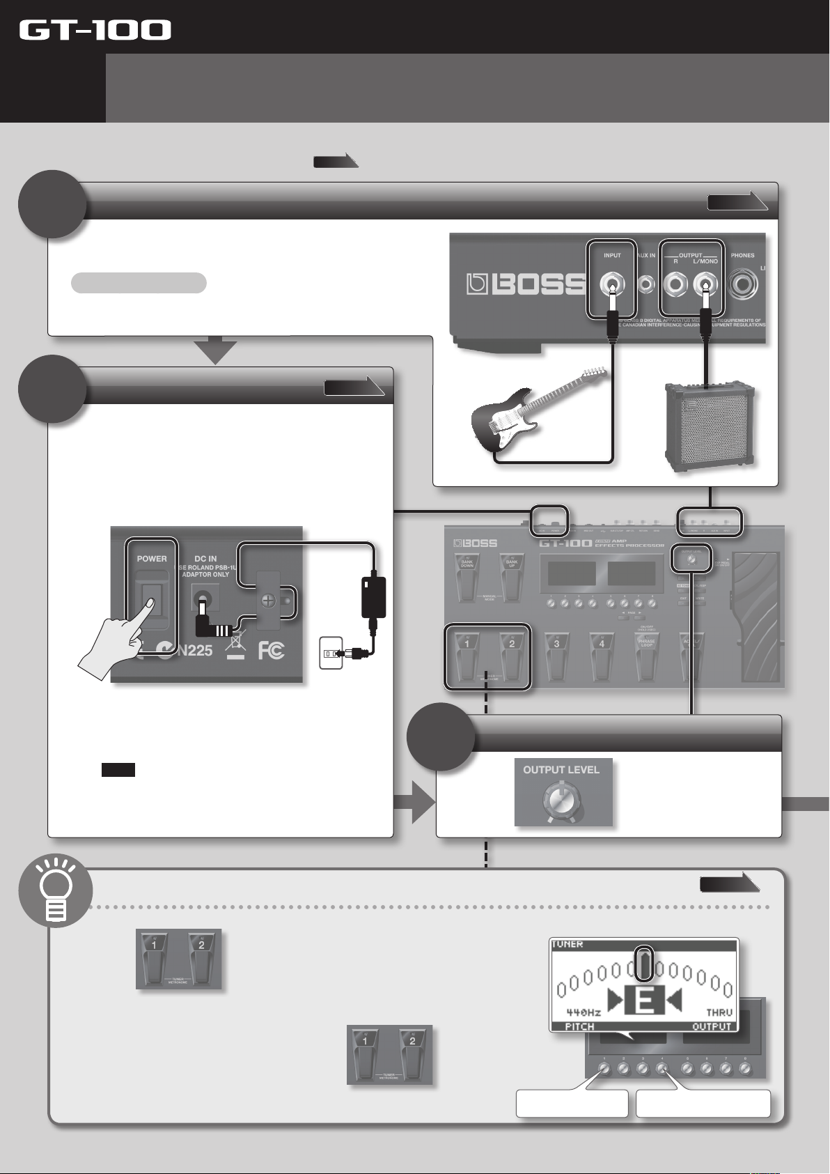
Connect your guitar and amp.
1
Connect your guitar and amp.
Minimize the volume!
Turn o the power to the GT-100 and your amp, and set the volume to the
minimum.
Turn on the power
For details, see
2
1. Connect the AC adaptor.
2. Turn the [POWER] switch on.
3. Turn on the power to your guitar amp.
page XX
page 24
symbol.
For details, see
page 22
* With the factory settings, the GT-100 will automatically
be switched o 10 hours after you stop playing or
operating the unit. If you don’t want the unit to turn o
automatically, change the “AUTO OFF” setting to “OFF” as
described on p. 42.
Note
The settings you were editing will be lost when the unit
is turned o. If you want to keep your settings, you must
save your settings before turning the unit o.
3
Convenient tuner function
1. Press simultaneously.
2. Play an open string, and tune it so that only the center
indicator in the screen is lit.
3. When you’re nished tuning, press
simultaneously once again.
Adjust the volume
Use to adjust the volume.
For details, see
Set the reference pitch Set the OUTPUT mode(p. 24)
page 24
8
Page 9
Quick Guide
Quick Guide Overview Outputting Sound Eects Saving
4
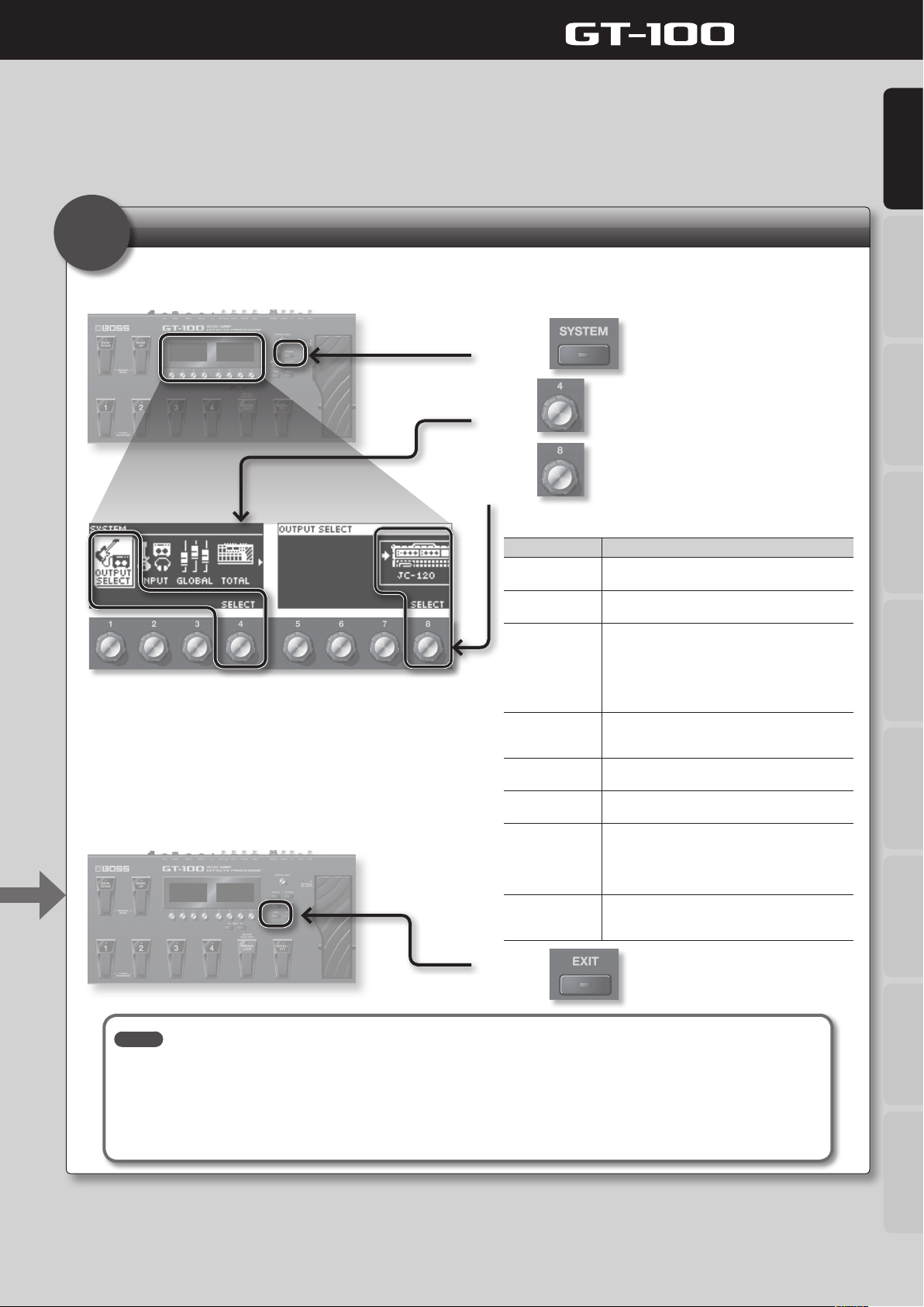
Specify the type of amp you’ve connected
In order to ensure optimal sound, you should specify the type of amp you’ve connected to the GT-100. Please take a moment to do
this.
1. Press .
2. Use to choose “OUTPUT SELECT.”
3. Use to select the type of amp you’re
using.
Value Explanation
JC-120
SMALL AMP
COMBO AMP
STACK AMP
JC-120 RETURN
COMBO RETURN
STACK RETURN
LINE/PHONES
Choose this setting if the GT-100 is connected to the
guitar input of a Roland JC-120 guitar amp.
Choose this setting if the GT-100 is connected to a
small guitar amp.
Choose this setting if the GT-100 is connected to the
guitar input of a combo-type guitar amp (i.e., a single
unit that contains the amp and speaker) other than
the JC-120.
For some types of guitar amps, the “JC-120” setting
might produce better results.
Choose this setting if the GT-100 is connected to the
guitar input of a stack-type guitar amp (i.e., one in
which the amp and speaker are separate units).
Choose this setting if the GT-100 is connected to the
RETURN jack of the JC-120.
Choose this setting if the GT-100 is connected to the
RETURN jack of a combo-type guitar amp.
Choose this setting if the GT-100 is connected to the
RETURN jack of a stack-type guitar amp. You should
also choose the “STACK RETURN” setting if you’re
using a guitar power amp together with a speaker
cabinet.
Choose this setting if you’re using headphones, or if
the GT-100 is connected to a keyboard amp, mixer, or
digital recorder.
Pedal Settings
System MIDI/USB Appendices
4. Press .
MEMO
• The SP Type parameter is valid only if the Output Select setting is set to “LINE/PHONES.” For the detail on SP TYPE parameter,
download “GT-100 Parameter Guide” (PDF le) from “GT-100” in the “Owner’s Manuals” list on the Roland website (http://www.roland.
com/support/en/).
• When using headphones, you won’t be able to obtain a sound that is typical of a guitar amp unless you turn on a preamp. We
recommend that you turn on a preamp whenever you’re using headphones. For the detail on PREAMP, refer to “GT-100 Parameter
Guide” (PDF le).
Now you’re ready to get started! The following pages explain how to play using the GT-100.
9
Page 10
Quick Guide
2
Playing
Now that you’re nished with the preparations, you can get started playing the GT-100.
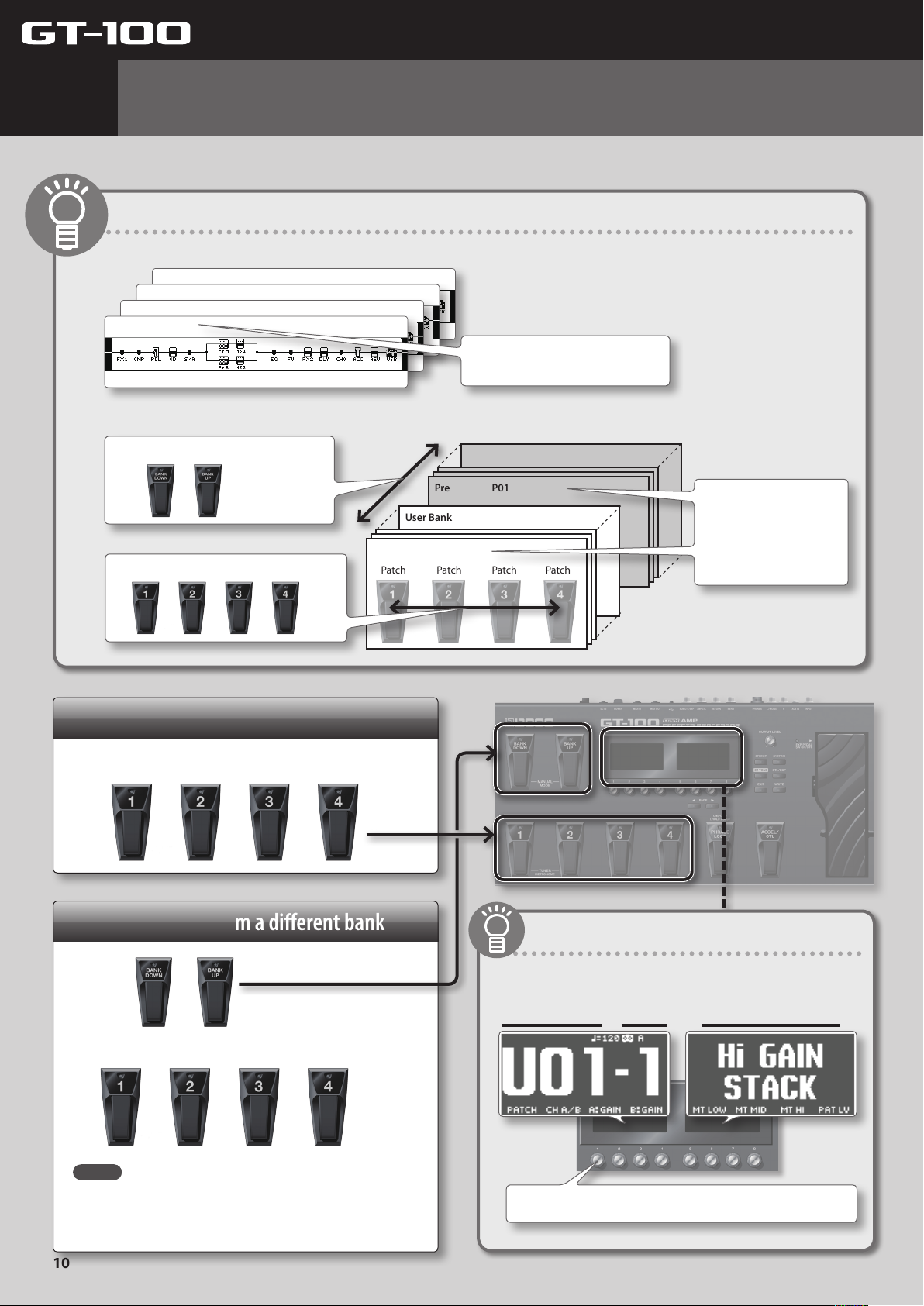
What is a Patch?
The GT-100 contains numerous eects. A combination of these eects and their settings is called a “patch.”
Patch U01-4
Patch U01-3
Patch U01-2
Patch U01-1
A “patch” is a combination of eects and
their settings.
The GT-100 comes with 400 patches; they are organized by bank and number, as follows.
Use the bank pedals to switch banks.
Use pedals 1 through 4 to switch numbers.
User Bank U50
User Bank
User Bank
User Bank U01
Patch Patch Patch Patch
Preset Bank P50
User Bank
User Bank
Preset Bank P01
You can’t save by overwriting
a patch in a preset bank.
You can save by overwriting
a patch in a user bank.
Selecting patches in the same bank
Press the pedal of the desired number.
Selecting patches from a dierent bank
1. Use to select the bank.
2. Press the pedal of the desired number.
Bank and number indication
The display shows the currently selected bank and number.
Bank Number Patch Name
MEMO
You can’t switch patches unless you’re in the Play screen (p. 11).
Press the [EXIT] button to return to the Play screen, and then
switch patches.
10
You can also switch patches by turning knob [1].
Page 11
Quick Guide
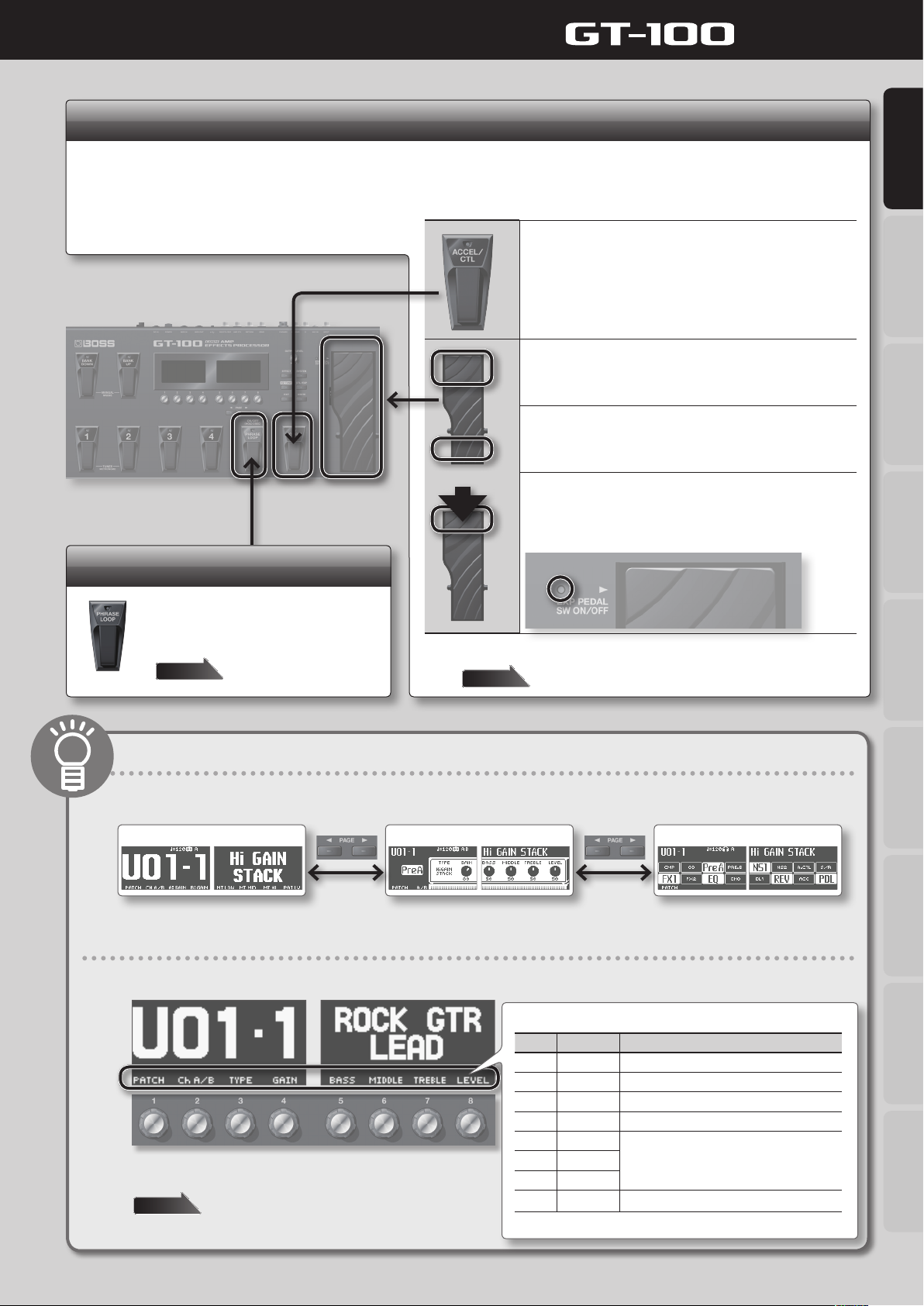
Using the pedals to control the eects
When you depress the [ACCEL/CTL] pedal, it will function as either an ACCEL pedal, which allows you to modify the sound by means of an
Accel eect (p. 19), or an ordinary CTL (control) pedal. The [EXP] pedal can be used to control Foot Volume, Wah, etc.
The function of each of these pedals can be assigned individually for each patch.
Quick Guide Overview Outputting Sound Eects Saving
Press the [ACCEL/CTL] pedal
When using the pedal for ACCEL (SOURCE MODE set to MOMENT; p. 33),
the function will be turned on when you depress the pedal (indicator
will light).
It will turn o when you release the pedal (the indicator will go out).
Depress the [EXP] pedal (press down on
the toe)
The [EXP] pedal’s value will increase.
Release the pedal (press down on the
heel)
The [EXP] pedal’s value will decrease.
Firmly press down on the toe
The EXP PEDAL SW function will turn on (the indicator will be lit).
Firmly press down once again to turn the function o (the indicator will
go out).
Phrase Loop
By operating the [PHRASE LOOP] pedal
you can create performances in which you
build up layers of sound by recording and
playing back in real time.
Page 18
You are free to assign the parameters that will be controlled by these pedals.
page 33
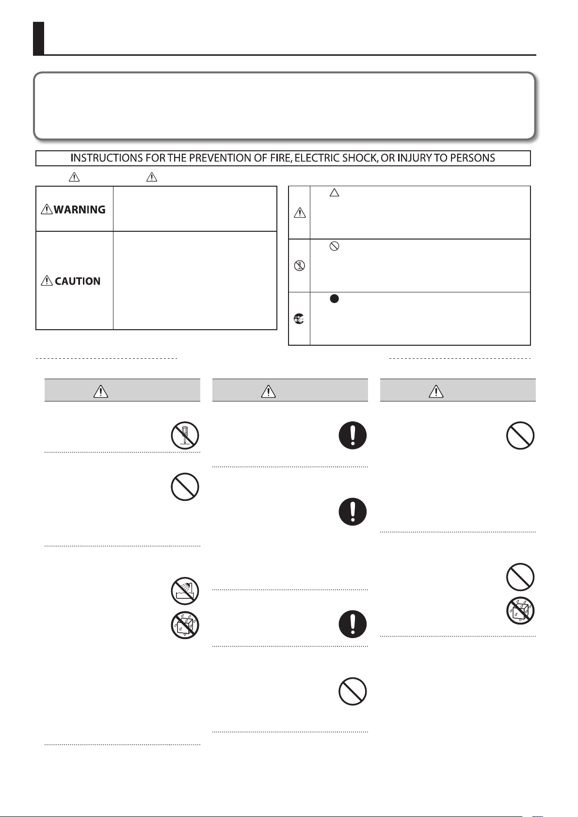
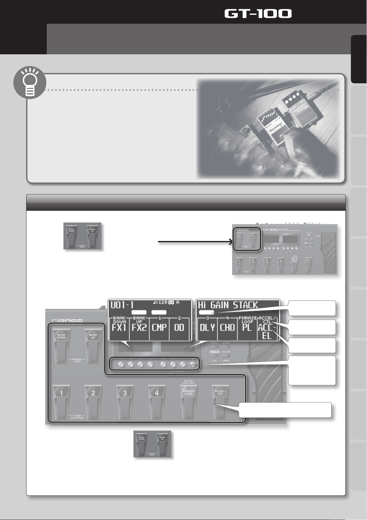
Switching the Play screen
The screen that appears when you turn on the GT-100’s power is called the “Play screen.” There are three dierent Play screens, as shown below.
To switch from one to the next, press the [PAGE] button.
Screen with the patch name shown large
Amp control screen Eect on/o status indication screen
What the eight knobs do
The eight knobs located below the displays control the functions shown at the bottom of the displays.
The functions assigned to each knob are displayed here.
Pedal Settings
System MIDI/USB Appendices
You can assign the Play screen knobs to control the parameters you
want.
page 35
Knob Function Explanation
[1] PATCH Selects patches.
[2] CH A/B Switches between channels (settings) A and B.
[3] A:GAIN Adjusts the distortion of preamp A.
[4] B:GAIN Adjusts the distortion of preamp B.
[5] MT LOW
[6] MT MID
[7] MT HI
[8] PAT LV Adjusts the volume.
Adjusts the low, mid, and high-frequency
ranges.
11
Page 12
Quick Guide
3
Editing: Basic Operation
Editing on the GT-100 is extremely simple; the procedure is always the same. Please take
a moment to learn the basic operations.
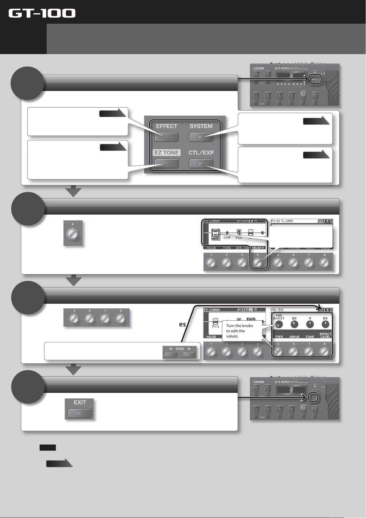
Choose what you’re going to edit
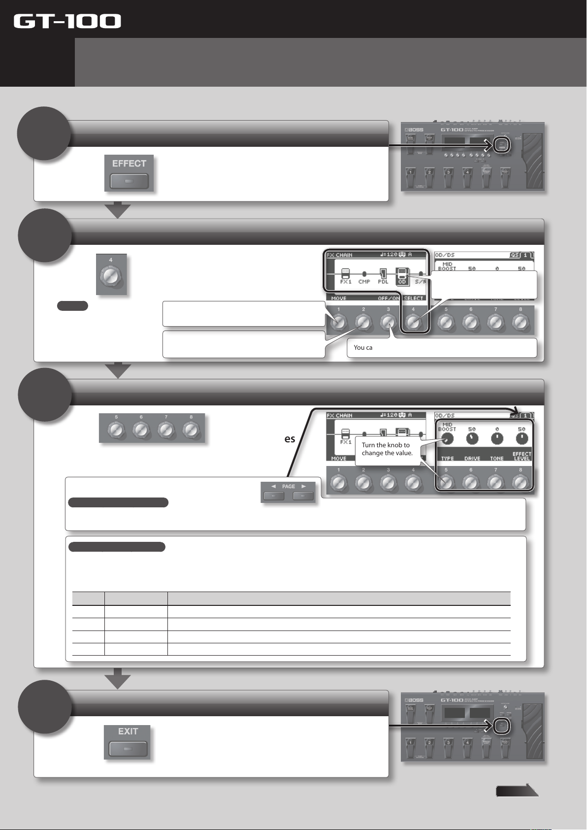
1
Press one of the following buttons.
Eect
Here you can edit the parameters of each eect.
EZ (Easy) Tone
Here you can create the desired tone simply by
choosing a musical style and the type of song you
have in mind. You can also customize the amp and
overdrive/distortion settings in an intuitive way.
Select an item
2
page 16
page 14
System
Here you can make settings that apply to the
entire GT-100, such as output settings and
phrase loop settings.
Control/Expression
Here you can assign the desired functions to the
[ACCEL/CTL] pedal, [EXP] pedal, and external
pedals.
page 40
page 33
3
4
Use to select an item shown in the left
display.
The screen shown here is an example of when you’ve pressed
the [EFFECT] button.
Edit the values
Use
shown in the right display.
If page tabs are shown in the screen, you can use the
[PAGE] buttons to move between tabs.
to edit the values
Exit the settings
Turn knob [4] to select the
desired item (the cursor will
move).
Turn the knobs
to edit the
values.
12
Press
You’ll be returned to the Play screen.
NOTE
The settings you’ve edited will be lost when you switch patches. If you want to keep the edited settings, you must save them as a user patch.
Next Page
.
Page 13
Quick Guide
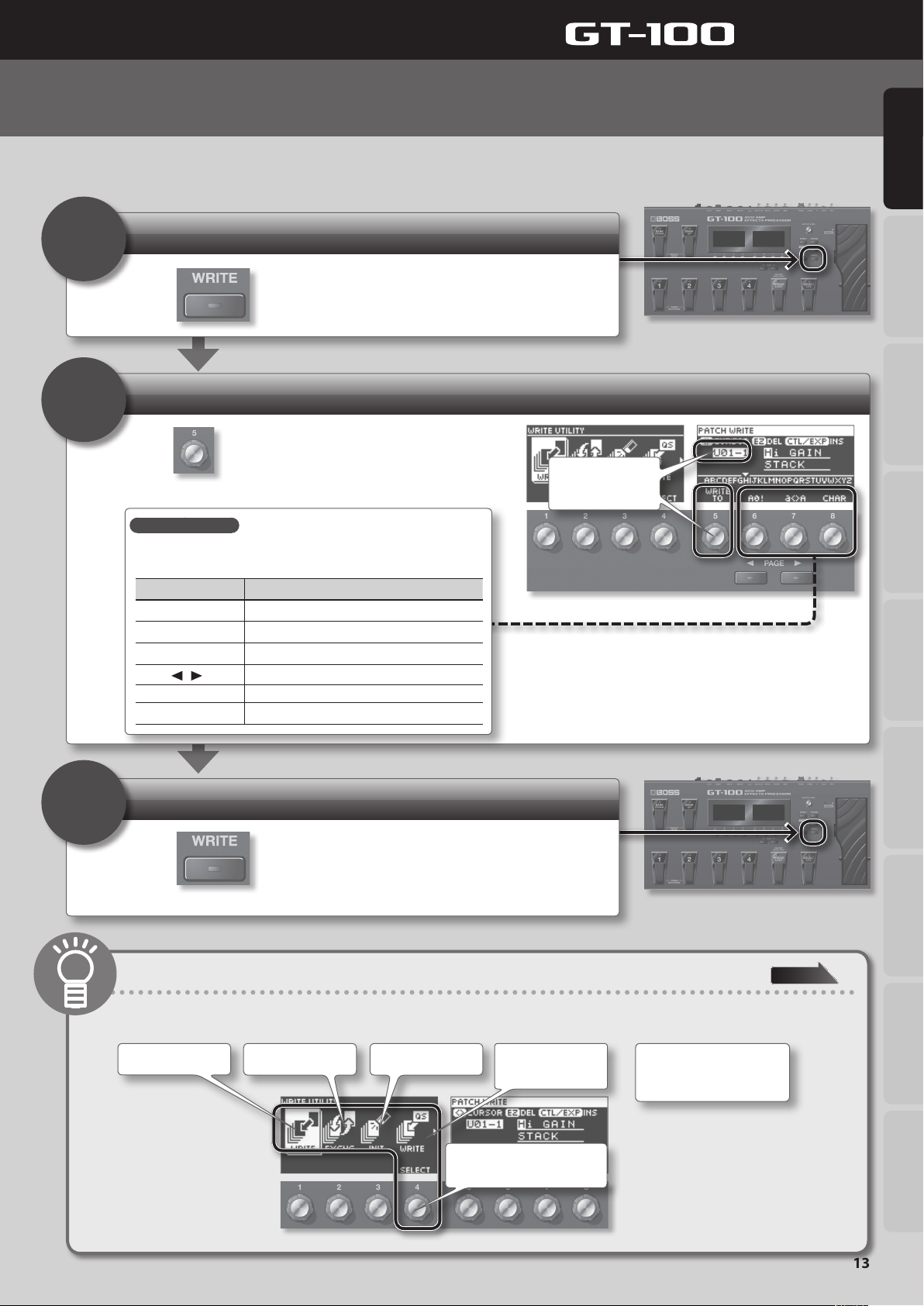
Editing: Saving a Patch
If you want to keep a patch you’ve edited, you must save (write) it as a user patch using the procedure described below. If you don’t save an
edited patch, your edits will be lost when you switch patches.
Access the Write menu
1
Press
Select the write destination
.
2
Use
(U01-1–U50-4).
Assigning a name
To edit the patch name, use knob [8] to move the cursor and use knob [8] to
change the character.
to select the write destination
Quick Guide Overview Outputting Sound Eects Saving
Turn the knob to
change the write
destination.
3
Controller Operation
Knob [6] Selects the type of characters
Knob [7] Switches between lowercase/uppercase characters
Knob [8] Changes the character
][ ] button
PAGE [
[EZ TONE] button Deletes one character
[CTL/EXP] button Inserts one character
Moves the cursor
Save
Press .
When the patch has been saved, you will return to the Play screen.
Types of saving
In the left display, you can choose the type of data that will be saved. (By default, the patch will be saved.)
And if you turn knob [4]...
Save
Exchange Initialize Save to User Quick
Settings (p. 31)
...
Pedal Settings
System MIDI/USB Appendices
page 30
Exchange or copy PREAMP
settings between channels
A and B.
Turn knob [4] to choose the
type of data to save.
13
Page 14
Quick Guide
4
1
2
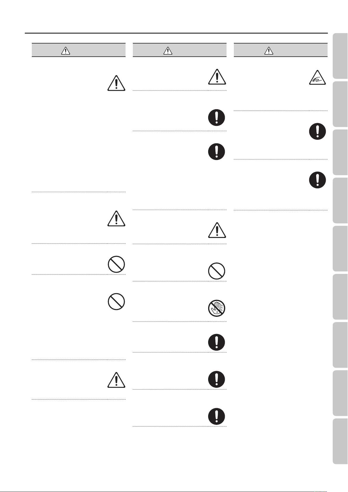
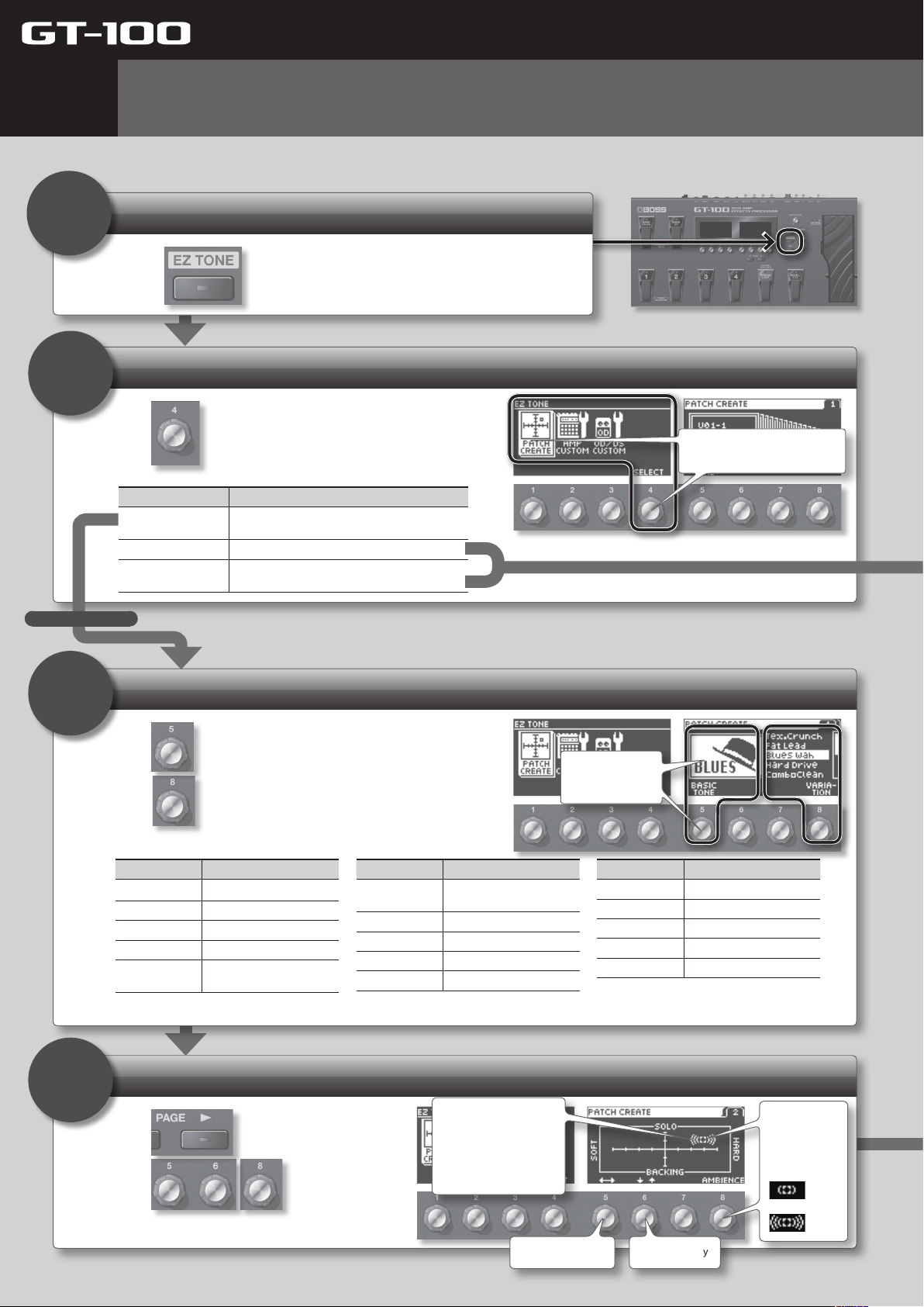
Editing: EZ (Easy) Tone
EZ (Easy) Tone lets you create your sound intuitively, simply by turning knobs as indicated in the screen.
If you want to edit the parameters of each eect in the patch, refer to “Editing: Editing the Eects” (p. 16).
Enter EZ (Easy) Tone mode
Press .
Select the type of editing
Use to select the type of editing
Menu Explanation
PATCH CREATE
AMP CUSTOM Lets you intuitively customize the amp.
OD/DS CUSTOM
Lets you easily create your sound starting from
your choice of musical style and type of song.
Lets you intuitively customize the overdrive/
distortion.
Turn knob [4] to select a menu
item (the cursor will move).
For PATCH CREATE
3
Use
and
* Upon selection of a variation, as described above, the unit will be set to the appropriate preamp type (p. 52). However, if PREAMP under PREFERENCE (p. 41) is set to
Select a musical style
to choose the basic tone,
to select a variation.
Basic tone Explanation
BLUES Blues sound
Soul Funk Soul and Funk sound
Jazz Jazz sound
LIVERPOOL British Rock
70’s Hard Rock
SYSTEM 1 through 3, the preamp type that has been set within will be retained. In such cases, there's no need to proceed to the next step, "4. Adjust the sound."
The Hard Rock sound
popular in the ’70s
Basic tone Explanation
80s METAL
MODERN METAL Modern Metal sound
West Coast West Coast sound
Fuzz Rock Fuzz
STUDIO Recording Studio
The Metal sound popular in
the ’80s
Turn the knobs
to edit the
values.
Basic tone Explanation
PROGRESSIVE Progressive
SURF ROCK Surf Rock sound
COUNTRY Country
Acoustic For Acoustic Guitar
Punk Pop Punk Pop
4
14
Adjust the sound
Use
Use
sound.
to switch screens.
to adjust the
Amount of distortion
Up: For soloing
Down: For backing
Left: Warm distortion
Right: Sharp distortion
Move horizontally
Resonance
Knob [8]
adjusts the
length of the
resonance.
: Less
: More
Move vertically
Page 15
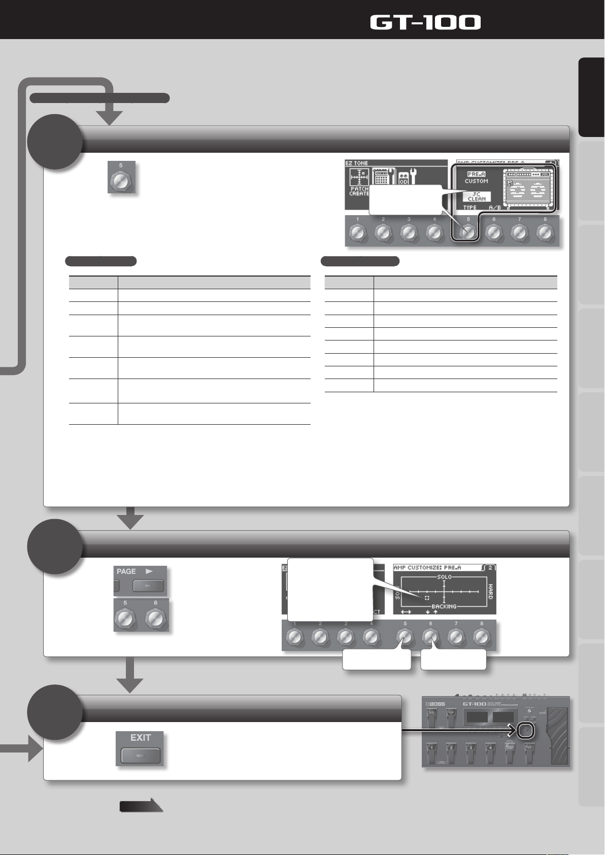
For AMP CUSTOM or OD/DS CUSTOM
Choose Amp or Drive
3
Quick Guide
Quick Guide Overview Outputting Sound Eects Saving
Use to select the type.
Initially, “CURRENT” will be displayed; then, below that the preamp type
or OD/DS type (p. 52) that is set for the current patch will be displayed.
For AMP CUSTOM
Type Explanation
JC CLEAN This models the sound of the Roland JC-120.
TW CLEAN This models a Fender Twin Reverb.
CRUNCH
COMBO DRIVE
COMBO LEAD
MS HiGAIN
MODERN
STACK
* In order to use AMP CUSTOM, you rst need to turn on PREAMP A or B,
whichever is currently selected.
This is a crunch sound that can faithfully reproduce the
nuances of picking.
This is a combo amp sound that it suited to sixties-style British
rock.
This is a lead sound of a combo tube amp typical of the late
‘70s to ‘80s.
This models the sound input to Input I on a Marshall 1959.
This is a trebly sound suited to hard rock.
This original high-gain amp delivers thick lows and intense
distortion while still preserving the sound’s clear denition.
Turn the knob to
change the type.
For OD/DS CUSTOM
Type Explanation
OD-1 This models the sound of the BOSS OD-1.
OD-2 This is an overdrive sound with high gain.
CRUNCH This is a crunch sound.
DS-1 This gives a basic, traditional distortion sound.
DS-2 This creates a heavier distortion sound.
METAL1 This is a metal sound with a characteristic midrange.
METAL2 This gives a heavy metal sound.
FUZZ This gives a basic, traditional fuzz sound.
* In order to use OD/DS CUSTOM, you rst need to turn on OD/DS.
4
5
Adjust the amount of distortion
Use to switch screens.
Use
to adjust the
distortion.
Finish editing
Press .
Amount of distortion
Up: For soloing
Down: For backing
Left: Warm distortion
Right: Sharp distortion
Move horizontally
Pedal Settings
System MIDI/USB Appendices
Move vertically
The edits you made here will be lost if you switch patches. If you want to keep the patch you created, press the [WRITE] button to save your edits as
a user patch.
page 13
15
Page 16
Quick Guide
5
1
2
Editing: Editing the Eects
You can edit the parameters of each eect in the patch. Here we’ll show an example of editing the distortion of the overdrive eect.
Enter Eect Edit mode
Press .
Select the eect that you want to edit
Turn knob [4] to select the eect
Use to select OD/DS.
MEMO
An eect can also be
selected by stepping on the
pedal that has been set in
Manual mode (p. 17).
Use knob [1] to move the position of the eect to
left or right.
(Only if the cursor is located at FX1 or FX2) Use
knob [2] to select the eect type for FX1 or FX2.
You can use knob [3] to turn the eect on/o.
(the cursor will move).
3
Edit the values
Use
shown in the right display.
Use the [PAGE] buttons to move between page tabs.
Convenient Quick Settings
If you select a page tab that shows “QS,” you’ll be able to easily call up settings (Quick Settings) that have been saved for each eect.
For details on how to save Quick Settings, refer to “Storing Settings by Eect (Quick Setting Write)” (p. 31).
What does each knob do?
The function (parameter) of each knob will dier depending on the eect. For a list of all parameters, download “GT-100 Parameter Guide” (PDF le) from
“GT-100” in the “Owner’s Manuals” list on the Roland website (http://www.roland.com/support/en/).
Switches the type of overdrive/distortion
Knob Operation Explanation
[5] TYPE Switches the type of overdrive/distortion.
[6] DRIVE Adjusts the amount of overdrive/distortion.
[7] TONE Adjust the tone quality. Higher values produce a sharper tone.
[8] EFFECT LEVEL Adjusts the volume when the eect is being applied.
to edit the values
Turn the knob to
change the value.
Finish editing
4
Press
You’ll be returned to the Play screen.
The edits you made here will be lost if you switch patches. If you want to keep the patch you created, press the [WRITE] button to save your edits as a user patch.
16
.
page 13
Page 17
Quick Guide
6
Advanced: Manual Mode
This section explains more advanced uses of the GT-100.
What Is Manual Mode?
Manual mode lets you use the GT-100’s pedals to turn on/o
individual eects within a patch.
You can use this just as though you were individually switching
on/o several compact eects units in a pedalboard.
* In Manual mode, P.LOOP PEDAL and ACC/CTL PDL, which
can be assigned to ASSIGN 1--8 (p. 37) under ”Pedal Settings
(Control/Expression)” (p. 33), will be invalidated.
Using the pedals to turn each eect on/o (Manual mode)
Quick Guide Overview Outputting Sound Eects Saving
1. Press simultaneously.
2. Use the pedals to turn each eect on/o.
On/o status
Pedal name
Eect name
You can assign the
desired eects unit
to each pedal.
Use the pedals to turn each eect on/o.
Pedal Settings
System MIDI/USB Appendices
3. To exit Manual mode, press simultaneously once again.
* If PHRASE LOOP PEDAL FUNC (p. 32) is set to “PHRASE LOOP,” you won’t be able to assign anything other than PHRASE LOOP (“PL”) to the
[PHRASE LOOP] pedal. If you want to assign any other function, you must turn PHRASE LOOP PEDAL FUNC o.
17
Page 18
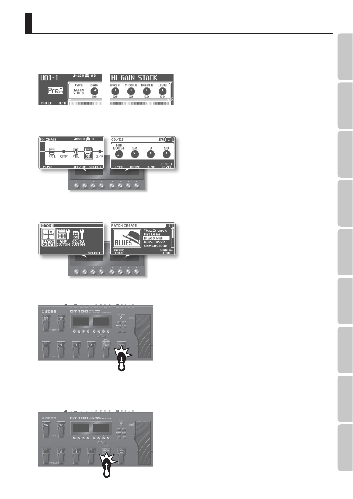
7
Advanced: Phrase Loop
By operating the [PHRASE LOOP] pedal, you can carry out recording and playback in real
time to create layered performances.
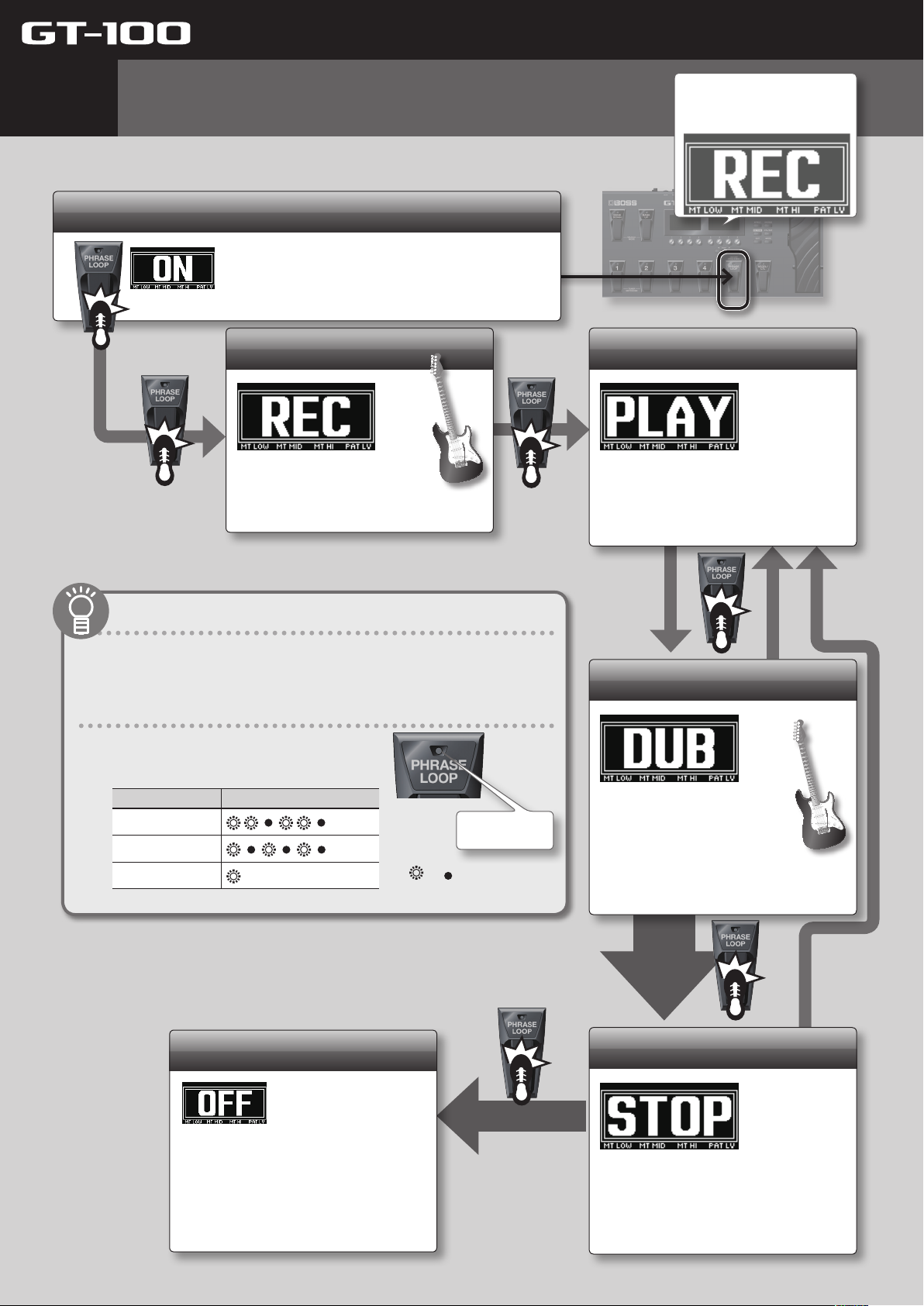
Enter Phrase Loop mode
Quick Guide
Each time you press the pedal, the
right display will show the phrase
loop status for a predetermined
amount of time.
Hold down the pedal for two seconds or
longer; the Phrase Loop function will turn
on, and will be in the standby condition.
Record
Press the pedal once again,
and record your guitar
performance.
About Phrase Loop
The recording time is 38 seconds in monaural.
To make settings for Phrase Loop, see “Setting Phrase Loop” (p. 32).
About the pedal’s indicator
The pedal’s indicator will blink or light in a dierent
pattern according to the Phrase Loop status.
Status Indicator illumination pattern
Standby
Recording/Overdub
Playback
(stays lit)
...
...
: lit : unlit
Indicator
Loop playback
Play back the loop.
Pressing the pedal will switch to
overdubbing.
Overdub
Record additional layers
while playing back the
loop.
Press the pedal to switch
to playback.
18
Clear/Exit
To clear the phrase and exit Phrase
Loop, hold down the pedal for at
least two seconds while stopped.
* The recorded content will be erased when you exit
Phrase Loop.
* The recorded content will not be saved.
Press twice
Stop
Hold down two seconds or longer
To stop, press the pedal twice in
succession during overdubbing or
loop playback.
* Press the pedal twice within one second.
Page 19
Quick Guide
8
1
2
Advanced: Accel Eect
The GT-100 has six dierent Accel eects that make the sound more aggressive when you press the [ACCEL/CTL] pedal.
First, you need to set [CTL/EXP]: ACCEL/CTL FUNC to ACCEL, and set SOURCE MODE to MOMENT (p. 33).
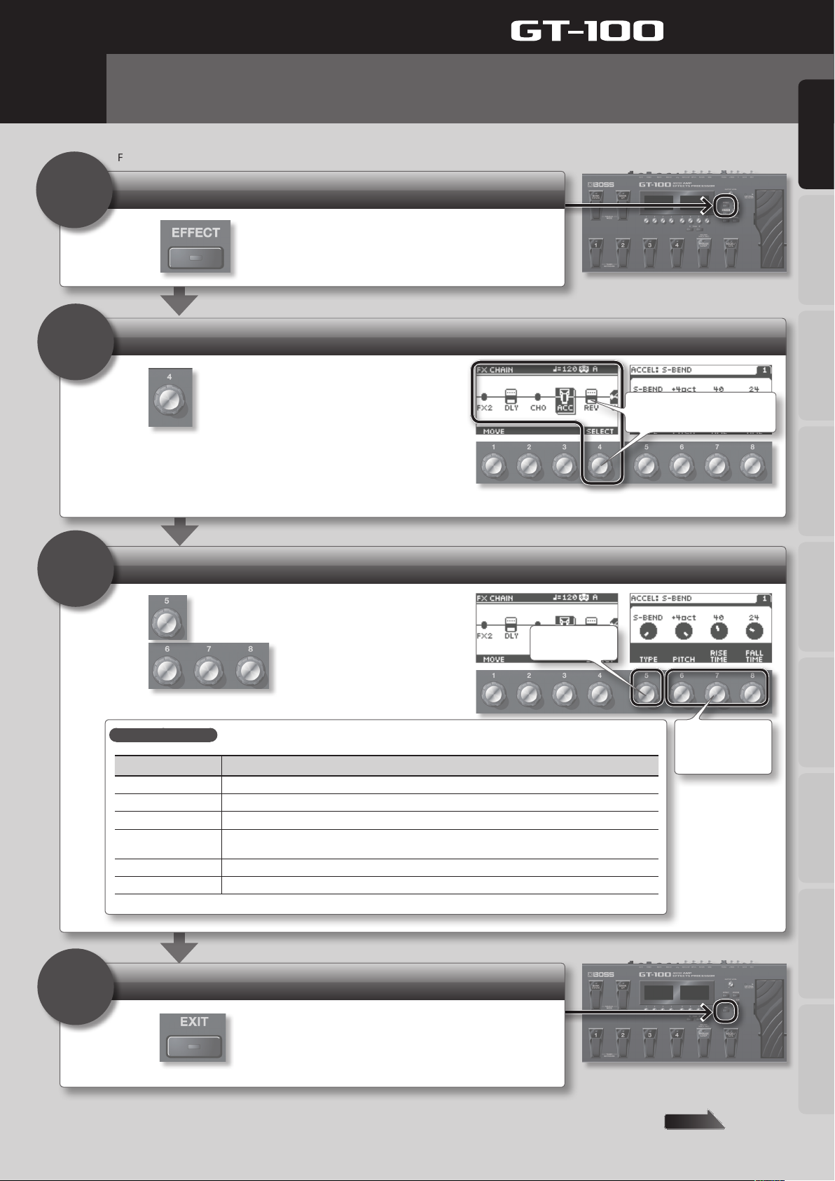
Enter Eect Edit mode
Press .
Select the ACCEL eect
Turn knob [4] to select the eect
Use to select “ACCEL.”
(the cursor will move).
Quick Guide Overview Outputting Sound Eects Saving
3
Select the eect
Use
Use
ACCEL eects types
Type Eect
S-BEND Applies intense bending.
LASER BEAM Produces a laser beam-like sound.
RING MODULATOR Produces a metallic sound, creating the impression that the sound is being focused.
TWIST
WARP Produces a dream-like sound.
FEEDBACKER Generates feedback performance.
to select the type of ACCEL eect.
to adjust the sound.
Produces an aggressive sense of rotation. Using this in conjunction with distortion will produce an even
wilder sense of rotation.
Select the type
Pedal Settings
Adjust the sound.
(Depends on the
type.)
System MIDI/USB Appendices
Exit the settings
4
Press
You’ll be returned to the Play screen.
The settings you made will be lost if you switch patches. If you want to keep the patch you created, save it as a user patch.
.
page 13
19
Page 20
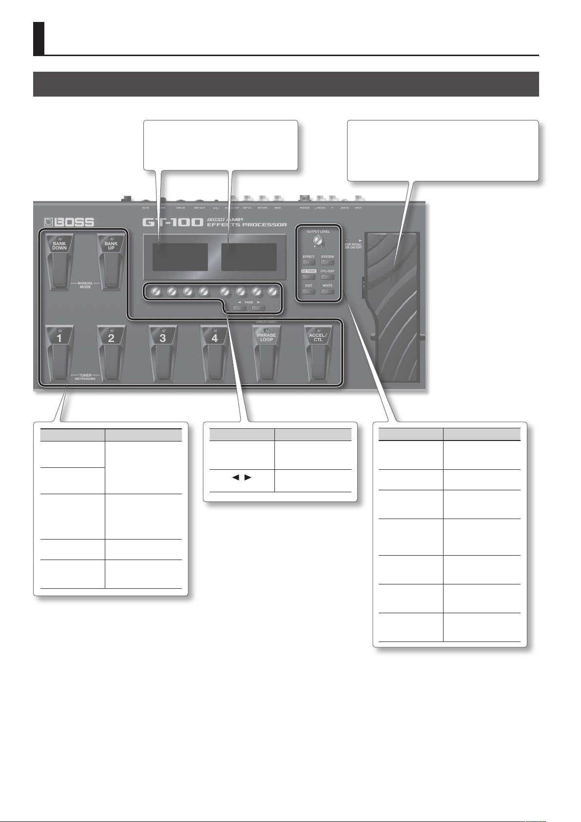
Panel Descriptions
Front Panel
Display
Various information about the GT-100 is shown
here.
[EXP] pedal
Controls volume, wah, and other parameters. By strongly
pressing the toe end of the pedal, you can turn volume control
or wah on/o.
* When you operate the expression
pedal, please be careful not to get
your ngers pinched between
the movable part and the panel.
In places where small children
are present, make sure that an
adult provides supervision and
guidance.
Pedal Explanation
[BANK UP]
[BANK DOWN]
Number pedals 1–4
[PHRASE LOOP]
[ACCEL/CTL] pedal
Switch the patch bank
(p. 10) or turn Manual
mode on/o (p. 17).
These switch the patch
number (p. 10). Press the
[1]/[2] pedals simultaneously to turn the tuner
function on/o (p. 24).
Starts the Phrase Loop
function (p. 18).
Starts the Accel function
(p. 19), or can be used as a
control pedal.
Knob/Button Explanation
Parameter knobs
[1]–[8]
][ ]
PAGE [
button
Adjust the parameter
values shown in the
display.
Switch pages in the
display.
Knob/Button Explanation
[OUTPUT LEVEL]
knob
[EFFECT] button
[SYSTEM] button
[EZ TONE] button
[CTL/EXP] button
[EXIT] button
[WRITE] button
This adjusts the volume
level at the OUTPUT jack
and the PHONES jack.
Lets you make eect
settings(p. 16).
Lets you make overall
settings for the entire
GT-100 (p. 40).
Lets you easily create a
sound by specifying a
musical style or character
of song (p. 14).
Lets you make control
pedal and expression
pedal assignments (p. 33).
Returns you to the previous screen, or cancels the
previous operation.
Saves patch settings,
or lets you exchange or
copy data (p. 30).
20
Page 21
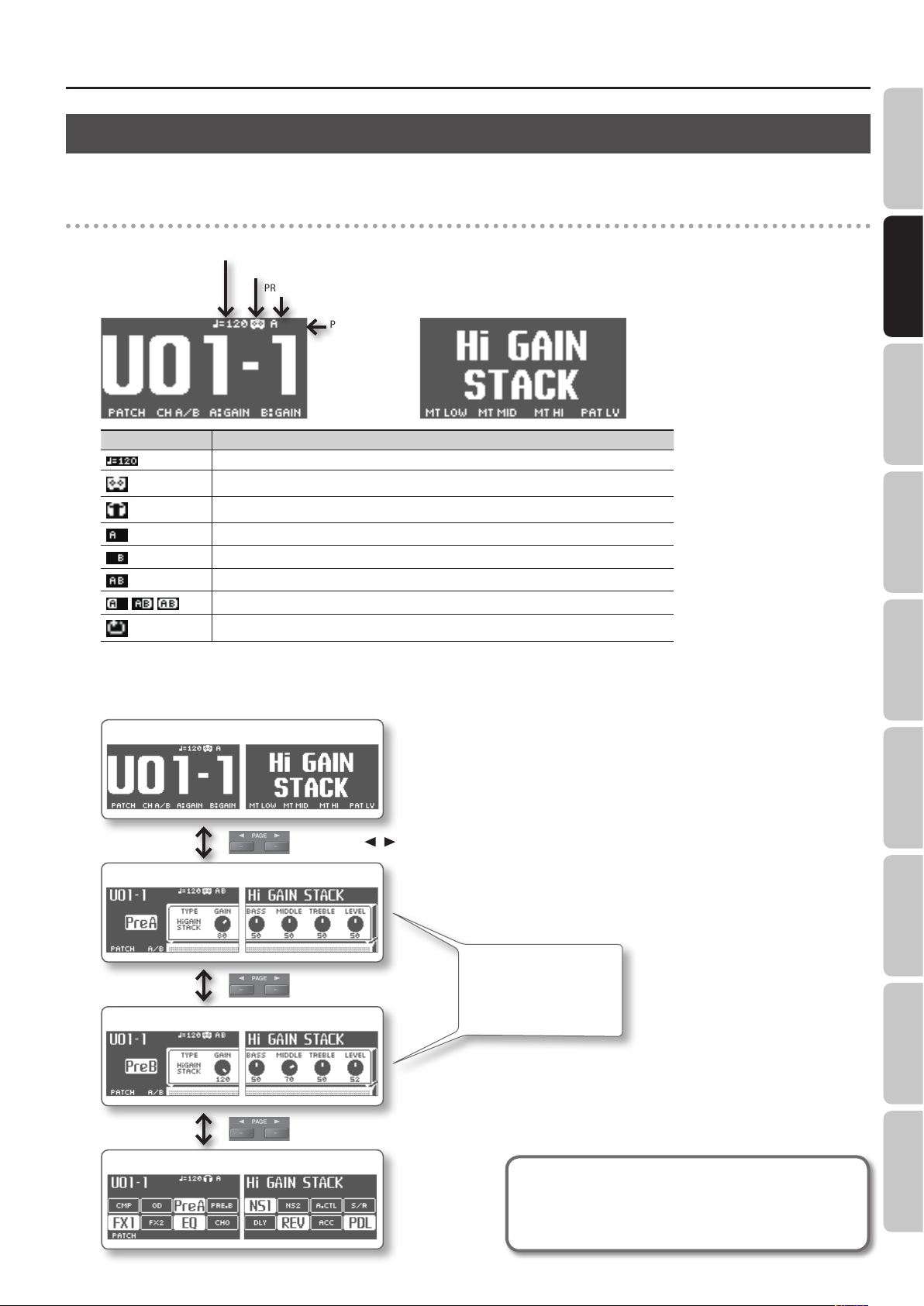
About the Play Screen
The screen that appears after you turn on the power is called the Play screen.
Icons in the display
Left display
Bank – Number
Icon Explanation
, ,
MASTER BPM
OUTPUT SELECT setting
PREAMP Channel
PHRASE LOOP on
Displays the Master BPM (*1) value for each patch.
This is displayed when OUTPUT SELECT (p. 9) is set to anything other than LINE/PHONES.
This is displayed when OUTPUT SELECT (p. 9) is set to LINE/PHONES.
When the DIVIDER (p. 27) mode is Single, preamp channel “A” is selected.
When the DIVIDER (p. 27) mode is Single, preamp channel “B” is selected.
This is displayed if the DIVIDER (p. 27) mode is Dual.
This icon is highlighted if the SOLO SW (*1) is on.
This is displayed when the PHRASE LOOP (p. 18) is On.
Panel Descriptions
Quick Guide Overview Outputting Sound Eects Saving
Right display
*1 For the detail on the Master BPM and SOLO SW, download “GT-100 Parameter Guide” (PDF le) from “GT-100” in the “Owner’s Manuals” list on the Roland website (http://
www.roland.com/support/en/).
Types of Play screens
Screen with the patch name shown large
Use the PAGE [ ][ ] buttons to switch.
Amp control screen (Ch. A)
If DIVIDER (p. 27) is set to
SINGLE, only the screen of the
currently selected channel
(not both channels) will be
Amp control screen (Ch. B)
shown.
Pedal Settings
System MIDI/USB Appendices
Eect on/o status indication screen
The explanations in this manual include illustrations that depict what
should typically be shown by the display.
Note, however, that your unit may incorporate a newer, enhanced version
of the system (e.g., includes newer sounds), so what you actually see in
the display may not always match what appears in the manual.
21
Page 22

Panel Descriptions
Rear Panel (Connections)
INPUT jack
Connect your guitar.
AUX IN jack
Use a stereo mini-plug to
connect your audio player.
PHONES jack
Connect headphones
(sold separately).
LIFT/GND switch
Normally, you can leave this set to the
GND position.
If you’ve connected the EXT LOOP
(SEND/RETURN) jacks to an amp, a
ground loop may occur, producing
noise. If this occurs, you may be able
to eliminate the noise by moving this
switch to the LIFT position.
EXT LOOP SEND/
RETURN jack
Connect to external eects
processor or amp.
OUTPUT jacks
Connect these to your guitar amp or mixer.
If using a mono connection, use only the “L”
jack.
AMP CTL jack
If you’re using the Amp Control function (p. 28),
connect this to the channel switching jack of
your guitar amp.
* For some models of guitar amps, this might
not be usable.
* To prevent malfunction and equipment failure, always turn down the volume, and turn o all the units before making any connections.
* When connection cables with resistors are used, the volume level of equipment connected to the inputs (INPUT , AUX IN, RETURN jacks) may be
low. If this happens, use connection cables that do not contain resistors.
22
SUB CTL 1, 2/SUB EXP jack
You can control various parameters by connecting
an expression pedal (such as the separately available
Roland EV-5) or a foot switch (BOSS FS-5U, FS-6;
available separately) here (p. 33).
* Use only the specied expression pedal (Roland
EV-5, BOSS FV-500L, or FV-500H sold separately). By
connecting any other expression pedals, you risk
causing malfunction and/or damage to the unit.
* Only FOOT VOLUME can be assigned to the external
expression pedal (SUB EXP) (p. 33).
* You can’t simultaneously connect both a foot switch
and an expression pedal.
Page 23

Panel Descriptions
Quick Guide Overview Outputting Sound Eects Saving
MIDI jack
Connect these to MIDI
devices so that MIDI data can
be transmitted and received
(p. 47).
[POWER]
switch
Turns the unit on
and o.
DC IN jack
Connect the included AC adaptor here.
Place the AC
adaptor so the side
with the indicator
(see illustration) faces
upwards and the side
with textual information
faces downwards.
The indicator will light
when you plug the
AC adaptor into an AC
outlet.
To prevent the inadvertent disruption
of power to your unit (should the
plug be pulled out accidentally), and
to avoid applying undue stress to the
DC IN jack, anchor the power cord
using the cord hook, as shown in the
illustration.
Security Slot ( )
Connect a commercially available
anti-theft security cable here.
http://www.kensington.com/
USB port
Use a USB cable to connect a computer to this
connector and enable exchange of data between the
GT-100 and the computer (p. 49).
About USB cap
If you want to connect a USB cable, detach the USB cap
that covers the USB port. Leave the USB cap in place
when you’re not using the USB port.
Grounding Terminal
Connect the ground cable here.
* Depending on the circumstances of a particular setup, you may experience a discomfort-
ing sensation, or perceive that the surface feels gritty to the touch when you touch this
device, or the metal portions of other objects, such as guitars. This is due to an innitesimal
electrical charge, which is absolutely harmless. However, if you are concerned about
this, connect the ground terminal (see gure) with an external ground. When the unit is
grounded, a slight hum may occur, depending on the particulars of your installation. If you
are unsure of the connection method, contact the nearest Roland Service Center, or an
authorized Roland distributor, as listed on the “Information” page.
Unsuitable places for connection
• Water pipes (may result in shock or electrocution)
• Gas pipes (may result in re or explosion)
• Telephone-line ground or lightning rod (may be dangerous in the event of lightning)
Pedal Settings
System MIDI/USB Appendices
23
Page 24

Outputting Sounds
Switching the Unit On and O
Switching the Unit On
* Once everything is properly connected (p. 22), be sure to follow
the procedure below to turn on their power. If you turn on
equipment in the wrong order, you risk causing malfunction or
equipment failure.
* Before turning the unit on/o, always be sure to turn the volume
down. Even with the volume turned down, you might hear some
sound when switching the unit on/o. However, this is normal
and does not indicate a malfunction.
* This unit is equipped with a protection circuit. A brief interval (a
few seconds) after turning the unit on is required before it will
operate normally.
1. Press the GT-100’s [POWER] switch to turn on the power.
2. Turn on the power of the connected guitar amp.
Tuning the Guitar (TUNER)
1. Simultaneously press pedals [1] and [2].
The tuner function and the metronome function will turn on. The
left display will show the “TUNER” screen.
2. Turn knob [1] to specify the reference pitch.
3. Turn knob [4] to specify how the guitar sound will be
output while you’re using the tuner.
Switching the Unit O
1. Before turning o the power, conrm the following.
• Have you minimized the volume of the connected equipment?
• Have you saved any patches containing settings that have been
changed? “Saving a Patch (PATCH WRITE)” (p. 30)
2. Turn o the power of your guitar amp and any other
connected equipment.
3. Hold down the GT-100’s [POWER] switch for several
seconds to turn o the power.
Adjusting the Output Level
1. Adjust the GT-100’s output level with the [OUTPUT LEVEL]
knob.
Specifying the Output Device
Parameter Value Explanation
[1] PITCH 435 Hz–445 Hz Species the reference pitch.
Sound will not be output
while tuning.
While tuning, the sound of
the guitar being input to the
GT-100 will be output without
change. All eects will be o.
Allows you to tune while
hearing the current eect
sound.
OFF
THRU
MUTE
BYPASS
TUNER
OUTPUT
ON
TUNER
[4] OUTPUT
MUTE
BYPASS
THRU
EXP
pedal
4. Play an unfretted note on the string that you want to
tune, and tune the string until the desired note name is
shown in the display.
5. While watching the screen, tune the string until only the
middle indicator is lit.
Repeat steps 4–5 to tune all strings.
(Output Select)
You’ll need to specify the type of device (amp) that’s connected to
the OUTPUT jacks. The GT-100 will apply an internal adjustment so
that the output will sound optimal on the system you’re using.
Reference
For details on how to make this setting, refer to”Specify the type
of amp you’ve connected” (p. 9)
24
MEMO
If you’re tuning a guitar that’s equipped with a tremolo arm,
tuning one string may cause other strings to drift. If so, start by
tuning the strings approximately, so that the correct note names
are displayed; then repeatedly tune each string until all strings
are in tune.
Page 25

Outputting Sounds
6. Simultaneously press pedals [1] and [2] to return to the
Play screen.
You can also return to the Play screen by pressing the [EXIT] button.
MEMO
You can also turn the tuner on/o by pressing the number pedal
of the same number as the currently selected patch. For details,
refer to “Adjusting the [EXP] pedal” (p. 36)”Switching Settings with
the Number Pedals” (p. 35).
Using the Metronome
1. Simultaneously press pedals [1] and [2].
The tuner function and the metronome function will turn on. The
right display will show the “METRONOME” screen.
Selecting a Tone (Patch Change)
A combination (or set) of eects together with a group of
parameter settings is called a “patch.”
How a Patch Is Structured
The GT-100 can store 400 dierent patches in memory, organized
by bank and number as shown below.
Preset Bank P50
User Bank
User Bank
Preset Bank P01
User Bank U50
User Bank
User Bank
User Bank U01
User Banks (U01–U50)
Newly created eects settings are saved in the User banks. Patches
in these banks are called “User patches.”
A “U” appears in the display when a User patch is selected.
Quick Guide Overview Outputting Sound Eects Saving
2. Use knobs [5]–[8] to specify the metronome settings.
Parameter Value Explanation
[5] TEMPO 40–250
1/1–8/1,
[6] BEAT
[7] OFF/ON OFF, ON Turns the metronome on/o.
[8] LEVEL 0–100
* The metronome sound is output through the OUTPUT jack and
the PHONES jack.
* Changing the TEMPO will also change the MASTER BPM. For the
detail on MASTER BPM, refer to “GT-100 Parameter Guide” (PDF
le).
1/2–8/2,
1/4–8/4,
1/8–8/8
Species the tempo of the
metronome.
Selects the time signature.
Adjusts the volume of the
metronome.
3. Simultaneously press pedals [1] and [2] to return to the
Play screen.
You can also return to the Play screen by pressing the [EXIT] button.
Bank
Number
Preset Banks (P01–P50)
The Preset banks contain eect settings that make full use of the
features the GT-100 has to oer. The patches in these banks are
called “Preset patches.” When you change the settings of a Preset
patch, save the result as a User patch. Preset patches cannot be
overwritten.
A “P” appears in the display when a Preset patch is selected.
Bank
Number
Pedal Settings
System MIDI/USB Appendices
25
Page 26

Outputting Sounds
Using the Pedal to Select the Patch
Patches are switched by selecting a “bank” (U01–U50, P01–P50) and
“number” (1–4).
* On the GT-100, you cannot switch patches in any screen other
than the Play screen. Press [EXIT] to return to the Play screen
(p. 21).
1. Select a bank.
Use the [BANK UP]/[BANK DOWN] pedals to select a bank.
2. Select a patch within the selected bank.
Use pedals [1]–[4] to select a patch within the bank you selected in
step 1.
MEMO
When selecting a patch, even if a new bank is selected, the
patch is not switched until you also choose the number. If you
want to be able to switch patches merely by selecting a dierent
bank, adjust the BANK CHG MODE (p. 41) setting.
Using the Knobs to Select a Patch
You can also use knob [1] to select a patch.
* You can change the function of the knobs (p. 41).
26
Page 27

Creating Sounds (Eects)
Setting the Eects
Use the left and right displays and knobs [1]--[8] to edit the settings
of the internal eects.
Reference
For details on the basic procedures for manipulating eects,
refer to ”Editing: Editing the Eects” (p. 16).
Specifying the Divider and Mixer Modes
Within the eect chain, the point where the signal is split into
channels “A” and “B” is called the “divider,” and the point where the
two signals are recombined is called the “mixer.”
You can use the divider to switch between channels “A” and “B,” to
assign strongly picked notes and softly picked notes to dierent
channels, or to assign dierent frequency bands of your guitar
sound to dierent channels.
The mixer lets you adjust the volume balance of channels “A” and “B,”
place them in the stereo eld, or slightly delay the sound of channel
“B” to produce a spacious sound.
DIVIDER MIXER
Divider settings
1. Press the [EFFECT] button.
2. Use knob [4] to select “DIVIDER.”
3. Use knobs [5]–[8] and the PAGE [ ][ ] buttons to make
settings.
Dual mode settings
If you selected “DUAL” with knob [5]
Con-
Parameter Value Explanation
troller
Page 2
CH. A
[5]
DYNAMIC
CH. A
[6]
DYNAMIC
SENS
[7] CH. A FILTER
CH. A CUTOFF
[8]
FREQ
Page 3
CH. B
[5]
DYNAMIC
CH. B
[6]
DYNAMIC
SENS
[7] CH. B FILTER
CH. B CUTOFF
[8]
FREQ
OFF DYNAMIC will not be used.
POLAR+
POLAR-
0–100
OFF The lter will not be used.
LPF
HPF
100 Hz–2 kHz Cuto frequency
OFF DYNAMIC will not be used.
POLAR+
POLAR-
0–100
OFF The lter will not be used.
LPF
HPF
100 Hz–2 kHz Cuto frequency
Only notes picked more
strongly than the DYNAMIC
SENS setting will be output.
Only notes picked more
softly than the DYNAMIC SENS
setting will be output.
Species the picking
sensitivity.
Only the region below the
cuto frequency will be
output.
Only the region above the
cuto frequency will be
output.
Only notes picked more
strongly than the DYNAMIC
SENS setting will be output.
Only notes picked more
softly than the DYNAMIC SENS
setting will be output.
Species the picking
sensitivity.
Only the region below the
cuto frequency will be
output.
Only the region above the
cuto frequency will be
output.
Quick Guide Overview Outputting Sound Eects Saving
Pedal Settings
Con-
Parameter Value Explanation
troller
Page 1
SINGLE
[5] MODE
DUAL
Use only one channel, either
“A” or “B.”
Use the two channels “A” and
“B.”
Single mode settings
If you selected “SINGLE” with knob [5]
Con-
Parameter Value Explanation
troller
Page 1
[6] CH SELECT CH. A, CH. B Selects the channel to use.
System MIDI/USB Appendices
27
Page 28

Creating Sounds (Eects)
Mixer settings
1. Press the [EFFECT] button.
2. Use knob [4] to select “MIXER.”
3. Use knobs [5]–[7] to make settings.
Con-
Parameter Value Explanation
troller
STEREO
[5] MODE
L/R PAN
CH A/B
[6]
BALANC
[7] SPREAD 0–100
100:0–0:100
Using Amp Control
Channels “A” and “B” will be
mixed and output in stereo.
Channels “A” and “B” will be
assigned respectively to the L
and R OUTPUT jacks.
Adjusts the volume balance of
channels “A” and “B.”
* This is shown only if DIVIDER
MODE is set to “DUAL.”
Slightly delays the sound of
channel “B” to make the sound
more spacious.
* This is shown only if DIVIDER
MODE is set to “DUAL.”
4. Use knob [5] to switch the setting on/o.
Con-
Parameter Value Explanation
troller
Page 4
GT-100
(AMP CONTROL jack)
OFF
Guitar Amp
[5] AMP CONTROL
ON
(Channel switching jack)
GT-100
(AMP CONTROL jack)
By connecting your guitar amp’s channel switching jack to the GT100’s AMP CONTROL jack, you can then use Amp Control to switch
the amp channel.
This combining of the GT-100 and the amp channels allows you
to get an even wider variety of distortion sounds. Since the Amp
Control setting is handled as one of the eects parameters saved to
each individual patch, it allows you to switch guitar amp channels
with each patch.
1. Press the [EFFECT] button.
2. Use knob [4] to select “MASTER SETTING”.
Guitar Amp
(Channel switching jack)
* To determine how the amp channels are switched when the
circuit is open and shorted, refer to the amp owner’s manual, or
actually conrm the sounds by operating the amp.
* Note that, depending on the circuitry of the channel switching
jack in the guitar amp used, the Amp Control function may not
operate.
* Since this is a single mono plug, it can’t switch a three-channel
amp.
MEMO
With Amp Control, not only can you switch amp channels,
you can also use it to switch the amp’s eects on and o, like a
footswitch controller.
3. Press the PAGE [ ] button to access page 4.
28
Page 29

Creating Sounds (Eects)
Using Send/Return
You can connect an external eects processor between the SEND
jack and RETURN jack, and use it as one of the GT-100’s eects
processors.
The sound that is input to SEND/RETURN within the eect chain will
be output to the SEND jack. The sound that is input via the RETURN
jack will be input to SEND/RETURN within the eect chain.
1. Press the [EFFECT] button.
2. Use knob [4] to select “SEND/RETURN.”
3. Use knobs [5]–[8] to make settings.
Con-
Parameter Value Explanation
troller
The input to SEND/RETURN within the
eect chain will be output to the SEND
jack, and the input from the RETURN jack
will be output following SEND/RETURN.
Use this setting if you want to connect an
external eects processor in series within
the GT-100’s eect chain.
SEND RETURN
The input to SEND/RETURN within the
eect chain will be output to the SEND
jack, and the input from the RETURN
jack and the input to SEND/RETURN (the
direct sound) will be mixed and output
following SEND/RETURN.
Use this when you want to mix the
GT-100’s eects sounds together with the
sound with the external eects device
applied to it.
[5] MODE
NORMAL
DIRECT
MIX
Quick Guide Overview Outputting Sound Eects Saving
SEND RETURN
The input to SEND/RETURN within the
eect chain will be output to the SEND
jack. The input from the RETURN jack will
be ignored.
For example, by placing SEND/RETURN in
BRANCH
OUT
SEND
[7]
LEVEL
RETURN
[8]
LEVEL
0–200
0–200
the GT-100’s eect chain in front of reverb
or delay, this allows you to use the SEND
jack as a direct out.
Pedal Settings
SEND
Adjusts the volume of the output to the
external eects device.
Adjusts the volume of the input from the
external eects device.
System MIDI/USB Appendices
29
Page 30

Saving a Tone
Saving a Patch (PATCH WRITE)
If you want to save the changes in the settings, carry out the Write
procedure.
NOTE
The patch previously stored at the write destination will be lost
once the write is executed.
1. Press the [WRITE] button.
2. Turn knob [4] to select “WRITE” (PATCH WRITE),
Exchanging Patches (PATCH EXCHANGE)
On the GT-100, you can “swap” or exchange the positions of two
User patches. The following explains how this is done.
1. Select the exchange source patch.
2. Press the [WRITE] button.
3. Use knob [4] to select “EXCHG” (PATCH EXCHANGE).
4. Turn knob [5] to select the other user patch that you want
to exchange.
3. Turn knob [5] to select the write destination.
Turn the knob to
change the write
destination.
Assigning a name
To edit the patch name, use PAGE [ ][ ] buttons move the cursor
and use knob [8] to change the character.
Controller Operation
Knob [6] Selects the type of characters
Knob [7]
Knob [8] Changes the character
PAGE [
][ ] button
[EZ TONE] button Deletes one character
[CTL/EXP] button Inserts one character
* If you decide to cancel without writing, press the [EXIT] button.
You’ll be returned to the Play screen.
Switches between lowercase/uppercase
characters
Moves the cursor
4. Press the [WRITE] button once again.
The patch will be written.
30
* If you decide to cancel without exchanging, press the [EXIT]
button. You’ll be returned to the Play screen.
5. Press the [WRITE] button once again.
The patches will be exchanged.
Initializing Patches (PATCH INITIALIZE)
You can return (initialize) a User patch to its original factory settings.
This is convenient when you want to create a new patch from
scratch.
NOTE
Any tone settings you’ve stored in a patch are lost once the
initialization is executed.
1. Press the [WRITE] button.
2. Use knob [4] to select the “PATCH INITIALIZE” screen.
Page 31

Saving a Tone
3. Turn knob [5] to select the user patch that you want to
initialize.
* If you decide to cancel without initializing, press the [EXIT]
button. You’ll be returned to the Play screen.
4. Press the [WRITE] button once again.
The patch will be initialized.
Storing Settings by Eect (Quick
Setting Write)
In addition to storing settings in the form of patches, you can also
store settings for individual eects.
Since you can use such stored settings in other patches, just like
with the Preset Quick Setting, storing eects settings you like
ahead of time User Quick Setting is a convenient way to create new
patches.
4. Turn knob [6] to select the write destination (U01 – U10).
Assigning a name
To edit the patch name, PAGE [ ][ ] buttons to move the cursor
and use knob [8] to change the character.
Controller Operation
Knob [7]
Knob [8] Changes the character
PAGE [
][ ] button
[EZ TONE] button Deletes one character
[CTL/EXP] button Inserts one character
* If you decide to cancel without writing, press the [EXIT] button.
You’ll be returned to the Play screen.
Switches between lowercase/uppercase
characters
Moves the cursor
5. Press the [WRITE] button once again.
The Quick Setting will be written.
Copying or Swapping PREAMP Settings Between Channels
The PREAMP settings can be copied or exchanged between
channels “A” and “B.”
1. Press the [WRITE] button.
2. Use knob [4] to select the “CH A/B UTILITY” screen.
Quick Guide Overview Outputting Sound Eects Saving
1. Press the [WRITE] button.
2. Use knob [4] to select the “QUICK SETTING WRITE” screen.
3. Turn knob [5] to select the eect whose settings you want
to store.
Eects that can be stored in memory
Each PREAMP channel
OD/DS
DELAY
CHORUS
REVERB
COMP
EQ
The PEDAL FX’s WAH and PEDAL BEND
SEND/RETURN
DIVIDER
Each FX1/FX2 eect
ASSIGN 1–8
3. Use knob [5] to select the Copy or Exchange function.
Indication Explanation
PREAMP&SP CH.A g B
PREAMP&SP CH.B g A
PREAMP&SP CH.A g B
CHAIN CH.A fg B
Copies the channel “A” PREAMP and SPEAKER
settings to channel “B.”
Copies the channel “B” PREAMP and SPEAKER
settings to channel “A.”
Exchanges the channel “A” PREAMP and
SPEAKER settings with those of channel “B.”
Exchanges the channel “A” PREAMP and
SPEAKER settings with those of channel “B,”
and also exchanges the position of channel “A”
and channel “B”.
Pedal Settings
System MIDI/USB Appendices
* If you decide to cancel without executing, press the [EXIT]
button. You’ll be returned to the Play screen.
4. Press the [WRITE] button once again.
The exchange or copy operation will be executed.
31
Page 32

Phrase Loop Play
Phrase Loop is a recorder function that lets you record up to 38
seconds (when using monaural recording) of audio, and play it
back by operating a pedal. By layering sounds as you continue
real-time recording and playback, you can create a wide variety of
performances.
You can record a phrase loop with eects, or you can add eects
after a loop has been recorded. Adding eects after-the-fact lets
you create special eects with recorded performances.
* Recorded phrases are deleted when Phrase Loop is switched o
or when the power is turned o.
Reference
For more about Phrase Loop operation, refer to “Advanced:
Phrase Loop” (p. 18).
Setting Phrase Loop
Phrase Loop oers a variety of modes. By changing the settings, you
can use this function in various ways.
Setting procedure
Press the [SYSTEM] button.
1.
Parameter Value Explanation
Page 1
The sound processed by the
PERFORM
[5] MODE
PATCH EDIT
MONO
[6] REC MODE
STEREO
[7] PLAY LEVEL 0–120
OFF
[8] PEDAL FUNC
PHRASE LOOP
eects will be recorded.
This lets you create a variety
of performances by layering
dierent sounds.
The sound before being
processed by the eects will be
recorded, and the eects will
be applied when the loop is
played back.
This is a convenient way
to adjust the eects, or to
compare the sound of dierent
patches.
The phrase will be recorded
in monaural (maximum 38
seconds).
The phrase will be recorded in
stereo (maximum 19 seconds).
Species the phrase playback
volume.
Phrase Loop will not operate
even if you press the [PHRASE
LOOP] pedal.
You can use the [PHRASE
LOOP] pedal to switch Phrase
Loop on/o or to record.
2. Turn knob [4] to select “PHRASE LOOP” in the left display.
3. Use knobs [5]–[8] to select the desired settings.
4. Press the [EXIT] button to return to the Play screen.
32
Page 33

Pedal Settings (Control/Expression)
Connect your foot switch to the SUB CTL 1, 2/SUB EXP jack as shown in the illustration, and set its POLARITY switch.
Cable:
Stereo 1/4” phone type
1/4” phone type x 2
Cable:
Stereo 1/4” phone type fg
Stereo 1/4” phone type
When Connecting an FS-5U
Cable:
1/4” phone type
fg
1/4” phone type
POLARITY switch
When Connecting Two FS-5Us When Connecting an FS-6
or or
MODE/POLARITY switch
3. Use knob [5]–[8] to set the parameter that you want to
Using Pedals to Control the
control.
Quick Guide Overview Outputting Sound Eects Saving Pedal Settings System MIDI/USB Appendix
Parameters
Here’s how to assign the parameters that will be controlled by the
ACCEL/CTL, EXP, SUB EXP, SUB CTL1, and SUB CTL2 pedals.
For details on each pedal, refer to “Front Panel” (p. 20) and ”Rear Panel
(Connections)” (p. 22).
Assigning the ACCEL/CTL, EXP SW, SUB CTL1, and SUB CTL2 Functions
1. Press the [CTL/EXP] button.
2. Turn knob [4] to select the pedal whose assignment you
want to specify.
Parameter Value Explanation
Page 1
You can assign a variety of functions, such as
turning each eect on/o or switching the preamp
[5] FUNC
[6] MIN
[7] MAX
SOURCE
[8]
MODE
channel. For details on all parameters, download the
“GT-100 Parameter Guide” (PDF le) located under
“GT-100” in the list of “Owner’s Manuals” on the
Roland website (http://www.roland.com/support/
en/).
OFF, ON
(or STOP, START)
OFF, ON
(or STOP, START)
This sets the behavior of the value each time the
switch is operation.
MOMENT
TOGGLE
This sets the value for times
when the switch is O.
This sets the value for times
when the switch is On.
The normal state is O
(minimum value), with the
switch On (maximum value)
only while the footswitch is
depressed.
The setting is toggled On
(maximum value) or O
(minimum value) with each
press of the footswitch.
* To be able to apply an Accel eect (p. 19) using the ACCEL/CTL
control pedal, you need to set ACCEL/CTL FUNC to ACCEL, and
set SOURCE MODE to MOMENT.
4. Press the [EXIT] button to return to the Play screen.
33
Page 34

Pedal Settings (Control/Expression)
Assigning the EXP and SUB EXP Pedal Functions
Here’s how to assign the parameters that will be controlled by the
GT-100’s built-in [EXP] pedal, and by an expression pedal (such as
the separately available EV-5) connected to the SUB CTL 1, 2/SUB
EXP jack.
1. Press the [CTL/EXP] button.
2. Turn knob [4] to select the pedal whose assignment you
want to specify.
3. Use knob [5] to select the setting.
Parameter Value Explanation
OFF No assignment.
FOOT VOLUME Foot volume will be assigned.
PEDAL BEND Pedal bend will be assigned.
WAH Wah will be assigned.
[5] FUNC
PATCH LEVEL
[6]
MIN
PATCH LEVEL
[7]
MAX
PB/FV
WAH/FV
PATCH LEVEL
0–200
0–200
Pedal bend and foot volume will be
assigned.
Wah and foot volume will be
assigned.
Patch level will be assigned.
* This is shown only if PERFOR-
Species the minimum value.
* This is shown only if FUNC is set
Species the maximum value.
* This is shown only if FUNC is set
MANCE is set to SYSTEM.
to PATCH LEVEL.
to Patch Level.
Parameter Explanation
EXP PEDAL The GT-100’s [EXP] pedal
SUB EXP PEDAL
The expression pedal (such as the
separately available EV-5) connected to
the SUB CTL 1, 2/SUB EXP jack
* Only FOOT VOLUME can be assigned to SUB EXP (external
expression pedal). If you want to assign a function other than
FOOT VOLUME, use Assign (p. 37).
4. Press the [EXIT] button to return to the Play screen.
34
Page 35

Assigning the [1]–[8] Knob
Pedal Settings (Control/Expression)
Quick Guide Overview Outputting Sound Eects Saving Pedal Settings System MIDI/USB Appendix
Switching Settings with the Number
Functions in the Play Screen
Here’s how to assign the functions of the [1] – [8] knobs when they
are operated in the Play screen.
1. Press the [SYSTEM] button.
2. Turn knob [4] to select “KNOB SETTING”.
Pedals
The GT-100 includes a function that allows you to turn the tuner
on and o, switch preamp channels, and perform other tasks by
pressing the pedal with the same number as the currently selected
patch.
* You can switch the following functions in any condition other
than the Manual Mode (p. 17).
1. Press the [SYSTEM] button.
2. Turn knob [4] to select “PLAY OPTION.”
3. Use knobs [5]–[8] to select the functions of knobs [1]–[4].
4. Press the PAGE [ ] button to access the next page.
5. Use knobs [5]–[8] to select the functions of knobs [5]–[8].
3. Use knob [8] to select the value for NUM PEDAL SW.
Value Explanation
OFF Not used.
TUNER Switches the tuner on and o.
Ch. A/B Switches between preamp channels A and B.
OD SOLO Switches to tones suited to solo performance.
A/B SOLO Switches the preamp SOLO on and o.
A&B SOLO Switches SOLO on or o for both preamp channels A and B.
35
Page 36

Pedal Settings (Control/Expression)
Adjusting the [EXP] pedal
Although the GT-100’s [EXP] pedal has been set for optimum
operation at the factory, extended use and the operating
environment can result in the pedal going out of adjustment.
If you encounter problems such as being unable to fully cut o the
sound with the volume pedal or being unable to switch the EXP
PEDAL SW, you can use the following procedure to readjust the
pedal.
1. Press the [SYSTEM] button.
2. Turn knob [4] to select “PDLCALIBRATION“ (PEDAL
CALIBRATION).
3. Press the heel end of the [EXP] pedal, and press the
[WRITE] button.
The screen will indicate “OK,” and then a screen like the following
will appear.
4. Press the toe end of the [EXP] pedal, and press the
[WRITE] button.
The screen will indicate “OK,” and then a screen like the following
will appear.
The PEDAL CALIBRATION screen appears.
5. Strongly press the toe end of the [EXP] pedal.
Verify that the EXP PEDAL SW indicator lights when you strongly
press the toe end.
* If you want to change the lighting sensitivity of the EXP PEDAL
SW indicator, repeat step 5 while you adjust the THRESHOLD
value with knob [5].
6. Press the [WRITE] button.
The screen will indicate “COMPLETE!”
36
Page 37

Pedal Settings (Control/Expression)
Setting Each Pedal Functions to Individual Patches (Assign)
You can set the [PHRASE LOOP] Pedal, [ACCEL/CTL], [EXP] pedal,
EXP PEDAL SW and external pedals (footswitch and expression
pedal) connected to the rear panel’s SUB CTL 1, 2/SUB EXP jacks for
each individual patch. You can save up to eight separate settings
per patch (using Assign numbers 1 through 8) that determine what
parameters are controlled by which pedals.
* If you want to use the [PHRASE LOOP] pedal with the
assignment you specify, you must turn “PHRASE LOOP PEDAL
FUNC” (p. 40) o. For other pedals, you must set “PREFERENCE”
(p. 41) to “PATCH.”
* You can specify the individual parameter that will be controlled
by each pedal.
1. Press the [CTL/EXP] button.
2. Turn knob [4] to select “ASSIGN 1–8.”
3. Use knobs [5]–[8] to select the desired settings.
ASSIGN COMMON
Parameter Value Explanation
Page 1
[8] INPUT SENS 0–100
This adjusts the input sensitivity
when INPUT LEVEL is selected for
SOURCE.
ASSIGN 1–8
Parameter Value Explanation
Page 1
ASSIGN ON/
[5]
OFF
[6] SOURCE
[7] SOURCE MODE
Page 2
TARGET
[5]
CATEGORY
[6] TARGET
[7] TARGET MIN
[8] TARGET MAX
Page 3
[5] ACT RANGE LO 0–126
[6] ACT RANGE HI 1–127
OFF, ON
EXP PEDAL
EXP PDL SW Assigns the EXP pedal switch.
P.LOOP PEDAL
ACC/CTL PDL Assigns the [ACCEL/CTL] pedal.
SUB EXP PDL
SUB CTL1 PDL
SUB CTL2 PDL
INT PEDAL
WAVE PEDAL
INPUT LEVEL
CC#1–#31
CC#64–#95
MOMENT
TOGGLE
This selects the parameter to be changed.
For details on all parameters, download the “GT-100
Parameter Guide” (PDF le) located under “GT-100”
in the list of “Owner’s Manuals” on the Roland
website (http://www.roland.com/support/en/).
This sets the minimum value for the range in
which the parameter can change. The value diers
depending on the parameter assigned for TARGET
parameter.
This sets the maximum value for the range in
which the parameter can change. The value diers
depending on the parameter assigned for TARGET
parameter.
Turns the ASSIGN 1–8 on/o.
* This setting is not saved along
with the quick settings.
Assigns the GT-100’s built-in [EXP]
pedal.
Assigns the GT-100’s [PHRASE
LOOP] pedal.
Assigns the external expression
pedal (such as the separately
available EV-5) connected to the
SUB CTL 1, 2/SUB EXP jack.
Assigns the external footswitch
(FS-5U, FS-6; available separately)
connected to the SUB CTL 1, 2/SUB
EXP jack.
Assigns the external foot switch
(FS-5U, FS-6; available separately)
connected to the SUB CTL 1, 2/SUB
EXP jack.
Refer to “Virtual expression pedal
system (Internal Pedal / Wave
Pedal)” (p. 39))
Refer to “Virtual expression pedal
system (Internal Pedal / Wave
Pedal)” (p. 39)
The assigned target parameter
will change according to the input
level.
Control Change messages from an
external MIDI device.
Control Change messages from an
external MIDI device.
The normal state is O (minimum
value), with the switch On
(maximum value) only while the
footswitch is depressed.
The setting is toggled On
(maximum value) or O (minimum
value) with each press of the
footswitch.
You can set the controllable range
for target parameters within the
source’s operational range. Target
parameters are controlled within
the range set with ACT RANGE LO
and ACT RANGE HI. You should
normally set ACT RANGE LO to 0
and ACT RANGE HI to 127.
Quick Guide Overview Outputting Sound Eects Saving Pedal Settings System MIDI/USB Appendix
37
Page 38

Pedal Settings (Control/Expression)
Parameter Value Explanation
This determines the time spend
for one cycle of the assumed EXP
Pedal.
[7]
[8]
WAVE RATE
*1
WAVEFORM
*1
0–100, BPM
–
When set to BPM, the value of each parameter will
be set according to the value of the “Master BPM”
specied for each patch. This makes it easier to
achieve eect sound settings that match the tempo
of the song.
* If, due to the tempo, the time is longer than the
range of allowable settings, it is then synchronized to a period either 1/2 or 1/4 of that time.
SAW
TRI
SINE
About the Range of a Target’s Change
The value of the parameter selected as the target changes
within the range dened by “Min” and “Max,” as set on the
GT-100.
When using an external footswitch, or other controller that
acts as an on/o switch, “Min” is selected with O (CLOSED),
and “Max” is selected with On (OPEN).
When using an external expression pedal or other controller
that generates a consecutive change in the value, the value
of the setting changes accordingly, within the range set by
the minimum and maximum values. Also, when the target
is of an on/o type, the median value of the received data is
used as the dividing line in determining whether to switch it
on or o.
When using the footswitch:
Page 4
PATCH CHANGE
EXP PDL-LO
EXP PDL-MID
EXP PDL-HI
EXP PDL SW
INT PDL
[5]
TRIGGER
*2
INT PDL TIME
[6]
*2
INT PDL
[7]
CURVE
*2
*1 The WAVE RATE and WAVEFORM parameters are enabled when the
Source parameter is set to WAVE PEDAL.
*2 The INT PDL TRIGGER, INT PDL TIME, and INT PDL CURVE parameters are
enabled when the SOURCE parameter is set to INT PEDAL.
P.LOOP PEDAL
ACC/CTL PDL
SUB EXP PDL
SUB CTL1 PDL
SUB CTL2 PDL
CC#1–#31
CC#64–#95
0–100
LINEAR
SLOW RISE
FAST RISE
This is activated when a patch is
selected.
This is activated when the GT-100’s
[EXP] pedal is set to the minimum
position.
This is activated when the GT-100’s
[EXP] pedal is moved through the
middle position.
This is activated when the GT-100’s
[EXP] pedal is set to the maximum
position.
This is activated when the EXP
pedal switch is operated.
This is activated when the
[PHRASE LOOP] pedal is operated.
This is activated when the [ACCEL/
CTL] Pedal is operated.
This is activated when an external
expression pedal connected to
the SUB CTL 1, 2/SUB EXP jack is
operated.
This is activated when an external
footswitch connected to the SUB
CTL 1, 2/SUB EXP jack is operated.
This is activated when an external
footswitch connected to the SUB
CTL 1, 2/SUB EXP jack is operated.
This is activated when a control
change is received.
This is activated when a control
change is received.
This species the time over which
the internal pedal will move from
the toe-raised position to the
toe-down position.
MAX
MIN
Allowable
Parameter
Settings Range
OFF ON
When using the expression pedal:
MAX
MIN
Allowable
Parameter
Settings Range
When the pedal is
fully raised
When controlling the On/O target with the expression pedal:
Value
ON
OFF
0 127
When the pedal is
fully raised
0 127
When the pedal
is advanced
halfway
When the pedal is
fully advanced
When the pedal
is fully advanced
Degree to
Which Expression Pedal Is
Depressed
* The range that can be selected changes according to the
target setting.
* When the “minimum” is set to a higher value than the
“maximum,” the change in the parameter is reversed.
* “The values of settings can change if the target is changed
after the “minimum” and “maximum” settings have been
made. If you’ve changed the target, be sure to recheck the
“minimum” and “maximum” settings.
38
Page 39

Pedal Settings (Control/Expression)
About the Range of a Controller’s Change
This sets the operational range within which the value of the setting changes when an expression pedal or other controller that changes
the value consecutively is used as the source. If the controller is moved outside the operational range, the value does not change, it stops at
“minimum” or “maximum.”
(Example) With ACT RANGE LO: 40, ACT RANGE HI: 80
Value
ON
MAX
Quick Guide Overview Outputting Sound Eects Saving Pedal Settings System MIDI/USB Appendix
Allowable
Parameter
Settings Range
When the
pedal is fully
raised
MIN
0 127
40 80
ACT
RANGE
LO
ACT
RANGE
HI
Degree to
Which Expression Pedal Is
Depressed
When the
pedal is fully
advanced
OFF
0 127
When the
pedal is fully
raised
40 8060
ACT
RANGE
LO
Center
Value
ACT
RANGE
HI
Degree to
Which Expression Pedal Is
Depressed
When the
pedal is fully
advanced
* When using a footswitch or other on/o switching controller as the source, leave these at “ACT RANGE LO: 0” and “ACT RANGE HI: 127.”
With certain settings, the value may not change.
Virtual expression pedal system (Internal Pedal / Wave Pedal)
By assigning a desired parameter to the virtual expression pedal, you can produce an eect as though you were operating a physical expression pedal
to change the volume or tone quality in real time.
The virtual expression pedal system provides the following two types of functions, and you can use the SOURCE (p. 37) setting for ASSIGN 1–8 to
choose the desired type.
* If you want to use the internal pedal or wave pedal, set the ASSIGN parameter SOURCE MODE to “MOMENT.”
Internal Pedal
If SOURCE is set to “INT PEDAL,” the virtual expression pedal will begin operating when started by the specied
trigger (INT PDL TRIGGER , p. 38), modifying the parameter specied by TARGET (p. 37).
Reference
For more detailed information on the parameters that can be set using Internal Pedal, refer to “INT PDL TRIGGER
(Internal Pedal Trigger)” (p. 41), “INT PDL TIME (Internal Pedal Time)” (p. 38), and “INT PDL CURVE (Internal Pedal
Curve)” (p. 38).
Wave Pedal
If SOURCE is set to “WAVE PEDAL” the virtual expression pedal will cyclically modify the parameter
specied by TARGET (p. 37) in a xed wave form.
The value changes in
a curve
When the trigger occurs
Reference
For more detailed information on the parameters that can be set using Wave Pedal, refer to
“WAVE RATE (Wave Pedal Rate)” (p. 38) and “WAVEFORM (Wave Pedal Form)” (p. 38).
Input Level
Input Level
The parameter set as the target changes in response to the input level.
MEMO
If you want to adjust the input sensitivity, set the “INPUT SENS”(p. 37).
Always changes in a xed curve regardless of the
actual pedal
39
Page 40

Making Global Settings (System Settings)
Settings that are shared by the entire GT-100 are called “system settings.”
Reference
For details, refer to “Editing: Basic Operation” (p. 12).
List of Settings
Item Parameter Value Explanation
Specifying the Output Device You’re Using (OUTPUT SELECT)
OUTPUT SELECT
Specify the device (amp) that’s connected to the OUTPUT jacks.
JC-120, SMALL AMP,
SELECT
COMBO AMP, STACK
AMP, JC-120 RETURN,
COMBO RETURN, STACK
RETURN, LINE/PHONES
Refer to “Specify the type of amp you’ve connected” (p. 9).
INPUT
GLOBAL EQ
TOTAL
Adjusting the Input Level from Your Guitar
Adjust the input level according to the output level of the guitar that you’ve connected.
INPUT LEVEL -20–+20 dB Adjusts the guitar input level.
Adjusting the Overall Tone (Global EQ)
This adjusts the tone of the OUTPUT regardless of the equalizer on/o settings of individual patches.
LOW GAIN -20–+20 dB Adjusts the low frequency range tone.
MID GAIN -20–+20 dB Adjusts the middle frequency range tone.
MID FREQ 20.0 Hz–10.0 kHz Species the center of the frequency range that will be adjusted by the MID GAIN.
MID Q 0.5–16
HIGH GAIN -20–+20 dB Adjusts the high frequency range tone.
Adjusts the width of the area aected by the EQ centered at the MID FREQ. Higher values will narrow
the area.
Adjusting the Overall Noise Suppressor, Reverb, and Output Level (Total)
These parameters control the threshold level of the noise suppressor used by each patch, the overall reverb level, and the overall output. They do not
aect the settings of each patch.
Control the threshold level of the noise suppressor used by each patch. This does not aect the
NS THRESH -20–+20 dB
REVERB 0–200 %
MAIN OUTPUT LEVEL -10 dB, +4 dB
settings of each patch.
* If you want to use the settings specied for each patch, set this to 0 dB.
Adjusts the reverb level specied for each patch.
It is useful to adjust the reverb level appropriately for the space in which you’re performing. This does
not aect the settings of each patch.
* If you want to use the settings specied for each patch, set this to 100 %.
Species the output reference level as appropriate for the input level of the device connected to the
OUTPUT jacks.
PHRASE LOOP
40
Making Phrase Loop (p. 32) Settings
Here are various settings for the Phrase Loop function. Refer to “Setting Phrase Loop” (p. 32)
Page 41

Making Global Settings (System Settings)
Item Parameter Value Explanation
Making the PLAY OPTION Settings
Here you can specify how the pedals will work during performance.
Although the indication in the display is updated to reect the change in the bank when a BANK
pedal is pressed, the patch will not change until a number pedal has been pressed.
If the EXP PEDAL’s FUNC (p. 34) are the same between 2 patches, the operational status is carried over
when patches are switched.
For example, if EXP PEDAL FUNC is set to FOOT VOLUME in both patches, the one before and the
one after the change, the volume corresponding to the position the pedal is in (angle) at the time of
the patch change will be maintained after the patch change. On the other hand, if the patch being
changed to is set to WAH, the volume will be in accordance with the value set within the patch, and
you’ll obtain a wah eect that is in accordance with a value that reects the current position (angle)
of the pedal.
Selects the function that will be recalled when you press the pedal of the same number as the
currently selected patch (p. 35).
PLAY OPTION
BANK CHANGE
MODE
EXP PEDAL HOLD
KNOB LOCK OFF, ON Species whether knob operations will be disabled. If this is ON, knob operations will be disabled.
NUM PEDAL SW
BANK EXTENT MIN U01–U50, P01–P50 Sets the lower limit for the banks.
BANK EXTENT MAX U01–U50, P01–P50 Sets the upper limit for the banks.
PEDAL INDICAT OFF, ON If this is ON, all currently unlit pedal indicators will blink dimly.
WAIT
IMMED The patch switches instantly when a BANK pedal or any of the number pedals is pressed.
OFF The operational status of the EXP PEDAL’s FUNC (p. 34) is not carried over when patches are switched.
ON
OFF, TUNER, Ch.A/B, OD
SOLO, A/B SOLO,
A&B SOLO
Assigning the [1]–[8] Knob Functions in the Play Screen
Here you can assign the desired parameters to knobs [1]–[8] in the Play Screen (p. 35).
* The settings you make here are only for the knobs in the Play Screen.
KNOB 1
KNOB SETTING
KNOB 2
KNOB 3
KNOB 4
KNOB 5
KNOB 6
KNOB 7
KNOB 8
OFF, parameter name
For details on all parameters, refer to the “GT-100 Parameter Guide” (PDF le) which you can download
from the Roland website (http://www.roland.com/support/en/) under “GT-100” in the list of “Owner’s
Manuals.”
Specifying Whether Settings Will Be Shared by All Patches
Here you can specify whether settings for the type of connected amp and preamp, control pedal, expression pedal, etc. will be independent for each
patch, or whether the same settings will be shared by all patches.
OUTPUT SELECT PATCH, SYSTEM
PREFERENCE
PREAMP PATCH, SYSTEM1–3
ACCEL/CTL PATCH, SYSTEM
EXP PATCH, SYSTEM
EXP SW PATCH, SYSTEM
SUB CTL1 PATCH, SYSTEM
SUB CTL2 PATCH, SYSTEM
SUB EXP PATCH, SYSTEM
If this is set to PATCH, dierent settings can be made independently for each patch. If this is set to
SYSTEM, the same settings will be shared by all patches.
* Here, even if a CTL/EXP pedal that has been set to SYSTEM is set to ASSIGN SOURCE (p. 37), that
setting will be ignored. In the case of the ACCEL/CTL pedal, in addition to the above, settings for
Manual mode (p. 17) will also be ignored.
Quick Guide Overview Outputting Sound Eects Saving
Pedal Settings
System MIDI/USB Appendices
LCD
PEDAL CALIBRATION
Adjusting the Contrast (Brightness) of the LCD Screen
Here you can adjust the brightness of the characters in the display.
CONTRST LEFT
CONTRST RIGHT
1–16 Higher values increase the brightness.
Adjusting the [EXP] pedal
You can readjust the [EXP] pedal so that it will operate optimally. Refer to “Adjusting the [EXP] pedal” (p. 36).
THRESHOLD 1–16 Adjusts the sensitivity at which the EXP PEDAL SW will respond.
41
Page 42

Making Global Settings (System Settings)
Item Parameter Value Explanation
Auto O Settings
The GT-100 can turn o its power automatically. The power will turn o automatically when 10 hours have passed since you last played or operated the
unit. The display will show a message approximately 15 minutes before the power turns o.
AUTO OFF
With the factory settings, this function is turned “ON” (power-o in 10 hours). If you want to have the power remain on all the time, turn it “OFF.”
NOTE
When the power is turned o, any settings you were editing will be lost. You must save settings that you want to keep.
OFF The power will not turn o automatically.
AUTO OFF
ON
The power will automatically turn o when 10 hours have passed since you last played or operated
the GT-100.
Restoring the Factory Settings (Factory Reset)
Initializes the GT-100 to its factory-set condition. Refer to “Restoring the Factory Settings (Factory Reset)” (p. 50).
* When you execute “Factory Reset,” the settings you made will be lost. If you want to keep your data, save it to your computer as described in “Transmit-
ting Data to an External MIDI Device (Bulk Dump)” (p. 48).
FACTORY RESET
FROM
TO
SYSTEM System parameter settings
QUICK Settings for User Quick Setting
U01-1–U50-4 Settings for Patch Number U01-1 through U50-4
SYSTEM System parameter settings
QUICK Settings for User Quick Setting
U01-1–U50-4 Settings for Patch Number U01-1 through U50-4
42
Page 43

USB-Related Settings
Here you can make USB-related settings for when the GT-100 is connected to a computer via USB.
USB audio ow
USB IN-OUT MODE: NORMAL
Making Global Settings (System Settings)
Quick Guide Overview Outputting Sound Eects Saving
USB
GT-100
USB IN
INPUT
USB IN-OUT MODE: DRY OUT
GT-100
USB IN
INPUT
OUTPUT
Level
Eect Chain
USB OUT
USB OUT
OUTPUT
Level
OUTPUT
OUTPUT
Eect Chain
MIX
Level
MIX
Level
USB IN-OUT MODE: REAMP
GT-100
USB IN
INPUT
Reference
For details on USB connection, refer to “Using the GT-100 Connected to a Computer Via USB” (p. 49).
INPUT
Level
USB OUT
Eect Chain
OUTPUT
Level
OUTPUT
Pedal Settings
Parameter Value Explanation
Setting the USB audio ow
Here you can specify the audio ow for USB input/output.
NORMAL
USB IN-OUT MODE
DRY OUT
REAMP
The guitar input will be sent through the GT-100’s eects and output to the computer. The input from the computer will be
mixed with the GT-100’s output, and then output.
The sound of the guitar processed by the eects will be monitored, while the guitar input will be output to the computer
without passing through the GT-100’s eects. The input from the computer will be mixed with the GT-100’s output (eectprocessed guitar sound) and then output.
The sound being input from the computer will pass through the GT-100’s eects, and then be output from the GT-100’s OUTPUT
and USB OUT. With this setting, the guitar sound recorded on the computer can be played back through the GT-100’s eects
and output from the GT-100’s guitar OUTPUT and USB OUT.
* If REAMP is selected, the GT-100’s INPUT cannot be used.
Setting the MIX LEVEL
MIX LEVEL
Adjusts the level of the audio input from the computer that will be mixed with the sound processed by the GT-100’s eects when “USB IN-OUT MODE” is
not set to “REAMP”.
0–200 % Adjusts the level of the audio input from the computer that will be mixed with the sound processed by the GT-100’s eects.
Setting the INPUT LEVEL
INPUT LEVEL
Adjusts the input level from the computer to the GT-100’s eects when “USB IN-OUT MODE” is set to “REAMP”.
-20–+20 dB Adjusts the input level from the computer to the GT-100’s eects .
System MIDI/USB Appendices
43
Page 44

Making Global Settings (System Settings)
Parameter Value Explanation
OUTPUT LEVEL
Adjusts the level of the output from the GT-100 to the computer.
0–200 % Adjusts the level of the output to the computer.
Setting the Direct Monitor
Setting the OUTPUT LEVEL
Switches the output of the GT-100 sound to the OUTPUT and PHONES jacks.
DIR. MONITOR
* This setting cannot be saved. It is set to ON when the power is turned on.
* If you are using the special driver, you can control DIR. MONITOR On/O from ASIO 2.0-compatible application.
OFF
ON
Set this to O if transmitting audio data internally through a computer (Thru).
No sound is heard at this time unless the setting for the computer is Thru.
The GT-100 sound is output. Set this to ON when using the GT-100 as a standalone device, without connecting to a computer
(only USB input sound will be output if this is set to O).
Controlling the Direct Monitor Setting from a Computer
DIR. MONITOR CMD
This setting determines whether or not the command (the Direct Monitor command) controlling the Direct Monitor setting is enabled.
DISABLE The Direct Monitor command is disabled, maintaining the Direct Monitor mode set by the GT-100.
ENABLE The Direct Monitor command is enabled, allowing the Direct Monitor mode to be switched from an external device.
MIDI-Related Settings
Here you can make settings for using the GT-100 connected with an external MIDI device or with a second GT-100 unit.
Reference
For details on MIDI, refer to “Using the GT-100 with External MIDI Devices Connected” (p. 47).
MIDI SETTING
Parameter Value Explanation
Setting the MIDI Receive Channel
RX CHANNEL
This sets the MIDI channel used for receiving MIDI messages.
Ch. 1– Ch. 16 Species the receive channel.
Setting the MIDI Omni Mode
OMNI MODE
This makes the settings for the channels used for MIDI information.
OFF Information is received on the channel specied by the Rx Channel setting.
ON Messages are received on all channels, regardless of the MIDI channel settings.
Setting the MIDI Transmit Channel
TX CHANNEL
This sets the MIDI channel used for transmitting MIDI messages.
Ch. 1– Ch. 16. Species the transmit channel.
RX Transmits on the same channel as the RX CHANNEL.
Setting the MIDI Device ID
DEVICE ID
This sets the MIDI Device ID used for transmitting and receiving Exclusive messages.
1–32 Sets the MIDI Device ID.
Setting the MIDI Sync Clock
This setting determines the basis used for synchronizing the timing for eect modulation rates and other time-based parameters.
* When you have an external MIDI device connected, the Master BPM is then synchronized to the external MIDI device’s tempo, thus disabling the
SYNC CLOCK
Master BPM setting. To enable setting of the Master BPM, set to “INTERNAL.”
* When synchronizing performances to the MIDI Clock signal from an external MIDI device, timing problems in the performance may occur due to
errors in the MIDI Clock.
AUTO
INTERNAL Operations are synchronized to the GT-100’s internal Clock.
Operations are synchronized to the MIDI Clock received via MIDI. However, operations are automatically synchronized to the GT-100’s internal Clock if the GT-100 is unable to receive the external Clock.
44
Page 45

Making Global Settings (System Settings)
Parameter Value Explanation
Selecting the Connector That Will Receive MIDI Messages
MIDI IN SELECT
This selects whether MIDI messages will be received from the MIDI IN connector or from the USB port.
MIDI messages will be received via the USB port.
USB (AUTO)
MIDI CONNECTOR MIDI messages will be received from the MIDI IN connector.
* If the USB port is not connected to a computer, MIDI messages will be received from the MIDI IN
connector.
Sending Program Change Messages
PC OUT
This setting determines whether or not Program Change messages are output when patches are switched on the GT-100.
* On the GT-100, Bank Select messages are output simultaneously with Program Change messages.
OFF Program Change messages are not output, even when patches are switched.
ON Program Change messages are simultaneously output when patches are switched.
Enabling/Disabling the Program Change Map Settings (MIDI Map Select)
This setting determines whether patches are switched according to the Program Change Map settings, or to the default settings
MAP SELECT
“Setting the Program Change Map” (p. 47).
FIX
PROG
This deactivates the Program Change Map.
Switches to the patches according to the default settings.
This activates the Program Change Map.
Switches to the patches according to the Program Change Map.
Sending [PHRASE LOOP] Pedal Operations as Control Change Messages
PH.LOOP OUT
This sets the controller number when [PHRASE LOOP] pedal switch operation data is output as Control Change messages.
OFF Control Change messages are not output.
CC#1–CC#31, CC#64–CC#95
This sets the controller number when [PHRASE LOOP] pedal operation data is output as Control
Change messages.
Quick Guide Overview Outputting Sound Eects Saving
ACC/CTL OUT
EXP OUT
EXP SW OUT
SUB CTL1 OUT
SUB CTL2 OUT
Sending [ACCEL/CTL] Pedal Operations as Control Change Messages
This sets the controller number when [ACCEL/CTL] pedal switch operation data is output as Control Change messages.
OFF Control Change messages are not output.
CC#1–CC#31, CC#64–CC#95
This sets the controller number when [ACCEL/CTL] pedal operation data is output as Control Change
messages.
Sending [EXP] Pedal Operations as Control Change Messages
This sets the controller number when [EXP] pedal operation data is output as Control Change messages.
OFF Control Change messages are not output.
CC#1–CC#31, CC#64–CC#95
This sets the controller number when [EXP] pedal operation data is output as Control Change
messages.
Sending EXP Pedal Sw Operations as Control Change Messages
This sets the controller number when EXP PEDAL SW operation data is output as Control Change messages.
OFF Control Change messages are not output.
CC#1–CC#31, CC#64–CC#95
This sets the controller number when EXP PEDAL SW operation data is output as Control Change
messages.
Sending External Footswitch Operations as Control Change Messages
This sets the controller number when operation data from the footswitch connected to the SUB CTL 1, 2/SUB EXP jack is output as Control Change
messages.
OFF Control Change messages are not output.
CC#1–CC#31, CC#64–CC#95
OFF Control Change messages are not output.
CC#1–CC#31, CC#64–CC#95
This sets the controller number when SUB CTL1 pedal operation data is output as Control Change
messages.
This sets the controller number when SUB CTL2 pedal operation data is output as Control Change
messages.
Pedal Settings
System MIDI/USB Appendices
45
Page 46

Making Global Settings (System Settings)
Parameter Value Explanation
Sending External Expression pedal Operations as Control Change Messages
SUB EXP OUT
MIDI PROGRAM CHG MAP BANK 0–3
Parameter Value Explanation
This sets the controller number when operation data from the expression pedal connected to the SUB CTL 1, 2/SUB EXP jack is output as Control
Change messages.
OFF Control Change messages are not output.
CC#1–CC#31, CC#64–CC#95
This sets the controller number when external SUB EXP Pedal operation data is output as Control
Change messages.
Setting the Program Change Map
PC#1–PC#128
When switching patches using Program Change messages transmitted by an external MIDI device, you can freely set the correspondence between
Program Change messages received by the GT-100 and the patches to be switched to in the “Program Change Map.”
“Setting the Program Change Map” (p. 47)
U01-1–U50-4, P01-1–P50-4 This sets the patch number (U01-1 through P50-4) for the corresponding Program Change number.
MIDI BULK DUMP
Parameter Value Explanation
Transmitting Data to an External MIDI Device
You can use Exclusive messages to provide another GT-100 with identical settings, and save eect settings on a MIDI sequencer or other device
“Transmitting Data to an External MIDI Device (Bulk Dump)” (p. 48).
SYSTEM System parameter settings
FROM
TO
QUICK Settings for User Quick Setting
U01-1–U50-4 Settings for Patch Number U01-1 through U50-4
TEMP Settings for the patch that is currently selected
SYSTEM System parameter settings
QUICK Settings for User Quick Setting
U01-1–U50-4 Settings for Patch Number U01-1 through U50-4
TEMP Settings for the patch that is currently selected
46
Page 47

Using the GT-100 with External MIDI Devices Connected
What Can You Do with MIDI?
You can perform the following operations using MIDI with the
GT-100.
MEMO
The use of MIDI requires that the MIDI channels of the
connected devices match. If the MIDI channel settings are not
correct, the GT-100 will be unable to exchange data with other
MIDI devices.
For information on how to set the MIDI channel, see “MIDIRelated Settings” (“MIDI-Related Settings” (p. 44)).
Operating From the GT-100
Outputting Program Change Messages
When a patch is selected on the GT-100, a Program Change
message corresponding to the patch number is transmitted
simultaneously. The external MIDI device then switches its settings
according to the Program Change message it receives.
When PC OUT (p. 45) is set to OFF, no Program Change messages will
be output.
Transmitting
GT-100
Receiving Control Change Messages
MEMO
You can control specied parameters during a performance
by having the GT-100 receive Control Change messages.
Parameters to be controlled are set with “Assign” (p. 37).
Receiving Tempo Data
The GT-100 can receive tempo data from an external device.
Receiving Data
The GT-100 can receive data transmitted from another GT-100, as
well as data that’s been stored on a sequencer.
Setting the Program Change Map
When switching patches using Program Change messages
transmitted by an external MIDI device, you can freely set the
correspondence between Program Change messages received
by the GT-100 and the patches to be switched to in the “Program
Change Map.”
MEMO
When setting MIDI OMNI MODE (p. 44) to “OMNI OFF”, be sure to
have the MIDI RX CHANNEL (p. 44) set beforehand to the match
the transmit channel of the external MIDI device.
Quick Guide Overview Outputting Sound Eects Saving
MIDI OUT
MIDI IN
Receiving external
MIDI device
Outputting Control Change Messages
Data describing the actions of the [ACCEL/CTL] Pedal, [EXP] pedal,
EXP PEDAL SW, and external devices connected to the SUB CTL
1, 2/SUB EXP jack are output as Control Change messages. Such
messages can be used to (among other things) manipulate the
parameters of an external MIDI device.
The Control Change numbers that will be output can be set under
“MIDI SETTING” (“MIDI SETTING” (p. 44)).
Remotely Controlling the GT-100 Using an External MIDI Device
1. Press the [SYSTEM] button.
2. Turn knob [4] to select “PROGRAM CHG MAP“ (MIDI -
PROGRAM MAP).
3. Use PAGE [ ][ ] buttons to select one of the choices
“BANK 0” – “BANK 3.”
4. Turn knob [5] to select the Program Change number.
Program Change number Patch number
PC#1–PC#128 U01-1–U50-4, P01-1–P50-4
Pedal Settings
System MIDI/USB Appendices
Switching Patch Numbers
When the GT-100 receives Program Change messages from the
external MIDI device, its patches are simultaneously switched.
MEMO
You can set up the correspondence between MIDI Program
Change messages and the GT-100’s patches using the
Program Change Map (p. 46). You may need to work on these
correspondences when you want to line up some eects in
combination with other MIDI devices.
47
Page 48

Using the GT-100 with External MIDI Devices Connected
5. Use knob [8] to select the patch number.
* In order to activate the use of a Program Change Map, you need
to set MAP SELECT (p. 45) to “PROG.” When this is set to “FIX,” the
settings for the Program Change Map will be ignored.
Transmitting
external MIDI
device
MIDI OUT
MIDI IN
Receiving GT-100
Transmitting Data to an External MIDI Device (Bulk Dump)
With the GT-100, you can use Exclusive messages to set another
GT-100 to the same settings or to save eect sound settings to MIDI
sequencers and other such devices. This transmission of data is
referred to as bulk dump.
Transmitting the Data
1. Press the [SYSTEM] button.
2. Turn knob [4] to select “B.DUMP” (MIDI - BULK DUMP).
3. Turn knobs [5] and [8] to select the range of data (FROM,
TO)that you want to transmit.
Knob Parameter Value Explanation
SYSTEM System parameter settings
[5]
FROM
[8]
TO
QUICK Settings for User Quick Setting
U01-1–U50-4
TEMP
Settings for Patch Number U01-1
through U50-4
Settings for the patch that is
currently selected
Making Connections
MEMO
For instructions on operating the sequencer, refer to the owner’s
manual for the sequencer you are using.
* If you want to save your settings to sequencer or DAW software
on your computer, refer to “Using the GT-100 Connected to a
Computer Via USB” (p. 49).
When Transmitting Data to Another GT-100
Connect as shown in the gure below, and match the Device ID for
the transmitting and receiving devices.
Transmitting
GT-100
MIDI OUT
MIDI IN
Receiving GT-100
4. Press the [WRITE] button.
Bulk data transmission will begin.
48
Page 49

Using the GT-100 Connected to a Computer Via USB
Before Connecting with USB
Exchanging MIDI Messages between the
Quick Guide Overview Outputting Sound Eects Saving
With the GT-100, you can use USB to transmit both digital audio
signals between the GT-100 and your computer.
Installing the USB Driver
Just by connecting the GT-100 to your PC/Mac with a USB cable,
audio signal can be transferred bidirectionally via USB.
By using the specialized driver, you can record, play back, and edit
audio with high-quality sound and stable timing (p. 47).
You can download the special GT-100 driver from the Roland local
website.
You must install the dedicated driver before you make USB
connections.
The program and procedures for installing the driver vary according
to the operating environment; carefully read the Readme included
in the downloaded le.
What is a USB Driver?
A USB driver is software that acts as a go-between
in transferring data between computer applications
(such as recording software and sequencer software)
and the USB device when the computer and USB
device are connected using a USB cable.
The USB driver transmits data from the applications
to the USB device, and conversely, passes messages
from the USB device to the applications.
Application Software
USB Driver
Computer
Computer and the GT-100
If you connect the GT-100 to your PC/Mac by a USB cable, you can
transfer MIDI message bidirectionally via USB. Set the GT-100’s “MIDI
IN SELECT” (p. 45) to “USB (Auto).” On your computer, set the MIDI
input/output ports to “GT-100.”
However, MIDI message transfer via GT-100’s MIDI connectors
become inactivated in this situation.
Reference
For more on MIDI-related settings, refer to “MIDI-Related
Settings” (p. 44)
Connecting the Computer
Make connections as shown in the illustration below.
Receiving Bulk Data That Was Saved on the Computer
Bulk data transmitted from MIDI sequencer software can be
received by the GT-100 to restore its settings.
Set the GT-100’s Device ID to the same number that was used when
the data was transmitted to the MIDI sequencer (p. 44).
1. Transmit the data from the computer.
* For instructions on operating the sequencer, refer to the owner’s
manual for the sequencer you are using.
MEMO
• When data is being received, the message “BULK DATA
RECEIVING...” appears on the display.
• Keep the power on while the bulk data is being received.
• If the message “MIDI BUFFER FULL” appears, check the
connections and reduce the tempo of the transmitting MIDI
device.
Pedal Settings
System MIDI/USB Appendices
GT-100
Transmitting/Receiving Audio Signals Between a Computer and the GT-100
The GT-100’s sound can be recorded on a computer, and sound
from the computer can be played through the GT-100. You can
change the audio signal ow to suit your purpose.
Reference
• For more about USB settings, refer to “USB-Related Settings” (p.
43).
• For details on how to switch the audio input on the computer
software, refer to the manual for the software you’re using.
49
Page 50

Restoring the Factory Settings (Factory Reset)
Restoring the GT-100’s system settings (System parameters) to their
original factory default settings is referred to as “Factory Reset.”
Not only can you return all of the settings to the values in eect
when the GT-100 was shipped from the factory, you can also specify
the items to be reset.
* When you execute “Factory Reset,” the settings you made will
be lost. If you want to keep your data, you must save it on a
computer as described in “Transmitting Data to an External MIDI
Device (Bulk Dump)” (p. 48).
* PEDAL CALIBRATION won’t be initialized as the result of a
“Factory Reset” (p. 36).
1. Press the [SYSTEM] button.
2. Turn knob [4] to select “FACTORY RESET.”
4. Press the [WRITE] button.
5. To execute the Factory Reset, press the [WRITE] button.
When the Factory Reset is completed, you’ll be returned to the Play
screen.
If you decide to cancel without executing, press the [EXIT] button.
3. Use knobs [5] and [8] to specify the areas that will be
returned to their factory-set state.
Knob Parameter Value Explanation
SYSTEM System parameter settings
[5]
FROM
[8]
TO
QUICK
U01-1–U50-4
Settings for User Quick
Setting
Settings for Patch Number
U01-1 through U50-4
50
Page 51

Appendices
GT-100 Eects Guide
GT-100 Eects List
This is a list of the eects built into the GT-100.
* The product names mentioned in this document are registered
trademarks or trademarks of their respective owners. In this
manual, these names are used because it is the most practical
way of describing the sounds that are simulated using COSM
technology.
Eect Explanation
COMP
(Compressor)
OD/DS
(Overdrive/Distortion)
PREAMP
EQ (Equalizer)
FX1
FX2
DELAY
CHORUS
REVERB This eect adds reverberation to the sound.
NS1
NS2
DIVIDER
MIXER
SEND/RETURN
This is an eect that produces a long sustain by
evening out the volume level of the input signal. You
can switch it to a limiter to suppress only the sound
peaks and prevent distortion.
This eect distorts the sound to create long sustain.
It provides 21 types of distortion and custom
settings. For the types of distortion that can be
selected for OD/DS, refer to “OD/DS Type List.”
COSM technology simulates dierent preamp
characteristics, speaker sizes, and cabinet shapes.
For the amp types that can be selected for the
preamp, refer to “Preamp Type List.”
This adjusts the tone as a equalizer. A parametric
type is adopted for the high-middle and low-middle
range.
With FX1 and FX2, you can select the eect to be
used from the following. You can select the same
eect for FX1 and FX2. For the eects that can be
selected for FX1 and FX2, refer to “FX1/FX2 Eect
List.”
This eect adds delayed sound to the direct sound,
giving more body to the sound or creating special
eects.
In this eect, a slightly detuned sound is added to
the original sound to add depth and breadth.
This eect reduces the noise and hum picked up
by guitar pickups. Since it suppresses the noise in
synchronization with the envelope of the guitar
sound (the way in which the guitar sound decays
over time), it has very little eect on the guitar
sound, and does not harm the natural character of
the sound.
Within the eect chain, the point where the signal
is split into channels “A” and “B” is called the “divider,”
and the point where the two signals are recombined
is called the “mixer.”
You can use the divider to switch between channels
“A” and “B,” to assign strongly picked notes and softly
picked notes to dierent channels, or to assign
dierent frequency bands of your guitar sound to
dierent channels.
The mixer lets you adjust the volume balance of
channels “A” and “B,” place them in the stereo eld, or
slightly delay the sound of channel “B” to produce a
spacious sound.
You can connect an external eects processor
between the SEND jack and RETURN jack, and use it
as one of the GT-100’s eects processors.
Eect Explanation
PEDAL FX is an eect used to control WAH or PEDAL
PEDAL FX
FOOT VOLUME
ACCEL FX
USB
MASTER SETTING These settings are applied to the overall patch.
BEND with the [EXP] pedal. The SUB EXP pedal
cannot be used for this control.
FOOT VOLUME is a volume control eect.
Normally, this is controlled with the EXP Pedal or
the [EXP] pedal connected to the SUB CTL 1, 2/SUB
EXP jack.
This allows for the use of six dierent types of Accel
eects, which modify the sound over time when you
depress the [ACCEL/CTL] pedal.
Here you can make USB-related settings for when
the GT-100 is connected to a computer via USB.
How to obtain a PDF of the Parameter Guide
For a list of all eects’ parameters, download “GT-100
Parameter Guide” (PDF le) from “GT-100” in the “Owner’s
Manuals” list on the Roland website (http://www.roland.
com/support/en/).
Quick Guide Overview Outputting Sound Eects Saving Pedal Settings System MIDI/USB Appendices
51
Page 52

Appendices
OD/DS Type List
This is a list of distortion types that can be selected for OD/DS.
Category Type Explanation
This is a booster with unique
characteristics in the midrange.
Making the connection before the
COSM amp produces sound suitable
for solos.
This not only functions as a booster,
but also produces a clean tone that has
punch even when used alone.
This is a booster that has bright
characteristics.
A lustrous crunch sound with an added
element of amp distortion.
This is an overdrive sound that provides
distortion with a natural feeling.
Produces a distortion sound with both
the smoothness of an overdrive along
with a deep distortion.
This is distortion sound that is ideal for
performances of heavy ris.
A fuzz sound with rich harmonic
content.
This is a crunch sound of the BOSS
BD-2.
This produces distortion that faithfully
reproduces the nuances of picking.
This models the sound of the BOSS
OD-1.
This produces sweet, mild distortion.
This is the high-gain overdrive sound of
the BOSS OD-2.
This gives a basic, traditional distortion
sound.
This models the sound of the BOSS
MT-2.
It produces a wide range of metal
sounds, from old style to slash metal.
This models a FUZZFACE.
It produces a fat fuzz sound.
This models an Electro-Harmonix Big
Mu π.
Custom OD/DS
You can customize it however you like
to match the sound you want.
ADVANCED
VINTAGE
CUSTOM
MID BOOST
CLEAN BOOST
TREBLE BOOST
CRUNCH
NATURL OD
(NATURAL OD)
WARM OD This is a warm overdrive.
FAT DS A distortion sound with thick distortion.
LEAD DS
METAL DS
OCT FUZZ
BLUES OD
OD-1
T-SCREAM This models an Ibanez TS-808.
TURBO OD
DIST
RAT This models a Proco RAT.
GUV DS This models a Marshall GUV’ NOR.
DST+ This models a MXR DISTORTION+.
METAL ZONE
’60S FUZZ
MUFF FUZZ
Preamp Type List
This is a list of the amp types that can be selected for PREAMP.
Category Type Explanation
NATURL CLEAN
(NATURAL CLEAN)
FULL RANGE
COMBO CRUNCH
STACK CRUNCH
ADVANCED
HiGAIN STACK
POWER DRIVE
EXTREM LEAD
(EXTREME LEAD)
CORE METAL
JC-120
CLEAN TWIN This models a Fender Twin Reverb.
PRO CRUNCH This models a Fender Pro Reverb.
TWEED
DELUXE CRUNCH This models a Fender Deluxe Reverb.
VO DRIVE
VO LEAD
MATCH DRIVE
VINTAGE
BG LEAD
BG DRIVE
MS1959 I
MS1959 I+II
R-FIER VINTAGE
An unembellished, clean sound that
minimizes the amp’s idiosyncrasies,
such as its trebly character and
boomy low end.
An amp with a broad frequency
range and an extremely at response.
Good for acoustic guitar.
Crunch sound that allows the
nuances of your picking to be
expressed even more faithfully than
on conventional combo amps.
Great-feeling crunch sound that
responds well to picking dynamics
while retaining all the dening
characteristics of a 4 x 12” speaker
cabinet.
High-gain sound of a vintage
Marshall specially revamped in a
way that is possible only with COSM
modeling technology.
A straight drive sound that works well
in a broad range of situations, from
backing to lead. A sound like this
cannot be obtained from any existing
combo amp or stack amp.
A new type of sound that smoothes
out the uneven frequency response
that is typical of existing large stack
amps.
A large stack sound that has been
tweaked extensively in the pursuit of
the ultimate metal sound.
This models the sound of the Roland
JC-120.
This models a Fender Bassman 4 x
10” Combo.
This models the drive sound of a VOX
AC-30TB.
This is a sound that it suited to
sixties-style British rock.
This models the lead sound of the
VOX AC-30TB.
This models the sound input to left
input on a Matchless D/C-30.
A simulation of the latest tube amp
widely used in styles from blues and
rock.
This models the lead sound of the
MESA/ Boogie combo amp.
The sound of a tube amp typical of
the late ‘70s to ‘80s.
This models a MESA/Boogie with
TREBLE SHIFT SW on.
This models the sound input to Input
I on a Marshall 1959.
This is a trebly sound suited to hard
rock.
The sound of connecting inputs I
and II of the guitar amp in parallel,
creating a sound with a stronger low
end than I.
Models the sound of the Channel 2
VINTAGE Mode on the MESA/Boogie
DUAL Rectier.
52
Page 53

Appendices
Category Type Explanation
Models the sound of the Channel 2
MODERN Mode on the MESA/Boogie
DUAL Rectier.
This models a Hughes & Kettner
Triamp AMP3.
This models a Soldano SLO-100. This
is the typical sound of the eighties.
This models the lead channel of a
Peavey EVH 5150.
This is a custom preamp.
You can customize it however you
like to match the sound you want.
VINTAGE
CUSTOM
R-FIER MODERN
T-AMP LEAD
SLDN
5150 DRIVE
FX1/FX2 Eects List
This is a list of the eects that can be selected for FX1/FX2.
Eect Name Explanation
T. WAH
(Touch Wah)
AUTO WAH
(Auto Wah)
SUB WAH
ADV. COMP
(Advanced
Compressor)
LIMITER
SUB OD/DS
GRAPHIC EQ
(Graphic Equalizer)
PARA EQ
(Parametric Equalizer)
TONE MODIFY This changes the tone of the connected guitar.
GUITAR SIM
(Guitar Simulator)
SLOW GEAR
DEFRETTER This simulates a fretless guitar.
WAVE SYNTH
SITAR SIM.
(Sitar Simulator)
OCTAVE
PITCH SHIFTER
HARMONIST
SOUND HOLD
You can produce a wah eect with the lter
changing in response to the guitar level.
This changes the ltering over a periodic cycle,
providing an automatic wah eect.
You can control the wah eect in real time by
adjusting the [EXP] pedal or the expression pedal
connected to the SUB CTL 1, 2/SUB EXP jack.
This is an eect that produces a long sustain by
evening out the volume level of the input signal.
You can also use it as a limiter to suppress only the
sound peaks and prevent distortion.
The limiter attenuates loud input levels to prevent
distortion.
This eect distorts the sound to create long
sustain. It provides 21 types of distortion. For the
types of distortion that can be selected for OD/DS,
refer to “OD/DS Type List.”
* “CUSTOM” is not available.
This adjusts the tone as a equalizer. You can adjust
the sound quality in ten bands.
Adjusts the tonal quality. You can adjust the sound
quality in four bands.
Simulation of the characteristics of particular guitar
components such as pickups and dierent guitar
bodies allows you to switch among a number of
dierent guitar types all while using a single guitar.
This produces a volume-swell eect (“violin-like”
sound).
This is a synth sound that processes the guitar
input signal.
This simulates the sound of the sitar.
This adds a note one octave lower, creating a richer
sound.
This eect changes the pitch of the original sound
(up or down) within a range of two octaves.
Harmonist is an eect where the amount of
shifting is adjusted according to an analysis of the
guitar input, allowing you to create harmonics
based on diatonic scales.
You can have sound played on the guitar be held
continuously. This eect allows you to perform the
melody in the upper registers while holding a note
in the lower registers.
Eect Name Explanation
This processor allows you to change the sound
AC. PROCESSOR
(Acoustic Processor)
PHASER
FLANGER
TREMOLO
ROTARY
UNI-V
PAN
SLICER
VIBRATO
RING MOD.
HUMANIZER This can create human vowel-like sounds.
2X2 CHORUS
SUB DELAY
produced by the pickup on an acoustic electric
guitar, creating a richer sound similar to that
obtained with a microphone placed close to the
guitar.
By adding varied-phase portions to the direct
sound, the phaser eect gives a whooshing,
swirling character to the sound.
The anging eect gives a twisting, jet-airplanelike character to the sound.
Tremolo is an eect that creates a cyclic change in
volume.
This produces an eect like the sound of a rotary
speaker.
This models a Uni-Vibe.
Although this resembles a phaser eect, it also
provides a unique undulation that you can’t get
with a regular phaser.
With the volume level of the left and right sides
alternately changing, when playing sound in
stereo, you can get an eect that makes the guitar
sound appear to y back and forth between the
speakers.
This consecutively interrupts the sound to create
the impression that a rhythm backing phrase is
being played.
This eect creates vibrato by slightly modulating
the pitch.
This creates a bell-like sound by ring-modulating
the guitar sound with the signal from the internal
oscillator. The sound can be unmusical and lack
distinctive pitches.
Frequency band division is employed to produce
two dierent choruses, one for low frequencies and
one for higher frequencies, for both the left and
right channels (for a total of four). This allows you
to achieve a more natural chorus sound.
This is a delay with the maximum delay time of
1,000 ms. This eect is useful for making the sound
fatter.
Quick Guide Overview Outputting Sound Eects Saving Pedal Settings System MIDI/USB Appendices
53
Page 54

Appendices
GT-100 Preset Patch List
Path # Patch Name Explanation DIVIDER PREAMP A PREAMP B ACCEL/CTL PU
P01-1 Hi GAIN STACK
P01-2 Hi GAIN LEAD
P01-3 COMBO CRUNCH
P01-4 NATURAL CLEAN
P02-1 POWER DRIVE
P02-2 CRUNCH LEAD
P02-3 STACK CRUNCH
P02-4 TWEED CLEAN
P03-1 SINGLE COILROCK
P03-2 BG LEAD
P03-3 ROLLING TONE
P03-4 MixSLICE & ACCEL
P04-1 ZEE ZEE POP
HARMONY
P04-2
LEADinAm
P04-3 VINTAGE OVERDRV
P04-4 COMP PedalWAH
P05-1 MODERN METAL
P05-2 OD-1 +STACK
P05-3 PedalWAH CRUNCH Crunch sound with pedal wah.
P05-4 TIGHT CLEAN
P06-1 70s US HARDROCK A retro hard rock sound from the 70s.
P06-2 CHORUS LEAD Metal sound with chorus, usable for either backing or lead.
P06-3 JONNY'S BEEN BAD Classic rock’n’roll tone. The CTL pedal switches to a lead tone.
P06-4 CLEAN STACK
P07-1 DS <-> MTL ZONE Use the CTL pedal to switch between distortion and Metal Zone.
P07-2 R-FIER LEAD
P07-3 BEE BEE THRILL Combo amp sound suitable for blues leads.
P07-4 CLEAN SUSTAIN
P08-1 POWER CHORD! A drive sound, simple yet with presence.
P08-2 COMBO LEAD
P08-3 JAZZ FIELD
P08-4 E.GTR-> AcGUITAR
The powerful and fat sound of a high-gain amp stack. Ideal for
backing or ris.
The mid-boost lead sound of a stack amp. The CTL pedal turns SOLO
on.
The sound of a combo amp featuring extremely direct and
sensitive touch response, with the low-frequency range reduced
appropriately.
An all-around sound usable for everything from solos to rhythm.
With a broad range and good sustain from the high frequencies to
the low frequencies.
A straightforward and powerful drive sound that lets the character
of the guitar come through.
A straightforward and powerful drive sound that lets the character
of the guitar come through.
Switch between stack crunch sounds with dierent gain for backing
and solo.
Use the CTL pedal to switch between a tweed amp’s clean tone and
a mid-boost lead tone.
A hard crunch sound, ideal for punchy rhythm playing. The CTL
pedal boosts the GAIN and MID.
A tube amp sound typical of the late 70s through the 80s. The CTL
pedal switches to a lead tone with chorus applied.
A sound with a touch of crunch, ideal for rhythm. The CTL pedal
boosts the GAIN and MID.
Clean sound with the addition of a pitch shifter and slicer. The
ACCEL pedal raises the overall pitch.
Rhythm tone for classic rock. The CTL pedal increases the gain and
volume.
Sustaining harmony tone, ideal for fusion solos.
Vintage OD-1 sound. The CTL pedal selects a sound appropriate for
solos.
Pedal wah sound with compression. The CTL pedal switches to a
lead sound.
An extremely heavy metal sound, usable for anything from rhythm
to lead.
A hard rock sound with phaser and OD-1 applied before the
distortion.
Extremely hard clean tone, ideal for rhythmic muted chording. The
CTL pedal applies phaser and chorus.
The sound of an amp stack. The CTL pedal switches between clean
and crunch.
Hard distortion sound, ideal for metal ris. The CTL pedal switches
to a lead sound.
A clean sound with good sustain. The CTL pedal switches to a stack
crunch sound.
A combo amp lead sound. You can use the ACCEL pedal for
feedback performance.
An aggressive jazz tone. The CTL pedal switches to a sound for
soloing.
Transforms the sound of an electric guitar to the sound of an
acoustic guitar.
54
SINGLE:
Ch. A
SINGLE:
Ch. A
SINGLE:
Ch. A
SINGLE:
Ch. A
SINGLE:
Ch. A
SINGLE:
Ch. A
SINGLE:
Ch. A
SINGLE:
Ch. A
SINGLE:
Ch. A
SINGLE:
Ch. A
SINGLE:
Ch. A
DUAL FULL RANGE NATURAL CLEAN ACCEL (S-BEND) H
SINGLE:
Ch. A
SINGLE:
Ch. A
SINGLE:
Ch. B
SINGLE:
Ch. A
SINGLE:
Ch. A
SINGLE:
Ch. A
SINGLE:
Ch. A
SINGLE:
Ch. A
SINGLE:
Ch. A
SINGLE:
Ch. A
SINGLE:
Ch. A
SINGLE:
Ch. A
SINGLE:
Ch. A
SINGLE:
Ch. A
SINGLE:
Ch. A
SINGLE:
Ch. A
SINGLE:
Ch. A
SINGLE:
Ch. A
SINGLE:
Ch. A
SINGLE:
Ch. A
HiGAIN STACK HiGAIN STACK
EXTREME LEAD POWER DRIVE A&B SOLO H
COMBO CRUNCH COMBO CRUNCH DIV CH SELECT H
NATURAL CLEAN COMBO CRUNCH DIV CH SELECT S/H
POWER DRIVE POWER DRIVE
COMBO CRUNCH COMBO CRUNCH
STACK CRUNCH STACK CRUNCH
TWEED TWEED DIV CH SELECT H
STACK CRUNCH STACK CRUNCH DIV CH SELECT S
BG LEAD BG LEAD DIV CH SELECT S/H
NATURAL CLEAN COMBO CRUNCH DIV CH SELECT H
POWER DRIVE POWER DRIVE
NATURAL CLEAN COMBO CRUNCH FX2 (HARMONIST) S/H
JC-120 NATURAL CLEAN
NATURAL CLEAN COMBO CRUNCH DIV CH SELECT H
EXTREME LEAD EXTREME LEAD
STACK CRUNCH MS1959 I FX1 (PHASER) H
COMBO CRUNCH COMBO CRUNCH DIV CH SELECT H
NATURAL CLEAN NATURAL CLEAN DIV CH SELECT S/H
STACK CRUNCH POWER DRIVE
NATURAL CLEAN NATURAL CLEAN
NATURAL CLEAN STACK CRUNCH
STACK CRUNCH STACK CRUNCH DIV CH SELECT S/H
NATURAL CLEAN JC-120 DIV CH SELECT S/H
R-FIER VINTAGE R-FIER VINTAGE DIV CH SELECT S/H
VO LEAD COMBO CRUNCH DIV CH SELECT H
NATURAL CLEAN STACK CRUNCH DIV CH SELECT S/H
HiGAIN STACK HiGAIN STACK
COMBO CRUNCH COMBO CRUNCH
BG LEAD BG LEAD
FULL RANGE NATURAL CLEAN
DIV CH SELECT,
DELAY
DIV CH SELECT,
DELAY
DIV CH SELECT,
CHORUS
DIV CH SELECT,
DELAY
DIV CH SELECT,
DELAY
OD/DS SOLO, COMP,
DELAY
DIV CH SELECT,
DELAY
DIV CH SELECT,
DELAY
DIV CH SELECT,
OD/DS
DIV CH SELECT,
DELAY
DIV CH SELECT,
DELAY
ACCEL (FEEDBACKER)
DIV CH SELECT,
COMP, DELAY,
REVERB LEVEL
DIV CH SELECT, FX1
(GUITAR SIM)
H
S/H
S/H
H
S/H
H
S/H
S
S/H
S/H
H
S/H
H
S/H
Page 55

Appendices
Path # Patch Name Explanation DIVIDER PREAMP A PREAMP B ACCEL/CTL PU
P09-1 METAL MONEY The metal sound of the 90s.
P09-2 OVERDRV LEAD A simple overdrive sound.
P09-3 TWIN CRUNCH Crunch sound from a Twin Reverb.
P09-4 BRIGHT RHYTHM A bright clean sound. The CTL pedal applies chorus.
P10-1* STEREO STACK
P10-2 FINGER LEAD
P10-3 TWEED BLUES Classic blues sound from a tweed amp.
P10-4 SUPER CLEAN Transparently clean sound. Ideal for arpeggios or chording.
P11-1 WALL OF DIST Power chords produce a wall of distortion.
WAH LEAD
P11-2
>CRUNCH
P11-3 DIAMOND ECHO A clean sound with echo. DUAL STACK CRUNCH STACK CRUNCH
P11-4 SAFARI USA Tremolo sound suitable for the surf music of the 60s.
P12-1* STEREO HardRi A modern hard rock sound appropriate for ring. DUAL POWER DRIVE EXTREME LEAD CHORUS H
P12-2 TUESDAYS LEAD A sound with phaser lightly applied.
MidRANGE
P12-3
CRUNCH
P12-4 MILD PHASER A mild phaser sound. The CTL pedal applies a panning delay.
P13-1 DIRTY DS&TR CLN
P13-2 SQUARE LEAD
DUAL MTL/
P13-3
CRUNCH
P13-4 COMP CHORUS A clean stereo chorus sound.
P14-1 AMBIENT DIRTY OD Drive sound with added room ambience.
P14-2 SMOOTH LEAD Classic lead tone for rock, also ideal for sweep-picking.
P14-3 ATTACKY CRUNCH
P14-4 CLEAN ROTARY
P15-1 METAL FLANGER Metal sound with anger applied.
P15-2 MATCH LEAD An extremely smooth lead tone. Ideal for fusion solos.
P15-3 LIMITED CRUNCH
P15-4 FAT COMP CLEAN
P16-1 Hi:BG LD Lo:1959
P16-2 FUSION 335
P16-3 80s JAZZ FUSION A fusion lead tone using stereo chorus.
P16-4 MILD JAZZTONE
BOSSTONE
P17-1
DRV-SOLO
P17-2 MidBOOST COMBO The crunch sound of a mid-boosted combo amp.
The sound of two high-gain amps set up in stereo, suitable for
ring.
Fat sound that still remains sensitive to the nuances of your touch.
Ideal for bluesy fusion.
The CTL pedal switches between a wah lead from a boosted
“TWEED” and a crunch backing sound.
Crunch sound with a boosted mid-range.
The CTL pedal switches between lo- distortion and clean tremolo
sound.
Distortion sound with extreme sustain. Use the ACCEL pedal to
apply pitch bend.
A sound that combines core metal and crunch. DUAL COMBO CRUNCH CORE METAL
A crunch sound with a sense of attack. The CTL pedal applies mid
boost.
A clean sound with a rotary eect applied. The CTL pedal switches
between fast and slow.
A crunch tone that will sound smooth and rened when playing
chords.
A clean sound with boosted mid-range and compressor applied.
The CTL pedal applies chorus.
With both an edgy low range as well as good sustain in the mid and
high ranges, this sound can be used for ring and lead without
switching.
A lead tone of 70s fusion. The CTL pedal boosts the gain and
volume.
Used with humbuckers, this produces a mild jazz tone. Also suitable
for nger-picking.
One of the rock sounds of the late 70s. The CTL pedal switches to a
sound for soloing.
SINGLE:
Ch. A
SINGLE:
Ch. B
SINGLE:
Ch. A
SINGLE:
Ch. A
DUAL POWER DRIVE EXTREME LEAD DELAY, OD/DS H
SINGLE:
Ch. A
SINGLE:
Ch. A
SINGLE:
Ch. A
SINGLE:
Ch. A
SINGLE:
Ch. A
SINGLE:
Ch. A
SINGLE:
Ch. A
SINGLE:
Ch. A
SINGLE:
Ch. A
SINGLE:
Ch. A
SINGLE:
Ch. A
SINGLE:
Ch. A
SINGLE:
Ch. A
SINGLE:
Ch. A
DUAL COMBO CRUNCH COMBO CRUNCH OD/DS, DELAY H
SINGLE:
Ch. B
SINGLE:
Ch. A
SINGLE:
Ch. A
SINGLE:
Ch. A
SINGLE:
Ch. A
DUAL BG LEAD MS1959 I OD/DS, DELAY H
SINGLE:
Ch. A
SINGLE:
Ch. A
SINGLE:
Ch. A
SINGLE:
Ch. A
SINGLE:
Ch. A
CORE METAL CORE METAL DIV CH SELECT S/H
NATURAL CLEAN NATURAL CLEAN DIV CH SELECT H
CLEAN TWIN CLEAN TWIN REVERB S
FULL RANGE NATURAL CLEAN
STACK CRUNCH MS1959 I OD/DS S/H
TWEED NATURAL CLEAN OD/DS S/H
FULL RANGE NATURAL CLEAN DIV CH SELEC T S/H
STACK CRUNCH BG DRIVE CHORUS S
TWEED DELUXE CRUNCH
TWEED STACK CRUNCH DIV CH SELECT S
TWEED TWEED
COMBO CRUNCH COMBO CRUNCH
NATURAL CLEAN NATURAL CLEAN DIV CH SELECT H
COMBO CRUNCH DELUXE CRUNCH DIV CH SELECT H
FULL RANGE COMBO CRUNCH ACCEL (S-BEND) S/H
NATURAL CLEAN POWER DRIVE DIV CH SELECT S/H
STACK CRUNCH MS1959 I REVERB H
5150 DRIVE T-AMP LEAD DIV CH SELECT H
NATURAL CLEAN NATURAL CLEAN
NATURAL CLEAN NATURAL CLEAN
MATCH DRIVE MATCH DRIVE DIV CH SELECT H
COMBO CRUNCH MATCH DRIVE DIV CH SELECT H
JC-120 – CHORUS S
NATURAL CLEAN DELUXE CRUNCH DIV CH SELECT H
NATURAL CLEAN JC-120 OD/DS H
NATURAL CLEAN NATURAL CLEAN DIV CH SELECT H
NATURAL CLEAN NATURAL CLEAN DIV CH SELECT S/H
COMBO CRUNCH MS1959 I DELAY S/H
DELAY, FX2 (PITCH
SHIFTER), REVERB
LEVEL
PEDAL FX (WAH),
OD/DS, DELAY
LED ON/OFF, DELAY
F.BACK
DIV CH SELECT, FX1
(PHASER), DELAY
DIV CH SELECT,
DELAY
FX1 (PITCH SHIFTER),
OD/DS, DELAY
DIV CH SELECT, FX2
(ROTARY) SPEED
SELECT
DIV CH SELECT,
DELAY
Quick Guide Overview Outputting Sound Eects Saving Pedal Settings System MIDI/USB Appendices
S/H
S
S
H
S/H
H
S/H
S/H
55
Page 56

Appendices
Path # Patch Name Explanation DIVIDER PREAMP A PREAMP B ACCEL/CTL PU
P17-3 COUNTRY PICKIN' A classic country rock sound.
P17-4 DLY TIME TAP CTL
P18-1 LATE 80s HdRockRf
P18-2 ITS JUST A PHASE
P18-3 LOOSE ROPE A lead tone for modern country.
FUNKY GT FOR
P18-4
HumB
P19-1 LATE 80s METAL RF Slash metal sound of the 80s. The CTL pedal switches to JC Clean.
P19-2 ROADS Sound with delay applied, ideal for leads in 70s rock.
P19-3 BLACK PANEL Vintage clean sound. The CTL pedal applies mid-boost.
P19-4 NORWEGIN GROVE Sound that adds the distinctive buzz drone of a sitar.
P20-1 Hi:JC120 Lo:STACK
FRANKLY
P20-2
SWEEPING
P20-3 FUSIONY Fusion lead tone with pan delay.
NATURAL
P20-4
JAZZTONE
DUAL MIC
P21-1*
StereoMS
P21-2 MELLOW LEAD Bluesy sound with warm overdrive.
P21-3 BASIC BLUES Crunch sound with compressor, ideal for blues or classic rock.
P21-4 DEEP CS StCHORUS
P22-1* DUAL ST Hi GAIN Stereo high-gain sound produced by two amps. DUAL T-AMP LEAD R-FIER VINTAGE CHORUS H
P22-2 OUT DELAY Lead tone using a long stereo delay.
P22-3 T-SCREAM TWEED Tweed amp sound notable for its mellow tube distortion.
P22-4 ELCTRIC PIANO Clean sound of the 70s with a soft phaser.
P23-1 FAT DRY MIX MS Crisp and bold drive sound.
P23-2 ROYAL LEAD British lead tone of the 70s and 80s.
P23-3 TIGHT CRUNCH A tight combo crunch sound.
P23-4 REGGIE The sound of 70s funk. The CTL pedal boosts the gain.
P24-1 METAL ACOUSTIC A sound that combines metal and acoustic. DUAL FULL RANGE CORE METAL CHORUS, DELAY S
FEEDBACK
P24-2
CONTROL
P24-3 70s BRITROCK An early British stack tone that’s ideal for leads.
P24-4 CHORDS SO SWEET
P25-1 BARK TONE
P25-2 LEAD DREAMER
P25-3 1959 CRUNCH Crunch sound based on MS1959.
P25-4 CLEAN MACHINE Crystal-clean sound. Ideal for rhythm in styles such as country.
P26-1 REIGN IN THRASH Slash metal sound of the 80s. Ideal for ring.
P26-2 1969 XPERIENC
Clean sound with a delay that can be synchronized to the rhythm
by tapping.
Suitable for simple hard rock. The CTL pedal turns the SOLO switch
on.
Phaser sound, ideal for 70s rock ris. The CTL pedal boosts the gain
and volume.
Sound that won’t distort even when playing through humbuckers.
Also suitable for clean muted chords.
The low range is assigned to a high-gain stack, and the mid and
high ranges to a JC-120.
The fusion rhythm tone of the 90s. The CTL pedal boosts the gain
and volume for soloing.
Sweet and tight jazz sound.
Stereo sound produced by a two-mic setup. DUAL MS1959 I MS1959 I A&B SOLO H
A rich sound that uses a combination of several modulation-type
eects.
Pressing the ACCEL pedal allows you to perform feedback with the
sound of a high-gain tube amp.
Clean tone with beautiful stereo panning. The CTL pedal adds a
touch of crunch.
70s rock sound with phaser. The CTL pedal makes the sound
suitable for leads and also turns on a delay.
A high-gain lead with auto wah applied. The ACCEL pedal produces
a unique sound using S.Bend.
Psychedelic rock sound of the 1969 Woodstock festival. Intense
distortion produced using fuzz.
56
SINGLE:
Ch. A
SINGLE:
Ch. A
SINGLE:
Ch. A
SINGLE:
Ch. A
SINGLE:
Ch. A
SINGLE:
Ch. A
SINGLE:
Ch. B
SINGLE:
Ch. B
SINGLE:
Ch. A
SINGLE:
Ch. A
DUAL JC-120 HiGAIN STACK DELAY S/H
SINGLE:
Ch. A
SINGLE:
Ch. A
SINGLE:
Ch. A
SINGLE:
Ch. A
SINGLE:
Ch. A
SINGLE:
Ch. A
SINGLE:
Ch. A
SINGLE:
Ch. A
SINGLE:
Ch. A
SINGLE:
Ch. A
SINGLE:
Ch. A
SINGLE:
Ch. A
SINGLE:
Ch. A
SINGLE:
Ch. A
SINGLE:
Ch. A
SINGLE:
Ch. A
SINGLE:
Ch. A
SINGLE:
Ch. A
SINGLE:
Ch. A
SINGLE:
Ch. A
SINGLE:
Ch. A
DUAL TWEED EXTREME LEAD ACCEL (S-BEND) S
CLEAN TWIN – OD/DS S
NATURAL CLEAN JC-120 DELAY TAP H
MS1959 I COMBO CRUNCH A/B SOLO H
MS1959 I+II MS1959 I+II
DELUXE CRUNCH – OD/DS S
NATURAL CLEAN NATURAL CLEAN CHORUS, COMP H
JC-120 CORE METAL DIV CH SELECT H
NATURAL CLEAN CORE METAL DIV CH SELECT H
CLEAN TWIN – OD/DS S
FULL RANGE NATURAL CLEAN
POWER DRIVE POWER DRIVE DIV CH SELEC T H
SLDN SLDN DIV CH SELECT H
NATURAL CLEAN NATURAL CLEAN DIV CH SELECT H
NATURAL CLEAN JC-120 DIV CH SELECT H
COMBO CRUNCH COMBO CRUNCH DIV CH SELECT H
NATURAL CLEAN HiGAIN STACK DIV CH SELECT S/H
R-FIER MODERN COMBO CRUNCH FX2 (SUB DELAY) S/H
TWEED –
NATURAL CLEAN – FX2 (PAN) S
MS1959 I+II STACK CRUNCH A&B SOLO H
VO LEAD COMBO CRUNCH DELAY H
COMBO CRUNCH COMBO CRUNCH
NATURAL CLEAN NATURAL CLEAN DIV CH SELECT S
SLDN EXTREME LEAD
PRO CRUNCH COMBO CRUNCH DIV CH SELECT H
NATURAL CLEAN HiGAIN STACK DIV CH SELECT S
CORE METAL CORE METAL
5150 DRIVE – ACCEL (S-BEND) H
MS1959 I – OD/DS, DELAY H
JC-120 COMBO CRUNCH DIV CH SELECT S
SLDN SLDN
DIV CH SELECT,
DELAY
DIV CH SELECT,
DELAY, CHORUS
FX1 (SUB OD/DS),
DELAY
DIV CH SELECT,
DELAY, CHORUS
ACCEL (FEEDBACKER)
DIV CH SELECT,
DELAY
DIV CH SELECT,
DELAY
H
H
S/H
H
S/H
H
H
Page 57

Appendices
Path # Patch Name Explanation DIVIDER PREAMP A PREAMP B ACCEL/CTL PU
P26-3 CRUNCH DELAY
P26-4 FUNKY DELICK A sound that’s ideal for 16-beat muted chording in funk or fusion
P27-1 CHAINED UP A ri tone used in classic rock. The CTL pedal adds a anger.
MAHOGANY
P27-2
FLASHBAC
P27-3 PLEXI RHYTHM A rhythm tone used in classic rock.
P27-4 LEAD PICKIN' Vintage country lead sound.
P28-1 BLUES BUDDY
P28-2 MONEY StillWah
P28-3 KING OF BLUES A sound that’s ideal for blues leads.
P28-4 SPINNER A clean rotary sound.
P29-1 LOVE SUMMER A sound used by fusion players of recent years.
P29-2 1984 DRIVIN' Drive sound reminiscent of 80s hard rock.
P29-3* ROUGH'N' DIRTY Dirty rock sound. Ideal for backing or ris. DUAL POWER DRIVE R-FIER VINTAGE
CLN TWIN
P29-4
SOUTHERN
P30-1 METAL CORN
P30-2 CREAMY SET A bluesy sound of the late 60s that combines MS1959 with FUZZ.
P30-3 T.WAH TWEED The sound of a tweed amp with touch wah.
P30-4 COMP CLEAN A clean sound with compression. Ideal for rhythm or ris.
P31-1 STACK LEAD
P31-2 70s T.WAH LD A lead sound of the 70s using touch wah.
P31-3 DirtyOle TWEED
P31-4 MinneapolisFNK An extremely clean sound, ideal for rhythm chording. DUAL – – CHORUS S
P32-1 TWEED BLUES 2 The classic sound of Texas blues.
NY LEAD
P32-2
MODULATE
P32-3 SQUEEZE BLUES GT A bluesy sound with ambience included.
P32-4 TOUCH WAH CLN Strongly modulated chorus and touch-wah. Good for arpeggios.
P33-1 BLADE METAL An extremely sharp metal tone.
PROGRESS
P33-2
SmoothLD
P33-3 CRUNCH FLANGER A cool anger sound suitable for arpeggios.
P33-4* JS SIG. CLEAN A clean sound for guitar instrumentals of the 80s. DUAL BG DRIVE NATURAL CLEAN ACCEL (S-BEND) S
P34-1 GREAT ROCK A hard rock tone used in the 80s and 90s.
P34-2 SLIDE FOR ST Ideal sound for playing slide guitar with single coil pickups.
P34-3 ROTARY CRUNCH Standard rotary sound for rock.
P34-4 FULLERTN DRIVE Light American crunch sound of the late 50s. DUAL PRO CRUNCH TWEED CHORUS S
P35-1 DRAGON METAL Ideal modern metal sound for humbucking pickups.
P35-2 SLIDE FOR LP Ideal sound for playing slide guitar with humbucking pickups.
American crunch sound with chorus and delay applied. Also
suitable for country styles.
A wide-ranged lead tone of the late 70s. DUAL TWEED EXTREME LEAD ACCEL (S-BEND) S/H
Crunch rhythm sound for blues. The CTL pedal switches to a lead
sound.
A lead tone with a mued sound. Turn the EXP SW on to use pedal
wah.
Clean sound that’s great for country rock ris.
The ideal sound for heavy metal ring. The CTL pedal boosts the
gain and volume.
A stack amp sound with sustained distortion. Suitable for both
backing and soloing.
The sound of a small combo amp with a bit of overdrive. Great for
blues or funk.
A lead sound with a strongly modulated anger. Also usable for cool
jazz fusion.
Use the CTL pedal to switch between a lead tone with a soft attack
and a clean tone with a gorgeous chorus.
SINGLE:
Ch. A
SINGLE:
Ch. A
SINGLE:
Ch. A
SINGLE:
Ch. A
SINGLE:
Ch. A
SINGLE:
Ch. A
SINGLE:
Ch. A
SINGLE:
Ch. A
SINGLE:
Ch. A
SINGLE:
Ch. B
SINGLE:
Ch. A
SINGLE:
Ch. A
SINGLE:
Ch. A
SINGLE:
Ch. A
SINGLE:
Ch. A
SINGLE:
Ch. A
SINGLE:
Ch. A
SINGLE:
Ch. A
DUAL TWEED PRO CRUNCH ACCEL (S-BEND) S
SINGLE:
Ch. A
SINGLE:
Ch. A
SINGLE:
Ch. B
SINGLE:
Ch. A
SINGLE:
Ch. A
SINGLE:
Ch. A
SINGLE:
Ch. A
SINGLE:
Ch. A
SINGLE:
Ch. A
SINGLE:
Ch. A
SINGLE:
Ch. A
SINGLE:
Ch. A
COMBO CRUNCH COMBO CRUNCH DIV CH SELECT S
DELUXE CRUNCH EXTREME LEAD DIV CH SELECT S/H
5150 DRIVE 5150 DRIVE
PRO CRUNCH STACK CRUNCH
CLEAN TWIN CLEAN TWIN DIV CH SELECT S
CLEAN TWIN CLEAN TWIN DIV CH SELECT S/H
POWER DRIVE EXTREME LEAD DIV CH SELECT S/H
DELUXE CRUNCH – FX2 (SUB DELAY) S
NATURAL CLEAN COMBO CRUNCH DIV CH SELECT S/H
NATURAL CLEAN NATURAL CLEAN DIV CH SELECT H
HiGAIN STACK 5150 DRIVE DIV CH SELECT H
CLEAN TWIN DELUXE CRUNCH DIV CH SELECT S
R-FIER MODERN CORE METAL DIV CH SELECT H
MS1959 I STACK CRUNCH OD/DS H
TWEED TWEED DIV CH SELECT S/H
NATURAL CLEAN COMBO CRUNCH DIV CH SELECT S
POWER DRIVE EXTREME LEAD
STACK CRUNCH MS1959 I FX1 (T. WAH) H
TWEED NATURAL CLEAN OD/DS S
BG DRIVE JC-120
TWEED CLEAN TWIN OD/DS H
NATURAL CLEAN JC-120 FX1 (T. WAH) H
R-FIER MODERN – OD/DS H
BG LEAD COMBO CRUNCH DIV CH SELECT H
COMBO CRUNCH NATURAL CLEAN DIV CH SELEC T S/H
MS1959 I HiGAIN STACK DIV CH SELECT S/H
TWEED TWEED DIV CH SELECT S
STACK CRUNCH –
T-AMP LEAD EXTREME LEAD DIV CH SELECT H
PRO CRUNCH PRO CRUNCH DIV CH SELECT H
DIV CH SELECT, FX1
(FLANGER)
DIV CH SELECT,
DELAY
ACCEL (S-BEND),
DELAY LEVEL
DIV CH SELECT,
DELAY
DIV CH SELECT,
OD/DS
LED ON/OFF, FX2
(ROTARY) SPEED
SELECT
Quick Guide Overview Outputting Sound Eects Saving Pedal Settings System MIDI/USB Appendices
S/H
H
S/H
S/H
H
S
57
Page 58

Appendices
Path # Patch Name Explanation DIVIDER PREAMP A PREAMP B ACCEL/CTL PU
P35-3 70sSMALL AMP The drive sound produced by a small amp of the 70s.
P35-4 BUTTERSCOT.CRN
P36-1 HARD RK FLANGE The anger sound of 80s metal.
P36-2 MID 70s S.O.S. Enjoy sound-on-sound with a two-beat delay.
P36-3 MS DRY CRUNCH Bold crunch sound suitable for humbucking pickups.
UNMATCHD
P36-4
COMBO
P37-1 VAN FLANGE The anger sound of 80s hard rock.
P37-2 VIBRATO LEAD Use the CTL pedal to apply arm-style vibrato.
P37-3* STEREO RIFF Stereo amp sound appropriate for heavy ris. DUAL POWER DRIVE HiGAIN STACK CHORUS H
P37-4* GREAT WideOpen
P38-1 RECTOSARIUS A modern rock sound.
P38-2 Hi GAIN LEAD 2
P38-3 COLLEGE ROCK Crunch sound suitable for chordal ris.
P38-4 TheULTRA CLEAN
P39-1 UFOBJECT The classic sound of 70s hard rock.
HARMONY
P39-2
LEADinEm
P39-3 AG +CRUNCH Sound appropriate for melodious metal leads. DUAL FULL RANGE COMBO CRUNCH
P39-4 SUPER MODULATE
P40-1 RIPPIN'
P40-2 OCTAFUZZ LEAD
P40-3 TapDELAY STEREO Stereo pan delay. You can tap the CTL pedal to set the delay time.
P40-4 PH FOR RHYTHM A light phaser sound that’s ideal for muted chords.
P41-1* PASADENA PLEXI
P41-2 Hi GAIN +CRUNCH A sound that combines a high-gain amp and a combo amp. DUAL COMBO CRUNCH EXTREME LEAD DELAY H
UK COMBO
P41-3
ForCHORD
P41-4 SLOWGEAR ECHO
P42-1 60s FUZZ LEGEND Reproduces the combination of a late 60s fuzz and distorted amp.
P42-2 MidBOOST STACK
P42-3 70s PUB ROCK Produces a sharp sound when used with single coil pickups.
P42-4 DEEP DEFRETER
P43-1 CALIFORNIA! American sound of the 70s with compressor and phaser.
P43-2 JP LEAD SCOTTISH A big fat lead sound. DUAL R-FIER MODERN HiGAIN STACK ACCEL (S-BEND) S/H
ROCKABIL50s
P43-3
ECHO
P43-4 RESO PH CLEAN A clean phaser sound with the resonance turned up.
P44-1 SHRED FZ
P44-2 JP METAL UNISON
This sound adds a nice amount of distortion to an ideal rhythm
tone.
The sound of a fat and extremely clean combo amp. DUAL MATCH DRIVE COMBO CRUNCH CHORUS S
Clean sound with stereo panning that creates the impression of a
broad horizon.
A smooth high-gain lead sound. Fat distortion can be obtained even
with single coil pickups.
English clean tone with chorus and deep reverb. Appropriate for
80s pop.
Sound appropriate for melodious metal leads.
Clean sound with modulation applied. Also eective when used in
the intro.
Fantasy-like sound with deep delay. The ACCEL pedal applies ring
modulator.
A fuzz sound with a unique character. Also useable even if the
volume of your guitar is lowered.
The hard rock sound of the late 70s. Phaser and delay are applied to
a fat British overdrive.
A deeply distorted combo amp sound, suitable for playing chords.
A pleasant echo sound using Slow Gear. The CTL pedal applies
distortion.
The sound of a mid-boosted stack amp. The ACCEL pedal allows
feedback performance.
Produces a sound reminiscent of a fretless guitar. Suitable for
playing single notes.
Reproduces the sound of the 50s with a tape echo and spring
reverb.
A fuzz sound with a rich overtone structure. Ideal for backing or for
solos.
Produces a unison sound with one octave below. Ideal for ris or
single notes.
SINGLE:
Ch. A
DUAL PRO CRUNCH MS1959 I+II CHORUS S
SINGLE:
Ch. A
SINGLE:
Ch. A
SINGLE:
Ch. A
SINGLE:
Ch. A
SINGLE:
Ch. A
DUAL TWEED VO LEAD ACCEL (S-BEND) S
SINGLE:
Ch. A
SINGLE:
Ch. A
SINGLE:
Ch. A
SINGLE:
Ch. A
SINGLE:
Ch. A
SINGLE:
Ch. A
DUAL NATURAL CLEAN NATURAL CLEAN OD/DS H
SINGLE:
Ch. A
SINGLE:
Ch. A
SINGLE:
Ch. A
SINGLE:
Ch. A
DUAL STACK CRUNCH HiGAIN STACK ACCEL (S-BEND) S/H
SINGLE:
Ch. A
DUAL NATURAL CLEAN NATURAL CLEAN OD/DS S/H
SINGLE:
Ch. A
SINGLE:
Ch. A
SINGLE:
Ch. A
SINGLE:
Ch. A
SINGLE:
Ch. A
SINGLE:
Ch. A
SINGLE:
Ch. A
SINGLE:
Ch. A
DUAL 5150 DRIVE R-FIER VINTAGE ACCEL (S-BEND) S/H
DELUXE CRUNCH COMBO CRUNCH DIV CH SELECT S
5150 DRIVE R-FIER MODERN DIV CH SELECT S/H
VO LEAD COMBO CRUNCH BPM TAP S
MS1959 I STACK CRUNCH OD/DS H
R-FIER MODERN –
STACK CRUNCH COMBO CRUNCH
R-FIER VINTAGE R-FIER MODERN
EXTREME LEAD POWER DRIVE A/B SOLO S/H
COMBO CRUNCH MATCH DRIVE DIV CH SELECT S
FULL RANGE JC-120 DIV CH SELEC T S/H
MS1959 I+II HiGAIN STACK
NATURAL CLEAN COMBO CRUNCH FX2 (HARMONIST) H
EXTREME LEAD – ACCEL (RING MOD) H
CLEAN TWIN COMBO CRUNCH FX2 (UNI-V) S
COMBO CRUNCH NATURAL CLEAN DELAY TAP S
CLEAN TWIN PRO CRUNCH FX2 (PAN), CHORUS S
VO LEAD COMBO CRUNCH DIV CH SELECT H
STACK CRUNCH COMBO CRUNCH OD/DS S
MS1959 I COMBO CRUNCH
DELUXE CRUNCH COMBO CRUNCH DIV CH SELECT S
NATURAL CLEAN JC-120 FX2 (SUB DELAY) S
DELUXE CRUNCH – DIV CH SELECT S
COMBO CRUNCH COMBO CRUNCH DIV CH SELECT S
NATURAL CLEAN JC-120 FX1 (PAN) S
COMBO CRUNCH VO DRIVE DELAY H
ACCEL (S-BEND),
DELAY
LED ON/OFF, FX1
(VIBRATO) TRIGGER
DIV CH SELECT,
DELAY
DIV CH SELECT,
DELAY
LED ON/OFF,
PREAMP B MIC LEVEL
ACCEL (FEEDBACKER)
S/H
S
S/H
H
S
S/H
58
Page 59

Appendices
Path # Patch Name Explanation DIVIDER PREAMP A PREAMP B ACCEL/CTL PU
NATURAL
P44-3
OVER-DRV
P44-4 VIBRATO CLEAN
P45-1* LA TR RIFF Straight sound and tremolo sound are generated in stereo. DUAL COMBO CRUNCH COMBO CRUNCH CHORUS H
P45-2 PedalBND LEAD
P45-3 MODERN VO DRIVE Play chords to get sparkling crunch sound.
P45-4 NEW OLESFUNK Ideal for funky muted chording of the American South.
P46-1 80s HARDROCK Rock sound of the 80s using a stereo chorus.
P46-2 SLOWGEAR LEAD
P46-3 SLOW AUTO PAN
P46-4 UK COMBO CLEAN
P47-1 80s NEW WAVE 80s sound that combines a doubling delay with a chorus.
P47-2 WAVE SYNTH Transforms a guitar sound into a synth sound. Use with single notes.
P47-3 CRNCH 4 RHYTHM
P47-4 PIEZO-> AcGUITAR Transforms sound from a piezo pickup into acoustic sound.
P48-1 LATIN ROCK
REVERSE
P48-2
HARMONY
P48-3 D'CLEAN DIRT
P48-4 E SITAR SIMULATE
P49-1* STEREO R-FIER A high-gain stereo sound suitable for low-pitched ring. DUAL R-FIER MODERN R-FIER VINTAGE DELAY H
P49-2 ACCEL RING MOD Press the ACCEL pedal to produce a metallic sound.
PH CRNCH>DS
P49-3
CHOD
P49-4 ACCEL TWIST Press the ACCEL pedal to produce a fantasy-like sound.
P50-1 METAL GtwithBASS Core metal sound that adds a suitable bass tone to your ris. DUAL CORE METAL –
P50-2 ACCEL LSR BEAM
P50-3 MATCH CRUNCH Crunch sound ideal for use with the rear single coil pickup.
P50-4 ACCEL WARP Press the ACCEL pedal to produce a fantasy-like sound.
Drive sound ideal for rock’n’roll. The CTL pedal switches to a dry
sound.
Clean sound with an enjoyably wavering tape echo. Use the CTL
pedal to add vibrato.
This lets you play leads that make eective use of pedal bend pitch
change.
A smooth lead sound using Slow Gear. Also eective on soundeect phrases.
Produces a slow auto-pan eect. The CTL pedal continuously
changes the rate.
The clean sound of a combo amp. The CTL pedal switches to a lead
sound.
Crunch sound for funky rock. Suitable for use with the rear single
coil pickup.
Combines a sweet lead sound using stereo delay with a rotary clean
sound.
Distorted lead sound with harmony added by eective use of
reverse delay.
Sound that combines clean and overdrive. A nice t with alternative
rock.
A sound reminiscent of an electric sitar. Usable with single notes or
chords.
A lightly phased crunch sound is combined with intense distortion.
Press the ACCEL pedal to generate a sound reminiscent of a laser
beam.
SINGLE:
Ch. A
SINGLE:
Ch. A
SINGLE:
Ch. A
SINGLE:
Ch. A
SINGLE:
Ch. A
SINGLE:
Ch. A
SINGLE:
Ch. A
SINGLE:
Ch. A
SINGLE:
Ch. A
SINGLE:
Ch. A
SINGLE:
Ch. A
SINGLE:
Ch. A
SINGLE:
Ch. A
SINGLE:
Ch. A
DUAL EXTREME LEAD EXTREME LEAD ACCEL (S-BEND) H
DUAL STACK CRUNCH JC-120 ACCEL (S-BEND) S/H
SINGLE:
Ch. A
SINGLE:
Ch. A
SINGLE:
Ch. A
SINGLE:
Ch. A
SINGLE:
Ch. A
SINGLE:
Ch. A
SINGLE:
Ch. A
TWEED COMBO CRUNCH OD/DS, DELAY S
NATURAL CLEAN JC-120
POWER DRIVE COMBO CRUNCH ACCEL (S-BEND) H
VO DRIVE VO LEAD DIV CH SELECT S
CLEAN TWIN NATURAL CLEAN CHORUS S
BG LEAD BG DRIVE A/B SOLO, DELAY H
NATURAL CLEAN COMBO CRUNCH
COMBO CRUNCH NATURAL CLEAN FX2 (PAN) RATE S
VO DRIVE VO LEAD DIV CH SELECT S/H
COMBO CRUNCH JC-120 OD/DS S
FULL RANGE COMBO CRUNCH ACCEL (S-BEND) S/H
COMBO CRUNCH MS1959 I FX1 (T. WAH) S
FULL RANGE NATURAL CLEAN
BG DRIVE STACK CRUNCH DIV CH SELECT H
NATURAL CLEAN COMBO CRUNCH DELAY H
NATURAL CLEAN –
COMBO CRUNCH STACK CRUNCH DIV CH SELECT S
NATURAL CLEAN –
BG LEAD BG LEAD
MATCH DRIVE COMBO CRUNCH OD/DS, EQ, DELAY S
NATURAL CLEAN –
LED ON/OFF, FX1
(VIBRATO) TRIGGER
FX1 (SLOW GEAR),
FX2 (SUB DELAY)
CHORUS, FX1
(GUITAR SIM)
ACCEL (RING MOD),
DELAY LEVEL,
REVERB LEVEL
ACCEL (TWIST),
REVERB LEVEL
DELAY, COMP LEVEL,
PREAMP A SOLO
ACCEL (LASER
BEAM), DELAY LEVEL,
REVERB LEVEL
ACCEL (WARP),
REVERB LEVEL,
DELAY LEVEL
Quick Guide Overview Outputting Sound Eects Saving Pedal Settings System MIDI/USB Appendices
S/H
S
P
S/H
S/H
S/H
S/H
S/H
* Patches with an “*” following the patch number have their mixer (p. 28) mode set to PAN L/R. For other patches, the mode is set to STEREO.
* DIVIDER = Divider setting (p. 27)
• SINGLE: Ch. A = Divider MODE is SINGLE and CH SELECT is CH. A
• SINGLE: Ch. B = Divider MODE is SINGLE and CH SELECT is CH. B
• DUAL = Divider MODE is DUAL
* PU=Pickup
• S=This patch is good for single-coil pickups.
• H=This patch is good for humbucking pickups.
• P=This patch is good for piezo pickups.
59
Page 60

Appendices
Signal Flow
Guitar Amp
External
Footswitch
Audio Signal
Control or MIDI Signal
[EXP] Pedal,
CTL
AMP
SUB EXP
SUB CTL 1, 2/
EXP PEDAL SW
Pedals
Control
Headphones
PHONES
LEVEL
MAIN OUT
LEVEL
USB MIX
Guitar Amp
OUTPUT
O
+4dBu
-10dBu
THRU
EQ
GLOBAL
PATCH
EQ
MASTER
LEVEL
OUTPUT
On
MUTE
BYPASS
LEVEL
Mixer
Loop
Phrase
DIR.MONITOR
TUNER
TUNER OUTPUT
(PERFORM)
External
External MIDI
device
Computer
Expression
Pedal
External Eect
MIDI In
MIDI Out
MIDI In
MIDI Out
Audio In
Audio Out
Processor
RETURN
SEND
MIDI
USB
USB
OUT
LEV
RETURNLEV
SEND LEV
USB IN-OUT MODE
REAMP
NORM
USB IN LEVEL
DRY OUT
*1
REAMP
NORM
Guitar
ACC
NS2 FV S/R USB
NS1
REV PDL
DRY OUT
INPUT
REAMP
CHO
DLY
FX2
OD EQ FX1
CMP
NORM
DRY OUT
Ch A
PREAMP
Ch B
PREAMP
DIVIDER MIXER
Tuner EXP Pedal
MULTI EFFECTS
(You can change the order in which the eects are connected)
Loop
Phrase
(PATCH EDIT)
*1 When “USB” is at the tail end of the FX CHAIN, MASTER EQ and GLOBAL EQ will be applied.
AUX IN
60
Page 61

Troubleshooting
Problem Items to check Action
Problems with the sound
Are the connection cables broken? Try using a dierent set of connection cables.
Is the GT-100 correctly connected to the other devices? Check connections with the other devices (p. 22).
Is the connected amp/mixer turned o, or the volume
lowered?
Is the [OUTPUT LEVEL] knobs lowered? Adjust the OUTPUT LEVEL knobs to an appropriate position (p. 24).
No sound / volume too low
Sound from devices connected to
the INPUT jack is not heard in the
headphones
The volume level of the instrument
connected to INPUT, AUX IN, and
RETURN jacks are too low
Oscillating sound occurs
No change in preamp tone even after
switching patches
Unable to change parameters with
the knobs
Other Problems
Patch does not change
Parameters specied with Assign
can’t be controlled
Can’t save the phrase created using
Phrase Loop.
Is Tuner set to On?
Is each eect set correctly? Check the settings of each eect.
“USB/OUTPUT LEVEL” (p. 43) set to a low value? Adjust the setting to an appropriate value.
Is “FOOT VOLUME: LEVEL” or “MASTER: PATCH LEVEL”
specied as an assign Target (p. 37)?
Is the power to the external device connected to
the EXT LOOP jack o, or is the volume of the device
turned down?
Is the “DIR.MONITOR” (p. 44) set to OFF? Set to ON.
Is the “USB IN-OUT MODE” (p. 43) set to “REAMP”? Choose a setting other than “REAMP.”
Could you be using a connection cable that contains
a resistor?
Is the value for any gain- or volume-related eects
parameter set too high?
Is the “USB IN-OUT MODE” (p. 43) set to “REAMP”?
Could the preamp “PREFERENCE” (p. 41) be set to
“SYSTEM 1–3”?
Is “INT PEDAL” or “WAVE PEDAL” set as the Assign
Source in Assign (p. 37)?
Is “INPUT LEVEL” set as the Assign Source in Assign
(p. 37)?
Is something other than the Play screen shown in the
display?
Could the eect be switched o?
Could the pedal function “PREFERENCE” (p. 41) be set to
“SYSTEM”?
Do the MIDI channel settings of both devices match? Make sure that the MIDI channels of both devices match (p. 44).
Do the controller number settings of both devices
match?
Could the expression pedal be out of adjustment?
The GT-100 cannot save phrases created using Phrase Loop.
Appendices
Quick Guide Overview Outputting Sound Eects Saving Pedal Settings System MIDI/USB Appendices
Check the settings of your amp/mixer system.
When the OUTPUT is set to “MUTE” in the Tuner mode, even the direct
sound will not be output by setting the Tuner to “On” (p. 24).
Move the controller (pedal) to which it is assigned.
Check the settings for the connected device.
Use a connection cable that does not contain a resistor.
Lower these values.
Depending on the software settings, audio signals may end up
looping. You can use the following methods to prevent this from
happening.
• Stop playback with the software, and set Soft Thru to O.
• Switch the software’s audio input o.
• Set USB IN-OUT MODE to something other than “REAMP.”
If PREFERENCE: PREAMP is set to “SYSTEM 1–3,” the preamp settings
won’t change when you switch patches.
If you want to make preamp settings individually for each patch, set
the above setting to “PATCH.”
When the Assign Source is set to “INT PEDAL” or “WAVE PEDAL”, the
eect parameter set as the Assign Target changes automatically.
If you want to be able to change the parameters manually with the
knobs, rst switch o Assign to deactivate the Internal Pedal System.
When “INPUT LEVEL” is set for the Assign Source, the eect parameter
set as the Assign Target changes automatically according to the level of
the input from the guitar (the playing dynamics).
If you want to be able to change the parameters manually with the
knobs and dial, rst switch o Assign.
On the GT-100, patches can be selected only when the Play screen is
displayed. Press [EXIT] to return to the Play screen (p. 21).
To control a parameter using the expression pedal or footswitch, make
sure the eect that contains the parameter you intend to control is
switched on.
If the preference is set to “SYSTEM,” the patch assignment will be
ignored. If you want to enable the settings of the patch, change the
preference for the corresponding parameter to “PATCH”.
Make sure that the controller number of both devices match (p. 44).
Although the unit’s expression pedal has been set for optimal operation at the factory, extended use and certain operating environments
can result in the pedal going out of adjustment. Adjust the expression
pedal (p. 36).
61
Page 62

Appendices
Problem Items to check Action
Are the MIDI cables broken? Try another set of MIDI cables.
MIDI messages are not transmitted/
received
Is the GT-100 correctly connected to the other MIDI
device?
Do the MIDI channel settings of both devices match? Make sure that the MIDI channels of both devices match (p. 44).
When you send messages from the GT-100, make
sure the GT-100 is set to the settings appropriate for
sending data.
Check connections with the other MIDI device.
Check the on/o status for transmission of program change messages
(p. 44) and the settings for the controller numbers to be transmitted
(p. 44) .
Error Messages
Display Problem Action
MIDI BUFFER FULL!
MIDI OFFLINE! Transmissions from the connected device have been
USB OFFLINE!
DATA WRITE ERROR! Writing to the memory for storage of user data failed. The unit may be damaged. Consult the nearest Roland service center.
OUT OF RANGE! SET AGAIN The [EXP] pedal cannot be calibrated.
KNOB IS LOCKED! The knobs are locked. Turn “KNOB LOCK” o (p. 41).
PREFERENCE IS SYSTEM! The “PREFERENCE” (p. 41) is set to “SYSTEM.”
PEDAL FUNC IS PHRASE LOOP! The “PEDAL FUNC” (p. 32) is set to “PHRASE LOOP.”
The data cannot be processed correctly due to the
high volume of MIDI messages.
interrupted. This message also appears when the
power to the connected device has been turned o. It
does not indicate damage.
Reduce the volume of MIDI messages transmitted to the GT-100.
Reduce the tempo of the transmitting MIDI device.
Check to make sure no cable is disconnected and that there are no shorts.
Conrm the calibration by carrying out the procedure once more (p. 36).
If the message continues to appear even after the calibration is correctly
performed, it may indicate damage or malfunction. Consult your Roland
dealer or contact Roland Service Center.
If the preference is set to “SYSTEM,” the patch assignment and manual mode
settings will be ignored. If you want to enable the settings of the patch,
change the preference for the corresponding parameter to “PATCH”.
If the phrase loop pedal function is set to “PHRASE LOOP,” the patch assignment and manual mode settings will be ignored. If you want to enable the
settings of the patch, set the “PHRASE LOOP PEDAL FUNC” to “OFF”.
62
Page 63

Main Specications
BOSS GT-100: Amp Eects Processor
24 bits + AF method
AD Conversion
DA Conversion 24 bits
Sampling Rate 44.1 kHz
Program Memories 400: 200 (User) + 200 (Preset)
Nominal Input Level
Input Impedance
Nominal Output Level
Output Impedance
Dynamic Range 100 dB or greater (IHF-A)
Displays Graphic LCD (132 x 64 dots, backlit LCD) x 2
Connectors
Power Supply DC 9 V
Current Draw 600 mA
Dimensions
Weight 4.8 kg / 10 lbs 10 oz (excluding AC Adaptor)
Accessories AC Adaptor , USB Cap, Owner’s Manual
Options (sold separately)
* AF method (Adaptive Focus method)
This is a proprietary method from Roland & BOSS that vastly improves the signal-to-noise (S/N) ratio of the A/D and D/A
converters.
INPUT: -10 dBu
RETURN: -10 dBu
AUX IN: -20 dBu
INPUT: 1 M ohm
RETURN: 100 k ohms
AUX IN: 47 k ohms
OUTPUT: -10 dBu/+4 dBu
SEND: -10 dBu
OUTPUT: 2 k ohms
SEND: 2 k ohms
INPUT jack (1/4-inch phone type)
AUX IN jack (Stereo miniature phone type)
OUTPUT jacks L/MONO, R (1/4-inch phone type)
PHONES jack (Stereo 1/4-inch phone type)
EXT LOOP jacks SEND, RETURN (1/4-inch phone type)
AMP CONTROL jack (1/4-inch phone type)
SUB CTL 1, 2/SUB EXP jack (1/4-inch TRS phone type)
USB port
MIDI connectors IN, OUT
DC IN jack
542 (W) x 271 (D) x 80 (H) mm
21-3/8 (W) x 10-11/16 (D) x 3-3/16 (H) inches
Maximum height:
542 (W) x 271 (D) x 102 (H) mm
21-3/8 (W) x 10-11/16 (D) x 4-1/16 (H) inches
Footswitch BOSS FS-5U
Dual Footswitch BOSS FS-6
Expression Pedal BOSS FV-500L, BOSS FV-500H, Roland EV-5
Appendices
Quick Guide Overview Outputting Sound Eects Saving Pedal Settings System MIDI/USB Appendices
* 0 dBu = 0.775 Vrms
* In the interest of product improvement, the specications and/or appearance of this unit are subject to change without prior notice.
63
Page 64

Index
A
A/B SOLO . . . . . . . . . . . . . . . . . . . . . . . . . . . . . . . . . . . . . . . . 35
A&B SOLO . . . . . . . . . . . . . . . . . . . . . . . . . . . . . . . . . . . . . . . 35
ACC/CTL OUT . . . . . . . . . . . . . . . . . . . . . . . . . . . . . . . . . . . . 45
[ACCEL/CTL] pedal . . . . . . . . . . . . . . . . . . . . . . . . . . . . . . . 19
Accel Eect . . . . . . . . . . . . . . . . . . . . . . . . . . . . . . . . . . . . . . 19
ACT RANGE HI . . . . . . . . . . . . . . . . . . . . . . . . . . . . . . . . . . . 37
ACT RANGE LO . . . . . . . . . . . . . . . . . . . . . . . . . . . . . . . . . . 37
Amp Control . . . . . . . . . . . . . . . . . . . . . . . . . . . . . . . . . . . . 28
AMP CTL jack . . . . . . . . . . . . . . . . . . . . . . . . . . . . . . . . . . . . 22
Assign . . . . . . . . . . . . . . . . . . . . . . . . . . . . . . . . . . . . . . . . . . . 37
ASSIGN ON/OFF . . . . . . . . . . . . . . . . . . . . . . . . . . . . . . . . . 37
AUTO OFF . . . . . . . . . . . . . . . . . . . . . . . . . . . . . . . . . . . . . . . 42
AUX IN jack . . . . . . . . . . . . . . . . . . . . . . . . . . . . . . . . . . . . . . 22
B
Bank . . . . . . . . . . . . . . . . . . . . . . . . . . . . . . . . . . . . . . . . . . . . 10
BPM . . . . . . . . . . . . . . . . . . . . . . . . . . . . . . . . . . . . . . . . . . . . . 21
Bulk Dump . . . . . . . . . . . . . . . . . . . . . . . . . . . . . . . . . . . . . . 48
C
Ch. A/B . . . . . . . . . . . . . . . . . . . . . . . . . . . . . . . . . . . . . . . . . . 35
CH A/B BALANC . . . . . . . . . . . . . . . . . . . . . . . . . . . . . . . . . 28
CH. A CUTOFF FREQ . . . . . . . . . . . . . . . . . . . . . . . . . . . . . 27
CH. A DYNAMIC . . . . . . . . . . . . . . . . . . . . . . . . . . . . . . . . . . 27
CH. A DYNAMIC SENS . . . . . . . . . . . . . . . . . . . . . . . . . . . . 27
CH. A FILTER . . . . . . . . . . . . . . . . . . . . . . . . . . . . . . . . . . . . . 27
CH. B CUTOFF FREQ . . . . . . . . . . . . . . . . . . . . . . . . . . . . . . 27
CH. B DYNAMIC . . . . . . . . . . . . . . . . . . . . . . . . . . . . . . . . . . 27
CH. B DYNAMIC SENS . . . . . . . . . . . . . . . . . . . . . . . . . . . . 27
CH. B FILTER . . . . . . . . . . . . . . . . . . . . . . . . . . . . . . . . . . . . . 27
CH SELECT . . . . . . . . . . . . . . . . . . . . . . . . . . . . . . . . . . . . . . 27
Computer . . . . . . . . . . . . . . . . . . . . . . . . . . . . . . . . . . . . . . . 49
Control Change Messages . . . . . . . . . . . . . . . . . . . . . . . 47
Control/Expression . . . . . . . . . . . . . . . . . . . . . . . . . . . . . . 12
[CTL/EXP] button . . . . . . . . . . . . . . . . . . . . . . . . . . . . 33, 37
D
DC IN jack . . . . . . . . . . . . . . . . . . . . . . . . . . . . . . . . . . . . . . . 23
DEVICE ID . . . . . . . . . . . . . . . . . . . . . . . . . . . . . . . . . . . . . . . 44
DIR. MONITOR . . . . . . . . . . . . . . . . . . . . . . . . . . . . . . . . . . . 44
DIR. MONITOR CMD . . . . . . . . . . . . . . . . . . . . . . . . . . . . . . 44
Display . . . . . . . . . . . . . . . . . . . . . . . . . . . . . . . . . . . . . . . . . . 20
Divider . . . . . . . . . . . . . . . . . . . . . . . . . . . . . . . . . . . . . . . . . . 27
Dual mode . . . . . . . . . . . . . . . . . . . . . . . . . . . . . . . . . . . . . . 27
E
[EFFECT] button . . . . . . . . . . . . . . . . . . . . . . . . . . . . . 16, 19
Eects . . . . . . . . . . . . . . . . . . . . . . . . . . . . . . . . . . . . . . . 16, 27
Error Messages . . . . . . . . . . . . . . . . . . . . . . . . . . . . . . . . . . 62
EXP OUT. . . . . . . . . . . . . . . . . . . . . . . . . . . . . . . . . . . . . . . . . 45
[EXP] pedal . . . . . . . . . . . . . . . . . . . . . . . . . . . . . . . . . . 20, 36
EXP PEDAL . . . . . . . . . . . . . . . . . . . . . . . . . . . . . . . . . . . . . . 34
EXP PEDAL SW . . . . . . . . . . . . . . . . . . . . . . . . . . . . . . . . . . . 11
EXP SW OUT . . . . . . . . . . . . . . . . . . . . . . . . . . . . . . . . . . . . . 45
EXT LOOP SEND/RETURN jack . . . . . . . . . . . . . . . . . . . . 22
EZ (Easy) Tone . . . . . . . . . . . . . . . . . . . . . . . . . . . . . . . 12, 14
[EZ TONE] button . . . . . . . . . . . . . . . . . . . . . . . . . . . . . . . . 14
F
FACTORY RESET . . . . . . . . . . . . . . . . . . . . . . . . . . . . . 42, 50
FROM . . . . . . . . . . . . . . . . . . . . . . . . . . . . . . . . . . . . . . . . . . . 46
FUNC. . . . . . . . . . . . . . . . . . . . . . . . . . . . . . . . . . . . . . . . . . . . 34
FX1/FX2 Eects List . . . . . . . . . . . . . . . . . . . . . . . . . . . . . . 53
G
GLOBAL EQ . . . . . . . . . . . . . . . . . . . . . . . . . . . . . . . . . . . . . . 40
Grounding Terminal . . . . . . . . . . . . . . . . . . . . . . . . . . . . . 23
GT-100 Eects List . . . . . . . . . . . . . . . . . . . . . . . . . . . . . . . 51
I
INPUT . . . . . . . . . . . . . . . . . . . . . . . . . . . . . . . . . . . . . . . . . . . 40
INPUT jack . . . . . . . . . . . . . . . . . . . . . . . . . . . . . . . . . . . . . . . 22
Input Level . . . . . . . . . . . . . . . . . . . . . . . . . . . . . . . . . . . . . . 39
INPUT SENS . . . . . . . . . . . . . . . . . . . . . . . . . . . . . . . . . . . . . 37
Internal Pedal. . . . . . . . . . . . . . . . . . . . . . . . . . . . . . . . . . . . 39
INT PDL CURVE . . . . . . . . . . . . . . . . . . . . . . . . . . . . . . . . . . 38
INT PDL TIME . . . . . . . . . . . . . . . . . . . . . . . . . . . . . . . . . . . . 38
INT PDL TRIGGER . . . . . . . . . . . . . . . . . . . . . . . . . . . . . . . . 38
K
Knob Functions . . . . . . . . . . . . . . . . . . . . . . . . . . . . . . . . . . 35
KNOB SETTING . . . . . . . . . . . . . . . . . . . . . . . . . . . . . . . . . . 41
L
LCD . . . . . . . . . . . . . . . . . . . . . . . . . . . . . . . . . . . . . . . . . . . . . 41
LIFT/GND switch . . . . . . . . . . . . . . . . . . . . . . . . . . . . . . . . . 22
Loop Play . . . . . . . . . . . . . . . . . . . . . . . . . . . . . . . . . . . . . . . . 32
M
Manual Mode . . . . . . . . . . . . . . . . . . . . . . . . . . . . . . . . . . . 17
MAP SELECT . . . . . . . . . . . . . . . . . . . . . . . . . . . . . . . . . . . . . 45
Master BPM . . . . . . . . . . . . . . . . . . . . . . . . . . . . . . . . . 21, 25
Metronome . . . . . . . . . . . . . . . . . . . . . . . . . . . . . . . . . . . . . 25
MIDI BULK DUMP . . . . . . . . . . . . . . . . . . . . . . . . . . . . . . . . 46
MIDI IN SELECT . . . . . . . . . . . . . . . . . . . . . . . . . . . . . . . . . . 45
MIDI jack . . . . . . . . . . . . . . . . . . . . . . . . . . . . . . . . . . . . . . . . 23
MIDI PROGRAM MAP BANK 0–3 . . . . . . . . . . . . . . . . . . 46
MIDI SETTING. . . . . . . . . . . . . . . . . . . . . . . . . . . . . . . . . . . . 44
Mixer . . . . . . . . . . . . . . . . . . . . . . . . . . . . . . . . . . . . . . . . . . . . 27
MODE . . . . . . . . . . . . . . . . . . . . . . . . . . . . . . . . . . . 27, 28, 32
O
OD/DS Type List . . . . . . . . . . . . . . . . . . . . . . . . . . . . . . . . . 52
OD SOLO . . . . . . . . . . . . . . . . . . . . . . . . . . . . . . . . . . . . . . . . 35
OMNI MODE . . . . . . . . . . . . . . . . . . . . . . . . . . . . . . . . . . . . . 44
OUTPUT jacks . . . . . . . . . . . . . . . . . . . . . . . . . . . . . . . . . . . 22
OUTPUT LEVEL . . . . . . . . . . . . . . . . . . . . . . . . . . . . . . . . . . 44
OUTPUT SELECT . . . . . . . . . . . . . . . . . . . . . . . . . . . . . . 9, 40
P
Patch . . . . . . . . . . . . . . . . . . . . . . . . . . . . . . . . . . . . . . . . . . . . 10
PATCH EXCHANGE . . . . . . . . . . . . . . . . . . . . . . . . . . . . . . . 30
PATCH INITIALIZE . . . . . . . . . . . . . . . . . . . . . . . . . . . . . . . . 30
PATCH LEVEL MAX . . . . . . . . . . . . . . . . . . . . . . . . . . . . . . . 34
PATCH LEVEL MIN . . . . . . . . . . . . . . . . . . . . . . . . . . . . . . . . 34
PATCH WRITE . . . . . . . . . . . . . . . . . . . . . . . . . . . . . . . . . . . . 30
PC#1–PC#128 . . . . . . . . . . . . . . . . . . . . . . . . . . . . . . . . . . . 46
PC OUT . . . . . . . . . . . . . . . . . . . . . . . . . . . . . . . . . . . . . . . . . . 45
PEDAL CALIBRATION . . . . . . . . . . . . . . . . . . . . . . . . . . . . . 41
PEDAL FUNC . . . . . . . . . . . . . . . . . . . . . . . . . . . . . . . . . . . . 32
pedals . . . . . . . . . . . . . . . . . . . . . . . . . . . . . . . . . . . . . . . . . . . 11
Pedal Settings . . . . . . . . . . . . . . . . . . . . . . . . . . . . . . . . . . . 33
PH.LOOP OUT . . . . . . . . . . . . . . . . . . . . . . . . . . . . . . . . . . . 45
PHONES jack . . . . . . . . . . . . . . . . . . . . . . . . . . . . . . . . . . . . 22
Phrase Loop . . . . . . . . . . . . . . . . . . . . . . . . . . . . . . . . . . . . . 18
[PHRASE LOOP] pedal . . . . . . . . . . . . . . . . . . . . . . . . 18, 32
PLAY LEVEL . . . . . . . . . . . . . . . . . . . . . . . . . . . . . . . . . . . . . . 32
PLAY OPTION . . . . . . . . . . . . . . . . . . . . . . . . . . . . . . . . . . . . 41
Play screen . . . . . . . . . . . . . . . . . . . . . . . . . . . . . . . . . . 11, 21
[POWER] switch. . . . . . . . . . . . . . . . . . . . . . . . . . . . . . . . . . 23
Preamp Type List . . . . . . . . . . . . . . . . . . . . . . . . . . . . . . . . 52
PREFERENCE . . . . . . . . . . . . . . . . . . . . . . . . . . . . . . . . . . . . . 41
Preset Banks . . . . . . . . . . . . . . . . . . . . . . . . . . . . . . . . . . . . . 25
Program Change Map . . . . . . . . . . . . . . . . . . . . . . . . . . . 47
Program Change Messages . . . . . . . . . . . . . . . . . . . . . . 47
Q
Quick Setting Write . . . . . . . . . . . . . . . . . . . . . . . . . . . . . . 31
R
REC MODE. . . . . . . . . . . . . . . . . . . . . . . . . . . . . . . . . . . . . . . 32
RETURN LEVEL . . . . . . . . . . . . . . . . . . . . . . . . . . . . . . . . . . . 29
RX CHANNEL . . . . . . . . . . . . . . . . . . . . . . . . . . . . . . . . . . . . 44
S
Saving a Patch . . . . . . . . . . . . . . . . . . . . . . . . . . . . . . . . . . . 13
Security Slot . . . . . . . . . . . . . . . . . . . . . . . . . . . . . . . . . . . . . 23
SEND LEVEL . . . . . . . . . . . . . . . . . . . . . . . . . . . . . . . . . . . . . 29
Send/Return . . . . . . . . . . . . . . . . . . . . . . . . . . . . . . . . . . . . . 29
Signal Flow . . . . . . . . . . . . . . . . . . . . . . . . . . . . . . . . . . . . . . 60
Single mode . . . . . . . . . . . . . . . . . . . . . . . . . . . . . . . . . . . . . 27
SOLO SW . . . . . . . . . . . . . . . . . . . . . . . . . . . . . . . . . . . . . . . . 21
SOURCE . . . . . . . . . . . . . . . . . . . . . . . . . . . . . . . . . . . . . . . . . 37
SOURCE MODE . . . . . . . . . . . . . . . . . . . . . . . . . . . . . . . . . . 37
SPREAD . . . . . . . . . . . . . . . . . . . . . . . . . . . . . . . . . . . . . . . . . 28
SUB CTL 1, 2/SUB EXP jack . . . . . . . . . . . . . . . . . . . . . . . 22
SUB CTL1 OUT . . . . . . . . . . . . . . . . . . . . . . . . . . . . . . . . . . . 45
SUB CTL2 OUT . . . . . . . . . . . . . . . . . . . . . . . . . . . . . . . . . . . 45
SUB EXP OUT . . . . . . . . . . . . . . . . . . . . . . . . . . . . . . . . . . . . 46
SUB EXP PEDAL . . . . . . . . . . . . . . . . . . . . . . . . . . . . . . . . . . 34
Switching the Unit On . . . . . . . . . . . . . . . . . . . . . . . . . . . 24
SYNC CLOCK . . . . . . . . . . . . . . . . . . . . . . . . . . . . . . . . . . . . . 44
System . . . . . . . . . . . . . . . . . . . . . . . . . . . . . . . . . . . . . . . . . . 12
[SYSTEM] button . . . . . . . . . . . . . . . . . . . . . . . . . . . . . . . . . 40
System Settings . . . . . . . . . . . . . . . . . . . . . . . . . . . . . . . . . 40
T
TARGET . . . . . . . . . . . . . . . . . . . . . . . . . . . . . . . . . . . . . . . . . 37
TARGET CATEGORY . . . . . . . . . . . . . . . . . . . . . . . . . . . . . . 37
TARGET MAX . . . . . . . . . . . . . . . . . . . . . . . . . . . . . . . . . . . . 37
TARGET MIN . . . . . . . . . . . . . . . . . . . . . . . . . . . . . . . . . . . . . 37
TEMPO . . . . . . . . . . . . . . . . . . . . . . . . . . . . . . . . . . . . . . . . . . 25
TO . . . . . . . . . . . . . . . . . . . . . . . . . . . . . . . . . . . . . . . . . . . . . . 46
TOTAL . . . . . . . . . . . . . . . . . . . . . . . . . . . . . . . . . . . . . . . . . . . 40
Troubleshooting . . . . . . . . . . . . . . . . . . . . . . . . . . . . . . . . . 61
tuner . . . . . . . . . . . . . . . . . . . . . . . . . . . . . . . . . . . . . . . . . . . . . 8
TUNER . . . . . . . . . . . . . . . . . . . . . . . . . . . . . . . . . . . . . . . . . . 35
TX CHANNEL . . . . . . . . . . . . . . . . . . . . . . . . . . . . . . . . . . . . 44
U
USB . . . . . . . . . . . . . . . . . . . . . . . . . . . . . . . . . . . . . . . . . . . . . 43
USB audio ow . . . . . . . . . . . . . . . . . . . . . . . . . . . . . . . . . . 43
USB Driver . . . . . . . . . . . . . . . . . . . . . . . . . . . . . . . . . . . . . . . 49
USB IN-OUT MODE . . . . . . . . . . . . . . . . . . . . . . . . . . . . . . . 43
USB port . . . . . . . . . . . . . . . . . . . . . . . . . . . . . . . . . . . . . . . . 23
User Banks . . . . . . . . . . . . . . . . . . . . . . . . . . . . . . . . . . . . . . 25
W
WAVEFORM . . . . . . . . . . . . . . . . . . . . . . . . . . . . . . . . . . . . . 38
Wave Pedal . . . . . . . . . . . . . . . . . . . . . . . . . . . . . . . . . . . . . . 39
WAVE RATE . . . . . . . . . . . . . . . . . . . . . . . . . . . . . . . . . . . . . . 38
[WRITE] button . . . . . . . . . . . . . . . . . . . . . . . . . . . . . . 13, 30
64
Page 65

For the U.K.
For EU Countries
IMPORTANT: THE WIRES IN THIS MAINS LEAD ARE COLOURED IN ACCORDANCE WITH THE FOLLOWING CODE.
BLUE:
BROWN:
As the colours of the wires in the mains lead of this apparatus may not correspond with the coloured markings identifying
the terminals in your plug, proceed as follows:
The wire which is coloured BLUE must be connected to the terminal which is marked with the letter N or coloured BLACK.
The wire which is coloured BROWN must be connected to the terminal which is marked with the letter L or coloured RED.
Under no circumstances must either of the above wires be connected to the earth terminal of a three pin plug.
This product complies with the requirements of EMC Directive 2004/108/EC.
NEUTRAL
LIVE
For the USA
FEDERAL COMMUNICATIONS COMMISSION
RADIO FREQUENCY INTERFERENCE STATEMENT
This equipment has been tested and found to comply with the limits for a Class B digital device, pursuant to Part 15 of the
FCC Rules. These limits are designed to provide reasonable protection against harmful interference in a residential
installation. This equipment generates, uses, and can radiate radio frequency energy and, if not installed and used in
accordance with the instructions, may cause harmful interference to radio communications. However, there is no guarantee
that interference will not occur in a particular installation. If this equipment does cause harmful interference to radio or
television reception, which can be determined by turning the equipment off and on, the user is encouraged to try to correct the
interference by one or more of the following measures:
– Reorient or relocate the receiving antenna.
– Increase the separation between the equipment and receiver.
– Connect the equipment into an outlet on a circuit different from that to which the receiver is connected.
– Consult the dealer or an experienced radio/TV technician for help.
This device complies with Part 15 of the FCC Rules. Operation is subject to the following two conditions:
(1) this device may not cause harmful interference, and
(2) this device must accept any interference received, including interference that may cause undesired operation.
This equipment requires shielded interface cables in order to meet FCC class B limit.
Any unauthorized changes or modifications not expressly approved by the party responsible for compliance could void the user’s
authority to operate the equipment.
For Canada
NOTICE
This Class B digital apparatus meets all requirements of the Canadian Interference-Causing Equipment Regulations.
AVIS
Cet appareil numérique de la classe B respecte toutes les exigences du Règlement sur le matériel brouilleur du Canada.
For C.A. US (Proposition 65
WARNING
This product contains chemicals known to cause cancer, birth defects and other reproductive harm, including lead.
For the USA
DECLARATION OF CONFORMITY
Compliance Information Statement
Model Name :
Type of Equipment :
Responsible Party :
Address :
Telephone :
GT-100
Guitar Effects
Roland Corporation U.S.
5100 S. Eastern Avenue, Los Angeles, CA 90040-2938
(323) 890-3700
)
65
Page 66

For EU Countries
For China
66
Page 67

Information
AFRICA
EGYPT
Al Fanny Trading O ce
9, EBN Hagar Al Askalany Street,
ARD E1 Golf, Heliopolis,
Cairo 11341, EGYPT
TEL: (022)-417-1828
REUNION
MARCEL FO-YAM Sarl
25 Rue Jules Hermann,
Chaudron - BP79 97 491
Ste Clotilde Cedex,
REUNION ISLAND
TEL: (0262) 218-429
SOUTH AFRICA
T.O.M.S. Sound & Music (Pty)Ltd.
2 ASTRON ROAD DENVER
JOHANNESBURG ZA 2195,
SOUTH AFRICA
TEL: (011) 417 3400
Paul Bothner(PTY)Ltd.
Royal Cape Park, Unit 24
Londonderry Road, Ottery 7800
Cape Town, SOUTH AFRICA
TEL: (021) 799 4900
ASIA
CHINA
Roland Shanghai Electronics
Co.,Ltd.
5F. No.1500 Pingliang Road
Shanghai 200090, CHINA
TEL: (021) 5580-0800
Roland Shanghai Electronics
Co.,Ltd. (BEIJING OFFICE)
3F, Soluxe Fortune Building
63 West Dawang Road, Chaoyang
District, Beijing, CHINA
TEL: (010) 5960-2565
HONG KONG
Tom Lee Music
11/F Silvercord Tower 1
30 Canton Rd
Tsimshatsui, Kowloon,
HONG KONG
TEL: 852-2737-7688
Parsons Music Ltd.
8th Floor, Railway Plaza, 39
Chatham Road South, T.S.T,
Kowloon, HONG KONG
TEL: 852-2333-1863
INDIA
Rivera Digitec (India) Pvt. Ltd.
411, Nirman Kendra Mahalaxmi
Flats Compound O . Dr. Edwin
Moses Road, Mumbai-400011,
INDIA
TEL: (022) 2493 9051
INDONESIA
PT. Citra Intirama
Ruko Garden Shopping Arcade
Unit 8 CR, Podomoro City
Jl.Letjend. S.Parman Kav.28
Jakarta Barat 11470, INDONESIA
TEL: (021) 5698-5519/5520
KOREA
Cosmos Corporation
1461-9, Seocho-Dong,
Seocho Ku, Seoul, KOREA
TEL: (02) 3486-8855
MALAYSIA/
SINGAPORE
Roland Asia Paci c Sdn. Bhd.
45-1, Block C2, Jalan PJU 1/39,
Dataran Prima, 47301 Petaling
Jaya, Selangor, MALAYSIA
TEL: (03) 7805-3263
PHILIPPINES
G.A. Yupangco & Co. Inc.
339 Gil J. Puyat Avenue
Makati, Metro Manila 1200,
PHILIPPINES
TEL: (02) 899 9801
When you need repair service, call your nearest Roland Service Center or authorized Roland
distributor in your country as shown below.
TAIWAN
ROLAND TAIWAN ENTERPRISE
CO., LTD.
9F-5, No. 112 Chung Shan
North Road Sec. 2 Taipei 104,
TAIWAN R.O.C.
TEL: (02) 2561 3339
THAILAND
Theera Music Co. , Ltd.
100-108 Soi Verng Nakornkasem,
New Road,Sumpantawong,
Bangkok 10100, THAILAND
TEL: (02) 224-8821
VIET NAM
VIET THUONG CORPORATION
386 CACH MANG THANG TAM ST.
DIST.3, HO CHI MINH CITY,
VIET NAM
TEL: (08) 9316540
OCEANIA
AUSTRALIA/
NEW ZEALAND
Roland Corporation
Australia Pty.,Ltd.
38 Campbell Avenue
Dee Why West. NSW 2099,
AUSTRALIA
For Australia
TEL: (02) 9982 8266
For New Zealand
TEL: (09) 3098 715
CENTRAL/LATIN
AMERICA
ARGENTINA
Instrumentos Musicales S.A.
Av.Santa Fe 2055
(1123) Buenos Aires, ARGENTINA
TEL: (011) 4508-2700
BARBADOS
A&B Music Supplies LTD
12 Webster Industrial Park
Wildey, St.Michael, BARBADOS
TEL: (246) 430-1100
BRAZIL
Roland Brasil Ltda.
Rua San Jose, 211
Parque Industrial San Jose
Cotia - Sao Paulo - SP, BRAZIL
TEL: (011) 4615 5666
CHILE
Comercial Fancy II S.A.
Rut.: 96.919.420-1
Nataniel Cox #739, 4th Floor
Santiago - Centro, CHILE
TEL: (02) 688-9540
COLOMBIA
Centro Musical Ltda.
Cra 43 B No 25 A 41 Bododega 9
Medellin, COLOMBIA
TEL: (574) 3812529
COSTA RICA
JUAN Bansbach Instrumentos
Musicales
Ave.1. Calle 11, Apartado 10237,
San Jose, COSTA RICA
TEL: 258-0211
CURACAO
Zeelandia Music Center Inc.
Orionweg 30
Curacao, Netherland Antilles
TEL: (305) 5926866
DOMINICAN REPUBLIC
Instrumentos Fernando Giraldez
Calle Proyecto Central No.3
Ens.La Esperilla
Santo Domingo,
DOMINICAN REPUBLIC
TEL: (809) 683 0305
ECUADOR
Mas Musika
Rumichaca 822 y Zaruma
Guayaquil - ECUADOR
TEL: (593-4) 2302364
EL SALVADOR
OMNI MUSIC
75 Avenida Norte y Final Alameda
Juan Pablo II,
Edi cio No.4010 San Salvador,
EL SALVADOR
TEL: 262-0788
GUATEMALA
Casa Instrumental
Calzada Roosevelt 34-01,zona 11
Ciudad de Guatemala,
GUATEMALA
TEL: (502) 599-2888
HONDURAS
Almacen Pajaro Azul S.A. de C.V.
BO.Paz Barahona
3 Ave.11 Calle S.O
San Pedro Sula, HONDURAS
TEL: (504) 553-2029
MARTINIQUE
Musique & Son
Z.I.Les Mangle
97232 Le Lamentin,
MARTINIQUE F.W.I.
TEL: 596 596 426860
Gigamusic SARL
10 Rte De La Folie
97200 Fort De France
MARTINIQUE F.W.I.
TEL: 596 596 715222
MEXICO
Casa Veerkamp, s.a. de c.v.
Av. Toluca No. 323, Col. Olivar
de los Padres 01780 Mexico D.F.,
MEXICO
TEL: (55) 5668-6699
NICARAGUA
Bansbach Instrumentos
Musicales Nicaragua
Altamira D'Este Calle Principal
de la Farmacia 5ta.Avenida
1 Cuadra al Lago.#503
Managua, NICARAGUA
TEL: (505) 277-2557
PANAMA
SUPRO MUNDIAL, S.A.
Boulevard Andrews, Albrook,
Panama City, REP. DE PANAMA
TEL: 315-0101
PARAGUAY
Distribuidora De Instrumentos
Musicales
J.E. Olear y ESQ. Manduvira
Asuncion, PARAGUAY
TEL: (595) 21 492147
PERU
Audionet
Distribuciones Musicales SAC
Juan Fanning 530
Mira ores
Lima - PERU
TEL: (511) 4461388
TRINIDAD
AMR Ltd
Ground Floor
Maritime Plaza
Barataria TRINIDAD W.I.
TEL: (868) 638 6385
URUGUAY
Todo Musica S.A.
Francisco Acuna de Figueroa
1771
C.P.: 11.800
Montevideo, URUGUAY
TEL: (02) 924-2335
VENEZUELA
Instrumentos Musicales
Allegro,C.A.
Av.las industrias edf.Guitar import
#7 zona Industrial de Turumo
Caracas, VENEZUELA
TEL: (212) 244-1122
EUROPE
BELGIUM/FRANCE/
HOLLAND/
LUXEMBOURG
Roland Central Europe N.V.
Houtstraat 3, B-2260, Oevel
(Westerlo) BELGIUM
TEL: (014) 575811
CROATIA
ART-CENTAR
Degenova 3.
HR - 10000 Zagreb, CROATIA
TEL: (1) 466 8493
CZECH REP.
CZECH REPUBLIC DISTRIBUTOR
s.r.o
Voctárova 247/16
180 00 Praha 8, CZECH REP.
TEL: (2) 830 20270
DENMARK
Roland Scandinavia A/S
Skagerrakvej 7 Postbox 880
DK-2100 Copenhagen,
DENMARK
TEL: 3916 6200
FINLAND
Roland Scandinavia As, Filial
Finland
Vanha Nurmijarventie 62
01670 Vantaa, FINLAND
TEL: (0) 9 68 24 020
GERMANY/AUSTRIA
Roland Elektronische
Musikinstrumente HmbH.
Oststrasse 96, 22844 Norderstedt,
GERMANY
TEL: (040) 52 60090
GREECE/CYPRUS
STOLLAS S.A.
Music Sound Light
155, New National Road
Patras 26442, GREECE
TEL: 2610 435400
HUNGARY
Roland East Europe Ltd.
2045. Törökbálint, FSD Park 3. ép.,
HUNGARY
TEL: (23) 511011
IRELAND
Roland Ireland
E2 Calmount Park, Calmount
Avenue, Dublin 12,
Republic of IRELAND
TEL: (01) 4294444
ITALY
Roland Italy S. p. A.
Viale delle Industrie 8,
20020 Arese, Milano, ITALY
TEL: (02) 937-78300
NORWAY
Roland Scandinavia Avd.
Kontor Norge
Lilleakerveien 2 Postboks 95
Lilleaker N-0216 Oslo,
NORWAY
TEL: 2273 0074
POLAND
ROLAND POLSKA SP. Z O.O.
ul. Kty Grodziskie 16B
03-289 Warszawa, POLAND
TEL: (022) 678 9512
PORTUGAL
Roland Systems Group EMEA, S.L.
Branch O ce Porto
Edifício Tower Plaza
Rotunda Eng. Edgar Cardoso
23, 9ºG
4400-676 Vila Nova de Gaia,
PORTUGAL
TEL: (+351) 22 608 00 60
ROMANIA
FBS LINES
Piata Libertatii 1,
535500 Gheorgheni, ROMANIA
TEL: (266) 364 609
RUSSIA
Roland Music LLC
Dorozhnaya ul.3,korp.6
117 545 Moscow, RUSSIA
TEL: (495) 981-4967
SERBIA
Music AP Ltd.
Sutjeska br. 5 XS - 24413 Palic,
SERBIA
TEL: (024) 539 395
SLOVAKIA
DAN Acoustic s.r.o.
Povazská 18.
SK - 940 01 Nové Zámky,
SLOVAKIA
TEL: (035) 6424 330
SPAIN
Roland Systems Group EMEA, S.L.
Paseo García Faria, 33-35
08005 Barcelona, SPAIN
TEL: 93 493 91 00
SWEDEN
Roland Scandinavia A/S
SWEDISH SALES OFFICE
Mårbackagatan 31, 4 tr.
SE-123 43 Farsta, SWEDEN
TEL: (0) 8 683 04 30
SWITZERLAND
Roland (Switzerland) AG
Landstrasse 5, Postfach,
CH-4452 Itingen, SWITZERLAND
TEL: (061) 975-9987
UKRAINE
EURHYTHMICS Ltd.
P.O.Box: 37-a.
Nedecey Str. 30
UA - 89600 Mukachevo, UKRAINE
TEL: (03131) 414-40
UNITED KINGDOM
Roland (U.K.) Ltd.
Atlantic Close, SWANSEA SA7 9FJ,
UNITED KINGDOM
TEL: (01792) 702701
MIDDLE EAST
BAHRAIN
Moon Stores
No.1231&1249 Rumaytha
Building Road 3931,
Manama 339, BAHRAIN
TEL: 17 813 942
IRAN
MOCO INC.
Jadeh Makhsous Karaj (K-9),
Nakhe Zarin Ave.
Jalal Street, Reza Alley No.4
Tehran 1389716791, IRAN
TEL: (021)-44545370-5
ISRAEL
Halilit P. Greenspoon & Sons
Ltd.
8 Retzif Ha'alia Hashnia St.
Tel-Aviv-Yafo ISRAEL
TEL: (03) 6823666
JORDAN
MUSIC HOUSE CO. LTD.
FREDDY FOR MUSIC
P. O. Box 922846
Amman 11192, JORDAN
TEL: (06) 5692696
KUWAIT
EASA HUSAIN AL-YOUSIFI &
SONS CO.
Al-Yousi Service Center
P.O.Box 126 (Safat) 13002,
KUWAIT
TEL: 00 965 802929
LEBANON
Chahine S.A.L.
George Zeidan St., Chahine Bldg.,
Achra eh, P. O.Box: 16-5857
Beirut, LEBANON
TEL: (01) 20-1441
OMAN
TALENTZ CENTRE L.L.C.
Malatan House No.1
Al Noor Street, Ruwi
SULTANATE OF OMAN
TEL: 2478 3443
QATAR
AL-EMADI TRADING &
CONTRACTING CO.
P.O. Box 62, Doha, QATAR
TEL: 4423-554
SAUDI ARABIA
aDawliah Universal Electronics
APL
Behind Pizza Inn
Prince Turkey Street
aDawliah Building,
PO BOX 2154,
Alkhobar 31952,
SAUDI ARABIA
TEL: (03) 8643601
SYRIA
Technical Light & Sound Center
PO Box 13520 Bldg No.49
Khaled Abn Alwalid St.
Damascus, SYRIA
TEL: (011) 223-5384
TURKEY
ZUHAL DIS TICARET A.S.
Galip Dede Cad. No.33
Beyoglu, Istanbul, TURKEY
TEL: (0212) 249 85 10
U.A.E.
Zak Electronics & Musical
Instruments Co. L.L.C.
Zabeel Road, Al Sherooq Bldg.,
No. 14, Ground Floor, Dubai,
U.A.E.
TEL: (04) 3360715
NORTH AMERICA
CANADA
Roland Canada Ltd.
(Head O ce)
5480 Parkwood Way Richmond B.
C., V6V 2M4, CANADA
TEL: (604) 270 6626
Roland Canada Ltd.
(Toronto O ce)
170 Admiral Boulevard
Mississauga On L5T 2N6,
CANADA
TEL: (905) 362 9707
U. S. A.
Roland Corporation U.S.
5100 S. Eastern Avenue
Los Angeles, CA 90040-2938,
U. S. A.
TEL: (323) 890 3700
As of Feb. 1, 2011 (ROLAND)
67
Page 68

* 5 1 0 0 0 2 4 5 4 0 - 0 2 *
 Loading...