

Page 1

Page 2

USERIS
MANUAL
Congratulations
CD
Receiver.
and
manufactured
performance
listening
and
pleasure.
on
your
It
has
to
king
quality,
purchase
been
you
the
and
will
of
a
designed, engineered
highest
afford
you
level
years
of
of
r.
t
-
-,
CD
Playback
Controls
Remote
behind
control
Troubleshooting
Audio
cmtro1s
controls
faceplate
fundons
Wiring
diagram
Specifications
7
8
8
10
11
12
13
Page 3
Wore lnstalllng
below
carefully.
Choose
with
Wore
A
a moumtng
the
finat
tras
been
driver's
Insrallatlon,
connected
correctly.
Ose
onlylt~e
proper
to
your
instatlath
fnstallation.
CD
your
locatlm
a&iIfty
properly,
Using
reccluer,
maw
where
the
to
control
temporarily
the
and
parts
and
hardware
other
parts
can
01
Recdwr,
unit
will
vehlcle.
connect
test
the
cause
pb
not
distract
the
wiring,
unh
to
make
provided
mahndkn
with
wwiew
or
otherwise
check
sure
the
and
possible
It
to
It
Is
unlt
the
imnr
interfere
ensure
that
wrklng
to
ensure
damage
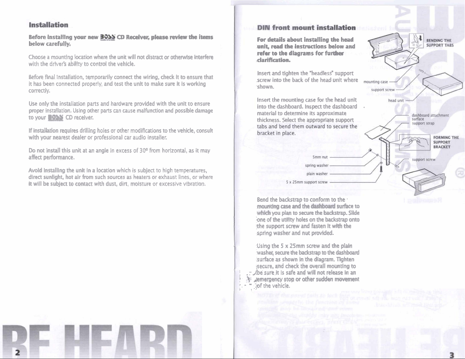
For
details
unit,
mad
ehe
refw
to
the
.clarificatiull.
Insen
and
tlgkten
screw
into
the
.shown.
Insert
the
mounting
into
the
dashboard.
material
thickness.
to
determine its
Select
about
insmnig
lnstruaions
dhgrams
the
*headless
back
of
case
Impect
the
appropriate
the
below
for
fu~
*
the
head
unit
for
the
head
the
dashboard
approximate
head
and
support
where
unit
.
support
lflnstalhtlon
with
your
Do
not
affect
AvoY
direct
%
will
requlres
nearest
kstall
performance.
Installing
puntight,
be
subject
this
the
hot
drlllltlg
dealer
unit
unit
air
to
contact
holes
or
professional
at
an
angle
In
a
location
from
such
with
or
other
In
excess
which
sources
dust,
dirt,
modiflca1ons
car
audlo
Installer.
of
30°
from
is
subject
as
heaters
moisture
to
the
horizontal,
to
hlgh
or
exhaust
or
excessive
vehicle,
consult
as
it
may
temperatures,
lines,
or
where
vibration.
I
,
:
138
&mergsncy
!
?.
-
.;of
1
Bend
the
m~tktg
you
'he
of
the
*he
suppolt
spring
washer
Using
the
washer,
surface
secure,
wre
the
vehkln.
backrap w conform
case
and
the
plan
to
secure
the
utllty
holes
on
the
screw
and
fasten
and
nut
provided.
5
x
25mm
screw
and
seame
he
as
shown
and
deck
It
IS
safe
stop
backtrap
h
the
and
or
other
the
diagram.
werall
wlll
to
not
sudden
to the.
surface
hkstnp.
backstrap
It
wlth
the
the
plain
the
dashbmd
Tighten
mounting
release
In
movement
to
Slide
onto
to
an
Page 4

%kt
a
where
bracket
on
sides
NO
such
psltlon
the
allgn
af
screw
with
the
katlms
on
the
holes
the
head
on
head
of
the
threaded
unit.
Insert
Badl
side,
unit
houshg
factory
screw
screws
and
hdio
holes
in
tighten
securely.
NOTE:
domtusstkvim~b~ckswapor
-nthtll~~.
Before
button
For
the
removing
to
slide
rsamwoum
the
bezel,
down
the
front
?mtsIlptl~lf,
press
the
panel.
OPEN
.
'
.
.
.,..
,
I_
M&6$mMBWrbollron
eskkpfw-
:
I
I
Press
the
OPW
button
to
slide
down
the
front
qalel.
Depress
Srontpartelandpultowarddwfrwar~release
,the
its
for
panel
)he
tht
button
panel,
and carefully pull
bracket.
safekeeping,
In
the
pmrectiw
head
wit.
on
the
underside
the
.
.
immediately
case
ruprlied
panel
place
. .
the
of
the
from
front
wlth
Insert
your
right
side
b&ilg
-,
4
b
kher
iemovTig
OPEN
button
%n,
IW~~~IEWS
unlt
into
unft
as
shown
a
'rHck*
the
un4t
f
fingers
or
the
'.
.-
&e
to
the
groows
In
You
can
'bm
the
into
the
proow
left
side
ofthe
I
slide
up
the
~U~~WWMW'M
(#I
hth
the
drawing
now
uss the
dashbawd.
along the
frame
front
pane&.
sides
of
until
you
hrs
to
hat
the
feel
pull
;
Wh
the
panel
bracket
in
rhe
the
"slkk
downC
~w~~wkwsrt)w8ompd
I
wifw
.
bra&&.
ittm
Press
the
frernt
OFEN
pel
w
Ahfe'th
Into
panel
Pha
'.
pand
up.
-
When
the
panat
-
.
l~~ll~akLd
.+&
VIJ
I.
.,!
$ne
-*him,
slde
of
and
the
push
bracket
front
panel
tha
,her
has
sltd
into
slde
up,
Its
of
Insert
proper
the
panel
-
Page 5

Page 6

:-
Ill:.
;
--
Page 7

Page 8

 Loading...