

Boss RV-500 Owner’s Manual
Owner’s Manual
5 Thanks to 32-bit high-precision processing at a 96 kHz sampling rate from input to output, the
RV-500 gives you stunningly high-quality reverb.
5 With an easily readable screen and an independent [TAP/CTL] switch, it delivers both high
functionality as well as ease of use during live performances.
5 A total of 12 types of reverb are provided, including classic varieties as well as “DUAL” which lets
you use two reverbs simultaneously, the sparkling “SHIMMER,” and models such as “Roland SPACE
ECHO RE-201” and “Roland DIGITAL REVERB SRV-2000.” Powerful DSP lets you use delay and
modulation simultaneously for all reverbs.
5 The memory function lets you store and recall 297 dierent setups from internal memory.
“CARRYOVER” provides seamless transition that preserves the reverberant sound when switching
between patches.
5 By connecting the RV-500 via a USB cable or MIDI cables, you can switch sounds and control
parameters in synchronization with your computer DAW or an external MIDI device.
Getting Ready . . . . . . . . . . . . . . . . . . . . . . . . . . . 2
Installing the Batteries . . . . . . . . . . . . . . . . . . 2
Connecting the Equipment. . . . . . . . . . . . . . . 2
Basic Operation . . . . . . . . . . . . . . . . . . . . . . . . . 4
Adjusting the Reverb . . . . . . . . . . . . . . . . . . . 4
Adjusting the Delay . . . . . . . . . . . . . . . 5
Turning Reverb On/O . . . . . . . . . . . . . . . . . . 6
Switching Banks/Patches . . . . . . . . . . . . . . . . 7
Using the [TAP/CTL] Switch to Control the
. . . . . . . . . . . . . . . . . . . . . . . . . . . . . 8
Reverb
Editing a Patch . . . . . . . . . . . . . . . . . . . . . . . . . . 9
Saving a Patch . . . . . . . . . . . . . . . . . . . . . . . . . . 10
Parameter List . . . . . . . . . . . . . . . . . . . . . . . . . . 11
PATC H . . . . . . . . . . . . . . . . . . . . . . . . . . . . . . 11
Parameters Common to All Modes . . . . 11
Parameters for Each Mode . . . . . . . . . . 12
CONTROL . . . . . . . . . . . . . . . . . . . . . . . . . . . 16
ASSIGN . . . . . . . . . . . . . . . . . . . . . . . . . . . . . 16
BANK . . . . . . . . . . . . . . . . . . . . . . . . . . . . . . 18
SYSTEM . . . . . . . . . . . . . . . . . . . . . . . . . . . . . 18
MIDI . . . . . . . . . . . . . . . . . . . . . . . . . . . . . . . 18
MIDI PC MAP . . . . . . . . . . . . . . . . . . . . . . . . . 19
Before using this unit, carefully read “USING THE UNIT SAFELY” and “IMPORTANT NOTES” (leaet “USING THE UNIT SAFELY ” and Owner ’s Manual
(p. 28)). After reading, keep the document(s) including those sections where it will be available for immediate reference.
© 2017 Roland Corporation
Convenient Functions . . . . . . . . . . . . . . . . . . . . 20
Specifying Whether to Carry-Over the Reverb
. . . . . . . . . . . . . . . . . . . . . . . . . . . . . . 20
Sound
Assigning the Functions of the [A], [B], and
[TAP/CTL] Switches
Using Two Patches Simultaneously
(Simul Mode)
Assigning a Function to an External Pedal. . . . . 22
Synchronizing with a DAW or External MIDI
Device
. . . . . . . . . . . . . . . . . . . . . . . . . . . . . . . . . 24
Connection Example . . . . . . . . . . . . . . . . . . . 24
MIDI Messages That Can Be Transmitted and
Received
MIDI Routing . . . . . . . . . . . . . . . . . . . . . . . . . 25
Restoring the Factory Default Settings . . . . . . . 26
Transmitting Data to an External MIDI Device . . 26
Troubleshooting . . . . . . . . . . . . . . . . . . . . . . . . . 27
Main Specications . . . . . . . . . . . . . . . . . . . . . . 27
USING THE UNIT SAFELY . . . . . . . . . . . . . . . . . . . 28
IMPORTANT NOTES . . . . . . . . . . . . . . . . . . . . . . 28
. . . . . . . . . . . . . . . . . . . . 20
. . . . . . . . . . . . . . . . . . . 21
. . . . . . . . . . . . . . . . . . . . . . . . . . . . 24
Getting Ready
Installing the Batteries
Install four alkaline batteries (AA, LR6) in the battery compartment located on the bottom of the
unit.
* When turning the unit over, be careful so as to protect the buttons and knobs from damage.
Also, handle the unit carefully; do not drop it.
* If you handle batteries improperly, you risk explosion and uid leakage. Make sure that you
carefully observe all of the items related to batteries that are listed in “USING THE UNIT SAFELY”
and “IMPORTANT NOTES” (separate sheet “USING THE UNIT SAFELY” and Owner’s manual (p. 28)).
* We recommend that you keep batteries installed in the unit even though you’ll be powering it
with the AC adaptor. That way, you’ll be able to continue a performance even if the cord of the
AC adaptor gets accidently disconnected from the unit.
* “BATTERY LOW” will appear on the display if the batteries are low. Replace them with new ones.
Attaching the Rubber Feet
You can attach the rubber feet (included) if necessary.
Attach them in the locations shown in the illustration.
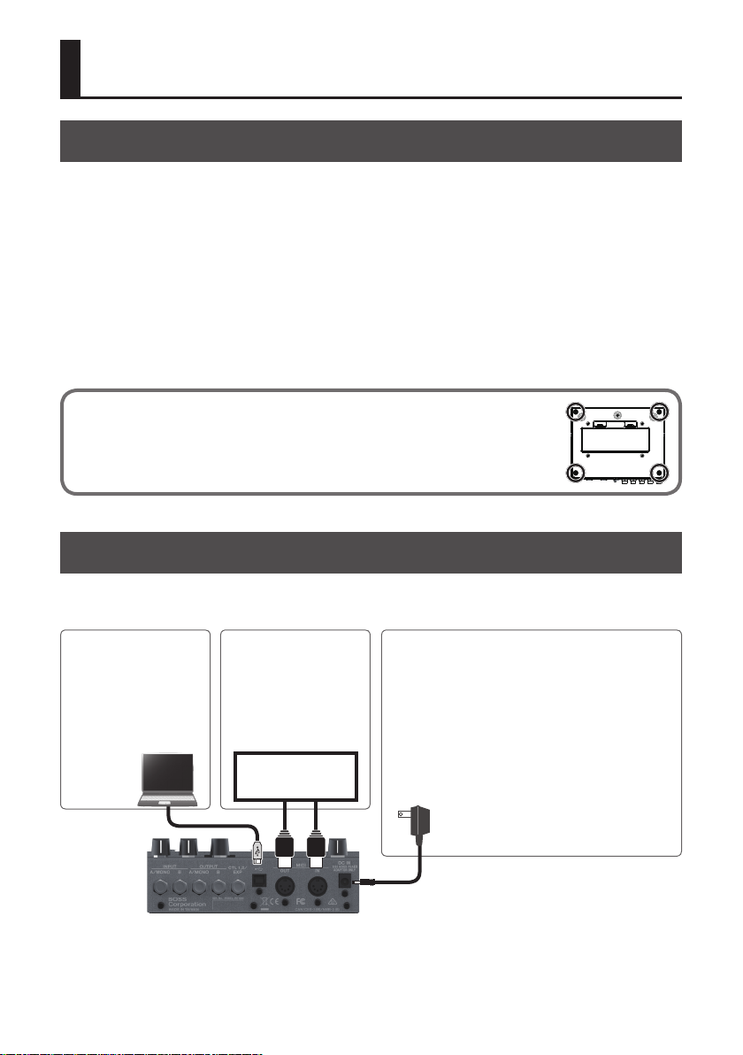
Connecting the Equipment
* To prevent malfunction and equipment failure, always turn down the volume, and turn o all
the units before making any connections.
USB (O) port
Use a commercially available
USB 2.0 cable to connect this
port to your computer.
You can synchronize with a
DAW via MIDI.
MIDI IN, OUT connectors
Connect an external MIDI
device here.
You can synchronize with
an external MIDI device
via MIDI.
MIDI device
DC IN jack
Accepts connection of an AC Adaptor (PSA-S series; sold
separately). By using an AC Adaptor, you can play without
being concerned about how much battery power you have left.
* Use only the specied AC adaptor (PSA-S series; sold
separately), and connect it to an AC outlet of the correct
voltage. Do not use any other AC adaptor, since this may
cause malfunction.
* If the AC adaptor is connected while power is on, the power
supply is drawn from the AC adaptor.
2
Getting Ready
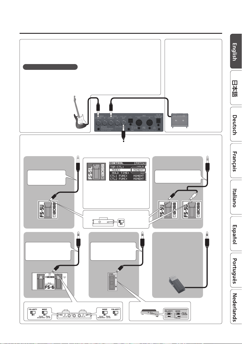
INPUT A/MONO, B jacks
Connect your electric guitar, or another instrument or eect unit, to these jacks.
* Use the INPUT A/MONO jack and B jack when connecting a stereo-output eects unit. Use
only the INPUT A/MONO jack if you’re using a mono source.
Turning the power on/o
The INPUT A/MONO jack doubles as the power switch. Power to the unit is turned on when
you plug into the INPUT A/MONO jack; the power is turned o when the cable is unplugged.
When powering up:
Turn on the power to your amp last.
When powering down:
Turn o the power to your amp
rst.
CTL 1, 2/EXP jack
You can control various parameters by connecting a footswitch (FS-5U, FS-5L, FS-6, FS-7: sold separately) or an expression pedal (such as
the EV-30, Roland EV-5: sold separately) to the CTL 1, 2/EXP jack (p. 22).
When Connecting an FS-5U
(or FS-5L)
1/4” phone type ,1/4”
phone type
When connecting an FS-5L, set MODE to
“MOMENT” (p. 22).
OUTPUT A/MONO, B jacks
Connect these jacks to your amp
or monitor speakers.
If you’re using a mono setup, use
only the OUTPUT A/MONO jack.
* Do not connect headphones to
the OUTPUT A/MONO, B jacks.
Doing so may damage the
headphones.
When Connecting Two FS-5Us
(or FS-5Ls)
Stereo 1/4” phone type
,
1/4” phone type x 2
POLARITY switch
CTL 1 CTL 2 CTL 1
When connecting expression
pedal
* Use only the specied
Stereo 1/4” phone type
,
Stereo 1/4” phone type
CTL 2 CTL 1
MODE/POLARITY switch
When Connecting an FS-7When Connecting an FS-6
Stereo 1/4” phone type
,
Stereo 1/4” phone type
MODE/POLARITY switch
expression pedal (EV-30,
Roland EV-5; sold separately).
By connecting any other
expression pedals, you risk
causing malfunction and/or
damage to the unit.
EXP
3
Basic Operation
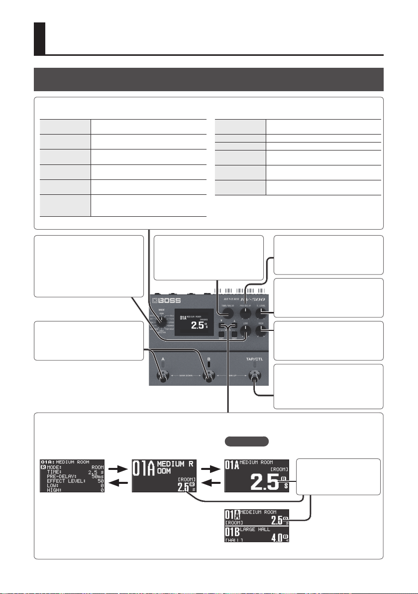
Adjusting the Reverb
[MODE] knob
Selects the type of reverb.
ROOM
HALL
PLATE
SPRING
SHIMMER
FAST DECAY
Reverb that simulates the reverberation in
a room.
Reverb that simulates the reverberation in a
concert hall.
Reverb that simulates plate reverb (a reverb
unit utilizing the vibration of a metal plate).
Reverb that simulates the spring reverb unit
built into some guitar amps.
Reverb with a distinctively brilliant high
frequency range.
Reverb with a fast decay that won't obstruct
your performance even if the eect is applied
deeply.
EARLY
REFLECTION
NON-LINEAR Gated reverb or reverse reverb.
SFX Reverb with a distinctive eect.
DUAL
SRV
SPACE ECHO
Reverb that extracts only the early
reections.
Reverb that lets you use two types of reverb
simultaneously.
Reverb that modelings the Roland SRV-2000
digital reverb.
Reverb that modelings the Roland RE-201
Space Echo.
[LOW] knob
Adjusts the character of the eect
sound’s low-frequency range.
[A] [B] switches
Switch banks/patches (p. 7).
[I] [H] buttons
Switch screens.
[H]
[I]
[TIME/VALUE] knob
Adjusts the reverb time.
To make larger changes in the value,
turn the knob while pressing it.
Top screen
Reverb timeReverb time
[H]
[I]
[PRE-DELAY] knob
Adjusts the time until when the reverb
sound is output.
[E. LEVEL] knob
Adjusts the volume of the eect sound.
[HIGH] knob
Adjusts the character of the eect
sound’s high-frequency range.
[TAP/CTL] switch
Press this switch to change how the
reverb is applied (p. 8).
Turn the [TIME/VALUE] knob
to adjust the value.
In simul mode (p. 21)
4
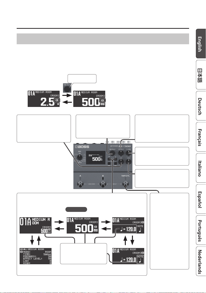
Adjusting the Delay
The RV-500 lets you use reverb and delay simultaneously.
Each time you press the [TIME/VALUE] knob, you alternate between adjusting the reverb and
adjusting the delay.
* To use delay, use CONNECTION to specify how delay is connected (p. 11). If CONNECTION is
turned “OFF,” the delay is o.
Press to switch
DelayReverb
Basic Operation
[LOW] knob
Adjusts the character of the delay
sound’s low-frequency range.
[I] [H] buttons
Switch screens.
[H]
[I]
[H] [I]
[TIME/VALUE] knob
Adjusts the delay time.
To make larger changes in the value,
turn the knob while pressing it.
Top screen
Delay timeDelay time
Turn the [TIME/VALUE] knob to
adjust the value.
[H]
[I]
Tempo
[PRE-DELAY] knob
Adjusts the feedback level (or how
much the sound is repeated).
[E. LEVEL] knob
Adjusts the volume of the eect sound.
[HIGH] knob
Adjusts the character of the delay
sound’s high-frequency range.
[TAP/CTL] switch
You can easily set the delay
time to match the tempo
of the song being played
by pressing the pedal
in time with the song’s
tempo (Tap Input) (p. 8).
[H] [I]
Note length relative to the tempo
Delay time
5
Basic Operation
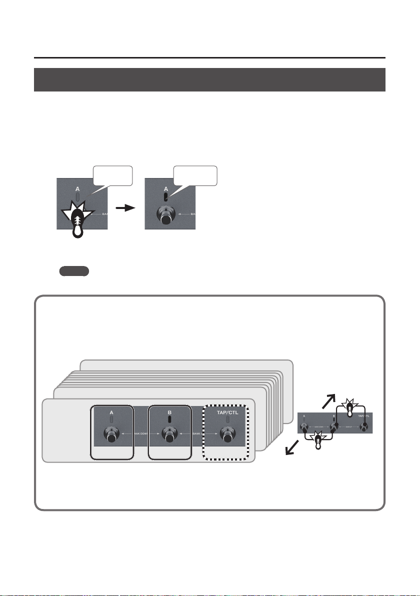
Turning Reverb On/O
Patch A reverb
Each time you press the [A] switch, the reverb alternately turns on (lit blue) / o (unlit).
Patch B reverb
Each time you press the [B] switch, the reverb alternately turns on (lit blue) / o (unlit).
Blue: on Unlit: o
Press once
MEMO
You can also make settings so that patches A and B are used simultaneously (p. 20).
Patches and Banks
Settings for MODE, PRE-DELAY, EFFECT LEVEL, LOW, HIGH, and TIME are collectively called a
“patch.” You can select patches using [A], [B], and [TAP/CTL] switches (p. 20). A combination of
patches A, B, and C is called a “bank.”
BANK 99
BANK 02
BANK 01
Patch 01A Patch 01B Patch 01C
* If you want to use the [TAP/CTL] switch to select patch C, refer to “Assigning the Functions of the [A], [B], and [TAP/CTL]
Switches” (p. 20).
Bank down
6
Bank up
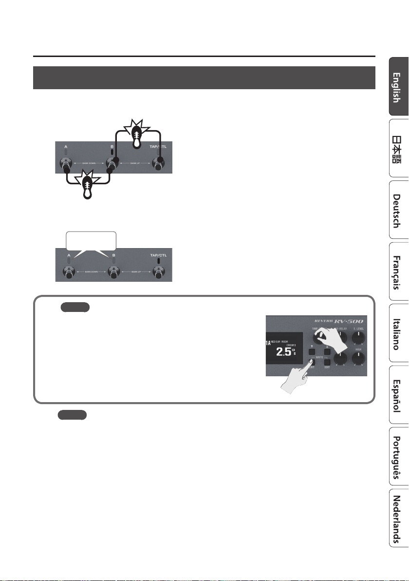
Switching Banks/Patches
Basic Operation
1. Switch banks (01–99).
Bank up (press the [B] and [TAP/CTL] switches simultaneously)
Bank down (press the [A] and [B] switches simultaneously)
2. Press a blinking switch ([A] or [B]) to switch patches.
Blinking blue
MEMO
You can recall a dierent patch by turning the [TIME/VALUE]
knob while you hold down the [EXIT] button.
MEMO
5 You can specify whether the reverb sound is or is not retained when switching patches
(p. 20).
5 You can change the functions that are controlled by the [A], [B], and [TAP/CTL] switches; for
example, you can make the [A] switch turn reverb on/o.
7
Basic Operation
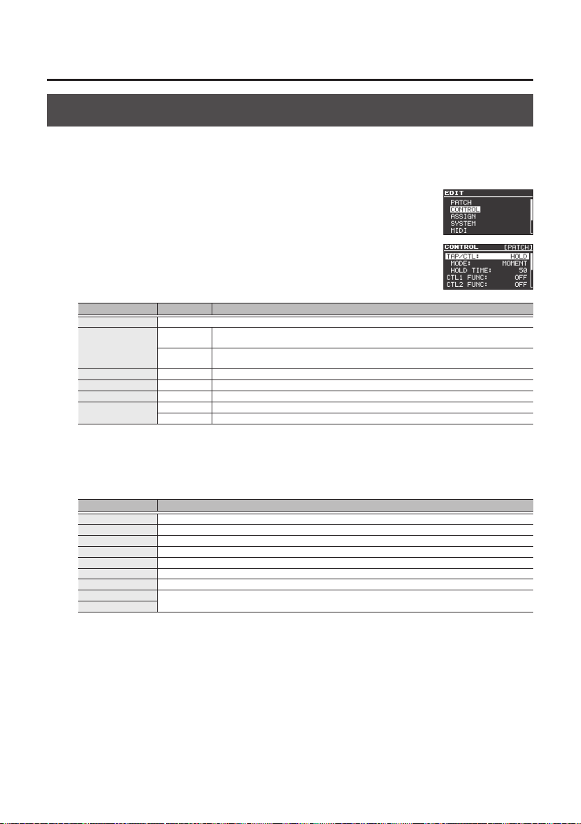
Using the [TAP/CTL] Switch to Control the Reverb
With the initial settings, the [TAP/CTL] switch holds the reverb sound (HOLD); however, you can
change this assignment so that the switch varies the way in which reverb is applied.
1. Press the [EDIT] button.
2. Use the [
H
] [I] buttons to select “CONTROL” and then press the
[EDIT] button.
3. Use the [
H
] [I] buttons to select a parameter, and use the [TIME/
VALUE] knob to edit the value.
Parameter Value Explanation
TAP/CTL Species the function of the [TAP/CTL] switch.
TAP/CTL MODE (*1)
HOLD TIME (*2) 0–100 Species the time over which the input sound plays back repeatedly.
RISE TIME (*3) 0–100 Species the time over which the twist eect rises.
FALL TIME (*3) 0–100 Species the time over which the twist eect falls.
TAP/CTL PREF
*1: This is shown if TAP/C TL is set to “HOLD,” “TWIST,” or “WARP.”
*2: This is shown if TAP/C TL is set to “HOLD.”
*3: This is shown if TAP/C TL is set to “T WIST.”
MOMENT
TOGGLE
PATC H Dierent settings can be made for each patch.
SYSTEM The same settings are shared by all patches.
The switch is normally o (minimum value), and turns on (maximum value) only while you
hold it down.
The switch alternately switches o (minimum value) and on (maximum value) each time
you press it.
TAP/CTL Settings
Value Explanation
OFF No assignment.
HOLD The input sound plays back repeatedly while you hold down the switch.
WARP Simultaneously controls the reverb sound’s feedback level and volume to produce a totally unreal reverb.
TWIST A new type of reverb that produces an aggressive, spinning sensation.
TAP Lets you specify the delay time by tap input.
MOMENT Outputs the reverb sound only while you hold down the switch.
FADE Fades-in/-out the input sound.
BANK UP
BANK DOWN
Change banks.
4. Press the [EXIT] button to return to the top screen.
8
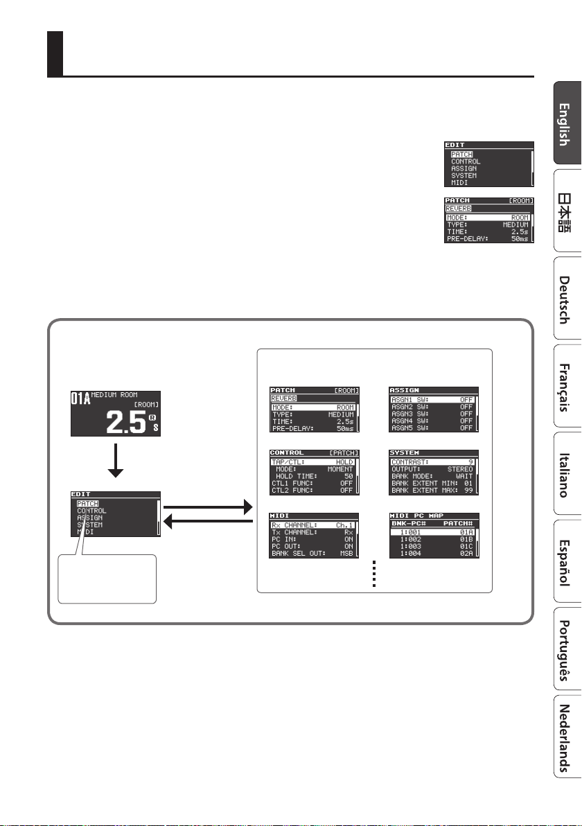
Editing a Patch
You can edit a variety of patch-related parameters.
1. Press the [EDIT] button.
2. Use the [
[EDIT] button.
3. Use the [
VALUE] knob to edit the value.
H
] [I] buttons to select “PATCH,” and then press the
H
] [I] buttons to select a parameter, and use the [TIME/
4. Press the [EXIT] button to return to the top screen.
* Save the edited patch as described in the procedure on “Saving a Patch” (p. 10).
Basic [EDIT] operations
Use the [H] [I] buttons to move the cursor
Use the [TIME/VALUE] knob to edit the value
[EDIT] button
[EDIT] button
[EXIT] button
Use the [H] [I] buttons
to move the cursor
9
 Loading...