

Page 1

RPD-10
pnnninc DEUV
INSTRUCTIONS
Please read the instructions carefully.
Page 2

FEATURES
The BOSS RPD-10 is a completely new type machine
that can create a panning delay effect which was only
possible by using two delay machines.
• This unit can create as long as two second delay
time. ^ The best possible panning effect can be
obtained.
• This unit features Chorus mode. It can be used
as a stereo chorus effect.
• The Direct Cancel Switch is provided. The unit
can send only effect sounds to a mixer.
• This unit features the Input Level Selector Switich
and both a standard phone jack and a pin jack for
input. Not only a musical instrument but also
audio equipment can be used with this unit.
• Using the optional adaptor RAD-10, this unit can be
mounted on a standard 19" rack (EIA).
CONTENTS
'Warning - Thii equipment he« b«en vended to comply with the limitt for a 6 computir^g device,
pursuant (p SuOpert J, of Part 15. of PCC rules. Operation with rkon^ert^ried or non-verrfieq equip
ment IS iiketY to result m *nterference to radio ar>d TV reception/
The equipment des<rit>e<f in thts manual generates and uses redio-frequer^ energy, if *t is noi
installed and used property, tha\ is, in strict eccordarKe with our instructions, n may cause interfer
ence With radio end television reception.
This equipment has been tested artd found to com ply with the limits for a Cfass 6 computing
device in accordance with the specifications in Subpari j, of Part 1^. of FCC fiuies. These rules are
designed io provide reasonable protection against such a »nterfarence in a rasidemial installation.
However, there >s no guarentee that the interference win not occur in a particular installation, if this
equipment does cause interference to radio or tatavision reception, which can be determined by turning
the equipment on and off, the user rs encouraged to try to correct the »ntarferertce by the
following meesure:
e Disconnect other devices and their mput'^output cables one at a time, if the interference stops, it
*s caused by anhar the other device or its irO cable.
These davices usualty require Aoiand designated shielded HO cables. For floiand devices, you can
obtain the proper shielded cable from your dealer. For non Roland cfevices, contact the manufeciurar
or dealer for aisiiiartce.
If your equipment does cause interfarence to radio or taiavision reception, you can try to correct
the miorference bv usmg one or more of the foiTowing maasures:
• Turn the TV or radio antenna until the mterferer>ces stops.
• hiqya the equipment to one side or the other of the TV or radio,
• Move the equipment farther away from the TV or radio.
Plug the equipment into an outlet that *s on a different circuit than the TV or radio. (Thai is, make
certain the equipment and the radio i
breakers or fuses.)
Consider installing a rooftop leiev
TV,
If necessary, you should consuTt your deater or an experieisced radiO'^teiav^siorv technician for
additional suogtstions. Vou may fmd helpful ff^ following booklet prepared by tha Federal Communications vommision:
"Hovr to identify and Resolve ftadio*TV interference Probtems'
This booklet is available from the t>.$. Covernmant Printing Office, Washington, D.C, 2040?,
Stock hro. 004 000-0034S.4.
RADIO AND TELEVISION INTERFERENCE
r tsfayision set are on circuits controlled by different <
antenna with coaxial саЫе faad-m batweti and
Bescheinigung des Herstellers/Importeurs
Hiermit wird bescheinigt, daß der/die/das
• BOSS DIGITAL PANNING DELAY RPD-10
tGe.'Si typ Bcrrhcrwxjnq)
in Übereinstimmung mit den Bestimmungen der
<AmTsO£auviMlugung)
Amtsbl, Vfg 1046/ 1984
[H Panel Description
..................................................
Connection ...........................................................6
O Operation.................................................................7
[4] Setting Samples
..................................................
8
[D Setting Memo ...................................................... 9
[S Important Notes .................................................. 10
S Specifications........................................................ 11
3
funk-enstort ist.
Der Deutschen Bundespost wurde das Inverkehrbringen dieses Gerätes
angezeigt und die Berechtigung zur Überprüfung der Serie auf Einhaltung der
Bestimmungen eingeräumt,
Roland Corporation Osaka/Japan
NA’vy o«. iniponeu'S
Page 3
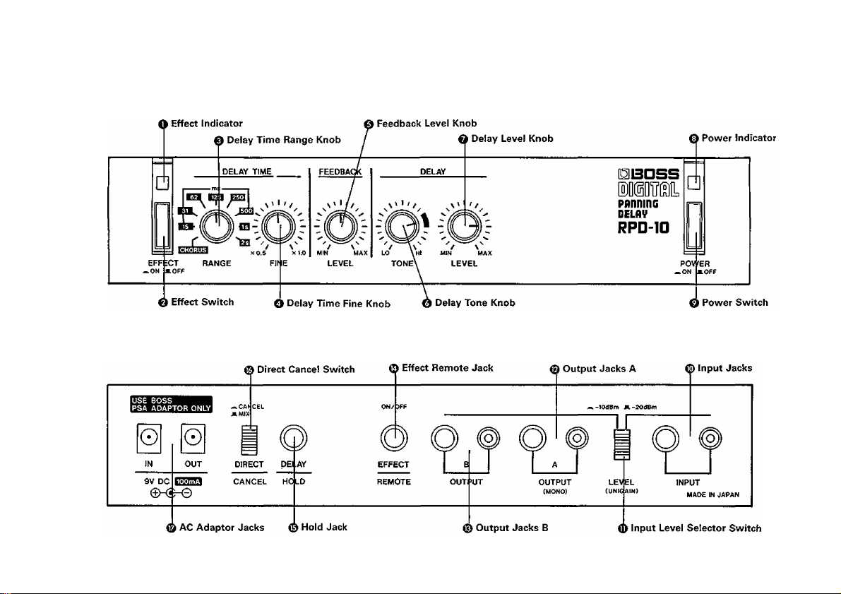
[T] PANEL DESCRIPTION
Page 4

O Effect Indicator
This lights up when the effect is turned on.
O Effect Switch
This turns on or off the effect.
0 Delay Time Range Knob
This selects one of the 8 delay time ranges (15ms
to 2s).
* When you change delay time range from "2s" to
any other one or from any range to "2s", muting
circuits are activated, therefore no delay sound is
heard for a few seconds.
When "CHORUS" position is selected, the unit is
turned to Chorus mode, behaving like a stereo chorus.
O Delay Time Fine Knob
This knob can finely adjust the delay time range set
with the Delay Time Range Knob. The set delay time
can be continuously changed from "xO.5" to "x1".
* Using the Delay Time Range Knob and the Delay
Time Fine Knob, delay time can be set from 7.5 ms
to 2s continuously.
When the Chorus mode is selected, this knob adjusts
the depth of the chorus effect.
0 Feedback Level Knob
This sets the number of the delay repeats. Clockwise
rotation increases the number of the repeats, and at
its fully counterclockwise position, a single delay (one
delay for each right and left each in stereo) will be
created.
* When this knob is set fully clockwise, oscillation
may occur. If so, rotate the knob counterclockwise
until the oscillation stops.
* This knob does not work in the Chorus mode.
O Delay Tone Knob
This adjusts the tone of the delay (or chorus) sound.
Rotating the knob counterclockwise cuts higher fre
quencies, creating softer sound. At 3 o'clock position,
almost flat characteristic is obtained.
0 Delay Level Knob
This controls the volume of the delay (or chorus)
sound. Clockwise rotation raises the volume.
0 Power Inidcator
This lights up when the unit is turned on.
O Power Switch
0 Input Jack
Connect a musical instrument or audio equipment to
this jack.
* The standard and the pin jacks cannot be used at
the same time. When both are used simultaneously,
the standard phone jack will work.
0 Input Level Selector Switch
Set this switch depending on the output level of the
connected device.
* When a musical instrument is connected, set the
switch to "-20dBm", and when an AV equipment
is connected, set it to "-lOdBm". When sounds
are distorted at "-20dBm" position, set it to
" —lOdBm".
Page 5

* Changing this switch does not affect the volume
of the sound.
0 Ouput Jacks A
Connect this jack to a device such as guitar amplifier,
stereo amplifier or tape deck. (Both the standard and
pin jacks can be simultaneously used.)
* Use this jack for monaural use.
® Output Jacks B
By using this jack together with the Output Jack A
in stereo, panning effect can be obtained. (Both the
standard and pin jacks can be simultaneously used.)
Effect Remote Jack
By connecting a footswitch FS-5L (optional) to this
jack, Normal/Effect mode can be selected using the
pedal.
* Make sure that the Effect Switch on the panel is
turned on.
When using two sets of the BOSS Micro Studio Series,
it may be a good idea to connect the Effect Remote
Jack of one unit to another one, so that you can turn
on or off the effects of both units simultaneously by
operating one unit.
Hold Jack
This jack is to connect the FS-5U (optional footswitch).
As long as the footswitch is depressed, the input sound
will be repeated.
* The Hold effect cannot be obtained when the unit is
in the normal mode (=effect is off)
Direct Cancel Switch
When this switch is turned on, direct sound is cut,
only the delay (or chorus) sound being sent out. This is
useful for effect-loop use of a mixer.
AC Adaptor Jacks
The "IN" jack is to connect the AC adaptor (BOSS
PSA-120, 220 or 240) or the Power Supply (BOSS
RPW-7). Connect the plug of the AC adaptor or the
Power Supply to "IN". To supply power to other
BOSS Micro Studio Series, connect the supplied DC
cord to "OUT".
* When using the PSA-Adaptor, be sure the total
current draw does not exceed 200mA, and when
using the RPW-7, 700mA. (The current draw of
each unit is shown on its rear panel.)
Page 6

Page 7

\E OPERATION
(X) Set the controls on the panel as shown below.
Using the unit as a delay machine
DELAY TIME
/ \
RANGE FINE
Using the unit as a chorus machine
Set the Effect Switch to the OFF position.
Set the Direct Cancel Switch on the rear panel to
the MIX position except when a mixer {effect loop)
is used.
X0.5 xl.o
DELAY
i,Q? IQ;
V' ' '/
/ \
^ y
TONE
(3) Set the Input Level Selector Switch to either posi
tion depending on the output level of the device.
® Turn the Effect Switch on {the Effect Indicator
lights up), and delay (or chorus) effect is obtained.
(5) Using the controls on the panel, make a desired
sound. (See page4.)
C> By connecting an optional footswitch (FS-1, FS-5L
etc) to the Effect Remote Jack, the effect can be
turned on or off by pressing the pedal.
* Be sure that the Effect Switch on the panel is
turned on.
* The RPD-10 can be turned from effect to normal
mode without cutting the delay sound currently
played.
I> By connecting an optional footswitch (FS-5U etc.)
to the Hold Jack, the Hold effect can be obtained
as long as the pedal is depressed. The length of
each repeat is the delay time currently set.
* The Hold effect cannot be obtained when the unit is
in normal mode (=effect is off).
(2) Push the Power Switch and make sure the Power
Indicator lights up.
Page 8

H SETTING SAMPLES
1) Light Chorus
I mtm I
— / \
RAKGE FINE LEVEL TONE LEVEL
X0.5 xtO
mm)
2) Deep Chorus
DELAY TIME
FEEDBACK
x'l'/
X X
&
FINE LEVEL TONE LEVEL
WH MAX
m m
'X'
LO Hi
3) Short Delay
DELAY TIME
x''f/ ^x"'/^
4) Long Delay
_____
DELAY TBWe
0^0^
"Tm
xO.5 X1.0
5} Effect as if played by three persons
FEEDBACK DELAY
V' ■ f/ ^x' •
(&)
FINE LEVEL
* '' y
LO M MM MAX
TONE LEVEL
RANGE FINE LEVEL TONE LEVEL
X 0.5 X VO
m m
8
Page 9

SETTING MEMO
DELAY TIME FEEDBACK DELAY
fi j) ® “ ({( ll) r
_rv_-/
RANGE FINE
xp.$ xtX)
MIN MAX
LEVEL
LO HI Mm MAX
TONE LEVEL
DELAY TIME
l*iii*iiVrl XO.S xtO
RANGE FINE
DELAY TIME
“ Cji ®'Cj '
eia ^>,0'/
RAKGE RNE
FEEDBACK DELAY
'ra
M(N MAX
LEVEL
FEEDBACK
'i s'
MIN MAX
LEVEL
'/ \'' ' t
LO HI MIN MAX
TONE LEVEL
vi 1 / 0 '
LO HI MIN MAX
TONE LEVEL
DELAY
Page 10

IMPORTANT NOTES
AC Adaptor, Power Supply
• For about 10 seconds after the unit is turned on, it
does not function because of the muting circuit.
• When you are using only one AC adaptor {or RPW-7)
for supplying power to more than one unit, please
be sure that the total current draw does not exceed
200mA {or 700mA).
• When the unit is not to be used, disconnect the AC
adaptor from the socket.
• Avoid using the unit in excessive heat or humudity
or where it may be affected by dust or vibration.
• Never remove the cabinet from the unit.
• When you use the unit on its own without using
the optional Rack Mount Adaptor RAD-10, please
attach the rubber feet as shown below.
BOSS PSA-120, 220 or 240 (optional)
BOSS RPW-7 (optional)
Be sure to use the above AC adaptor or power supply.
Using any other adaptor or power supply will cause
trouble.
■ Rack Mounting
The RPD-10 is one of the BOSS Micro Studio Series,
and any two of the series can be mounted in a standard
19" rack (EIA-1U) by using the optional Rack Mount
Adaptor RAD-10.
Remove the rubber feet from the bottom of the units,
fix the units on the Rack Mount Adaptor with the sup
plied screws, then place the whole set on the rack.
10
Page 11

[7] SPECIFICATIONS
Input Level/Input Impedance:
-20dBm/1Ma -10dBm/47kii
Output Level/Output Impedance:
-20dBm/2kn, -10dBm/2kii
Output Load Impedance: Over 10kil
Sampling System:
12 bit quantizing and analog logalithmic
compression system {8 bit when the Delay
Time Range is set to 2s)
Frequency Response:
Direct: 10Hzto60kHz (;|l''3dB}
Delay: 20Hz to 15kHz (llgdB)
Residual Noise:
Below — lOOdBm (IHF-A) when the Input
Level Selector Switch is set to -20dBm
Controls:
Delay Time Range (9 steps)
Delay Time Fine
Feedback Level
Delay Tone
Delay Level
Switches:
Power (ON/OFF)
Effect (ON/OFF)
Input Level Selector (-20dBm/“10dBm)
Direct Cancel (Cancel/Mix)
Inidcators:
Power
Effect
Jacks: Inputs (Standard, Pin)
Outputs A (Standard, Pin)
Outputs B (Standard, Pin)
Effect Remote (ON/OFF)
Hold (ON/OFF)
Power:
9VDC (BOSS PSA-120, 220 or 240, RPW-7)
Current Draw:
100mA
Dimensions:
218(W) X 169(D) X 44(H)mm/
8ys" X 6%" X 13/4"
Weight:
900g/2 lb
Accessories:
DC Cord (0.5m)
Rubber Feet x 4
OPTIONS
AC Adaptor PSA-120, 220 or 240
Power Supply RPW-7
Rack Mount Adaptor RAD-10
Footswitch FS-5L, FS-5U, FS-1 (Roland)
* Specifications are subject to change without notice.
1 1
Page 12

Products of Roland
Printed In Japan Aug. '87 E-3
 Loading...