

Boss MX1-3HL, MX2-3HL Operation & Maintenance Manual
www.bssindustrial.co.uk
We reserve the right to change designs and technical specifications of our products.
Rev 2.1 Oct-15 Page 1 / 28
Rev 2.1
BOSS Mini Mechanical
Pressurisation Equipment
Mini Models (MX1-3HL, MX2-3HL)
Operation & Maintenance
Manual
www.bssindustrial.co.uk
We reserve the right to change designs and technical specifications of our products.
Rev 2.1 Oct-15 Page 2 / 28
Do not use this equipment to fill a system, use a WRAS approved filling loop for initial filling.
Mechanical equipment does not have the required electrical monitoring for ethical system filling
operations. Under no circumstances must mini units be used to fill a system of any size.
A suitable safety relief valve must be fitted to the system.
Customer Details
Please fill in information future reference:
Company: Contact:
Address: Tel No:
Fax No:
Post Code: E-mail:
Equipment Details
Details of model and serial number may be found on the label
Model: Serial No:
Purchase date: Purchase From:
Note:
It is highly recommended to have this equipment commissioned by a BOSS approved engineer. Any damage or
loss incurred through incorrect commissioning by an unapproved engineer will not be covered by the warranty.
If you wish for BOSS to arrange this please contact us. (See contact details)
Please see the warranty section for details.
Remember to fill in details for future use for re-commission unit.
www.bssindustrial.co.uk
We reserve the right to change designs and technical specifications of our products.
Rev 2.1 Oct-15 Page 3 / 28
Site Reference:
PU Reference:
Date Commissioned:
/ /
Engineer Name:
Company:
PUMP CONTROL PRESSURE SWITCH
HIGH/LOW PRESSURE SWITCH
RANGE:
HIGH PRESSURE - CUT OUT
DIFFERENTIAL:
LOW PRESSURE - CUST IN
PUMPS NUMBER:
1 / 2
Delete as
appropriate
LOW PRESSURE - DIFF
NOTES:
Engineer Signature:
Date:
/
/
Customer Signature:
Date:
/
/
Commissioning Record
FILL IN RECORD TO VALIDATE WARRANTY OF PRESSURISATION UNIT
Commissioning certificate can be obtained please contact BSSrepresentative

www.bssindustrial.co.uk
We reserve the right to change designs and technical specifications of our products.
Rev 2.1 Oct-15 Page 4 / 28
Contents
Customer & Equipment details 2
Commission Record 3
About this Manual
Where to find more Information 5
Equipment Overview
Principal of Operation 6
Important Information
Environment 7
Safety 7
Application 7
Cold Pressures 7
Installation
Pipe Connections 8
Typical Installation Diagram 8 - 9
Flow Restrictors 9 - 10
Mini Clearance and Connection Requirements 11
Electrical Power Supply 12
Commissioning
Pre-Commissioning Checklist 13
Commissioning 14 - 16
Hydraulic Commissioning 17 - 18
Maintenance
Maintenance information 19
Wiring
Wiring Diagram 20
Spares
Mini Models (MX1-3HL, MX2-3HL) 21 - 22
Troubleshooting 23
Service Log 24 - 25
Warranty Information 26
www.bssindustrial.co.uk
We reserve the right to change designs and technical specifications of our products.
Rev 2.1 Oct-15 Page 5 / 28
About this Manual
This Operation and Maintenance Manual contains all the necessary information to install, commission, operate
and maintain Flexfiller pressurisation equipment.
It is recommended to read all parts of this manual before undertaking any work on the equipment.
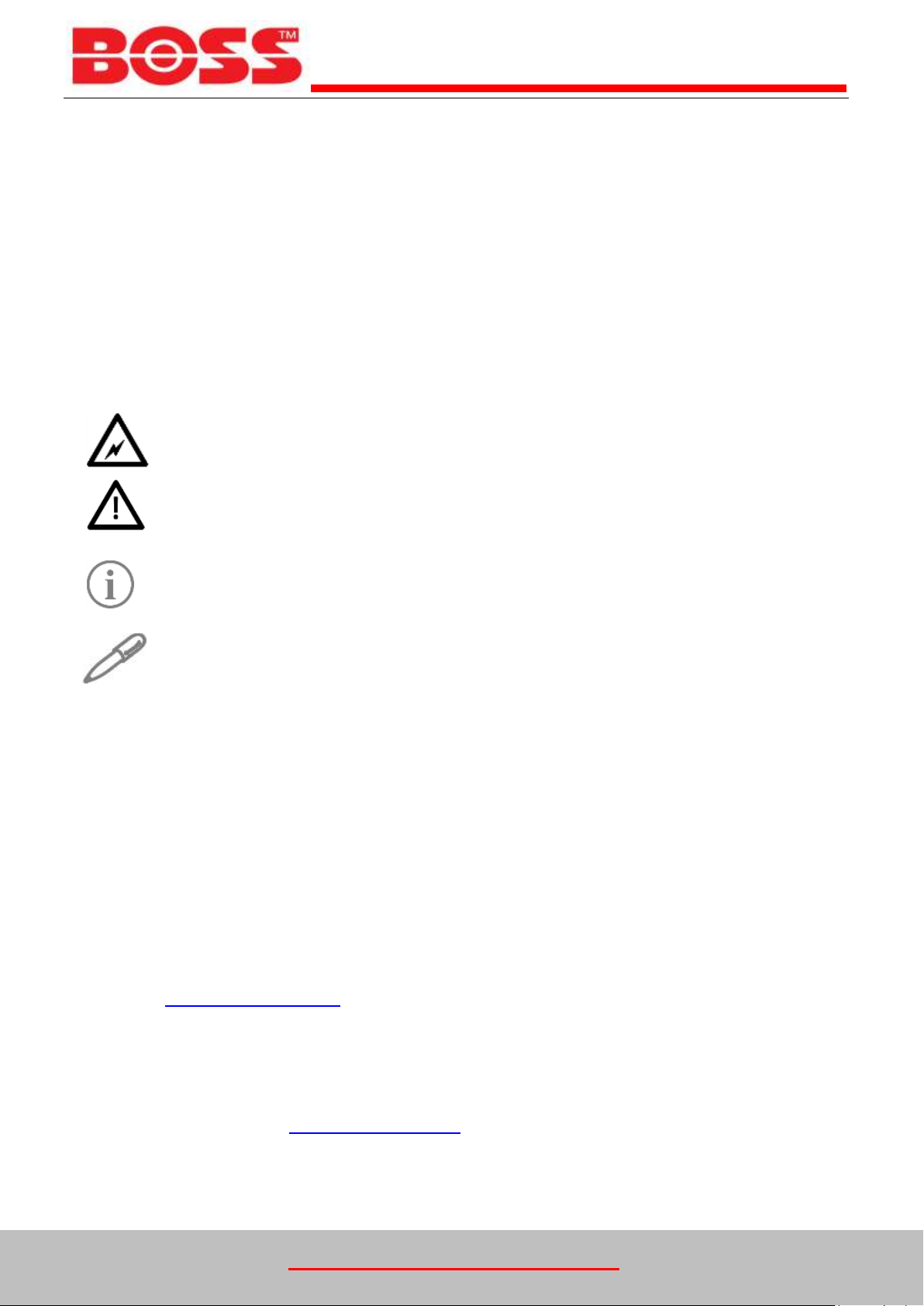
Conventions used in this Manual
This manual makes use of symbols to identify key pieces of information. Please take note of the following
symbols and their meaning:
DANGER – Important safety related information intended to prevent injury and/or damage to the
equipment, system or property.
CAUTION - Important information intended to prevent damage to the equipment, system or
property.
IMPORTANT - Important information intended to ensure that the equipment functions correctly.
USEFUL – Useful information which may be helpful, but is not necessarily required for the unit to
function correctly.
Typography
This manual makes use of different typography to identify different types of information.
Italics Key words and phrases
(Round Brackets) Used to identify a button on the digital controller
[Square Brackets] A parameter on the digital controller
<Inequality Symbols> A message/fault code displayed on the digital controller
Where to find more Information
For further information please visit the BSS Website at the following URL:
www.bssindustrial.co.uk
Alternatively, please contact the BSS technical team using the details below:
Phone: 0116 262 3232
Fax: 0116 253 1343
Email: equiries@bssgroup.com
www.bssindustrial.co.uk
We reserve the right to change designs and technical specifications of our products.
Rev 2.1 Oct-15 Page 6 / 28
Equipment Overview
The function of this pressurisation unit is to provide a means of automated water top-up to sealed heating and
cooling systems. The equipment is designed to provide periodic water top-up to compensate for minor losses in
system pressure (e.g. slow leaks, air venting, etc.).
This equipment is not designed to cope with sudden losses of system pressure (e.g. manual
draining) or major water losses (e.g. large leaks). The equipment is also not intended to be used
for water boosting applications.
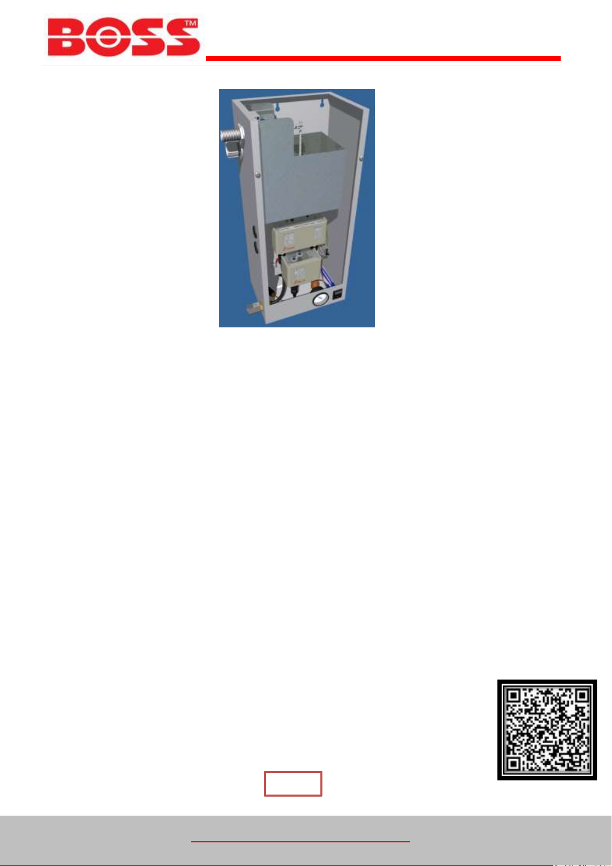
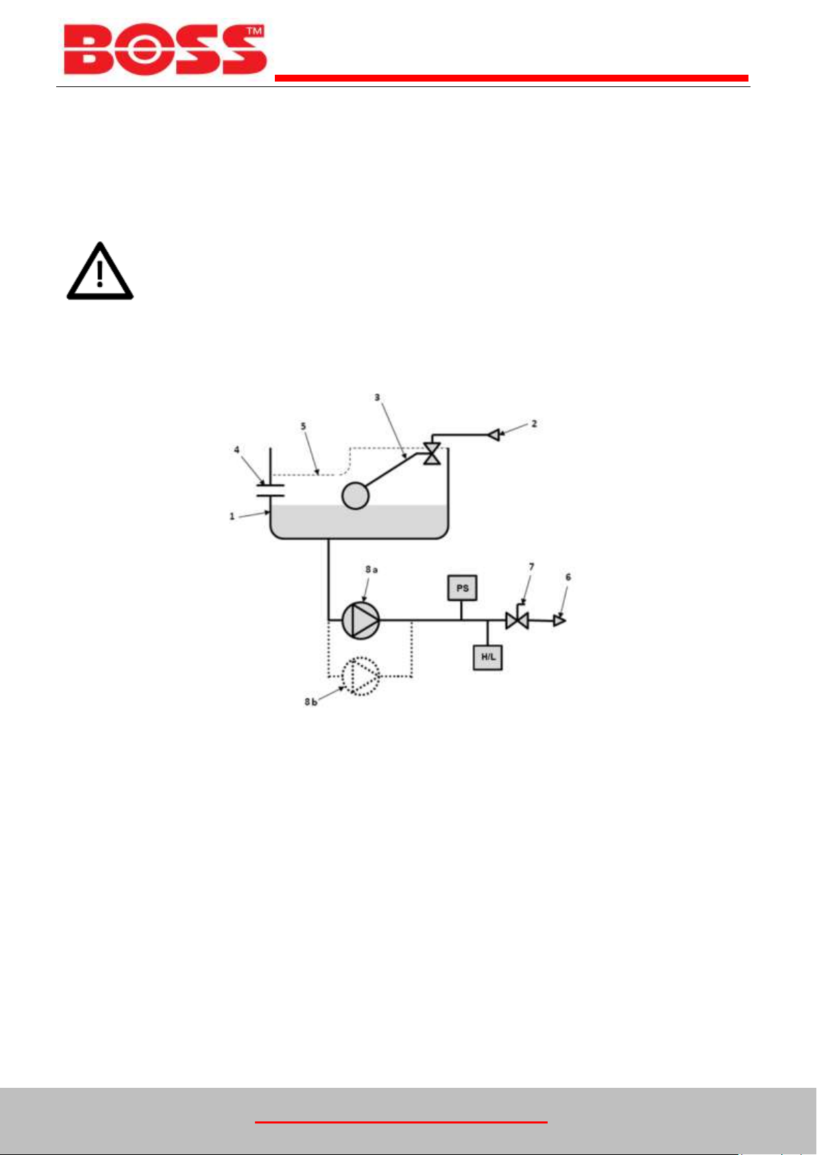
Principal of Operation
The following schematic shows the internal arrangement of a pressurisation unit:
The pressurisation unit is fitted with a break tank (1) which is filled from the mains water supply (2) via a float
operated valve (3). The break tank is fitted with an overflow (4) in case the break tank overfills, and a weir
overflow (5) in case the primary overflow fails.
The pressurisation unit is connected into the heating system (6) via an isolation valve (7).
The pressure switch (PS) monitors the system pressure. High/Low Switch (H/L) is connected to the boiler to
control the cut in and cut out of boiler pressure
If the pressure sensor detects a drop in pressure, the pump (8a or 8b) will pump water from the break tank into
the system. Once the required pressure has been reached, the pump will stop.
On twin pump models, a second pump (8b) is provided. On mechanical unit you can select either pump with a
pump selection switch

www.bssindustrial.co.uk
We reserve the right to change designs and technical specifications of our products.
Rev 2.1 Oct-15 Page 7 / 28
IMPORTANT INFORMATION
Environment
It is not anticipated that this equipment will be exposed to adverse
environmental conditions without additional protection.
Site the equipment in a frost free area.
Ensure that 100 mm of clear access is available around the equipment with 500 mm clear access at the
front.
Flush the mains water supply pipe before connection to this equipment.
An inline filter must be fitted to the inlet of the equipment if the mains water supply is suspected to contain
debris.
Please refer to BS 7074 for the installation code of practice.
Do not use this equipment to fill a system unless otherwise stated; it is designed to ‘top-up’ a system in the
event of pressure loss due to deaerating and minor system leakage.
Safety
Electrical installation must be carried out by a competent person
WARNING – LIVE TERMINALS WITHIN THIS EQUIPMENT
Isolate the equipment before removing any covers
Do Not make any electrical adjustments to the equipment unless it is isolated from the mains electrical
supply
Do Not operate with the electrical covers removed
Do Not alter any internal pipe-work, this equipment is tested prior to Dispatch.
Do Not obstruct and ventilation fans or apertures
Check supply voltage and overload protection is correct
Application
Automatic make up and pressurisation unit for sealed heating and cooling systems.
This equipment is designed to work in conjunction with an appropriately sized expansion vessel.
Cold Pressures
The unit is fully adjustable to provide a minimum static pressure of 0.7 bar(g) the maximum static
pressure is dependent on the pump set fitted. If in any doubt please contact your product supplier.
www.bssindustrial.co.uk
We reserve the right to change designs and technical specifications of our products.
Rev 2.1 Oct-15 Page 8 / 28
Installation
This pressurisation unit is not designed to be installed in an outdoor environment. The unit must
be installed in a frost free environment, away from precipitation and water sprays/jets. If there is
a risk of flooding, the unit must be installed on a raised plinth.
Please refer to the appropriate datasheet for the maximum working pressure and temperature of
the pressurisation unit. The conditions at the point of connection to the system must not exceed
these values.
Pipe Connections
To avoid damaging the float valve, the mains water supply pipe must be flushed before
connection to the pressurisation unit.
All pipe connections must be made with appropriate jointing compound/PTFE tape.
If PTFE tape is used, care must be taken to ensure that the tape does not obstruct the orifice of
the fitting.
Non-return valves, pressure reducing valves and RPZ valves must not be installed between the
pressurisation unit and the heating/cooling system. These devices will prevent the pressure
sensor from reading the system pressure.
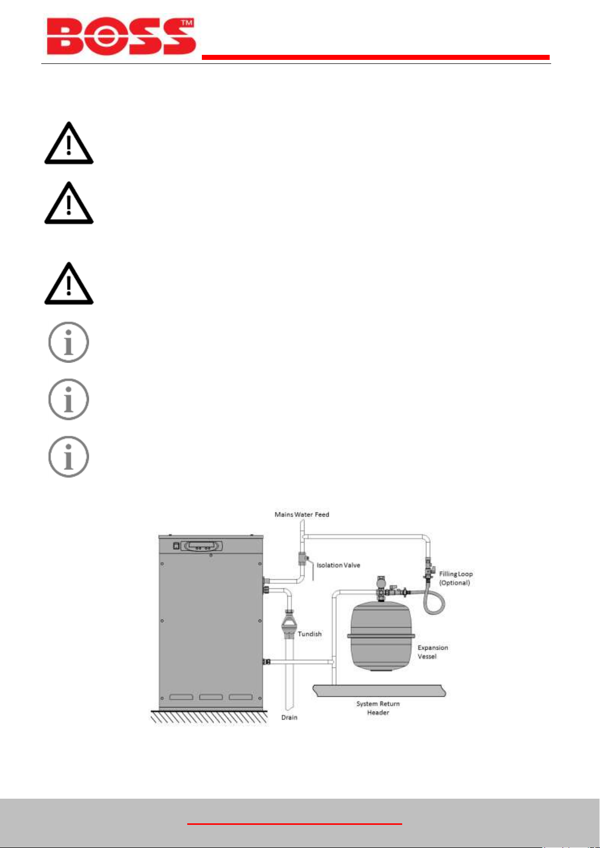
The pressurisation unit and expansion vessel should be connected to the system at the same
point, to provide a neutral pressure reading. This point of connection should be in the system
return, on the suction side of the circulation pump.
Typical Installation Diagram
www.bssindustrial.co.uk
We reserve the right to change designs and technical specifications of our products.
Rev 2.1 Oct-15 Page 9 / 28
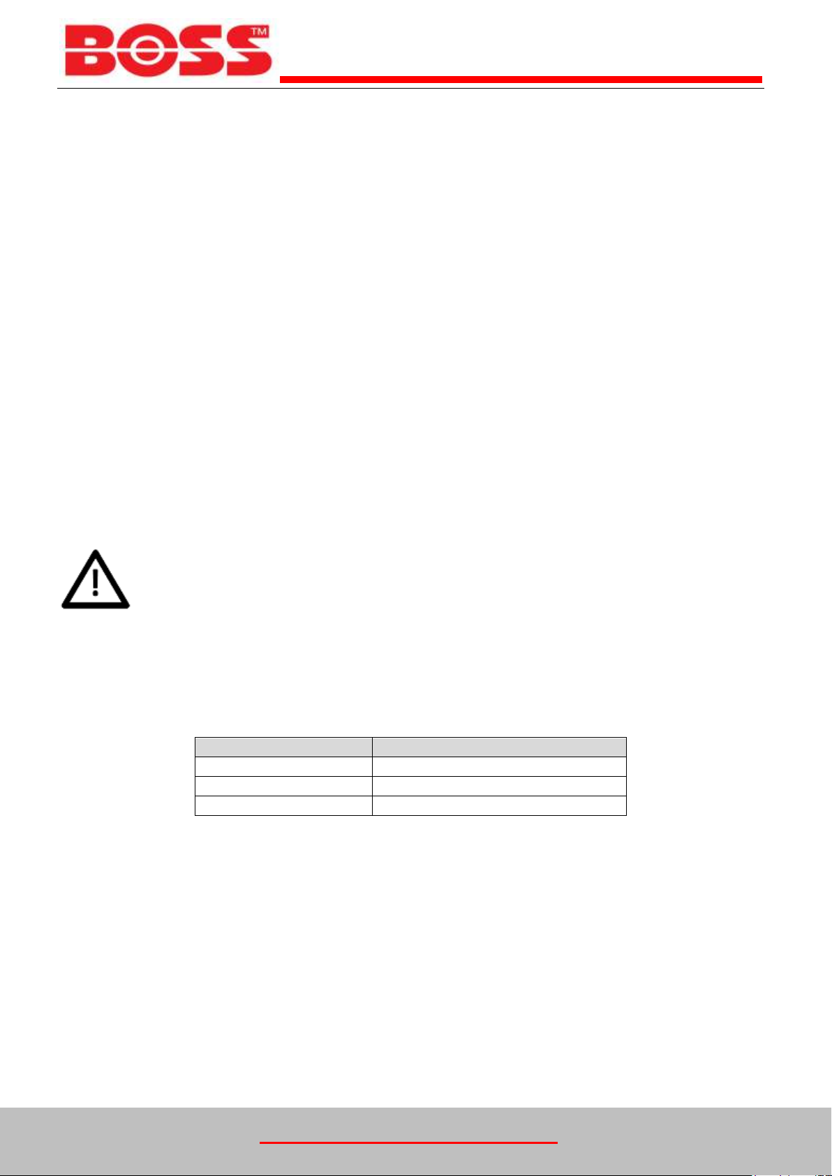
Mains Water Pressure
Requirement
Below 1 Bar
No Restrictor. Install Filter Only
1 – 4 Bar
Low Pressure Restrictor (coloured)
Above 4 Bar
High Pressure Restrictor (white)
Installation of mini mechanical units
Remove the appropriate coverings.
Ensure that the float valve is set to its lowest position.
All pipework connections are to be made with appropriate proprietary jointing compound. PTFE is not
permitted.
Connect the overflow pipework.
Connect the mains water pipework.
Connect the system pipework.
Open the system isolation valve.
Check the break tank internal pump suction filter is present and clear.
Connect the electrical supply to the fused connection block / fused spur as appropriate.
Set the range and Diff on the pressure control switch.
Connect the boiler to the boiler interlock connection block, High / Low Switches
Flow Restrictors
Pressurisation equipment fitted with a plastic, side-entry torbeck valve must be fitted with a filter
and – depending on the mains water pressure – a flow restrictor. Failure to do this may result in
damage to the equipment.
Two different flow restrictors are supplied with the equipment, both of which include an integral filter. The
selection of the appropriate flow restrictor is based on the maximum mains water pressure at the point of
installation. Please refer to the following table for selection.
 Loading...