

Boss MSC13171 Installation Instructions Manual
FormNo.MSC12976RevA
Power/GroundExtensionKit
PartNo.MSC13171
InstallationInstructions
WARNING
CALIFORNIA
Proposition65Warning
WARNING:Thepowercordonthisproduct
containslead,achemicalknowntotheState
ofCaliforniatocausebirthdefectsorother
reproductiveharm.Washhandsafterhandling.
Safety
•Alwaysfollowthevehiclemanufacturer’ s
recommendationsrelatingtosysteminstallation.
•Duetothevarietyofequipmentthatcanbeinstalledusing
theundercarriage,ensurethatthegross-vehicle-weight
rating(GVWR)isnotexceededatanytime.Youmay
needtoweighthevehicleandaddballastorlimitthe
payloadofthevehicletocompensate.
Installation
DANGER
Vehicleenginescontainmovingpartsandcan
becomeextremelyhot,capableofcausingsevere
burnsandseriousbodilyharm.
Shutofftheengineandallowitsufcienttimeto
cooldownbeforeinstallingthiskit.
DANGER
Vehiclebatteriescancausedangerouselectrical
shocksthatcouldleadtosevereburnsordeath.
Disconnectyourbatterybeforeinstallingthiskit.
Note:Applydielectricgreasetoallelectricalconnections.
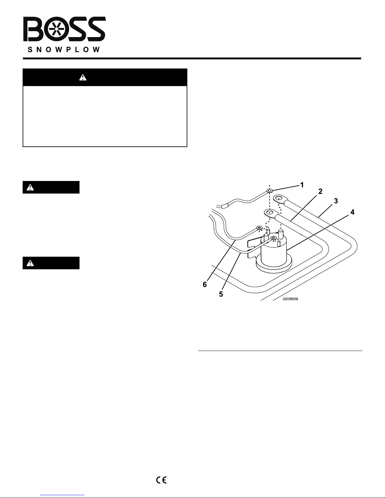
1.Connectthewhite/blackwirefromthewireharnessto
thesmallpostonthepumpsolenoid(Figure1).
Figure1
1.Redfusedwire
4.Pumpsolenoid
2.Longbatteryextension
cable
5.Brownwire
3.Redpower/groundcable6.White/blackwire
2.Connectthebrownwirefromthewireharnesstothe
othersmallpostonthepumpsolenoid(Figure1).
Note:Thewiresmaygooneithersmallpost,but
shouldnotshareapost.
3.Mountthepumpsolenoidinsidetheengine
compartmentofthevehicle,ensuringthatitstaysinan
uprightpositionanddoesnotcontactthebody,hood,
orotherconductivematerialonthevehicle.
4.Connecttheredpower/groundcabletothelargepost
onthepumpsolenoid(Figure1).
5.Connectthelongbatteryextensioncabletotheother
largepostonthepumpsolenoid(Figure1).
©2016—BOSSProducts
P .O.Box787
IronMountain,MI49801
Registeratwww.bossplow.com.
OriginalInstructions(EN)
PrintedintheUSA
AllRightsReserved
*MSC12976*A
Note:Thewiresmaygooneitherlargepost,but
shouldnotshareapost.
6.Connecttheblack/redwireattheendofthewire
harnesstoakeyed12V+ignitionsource.
Note:Connectingthewiretoasourcethatisnot
keyedcancausethebatterytodrain.
7.Connecttheblackpower/groundextensioncableto
thenegative(-)batteryterminal(Figure2).
Figure2
1.Blackpower/ground
extensioncable
4.150Afuse
2.Shortbatteryextension
cable
5.Longbatteryextension
cable
3.Fuseholder
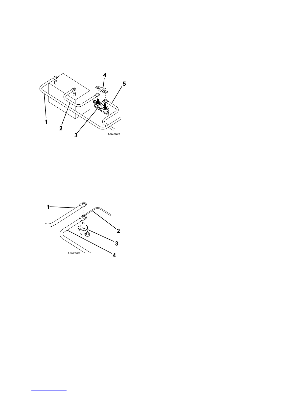
8.Attachtheisolatedgroundstudunderthehoodofthe
vehicle(Figure3).
Figure3
1.Blackpower/ground
extensioncable
3.Isolatedgroundstud
2.Brownwire
4.Blackpower/groundcable
9.Connectthefreeendoftheblackpower/ground
extensioncabletotheisolatedgroundstud(Figure3).
10.Connectthebrownwiretotheisolatedgroundstud
(Figure3).
11.Connectthered,fusedwiretothesamepostonthe
pumpsolenoidasthebatteryextensioncable(Figure1).
12.Attachthefuseholderwithin50cm(20inches)ofthe
vehiclebattery(Figure2).
13.Connectthefreeendofthelongbatteryextension
cabletothefuseholder(Figure2).
14.Connecttheshortbatteryextensioncabletotheother
studonthefuseholder(Figure2).
15.Installthe150Afuse(Figure2).
16.Connecttheremainingendoftheshortbattery
extensioncabletothepositive(+)batteryterminal
(Figure2).
2
 Loading...