

USER MANUAL
QUICK INSTALLATION GUIDE
USER MANUAL
QUICK INSTALLATION GUIDE
0215
BOSS Audio Systems
3451 Lunar Court • Oxnard, CA 93030
www.bossaudio.com | 800.999.1236
Tech Support: www.bossaudio.com/support
PRINTED IN CHINA
VER:1.0 EN
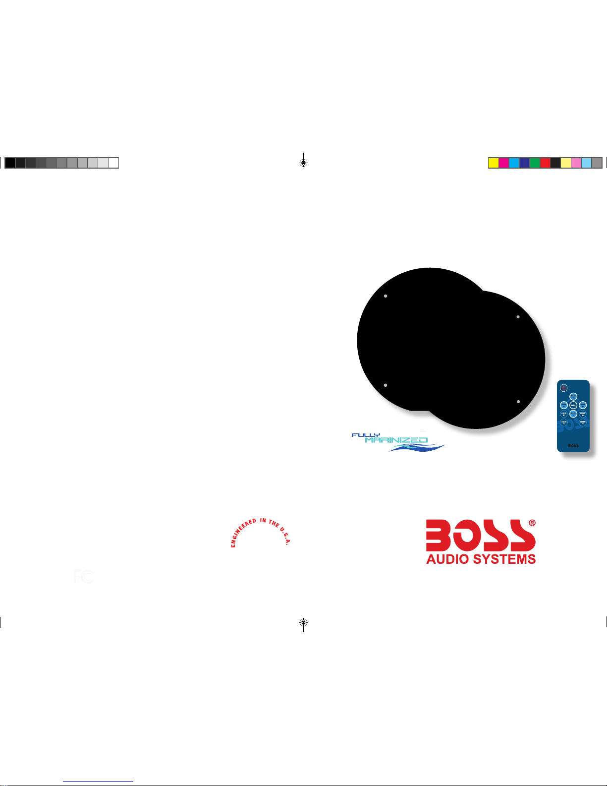
MARINE GRADE
6.5″ COAX SPEAKERS
MRGB65 / MRGB65S
FEATURING 17 COLOR RGB LED’s
and RF REMOTE CONTROLLER
MRGB65 / MRGB65S
MARINE GRADE RGB 6.5” COAX SPEAKERS
MRGB65-UM-DRAFT.indd 2-3 1/16/2015 9:31:36 AM
All rights reserved. No part of this publication may be reproduced, distributed, or transmitted in any form or
by any means, including photocopying, recording, or other electronic or mechanical methods, without the
prior written permission of AVA Enterprises Inc.
Copyright © 2015 AVA Enterprises Inc.
BEFORE YOU START ------------------------------------------------------------------2
IMPORTANT SAFETY PRECAUTIONS
INSTALLATION PRECAUTIONS
WIRE DIAGRAM--------------------------------------------------------------------------3
BEFORE INSTALLING THIS PRODUCT
------------------------------------------4
TECHNICAL SUPPORT
SUGGESTED MOUNTING LOCATIONS ------------------------------------------5
GETTING STARTED
--------------------------------------------------------------------6
SPEAKER TEMPLATE
-----------------------------------------------------------------7
TROUBLE SHOOTING GUIDE
-------------------------------------------------------8
SPECIFICATIONS
------------------------------------------------------------------------8
TECHNICAL SUPPORT
TABLE OF CONTENTS
MRGB65-UM-DRAFT.indd 4-5 1/16/2015 9:31:36 AM

2
ENGLISH
THIS PACKAGE CONTAINS
2x- MRGB65 / MRGB65S Coax Speakers
(Depends on your model)
1x- RF Remote Controller
1x- RGB LED RF Sync Receiver HUB
2x- HUB Wire Extension Kit
2x- Speaker Wire & Mounting Hardware Kit
1x- User Manual / 1x- Warranty Card
USER MANUAL
QUICK START GUIDE
Thank you for purchasing this
MRGB65 6.5” Coax Speakers w/ RGB LED RF Controller
Please read through these instructions carefully so you will know
how to operate your model properly.
After you have nished reading these instructions, keep this
document in a safe place for future reference.
BEFORE YOU START
IMPORTANT SAFETY PRECAUTIONS
BE SURE TO OBSERVE THE FOLLOWING GUIDELINES:
- Do not turn up the volume so high that you can’t hear what’s around you.
- Use caution or temporarily discontinue use in potentially hazardous
situations.
■ Do not operate mobile video equipment while driving a motorized vehicle
■ Safe vehicle operation and safety consideration of others should always
be your highest priority.
■ Set your volume control at a low setting, then slowly increase the sound
until you can hear it comfortably without distortion, or ear discomfort.
■ In the event you should notice smoke, strange noises or odor from this
product, or any other abnormal signs, immediately turn off the power and
consult your dealer or the nearest authorized BOSS AUDIO Service Center.
Using this product in this condition may result in permanent damage to the
system.
INSTALLATION PRECAUTIONS
WARNING - Always consult with a professional installer
■ Do not attempt to install or service this product by yourself. Installation or
servicing of this product by persons without professional training and
experience in electronic equipment and motorized vehicle accessories may
be dangerous and could expose you to the risk of electric shock, injury or
other hazards
■ Refer any repairs to a qualied BOSS AUDIO SYSTEMS Service Center
■ The MRGB65 LED RGB SYNC HUB should be wired directly to a normally
open switch or relay.
■ When wiring directly to the vehicles battery, be sure to disconnect the
batteries negative terminal wire before starting any wiring procedures,if extending the main power wire, it is suggested that an optional fuse and fuse
holder (not included) with minimum rating of 10 Amperes be in-line with the
positive battery terminal
■ The ground cable length should not exceed 18-inches (See wiring diagram pg 4)
■ The MRGB65 has a weather resistant design, it should not be submerged
in or under water under any circumstances
■ Use only the installation parts provided with the MRGB65
FCC COMPLIANCE STATEMENT
This device complies with part 15 of the FCC Rules. Operation is subject to
the following two conditions:
(1) this device may not cause interference, and
(2) this device must accept any interference, including interference that may
cause undesired operation of this device.
MRGB65-UM-DRAFT.indd 2-2 1/16/2015 9:31:38 AM

3
4
ENGLISH
ENGLISH
GROUND CABLE
METAL FRAME
FUSE REPLACEMENT
WITH ATO TYPE ONLY
3 AMP
YOUR AMPLIFIER
SPEAKER 1
SPEAKER 2
+
-
+
-
+12V BATTERY YELLOW
REMOTE OUT
+12V BLUE
+12V RED
CHASSIS
GROUND
POINT
BATTERY
OPTIONAL DIRECT BATTERY WIRING CIRCUIT
BLACK
OPTIONAL
FUSE AND FUSE HOLDER
(NOT INCLUDED)
CHASSIS
GROUND
POINT
Recommended 16 ~ 18ga Primary Extension Wire
(not included)
CNO
Normally Open
ON/OFF ACC switch
Normally open
ACC switch
(not included)
YOUR
BATTERY
KILL SWITCH
RGB LED 2
RGB LED 1
YOUR RADIO
RGB LED 2
RGB LED 1
SYNC OUT
SYNC IN
RGB SYNC HUB
NOTE: ONLY USE SYNC IN/OUT WHEN CONNECTING
TWO OR MORE HUB SYSTEMS TOGETHER
INSERT
INSERT
RGB LED
EXTENSION WIRE
TO CONNECT MORE THAN
ONE SET OF MRGB65 TOGETHER,
PLUG THE SYNC OUT TO THE SYNC
INPUT OF THE NEXT SYSTEM
STRIPPED WIRE NEGATIVE
12FT
Splice BUTT connectors
3A
WIRE DIAGRAM
BEFORE INSTALLING THIS PRODUCT
When replacing the fuse, be sure to only use a fuse
of the rating specied on this product.
To avoid short-circuiting, cover any disconnected leads with insulating
tape. It is especially important to insulate any unused wires, which if left
uncovered may cause a short circuit. When connecting other devices to this
product, refer to the manual for the product to be connected. The black cable
is ground, make sure to connect the ground wire rst.
Ensure that the ground cable is properly connected to metal parts of the
vehicles body frame or direct to the battery if your vehicle does not have a
grounded chassis frame The ground cable of this units power amp and a
second powered system must be connected to the frame separately with
different screws. If the screw for the ground wire loosens or falls out, it
could result in re or malfunction.
To avoid potential shorts in the
electrical system, be sure to
disconnect the (–) battery cable before
installation. Use this unit with a 12-volt
battery and negative grounding only.
Failure to do so may result in a re or
malfunction.
TOOLS NEEDED:
- Wrench and/or Pliers
- #2 Phillips screwdriver
- Crimp tool
- Handsaw / Jig Saw
- Electrical tape
TECHNICAL SUPPORT
1-800-999-1236
www.bossaudio.com/support
CAUTION!! Do not ground or short the RGB wires
- Do not touch the speaker ex wire
- The RGB HUB controller should be installed in a non-metal and dry location
- Secure all wiring with wire ties
- Properly seal connections to ensure water tight connections
MRGB65-UM-DRAFT.indd 3-4 1/16/2015 9:31:38 AM

5
6
ENGLISH
ENGLISH
Always double check for mountig
depth limitations, never cut before
you check
SUGGESTED MOUNTING LOCATIONS
The MRGB65 can mounted in three different congurations:
GETTING TO KNOW YOUR
MRGB65 RF CONTROLLER
GETTING STARTED
1
RF CONTROLLER
2
POWER ON / OFF
3
MODE UP
4
AUTO DEMO
5
SPEED UP
6
BRIGHTNESS UP
7
BRIGHTNESS DOWN
8
MODE DOWN
9
COLOR DOWN
10
COLOR UP
11
SPEED DOWN
1
2
3
4
5
6
7
8
11
10
9
CAUTION!! Using other mounting methods may void this warranty
REPLACEMENT BATTERY - CR2032
1) RF controller range: Up to 25ft (LoS)
2) Do not obstruct the RF remote with metal
3) Always keep away from small children
4) Do not store in direct sunlight
MRGB65-UM-DRAFT.indd 5-6 1/16/2015 9:31:39 AM

7
8
ENGLISH
ENGLISH
SPEAKER TEMPLATE
To avoid battery exhaustion be sure to run the vehicles engine
while using this product. Using this product without running the
engine can drain the battery.
Tips:
EN
TROUBLE SHOOTING GUIDE
CAUTION!!
ADJUSTMENT OR ALTERATIONS OF THIS DEVICE MAY RESULT
IN HAZARDOUS RADIATION EXPOSURE.
TROUBLE CAUSE SOLUTION
RGB Unit will not turn on
The fuse is blown Check / replace the fuse
Switch not engaged Turn to on position
No sound is heard
Blown speaker Replace faulty speaker
Volume is low / muted Press the volume level up
Device is paused or muted
Check your devices playing /
volume status
Unit has become
unresponsive Power glitch or interference
Disconnect power for
10 seconds to reset
SPEAKER GENERAL SPEC
• Speaker Type: Full Range
• Conguration: Coaxial
• Wo of er S iz e: 6. 5”
• Tweeter Size: 1”
• Mounting Depth: 2-5/8”
• Mounting Diameter: 5-3/4”
• Peak Power Handeling: 200 Watts
• Impendance: 4Ω
• Sensitivity (1W/1M): 88dB
• Frequency Response: 70 Hz to 20 kHz, ±1 dB
SPECIFICATIONS
RGB HUB GENERAL SPEC
• Power source: 14.4VDC (10.8V ~ 16V allowable)
• Grounding System: Negative type
• M a xi m u m C u r r en t C on s u mp t i on : 1 .5 A
• Unit Weight: 2.08lbs / 0.94kg
• Storage Temperature: 5oF to 113oF / -15oC to 45oC
• Operation Temperature: 14oF to 104oF / -10oC to 40oC
TECHNICAL SUPPORT
1-800-999-1236
www.bossaudio.com/support
OD
TEMPLATE FOR REEFERENCE ONLY - NOT TO SCALE
BE SURE TO MOUNT SPEAKER IN THE CORRECT ORIENTATION
TO ALLOW FOR WATER DRAINAGE
WATER DRAINAGE HOLE - DO NOT BLOCK
MRGB65-UM-DRAFT.indd 7-8 1/16/2015 9:31:39 AM
 Loading...