

Page 1
Page 2
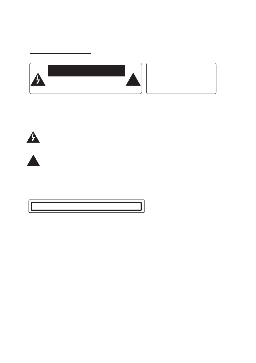
PRECAUTION
CAUTION
RISK OF ELECTRIC S HOC K
DO NOT OPE N
CAUTI ON: TO REDUCE THE RI SK OF E LECTRIC SH OCK , DO NOT REMOVE
COVER ( OR BA CK). NO USER S ERV ICE ABLE PART S INS IDE. REFER
SERVICIN G TO QUALIFIE D SER VIC E PERSONNE L.
The lighte nin g fla sh wi th ar row hea d symbol, within an equilateral tria ngl e, is
intended t o ale rt th e use r to th e pre sen ce of u ninsulated dangerous voltag e
within the p rod uct s enc los ure t hat m ay be o f suffic ien t mag nitude to constitute
a risk of elec tri c sho ck to p ers ons .
The exclam ati on po int w ith in an e qui lateral triangle is intended to aler t use r to
the presen ce of i mpo rta nt op era tin g and maintenance (servicing) inst ruc tio ns
!
in the liter atu re ac com pan yin g the a ppliance.
WAR NIN G: TO RE DUC E THE
RISK OF FIRE OR E LEC TRI C
SHOCK, DO NOT E XPO SE
!
THIS APPLIAN CE TO RAIN OR
MOISTURE.
CLASS 1 LASER PROD UCT
Laser prod uct s ymb ol: l oca ted o n the r ear panel of the unit, indicate this pla yer i s a cla ss
laser prod uct , onl y use w eak l ase r and n o hazardous radiation outside of the u nit .
1.Read thr oug h thi s ins tru cti on ma nual before installation and use.
2.Before r emo vin g the u nit , rem ove t he di sc from the unit first.
3.Do not ope n the c ove r or to uch a ny of t he co mpo nents exposed out of the unit, only f or
qualifie d tec hni cia ns.
4.Do not exp ose t he un it to d ire ct su nli ght or nearby objects that radiate hea t to av oid
damage the u nit .
5.Do not pla ce th e uni t in mo ist a nd hu mid c onditions.
6.Please e nsu re th e ven til ati on ho les are not covered to avoid overheati ng an d mal fun cti on.
7.Clear th e pan el an d cas e wit h sof t dry c lot h only, do no t app ly an y kin d of thinner,
alcohol or s pra ys.
Page 3
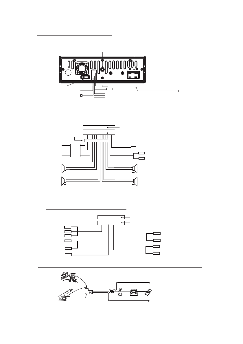
Wires Con necti on Description
Description of Wires Connection
Fixing Screw Bolt
GREEN
BLACK
Wiring Connecting Socket 2
1. Parking wire must be connected. And the parking brake must be engaged in order for the monitor to work.
2. Use the clip end of the Ground Wire provided by manufacturer to connect Mounting Screw, using the other
end of the Ground Wire to connect the negative pole of the power source. Otherwise, the video on screen
maybe flashes.
PARKING LINE
WHITE
REVERSAL LINE
BLACK
IPod IN
USB LINE IN
Wiring Connecting Socket 1
Radio Antenna jack
BLACK
KEY GROUND(BLACK)
KEY A(BROWN)
KEY B(YELLOW)
BLACK
from the bottom cover of the chassis
video out yellow
Description of the Wiring Diagram for Socket 1
WIRING CONNECTING SOCKET 1
WIRING CONNECTING PLUG 1
WOOFER LINE OUT
BLACK
FRONT AUDIO RCA OUT
GRAY
GRAY / BLACK
VIOLETGREEN
VIOLET / BLACK
GREEN
RED R
WHITE L
+
FRONT
RIGHT
SP
+
REAR
MEMORY B+
BLACK(GND)
IGNITION SWITCH
FRONT
LEFT
SP
REAR
ISO CONNECTOR
YELLOW
FUSED
FILTER
BOX 1A
& 10 A
RED
FUSES
BLUE AUTO ANT
+
WHITE
WHITE / BLACK
+
GREEN / BLACK
NOT ES:
1. On ly spea kers wi th 4 ohms i mpeda nce may b e used.
2. En sure th at the bl ue auto a ntenn a cable d oes not m ake con tact
wit h any gro und con necti on.
Description of the Wiring Diagram for Socket 2
WIRING CONNECTING SOCKET 2
RED R
WHITE L
YELLOW VIDEO
YELLOW
YELLOW
YELLOW
BROWN
AV IN
GREY
VIDEO RCA OUT
BLACK
REAR VIEW CAMERA
BACKGROUND AUDIO RCA OUT
WIRING CONNECTING PLUG 2
GREY
REAR AUDIO RCA OUT
BLUE
RED R
WHITE L
RED R
WHITE L
Descri ptio n of Con nec ting t he Par kin g Brak e Line t o the P arki ng Bra ke Sy stem B uilt i n a Car
Par king br ake
Par king br ake wir e(Gre en)
Par king br ake swi tch
(in side th e car)
NOTE: after connecting the Parking Line, the video on the small monitor of the front panel will be display only after braking the car.
To met allic b ody or ch assis o f the car
Page 4
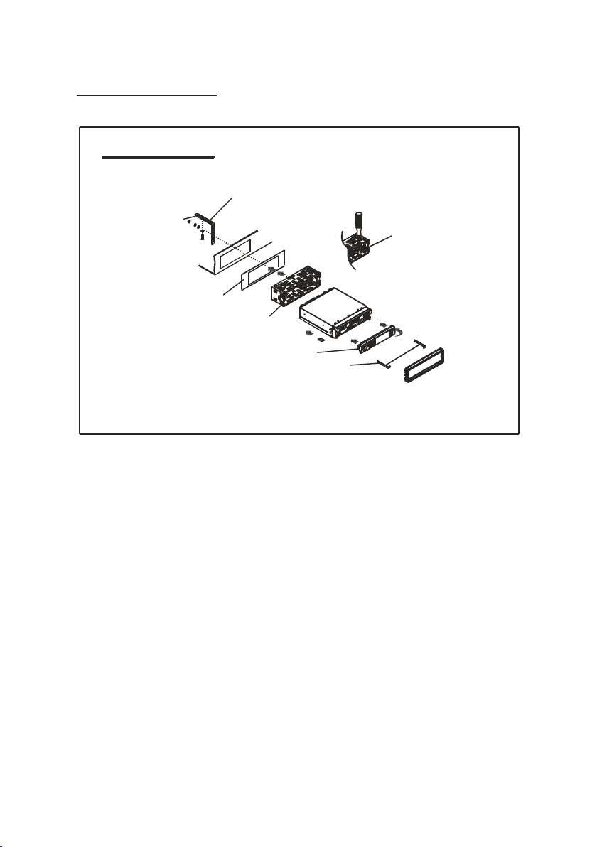
UNIT INSTAL LATION
INS TALLATIO N INSTRU CTION S
THE UN IT IS INSTA LLED TO BE AN AN TI-THE FT ONE. THE CH ASSIS
OF THE U NIT WEARS A SL IDING MET AL HOUSIN G. PLEAS E DO THE
CONN ECTION O F THE PO WER, SPEA KERS AND ANTE NNA ACCO RDING
TO THE R EQUIREM ENT OF THE INS TRUCTI ON BOOK , THEN I NSTALL
THE SL IDING ME TAL HOUSIN G IN THE CAR AS FO LLOWS.
METAL ST RAP
TO BOO ST UP THE CAPABILI TY OF
ANTI -JAMMI NG, PLEA SE FIX THE
METAL ST RAP ON THE METAL
CONN ECTED TO THE B OTTOM
BRAC KET OF THE CAR .
SELE CT THE PROP ER TAB
FOR FI XING THE SL IDING
METAL HOU SING.
DASH B OARD
SLI DING METAL HOU SING
FRON T PANEL
TO DRAW TH E CHASSIS O UT OF
THE SL IDING ME TAL HOUS ING,
INSE RT THE LEFT AND RI GHT KEY
PLATE S INT O THE RI GHT POSIT ION
OF THE 2 SI DES OF CHASS IS.
UNIT C HASSIS
PLAS TIC TRIM OU T
Page 5
GENERAL KNOWLEDGE A BOUT RE MOTE CO NTROL
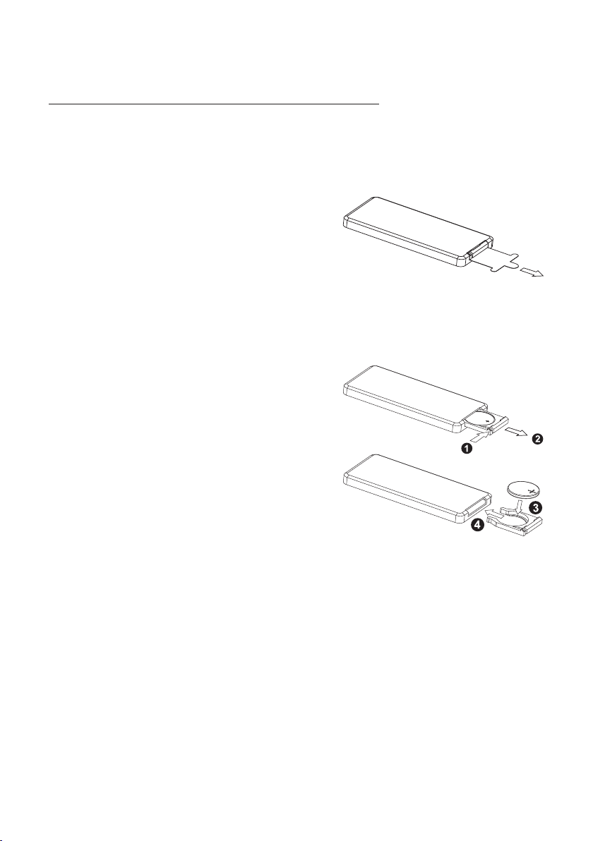
1. Removing in sulat ing she et
If using remot e contr ol for th e first t ime, you
can see an insulating s heet at t he bott om
side of remote c ontro l as righ t.
you must remov e the ins ulati ng shee t as right.
Otherwise, t he remo te cont rol is di sabled.
2. Replace lit hium ce ll
If the electri c energ y of lith ium cel l is weak,
replace it.
1) Press and hold the mov able bl ock as di rection
indicated by arrow 1 as r ight, a t one tim e pull
cell holder out of remo te cont rol as di rection
indicated by arrow 2 as r ight.
2) Replace the old cell b y a new one w ith (+)
polarity sid e upwar d as righ t.
3) Insert the ce ll hold er into r emote c ontrol again
as right.
3. Note about us ing rem ote con trol
1) You should face the emit ting wi ndow of r emote c ontrol towards the senso r
window of the unit.
2) Operation angle fo r front p anel: Ab out 30 de gree
3) The di stance between the emitting win dow of re mote co ntrol and the sensor
window of the unit : < 5M .
4. Wa rning f or lith ium cells of remote contro l
1)Cell leakage may ca use dam age to re mote co ntrol.
2)Do not throw cells in to fire , it may ca use explosion.
.
3.To avoid risk of acciden t, keep c ells ou t of reac h of children.
Page 6
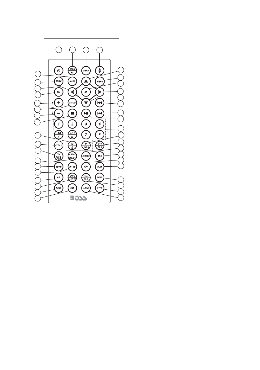
Remote Co ntrol D escription
3
27
35
14
29
32
9
34
13
31
30
41
24
28
21
22
26
25
23
36
37
1
1. ANG BUTTON
2. MENU BUTTON
4
2
33
6
8
5
7
10
11
40
12
16
15
18
17
19
20
39
38
3. POWER BUT TON
4. ^ BUTTON
5. >>| BUTTON
6. > BUTTON
7. |<< BUTTON
8. v BUTTON
9. SEL BUT TON
10. PLAY/PAUS E BUT TON
11. NUMBER(0~10,+10
-10) BUTTONS
12. 10+/PT Y BUTTON
13. SETUP BUTTON
14. MODE BUT TON
15. APS BUTTON
16. SEARCH B UTTON
17. RDM BUTTON
18. RPT BUTTO N
19. SUBTIT LE or B UTTON
20. TITLE/PBC BUTTO N
21. VIEW-ANGLE or ST/MONO BUTTON
22. ZOOM BUT TON
23. LANG/L /R/ ST BUTTON
24. CLOCK BU TTON
25. A-B BUTTON
26. INTRO BU TTON
27. EQ/OPE N BUT TON
28. LOC/DX o r SLO W-FWD BUTTON
29. MUTE BUT TON
30. STOP BUTT ON
31. VOLUME - BUT TON
32. < BUTTON
33. OK BUTTON
34. VOLUME + BUT TON
35. BAND BUT TON
36. PROG BUT TON
37. OSD BUTTON
38. LOUD BUT TON
39. STEP BUTTON
40. TA BUT TON
41. AF BUTTON
Page 7
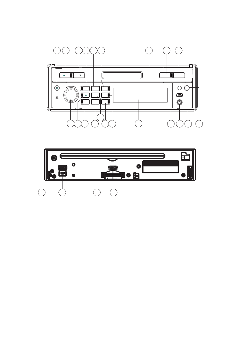
Locatio ns and Na mes of Controls on or in the un it
20
10
SEL
- VOL +
11
BAND APSMODE
INT
3
2
1
RDM
4
RPT
-10
+10
5
6
2
MUTE
19
18
8
13
12
9
15
16
17
14
22
Front Panel
SD/ MMC
721
5
The Front Facet af ter rem oving front panel
3
2
TA / AF OPEN
23
1
REL
IR
AUX
4
24
6
1. OPEN button
2. POWER/MUTE bu tton
3. Monitor
4. AUX socke t
5. Disc Slo t
6. USB Jack
7. SD/MMC Card Slo t
8. MODE button
9. SEL button and VOL knob
10. ^ button
11. v butt on
12. PLAY/PAUSE/1 button
13. INT/2 button
14. RPT/3 button
15. RDM/4 b utton
16. - 10 / 5 button
17. + 10 / 6 button
18. BAND bu tton
19. APS butto n
20. EJECT butt on
21. RESET butt on
22. Small L CD Scre en
23. IR Remo te Sens or
24. REL button
25. TA/AF button
Page 8
Common Operat ion
1. To turn on/off t he un it
In power off mode, short press any butto ns ex cep t REL to turn on the unit.
In power on mode, l ong p res s the P OWE R but ton o n the f ront panel or short press the
POWER button on t he re mot e con tro l to tu rn of f the u nit .
2. To slide the monitor of the Car Audio System out of the cha ssi s
Shortly press t he OP EN bu tto n on th e fro nt pa nel o r long press the OPEN button on
the remote cont rol c an sl ide t he mo nit or of t he Ca r Audio System out of the chassis or
slide it into the c has sis .
3. To adjust the angle of the monitor
press the ^ or v butt on on t he mo nit or to a dju st th e ang le
of the monitor.
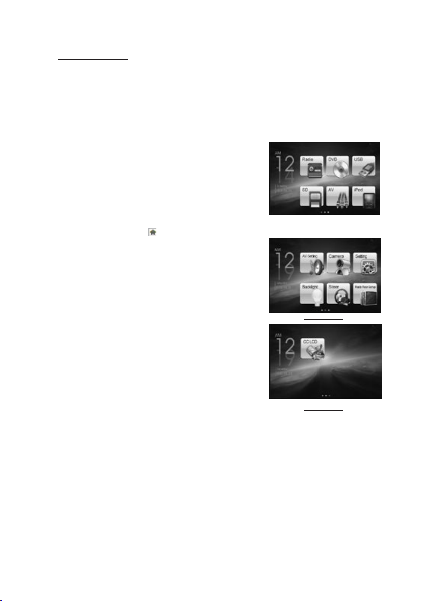
4. To select function mode
Press the MODE bu tto n to se lec t RAD IO, D ISC ( Aft er
inserting a dis c), U SB( Aft er in ser tin g a USB s tor age),
SD/MMC CARD(A fte r ins ert ing a S D/M MC ca rd) , AUX ,
or iPod mode.
In any mode, tapp ing t he ic on (a fte r pop pin g up Ke y-
Mod e Menu 1
board interfa ce fo r dis c/U SB/ car d) ca n pop u p Mode
Menu 1 as righ t ima ge, t hen t ouc h and h old a ny pl ace
and slide le ftw ard t o dis pla y the M ode M enu 2 a nd Mo de
Menu 3 . finally ta p one i con i n the M ode M enu s to en ter
your desired mo de.
5. To adjust sound level
Rotate the VOL kno b on th e fro nt panel or press and
hold the + or - butto n on th e rem ote c ont rol w ill a dju st
the volume leve l.
Mod e Menu 2
6. To adjust audio and turn on or off the touch screen
Press the SEL butt on co nti nuously to switch between
VOLUME, BASS, TREBLE, BALANCE and FADER.
after switchi ng on a d esi red a udi o mod e abo ve, r otate
the VOL kn ob on t he fr ont p ane l or press or hold the
VOL+ or VOL- butt on on t he re mot e con tro l to se t it.
Long press the SE L butt on to t urn on/off th e tou ch sc reen.
7. To mute sound
Press the MUTE bu tto n on th e rem ote c ont rol t o tur n
Mod e Menu 3
on/off MUTE mode.
Pressing the PO WER b utt on on t he fr ont p ane l sho rtl y also can turn on/off MU TE mode.
8. To display clock time
Press the CLK but ton t o dis pla y clo ck ti me on t he mo nitor screen.
After sliding th e mon ito r int o the c has sis , pre ssing the CLK button can display clock
time on the small L CD.
9. To select a des ire d EQ mo de
Press the EQ butt on on t he re mot e con tro l to se lec t one o f the preset music equalizer
curves: POP, ROCK, CLAS, FLAT. The s oun d effect will be cha nge d.
10. To tur n on/off L OUD m ode
Press the LOUD bu tto n on th e rem ote t o tur n on/ off L OUD m ode .
When turning on L OUD m ode , it wi ll en han ce ba ss le vel immediately when bass is not
enough.
Page 9
11.To remove the front pa nel
press t he REL button to fl ip down t he front panel from
the mai n unit, t hen hold the right en d of the front panel
to push l eftwa rd and pull away.
12.To reset the pl ayer
When th e monit or , the small LCD disp lay or some
butto ns are no t working or sound is d istorted, remov e
the fro nt pane l, then press the RES ET bu tton to r eset
the pro gram to f actory default.
13.To cal ibrate the scre en
To pop up Calibr ati on interfa ce du ring media p lay back,
first p res s the STOP button, then pre ss the ZOOM butto n,
final ly pr ess the ^ and v bu tto ns in turn.
In the in ter face, you ca n hav e calibrat ion b y accurate ly
tappi ng th e cross curs or.
Audio Se ttin g
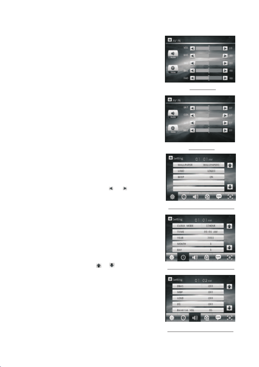
14.AV Setti ng
In the Mo de Me nu 2 screen, t app ing the AV Setting ic on
can pop u p the AV Se tti ng interfa ce as r ight.
In the AV Settin g int erface, ta ppi ng the Audio or Video
icon ca n swi tch betwee n Au dio S etting and Vide o Set ting
inter fac e.
In thes e 2 int erfaces, t app ing the or ico n can s et
one ite m of th em.
In the Aud io Se tting inte rfa ce, you can se t the v alue of
the VOL UME , BASS, TREBLE, B ALA NCE and FADER .
In the Video S ett ing interf ace , you can set th e val ue of
the BRI GHT NESS, CONT RAS T, SATUR ATIO N and HUE.
15.Ge neral Setting
In the Mo de Me nu 2 screen, t app ing the Sett ing i con can
pop up th e 1st p age of the Gen era l Setting. Then t app ing
one ico n in th e bottom row c an po p up the other p age s.
In thes e pag es, tappin g the o r icon can sel ect a
setti ng it em. After sele cti ng a setting i tem , tap its valu e
to set it .
In the 1s t pag e, you can set t he WALLPAPER, LOG O
and BEE P.
In the 2n d pag e, you can set t he CL OCK MODE, TIME,
YEAR, MONT H and D AY.
In the 3r d pag e, you can set t he DB AS, MBP, LOUD, EQ
and REV ERS E VOI.
Vid eo Set tin g
the 1 st Pa ge of th e Gene ral S etti ng
the 2 nd Pa ge of th e Gene ral S etti ng
the 3 rd Pa ge of th e Gene ral S etti ng
Page 10
the 4 th Pa ge of th e Gene ral S etti ng
the 5 th Pa ge of th e Gene ral S etti ng
the 6 th Pa ge of th e Gene ral S etti ng
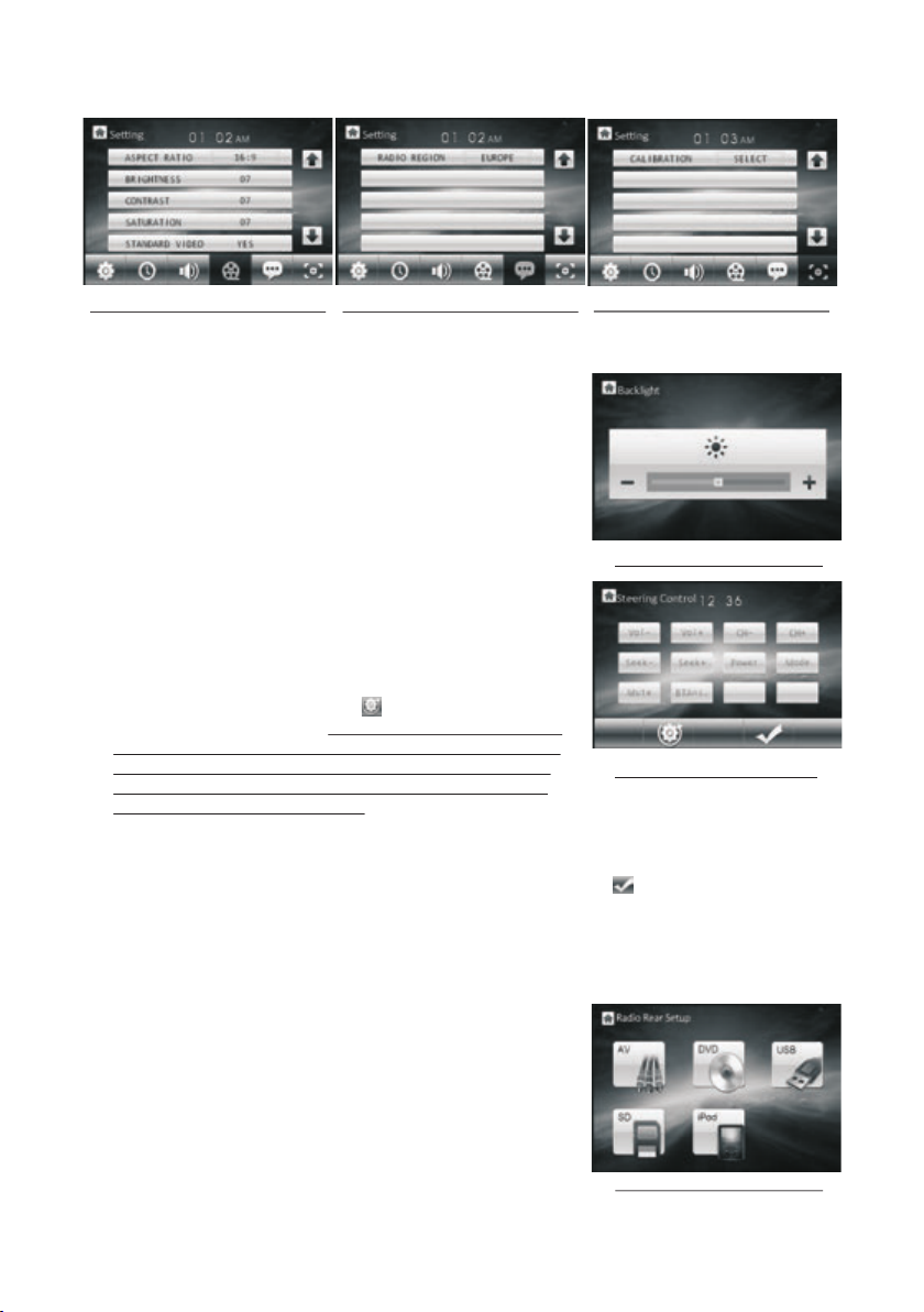
In the 4t h page, you can set t he ASPECT RATI O, BRIGHNE SS, CONTRAST, SATU RATION and STANDA RD VI DEO.
In the 5t h page, you can set R ADIO REGION.
In the 6t h page, you can cal ibrate the s cre en.
16. Bac klight Settin g
In the Mo de Menu 2 screen, t apping the B ack light icon
can pop u p the Backlight S etting int erf ace.
In the in terface, tapp ing the - or + ico n can s et the
the B ack ligh t Sett ing i nter face
backl ight.
17. Fun ction setting a nd applica tio n for Steer bu tto ns
In the Mo de Menu 2 screen, t apping the S tee r icon can
pop up th e Steering Cont rol interf ace .
In the in terface, tapp ing the icon can re store the
user se ttings to zero an d display Pl eas e press stee r
the 1th k ey function , the n long press the 1s t button
in the st eer to display Pl ease choos e ste er the 1th
key fun ction , tap one fun ction icon in the S teering
the S tee ring C ontr ol in terf ace
Contr ol interface su ch as vol-.
Set the f unctions of the o ther steer butt ons as the und erl ined step ab ove.
After fi nishing funct ion settin g of al l steer butt ons , t ap the icon to s ave .
CH- and C H+ : In radio mode, t o select pre vio us or next mem ory s tation.
Seek- a nd Seek+ : In disc/ USB/card mode , to play prev iou s or next trac k/
chapt er; In radio mode , short press to ma nually tun e dow n or up for a desi red
stati on, long press to a utomaticall y search dow n or up f or an availa ble station.
BTAns. : To receive a co min g telephon e.
18. Rad io Rear Setup
In the Mo de Menu 3 screen, t apping the R adi o Rear
Setup i con can pop up the Ra dio Rear Set up in terface.
In the in terface, tapp ing the AV, DVD, USB , SD or i Pod
icon ca n enter the backg round audi o out put mode of
the AV, DVD, USB , SD or i Pod and pop up t he fore groun d radio interfa ce as next pag e.
the R adi o Rear S etup i nte rfac e
Page 11

The icons in t he fo reground r adi o interfac e des cribe
as foll ows :
: To return to the R adi o Rear Setup i nte rface.
< and > : To automatical ly search up or dow n for
an avai lab le station .
CH- and C H+ : To man ual ly search up o r dow n for
a desir ed st ation.
19. Cha nge Color of the LC D
In the Mo de Me nu 3 screen, t app ing the CC LCD i con
can pop u p the C C LCD interf ace .
In the in ter face, tapp ing t he or icon can c han ge
the col or of t he LCD. When t he RE D word chang e to
CUSTO, tap pin g the - or + icon ca n set t he value of th e
R, G and B.
C H - C H +
the F ore grou nd Rad io in terf ace
Radio O per ation
1. To enter RADI O mode(MOD E but ton or RADIO i con)
When yo u use MODE but ton o r Mode Menu 1 (t apping
RADIO i con) to ente r RAD IO mode, it wi ll display R adio
inter face 1 as righ t.
In the Ra dio interf ace 1 , tapping th e MENU icon ca n pop
up the Ra dio interf ace 2 a s right.
In the Ra dio interf ace , tapping th e icon can pop u p
the Volu me interfa ce 3 as r ight. In the Vo lume inter face,
tappi ng the - or + icon c an ad just the vol ume level.
* The fun ctions of th e ico ns in the radi o interfac e are same
as the sa me buttons i n the r emote cont rol or in the ma in
unit.
2. BAND B UTT ON
In RADI O mod e, press the B AND b utton on the r emo te
contr oll er or on the fro nt pa nel to selec t you r desired ra dio
band of F M1, F M2, FM3, AM1 and AM 2, an d the select ed
band wi ll be d isplayed o n the small monit or on the front pan el.
3. TUNE/SE EK UP /DOWN BUTTONS
In RADI O mod e:
1) Long p ress the >>| or |<< b utt on to automa tic ally searc h up
or down f or a av ailable st ati on from the cu rre nt frequen cy.
2) Brie fly p ress the >>| o r |<< b utton to man ual ly search up o r
down wi th st ep by step for y our d esired sta tio n from the
curre nt fr equency.
the C C LCD i nter face
RAD IO inte rface 1
RAD IO inte rface 2
RAD IO inte rface 3
Page 12

4. APS BUT TON
In RADI O mod e:
1) When l ong pressing th e APS button, the ra dio s earches fr om th e lowest fre que ncy and
check s the s ignal stre ngt h level unti l 1 cyc le search is f ini shed. And the n the 6 s trongest
stati ons a re preset to t he co rrespond ing p reset numb er me mory bank. The AS op era tion
is impl eme nted in each b ank o f the select ed ba nd. (It can st ore 3 x6 station s for F M and
2x6 sta tio ns for AM)
When th e AS o per ation is fin ish ed, it will sc an ea ch preset st ati on for 5 secon ds in F M or
AM band fr om M1 w hen APS button i s pre ssed brief ly. After th e scanning is fin ished,
broad cas ting will re sum e on the M1.
2) When p res sing the APS but ton b riefly, the radio wil l scan each pr ese t station for 5
secon ds in F M or AM band from M 1. Aft er finishi ng a ci rcle of scan nin g, it will res ume
broad cas ting on the M1 .
NOTE: I n FM ba nd, FM1,FM 2,F M3 is checke d one a t a time; In AM band , AM1 , AM2 is
check ed on e at a time.
5. PRES ET STATI ON [ 1-6 ] BUTTONS
In RADI O mod e:
1) To memorize t he cu rrent freq uen cy on the curr ent b and, long pr ess a ny of the numb er
butto ns (1 -6) on remot e con trol or on the f ron t panel .
2) To recall the p res et memory on t he cu rrent band , bri efly press o ne of t he preset bu tto ns
[1-6] o n rem ote contro l or on t he front pan el.
6. STER EO/ MONO BUTTON
Press t he ST b utt on on the remo te co ntrol to sel ect t he STEREO or M ONO s ound mode
for FM ba nd.
7. LOC BU TTO N
1) In RAD IO mo de, when the s ign al of the dist anc e radio stat ion i s very weak an d the
recei vin g eff ect is bad dur ing t uning. If th ere i s the word LOC o n the m onitor, pre ss th is
butto n to tu rn off the LOC func tio n, then tune a gai n for the dist anc e radio stat ion ;
2) In RAD IO mo de, when the s ign al of the loca l rad io station s are t oo strong an d the i nter feren ce do esn t allow th e tun er to lock on st ati ons, press t his b utton to tur n on th e LOC
funct ion t o display th e wor d LOC on the mon ito r, then tune ag ain f or the local r adi o
stati ons .
8. PTY (PROG RAM TYPE ) BUTTON
Press t he PT Y but ton shortl y to se lect one of th e fol lowing mod e:
PTY MUSIC gr oup - - PTY SPEECH group -- OF F
When PT Y gro up is o n, press the V OL+ o r VOL- butto n on th e remote con tro l or rotate
the VOL knob on the fron t panel to select o ne of PTY pr ograms as fo llo ws:
<-->N EWS <-->AFFAI RS< -->INFO< --> SPORT<-->ED UCATE<- ->DRAMA<--> CULTU RE
<-->S CIE NCE<--> VARIED <-- >WEATHER<--> FINA NCE<-->CHIL DREN<-->SOC IAL
<-->R ELI GION<--> PHO NE IN<-->T RAVE L<- ->LEISUR E<- ->DOCUMENT< - ->PTY
NONE< --> POP M< -->ROCK M< --> EASY M<-->LIGHT M<--> C LAS SICS<--> OTH ER M
<-->J AZZ <-->COUN TRY <-- >NATION M<-->OLDI ES<-->FOLK M< -->
Page 13

When PT Y gro up is o n, pressin g the 6 n umber butt ons a lso can sele ct on e of PTY
progr ams a s above.
After s ele cting one of t he PT Y pro grams, it wi ll di splay SEEK P TY and aut omatically
searc h for t he station o f the P TY pr ogram. If th e sta tion of the PTY progra m does not
exist , it wi ll display P TY NO NE an d then retur n bac k to the norma l sta tion.
9. AF [ALTERNATIVE FREQ UENCIES] BUTTON
When sh ort p ress the AF butt on on r emote cont rol o r long press t he TA/AF butto n on th e
main un it, t he AF switchi ng mo de is select ed an d the status o f the AF s witching m ode i s
displ aye d by AF segment o n the d isplay.
Segme nt of f: AF sw itching mo de off.
Segme nt on : AF switchin g mod e on, and has RD S inf ormation .
Segme nt fl ashing: AF sw itc hing mode on , but R DS informa tio n is not recei ved y et.
When the AF switchi ng mode i s selected, the radio che cks the s ignal strength
of the AF all the time. The interval of checki ng time o f each AFs depends on
the signal stren gth of th e current station, from a f ew minu te for the strong
station to a few sec onds fo r the weak station. Every t ime whe n a new AF is
stronger than th e curre nt station, it switches o ver to th at frequency for very
short time, and th e NEW FRE QUENCY is disp layed f or 1-2 second. Because
the mute time of the AF s witch ing or the checking time is v ery sho rt, it is almost
inaudible in cas e of norm al program. (When AF flash es on the m onitor, it will
search for the str onger R DS station. If AF and TP flash on the mo nitor, i t can
only search for th e traffic announcem ent sta tion).
In FM mode, when AF is on, S EEK, (SCAN), AUTO-MEM ORY functi ons can
only receive and s ave the R DS program.
10. TA [TRAFFIC ANNOU NCEME NT] BUTTON
Press the TA button on the remote co ntrol o r press the TA/ AF button on the
main unit to turn on TA search mode.
When traffic a nnouncement is transm itted :
1).If the unit is in D isc Pla y mode, it will switch to rad io mode t emporarily.
2).Temporarily s witch es over to an station with tr affic announcemen t, and TA,
TP wi ll be displayed on the moni tor.
* TA interruption functi on:
The cur rent tr affic announ cemen t is cancelled by pressin g TA butto n brief ly.
* When TA is on, SEEK, (SCAN), AU TO MEMORY functions can be receiv ed
or saved only when t raffic program iden tific ation code has been recei ved.
Page 14

Disc, U SB and Card Operati on
1. Load /unlo ad disc , USB or C ard
To play files in a d isc, pr ess the REL button to fl ip
down th e front panel, then i nsert the di sc into the
disc sl ot and flip up the fron t panel and pu sh it onto
the cha ssis till click, th en it will aut omatically play .
To remove the di sc from t he unit, pre ss the REL
butto n to flip down the fron t panel, the n press the
EJECT butt on to eje ct disc from t he disc slot a nd
then yo u can remove it.
To play fil es in a USB storage, fi rstly inse rt the small
end of a US B cable into the mini U SB port, the n insert
the USB s torage into the big e nd of the USB ca ble,
final ly it will automati cally play. The front a nd rear
USB can n ot be played at the sam e time.
To remove the US B stora ge, direct ly remove it .
To play files in a S D/MMC c ard, first ly remove th e front
panel , then insert the SD/ MMC card int o the SD/MMC
card sl ot, finally it will a utomatic ally play.
To remove the SD /MMC ca rd from the SD /MMC card
slot, r emove the front pan el, push in th e card and then
pull it o ut of the Card Slot.
* It supp orts version 1.1/ 2.0 USB and 8 GB S D CARD.
Remar k1: If the disc, USB or S D/MMC card i ncludes
MP3 or WM A files, after loadi ng, it will di splay the
File Pl aying interface a s right.
The File P lay ing interfac e
The F ile s List o f the Pl ayi ng Fol der
If you wa nt to check the diret ory, tap the icon to
displ ay the Files List of th e Playing Fo lder, the
Folde rs List of the Playin g File Forma t or the Root
The F older s List of t he Play ing Fil e Forma t
inter face.
If the di sc, USB or SD/MMC car d includes M PEG4 or
Pictu re files, after loa ding, the sc reen will play vide o.
tap any p lace in the screen to d isplay Key board and
then ta p the icon to pop up the Fi les List of th e
Playi ng Folder, tap the ico n to pop up the Fo lders
List of t he Playing File For mat or the Roo t interfac e.
In the Fi les List or Folders L ist interf ace, tappi ng the
or icon c an file or fol der up or d own.
The Roo t inter face
Tapping the ic on of the f ile, folde r or file form at can en ter it.
In the ro ot interface, the M usic icon is f or audio fil es; the Vide o icon is for im age
files ; the Picture icon is f or Vi deo files. I f there are not any fil es for Music , Vid eo
or Pict ure, you can not ente r it.
Page 15
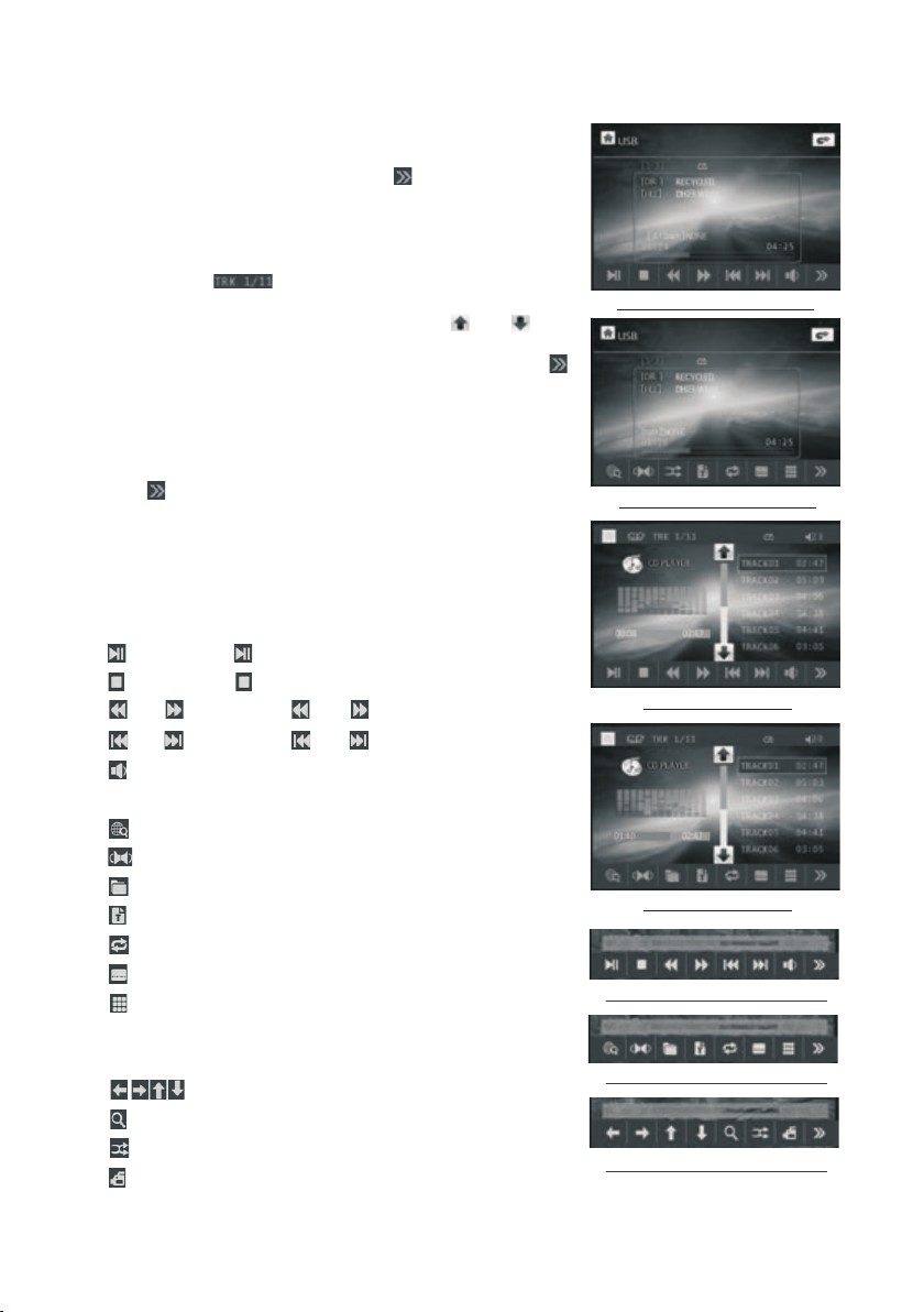
In the Fi le Play ing interface, ta pping any place in th e
recta ngle of t he screen can pop up th e Keyboard-1
of MP3/ WMA, th en tapping the icon c an pop up
the Key board -2 of MP3/WMA.
Remar k2: Aft er loading a CD disc, t he screen will
displ ay the CD i nterface as right . In the CD interface ,
tappi ng the ic on can pop up the numbe r inter face an d use the i cons of the number, <- - and OK to
selec t a desir ed track to play; use t he or icon
to trac k up or dow n. In the bottom row of t he CD
inter face, i t is the Keyboard-1 o f CD, tapping the
icon ca n pop up th e Keyboard-2 of CD.
Remar k3: Dur ing video or image pl aybac k, tap ping an y place o n the screen can pop up t he key board -1 of Video/ Pictu re as right. t hen tap ping
the ico n can pop u p the Keyboard-2 or K ey board -3 of Video/ Pictu re as right.
* In any wo rk mode , tapping the progr ess bar can
chang e the cur rent start point.
All func tion ic ons are described a s follo ws:
: Same as b utton .
: Same as b utton .
or : Same a s or butt on.
or : Same a s or butt on.
: Tapping it can pop up the Vo lume Ba r and tap
the Volu me Bar to a djust the volume le vel.
: Same as I NT button.
: Same as L ANG or L/ R/ST button
: Same as P BC or MEN U button.
: Same as TITLE butto n.
: Same as R EPEAT button.
: Same as S UBTIT LE button.
: tappi ng it can p op up the number inte rface and
use the i cons of t he number, <-- and OK to s elect
a desir ed trac k or chapter to play
: Same as t he < / > / ^ /v but ton on RC.
: Same as z oom but ton.
: Same as R DM butt on.
: Same as AN GLE but ton.
The K eyb oard -1 of MP 3/W MA
The K eyb oard -2 of MP 3/W MA
The K eyb oard -1 of CD
The K eyb oard -2 of CD
The K eyb oard -1 of Vi deo/ Pic ture
The K eyb oard -2 of Vi deo/ Pic ture
The K eyb oard -3 of Vi deo/ Pic ture
Page 16

2. Pause Playbac k
When playing DVD /VCD/ CD/MP3/WMA , press t he PAUSE button on IR
remote control t o pause t he playback, press the PL AY button to re sume
normal playbac k.
3. Stop Playback
When playing DVD /VCD/ MP3/WMA/CD , press the STOP button on ce to
pause the playba ck, the n press the PLAY button to resume the norm al
playback; pres s the STOP but ton twi ce to full stop the playbac k, then p ress
the PLAY button to start pl aying f rom the beginning of the fi rst cha pter/track.
4. Select Chapte r/Track wi th the >> | or |<< Button
During playbac k, pres s the >>| or |<< button to sele ct the ne xt or previous
chapter/trac k to play back.
Note: Press the >> | or |<< bu tton multiple times to ad vance m ultiple chapters
/tracks forwar d or back ward.
5. Select Chapte r/Track wi th the Nu mber Buttons
When playing DVD /VCD( PBC OFF)/MP3/WMA/CD , p ress on e of the 1~9
and the 0/10 numbe r butto ns to directly select and p lay the 1 st to 10th track
/chapter (the 0/ 10 butt on is used as the 10 button).
If you want to play th e track /chapter larger than 10 , use the 1 0+, 1~9 and
0/10 button. Exa mple 1: t o play the 13th track/cha pter, fi rst press the 10+
button once, the n press t he 3 button. Example 2: to pl ay the 34 th track/
chapter, first pr ess the 1 0+ button 3 times, then pre ss the 4 bu tton.
(The 0/10 button i s used as t he 0 button)
Note: long press ing the + 10 or -10 button can play the n ext 10t h or previous
10th chapter/t rack( only for MP3/WMA).
6. Select Chapte r/Track wi th the Ro ot/PBC Menu (If the disc in clude s the
root/PBC menu)
When playing DVD
1. Press the TIT LE button on the remote con trol to d isplay the title list.
Page 17

2. Press the direc tion bu ttons to select your desi red tit le, and then press the OK
or PLAY button to open the root men u of the se lected title.
3. Press the direc tion bu ttons to select your desi red cha pter, finally press the
OK or PLAY button to play the s elect ed chapter.
During playbac k, pres sing the MENU button can di rectl y display the root
menu of the title th at is pla ying.
In VCD mode
1. When starting t o turn on t he PBC function, it will pl ay from t he beginning of
the disc till it dis play th e PBC menu on TV scr een if th e disc include the PBC
menu.
2. Press the numbe r butto ns to select your desired t rack to p lay.
In MP3/WMA mo de
1. The ro ot menu i s displayed on the m onito r scree n all the time(and t he TITLE
or MENU button is no t avail able).
2. Press the direc tion bu ttons to select your desi red FOL DER, then press the
OK or PLAY button to open the F OLDER , and then press the direct ion but tons
to select your des ired fi le, finally press the OK bu tton to p lay the selected file.
In CD mode, the TI TLE, PBC, MENU buttons ar e disab led.
7. Playback with S peed
During normal pl ayback, long press the >>|/|<< b utton c ontinuously to fast
forwards or back wards a t the following speeds: x 2, x4, x8 , x20, normal.
During speed pla yback, press the PLAY button to resume normal p layba ck.
8. Playback with S low Spe ed
During playbac k , press t he SLOW_FWD button to exe cute th e Slow Forward
function.
With each consec utive p ressing of the SLOW_FWD b utton , the playback
speed decrease s. The speed levels in Sl ow Forw ard as follows:
x1/2,x1/3,x1 /4,x1 /5,x1/6,x1/7,norm al.
Page 18

During slow forw ard, pr ess the PLAY bu tton to resume normal pla yback .
This fu nctio n is only for video.
9. Display still f rame st ep by step
If the unit is curre ntly pl aying video, press the TEL button c onsecutively
to display still f rame st ep by step.
Press the PLAY button to resume n ormal p layback.
10. Playback Rep eatedly
10.1 ONE/ALL Repeat
1. In the mode of DVD pl aybac k:
Press the RPT bu tton to select REP CHAP TER, REP TIT LE, REP ALL
or REP OF F.
2. In the mode of VCD( PBC OFF )/CD playback:
press the RPT bu tton to select REP ONE, R EP ALL or OFF.
When it is in the stat e of PBC ON , during VCD disc playing , the RPT
button are not ava ilabl e.
3. In the mode of MP3/ WMA playback:
Press the RPT bu tton to select REP ONE, R EP DIR, REP ALL or OFF.
10.2 A-B Repeat
Press the A-B butt on if you w ant to repeat a specific se gment o n a disc
that you define:
1. Press the A-B but ton at a po int (A) where you want it to be t he star t point
of the repeat segm ent. Pr ess the A-B button again at a p oint (B ) where you
want it to be the term inal po int of the repeat segment . Then it will play the
segment repeat edly.
2. To cance l the A-B repeat mode and resum e norma l playback, press the A-B
button for the thi rd time .
Note:
During VCD/MP3 /WMA/ CD playback, points A and B must b e within the
same track.
During DVD playb ack, po ints A and B can be selecte d from di fferent chap ters.
Page 19

11. Play back in S can Mode
1. When pla ying VC D(PBC OFF)/CD , press the INT bu tton to play the previous
15 seconds part of e ach tra ck on the disc. Press the INT button again to
resume normal pl aybac k.
2. When pla ying DV D/MP3 /WMA , the INT butt on is not a vailable.
12. Playb ack fro m a speci fied chapter/track or a s pecif ied time
1. When pla ying DV D , press t he SEARCH button to displ ay a inte rface and
highlight the ti tle ite m, then use the number butt ons to in put the serial number
of the title; use th e direc tion buttons to highlig ht the ch apter item, then use
the number butto ns to inp ut the serial number of the c hapte r; you can still use
the direction bu ttons t o highlight the time item , then us e the number buttons
to input the desir ed time t o start playback; final ly pres s the OK or PLAY bu tton
to play the select ed chap ter or play from the select ed time .
2. When pla ying VC D/MP3 /WMA/CD , press the SEARC H butto n to display a
interface and hi ghlig ht the track item, then use t he numb er buttons to input
the serial numbe r of the tr ack; you can still use the di recti on buttons
to highlight the t ime ite m, then use the number butt ons to in put the desired
time to start play back; f inally press the OK or PLAY button to play t he sele cted
track or play from t he sele cted time.
13. Playb ack in Ra ndom
When playing DVD /VCD( PBC OFF)/MP3/WMA/CD , p ress th e RDM button to
switch between R ANDOM ( ON)/RANDOM OFF. When in RAN DOM (ON ) mode,
it will play in rand om.
14. Playb ack in Di fferent Vi ew-Angle
1. When pla ying VC D/MP3 /WMA/CD , the VIEW-AN GLE button on the IR remote
control is not ava ilabl e.
2. When pla ying DV D , press t he VIEW-ANGL E butto n repeatedly on the IR
remote control t o view in d ifferent ang le.(T his function is only for th e DVD
media with AN GLE fun ction)
15. Playb ack in Zo om Mode
In video/image m ode, du ring playback, press th e ZOOM bu tton continuously
to enlarge a certa in area o f the images on the screen wi th thes e multiples:
Page 20

ZOOMx2,ZOOMx 3,ZOO Mx4,ZOOMx1/2,ZOOM x1/3, ZOOMx 1/4,ZOOM OFF.
Press one of the ^/v />/< bu ttons to select the area yo u want to e nlarge.
16. Chang e Capti on Language
When playing DVD , p ress th e SUBTITLE button repea tedly t o select the
language of the ca ption o r turn off the cap tion. (depend on the media used .)
When playing VCD /MP3/ WMA/CD , the button is not av ailab le.
17. Chang e Audio La nguage
1. When pla ying DV D , press t he AUDIO button repeated ly on the I R remote
control to selec t the des ired language type. (de pend on t he media used)
2. When pla ying VC D , press t he AUDIO button repeated ly to sel ect the sound
mode of the MONO L, MO NO R, MIX M ONO and Stereo, no langua ge func tion.
3. When pla ying CD /WMA/ MP3 , the AUDIO button i s disab led.
18. Chang e Video Signal System
During playbac k of DVD/ VCD , press the BAND(P/N) b utton o n the front
panel or on the remo te cont rol repeatedly to chang e the VID EO SIGNAL
SYSTEM mode .
19. Look over Play back St atus
1. When pla ying DV D , press t he OSD button repeatedl y on the re mote control
to turn on/off t he playback status. Whe n it is on, i t will display the inform ation
such as: the seria l numbe r of the playing title, the s erial n umber of the playing
chapter, the elap sed tim e of the playing chapter, th e remai ned time of the
playing chapte r, the ela psed time of the playing ti tle, th e remained time of the
playing title, e tc.
2. When pla ying VC D/CD , pr ess the OSD button repeat edly on t he remote control
to turn on/off t he playback status. Whe n it is on, i t will display the inform ation
such as: the seria l numbe r of the playing track, the e lapse d time of the playing
track, the remai ned tim e of the playing track, the e lapse d time of the disc, the
remained time of t he disc .
3. When pla ying MP 3/WMA , pr ess the OSD button repeat edly on t he remote
control to turn on /off the playback sta tus. Wh en it is on, it will display th e
information su ch as: th e serial number of the play ing tra ck, the elapsed time
of the playing tra ck, the r emained time of the playi ng trac k.
Page 21

20. Program Playbac k
It allows you to enter th e order i n which y ou want s ome cha pters/tracks in
DVD/VCD/MP3/WMA /CD to pl ay.
1 During playback, pr ess the P ROG but ton to en ter a pro gram interface as
follows:
for DVD/MP3/WMA for VCD /CD
2 Use the direction but tons to m ove cur sor ont o the des ired place for inputting
the sequence number.
3 Use the number button t o input d esire d seque nce num ber of title/chapter/
track with desired se quenc e.
4 Use the direction but ton to mo ve curs or onto P lay ite m, then press the OK
button to play the prog ramme d title s/cha pters /tracks in programmed order;
only pressing the PLAY butt on also can play the programmed titles/c hapte rs
/tracks in programm ed orde r.
* To exit pro gram playback, first press the STOP bu tton, t hen press the PLAY
button to enter seque nce pla yback ; or pres s the PRO G button twice again.
* To remove a ll the programmed sequence numbers, mo ve the cu rsor on to
empty item, then pres s the OK bu tton.
* To change t he programmed sequence, move the curso r onto th e item yo u
want to change, input t he desi red seq uence n umber.
* During VCD playback , if it is in P BC ON mod e, at the s ame tim e of entering
the state of program pl aybac k, it tur ns off PBC mod e.
21. Playback IMAGE fi les
1. The ro ot menu is displayed on the monitor when beg innin g to swit ch on IMA GE
mode. .
In the root menu, the lef t file so rt icon i s for MP3 /WMA file; the middle file sort
icon is for JPEG file; th e right f ile sor t icon is f or VIDEO file. If one of these 3
file sort does not exis t, you ca n not mov e curso r onto the file sort icon.
2. When displaying th e root me nu, pre ss the di recti on buttons to select your
desired FOLDER, fil e or file s ort ico n, then p ress th e OK or PLAY button to
open the FOLDER, or pla y the sel ected f ile, or p lay onl y this sort of file.
When displaying the r oot men u, you ca n also us e the num ber buttons to
select the serial num ber of th e file an d play th e file.
When you select the JPE G file so rt icon , press t he ^ or > button to select the
first JPEG file, then p ress th e v butto n to sele ct the desired JPEG file, finally
press the OK or PLAY/PAUSE but ton to display the JPEG picture in fu ll scre en
from the selected JPE G pictu re.
Page 22

3. Duri ng JPEG play back, pres s one of the >/< /^/v butto ns to cha nge the angl e of
viewi ng picture t hat is displ aying as fol lows:
>: 90 deg c w; <: 90deg cc w; ^:UP<-- >DOWN; v: LE FT<-->RI GHT
Durin g JPEG playb ack, press t he PROG butt on to change t he mode o f refresh pi cture.
Durin g JPEG playb ack, press t he STOP bu tton to stop p layin g and return t o the root
menu.
* Durin g JPEG playb ack, the fol lowing but tons ar e not availa ble: SLOW-FWD ,
SUBTI TLE, TITLE, ANGLE , AUDIO, RDM, I NT an d A-B.
* In JPEG m ode,the ot her operat ions are sam e as ones i n MP3/WMA mod e.
22. Pla yback MP4 fi les
1. The root me nu is displa yed on the mon itor wh en begins to s witch on MP4 m ode, then
it will a utomatic ally play th e first file .
Durin g playback , press the STOP butto n to stop p laying and r eturn to the r oot menu.
2. When d isplayin g the root men u, press the d irect ion button s to select yo ur desired
FOLDE R ,file or ico n, then pres s the OK or PLAY button to op en or pla y the select ed
file.
When di splaying t he root menu , you can also u se the nu mber butto ns to select t he
seria l number of th e file to play t he file.
* The ANGLE, PRO G, RDM, INT and TITLE/ PBC button a re not valid .
* The other fu nctions ar e same as ones i n DVD mod e; but the RPT func tion is same a s
one in MP 3/WMA mode.
23. ESP and ID 3 Function
There is ESP func tion for all f ormats of di scs.
In MP3/ WMA mode, duri ng playbac k, the infor mation of th e file na me, folder n ame,
song ti tle, artis t and album wi ll be scroll ing on th e LCD displa y. As long a s the
curre nt playing M P3 music con tains rele vant ID 3 tag inform ation in ver sion 1.0/2 .0
forma t, the 3 items u nderline d above will b e scrol ling on the LC D display.
24. DVD S ystem Menu S etup Opera tion
1. Pres s the SETUP butto n on the remot e control to a ccess t he DVD Syste m Menu on
the mon itor.
2. There are 6 s etup pages f or the Syste m Menu. Pres s the > or < bu tton to sele ct
desir ed setup pag e.
3. Pres s the ^ or v butto n to select an s etup item in t he selecte d setup p age.
4. Pres s the > button t o enter the se tup item. Then pr ess the v or ^ button to se lect a
desir ed mode of the s etup item, f inally pre ss the OK button to con firm it.
* Press t he < button to r eturn to the p revious le vel.
* Press t he SETUP button a gain or use th e directio n butto ns to highli ght EXIT SETUP
and the n press the OK b utton to exi t the Setup Me nu.
Page 23

For the D VD Syst em Menu, the re are 6 se tup titles . They displ ay as follow s:
24.1 SY STEM SE TUP
TV TYPE
The set up item i s for matchi ng moni tor screen s ize.
4:3 PS: C hoose t his item whe n conne cting a moni tor wit h 4:3 screen . When pl aying
the pic tures w ith 16:9 siz e, the le ft and right p arts of t he image wil l be cut ou t,
and dis play in f ull screen .
4:3 LB: C hoose t his item whe n conne cting a moni tor wit h 4:3 screen . When pl aying
the pic tures w ith 16:9 siz e, the to p and bottom p arts of t he monitor w ill be
turne d into a bl ack strip.
16:9: C hoose t his item whe n conne cting a moni tor wit h 16:9 wide sc reen.
PASSWORD
This se tup ite m is for locki ng or unl ocking the r ating l evel of the Pa renta l Control.
The def aulte d state is loc ked. The def aulted password i s 0000.
You ca n set a new p assword th at you li ke: Select t he PAS SWORD i tem and then
press t he > butt on to enter it , then in put the orig inal pa ssword 000 0, and th en
press t he OK but ton to unloc k it. Pre ss the > butto n to ente r it again, th en inpu t
a new pas sword t hat you like a nd then p ress the OK bu tton to m ake it effectiv e.
Befor e the oth er persons s ee the Ma nual, you sh ould ge t the passwo rd in min d
and cut o ut the pa rt of PASSWORD in the Manua l.
RATING
This it em is for s etting a new r ating l evel of the Pa renta l Control.
1. Sele ct the PASSWO RD item and press the > b utton to ent er it, in put the
passw ord men tioned abo ve, and p ress the OK bu tton to u nlock the se tting o f
the rat ing lev el of the Pare ntal Co ntrol.
2. Sele ct the RATING i tem and press the > but ton to enter i t, use th e directio n
butto ns to sel ect your des ired ra ting level , press t he OK button t o confi rm.
3. Sele ct the PASSWO RD item again and pre ss the > button to ente r it, input th e
passw ord, an d press the OK b utton t o lock the new s ettin g of the ratin g level
of the Pa renta l Control.
DEFAULT
Selec ting DE FAULT will ch ange al l the settin gs to ori ginal fact ory set up.
Page 24

24.2 LANGUAGE SE TUP
OSD LANGUAGE
This item is for sel ectin g the language of the SYSTE M MENU an d all operating
prompt in terfa ce disp layed during pla yback .
AUDIO LANG
This item is for sel ectin g a audio language .
SUBTITLE LANG
This item is for sel ectin g a subtitle language.
MENU LANG
This item is for sel ectin g a disc menu langua ge.
24.3 AUDIO SETUP
KEY
It is for selectin g your de sired basic music tone( from lo w to high).
24.4 VI DEO S ETUP
BRIGHTNESS
It is for adjust ing the b right ness of the video output.
CONTRAST
It is for adjust ing the c ontra st of the video output.
Page 25

HUE
It is for a djust ing the hue of t he video output.
SATURATION
It is for a djust ing the satu ration of th e video o utput.
SHARP NESS
It is for a djust ing the shar pness of the video ou tput.
24.5 SP EAKER S ETUP
DOWNMIX
It is for s elect ing your des ired sound effect when t here is not ce ntral s peaker
and sub -woof er. Th ere are 3 mode : LT/RT, STEREO, VSS.
LT/RT: When playing a disc wi th PRO LOGIC s tereo e ffe ct, choose t he item,
so it wil l outpu t audio sign al with vivid theat re effect.
STERE O: If you c hoose this i tem, when ou tputt ing audio si gnal with 5.1 chann els,
it will o utput t he left and ri ght channe ls of sig nal ; when out putting audio sig nal
with 2 ch annel s, it will out put the common 2 chan nels of ster eo signal.
VSS: If y ou choo se this item , when playi ng a disc r ecorded wi th 5.1 channels,
the mai n chann el speaker s can output audio si gnal with VS S eff ect.
24.6 DI GITAL SETUP
DYNAM IC RANG E
After s elect ing the comp ression mode of LIN E OUT, set the item , so you can
adjus t the lin ear compre ssion ratio. If you s et it to be FULL , the Peak-to-Pea k
value o f the aud io signal is t he minimum; if you se t it to be OFF, the Pea k-toPeak va lue is th e maximum.
DUAL MONO
It is for s elect ing a desire d audio output mode f or the left an d right ways of signa l.
It is mai nly for K araoke of Ac3 . The re are 4 modes in all as fo llows:
STERE O, MONO L , MONO R, MIX MO NO.
Page 26

AUX IN oper ation
An extern al AV system can use the car AV system as monitor a nd ampl ifier.
1. Use an AV cab le to make the car AV sys tem and the extern al AV system
connect ed thro ugh the AUX IN jack on con trol pa nel(audio only ) or the AV
IN jacks fr om the re ar cabinet of the car AV system and the AV Out j acks of
the exter nal AV system.
2. Play the e xtern al AV system, then u se MODE button or the Mode Me nu to
enter AUX IN mo de for th e car AV syste m. By now, the program playe d by
the exter nal AV system can be ou tput th rough the monito r of the ca r AV
system an d the spe akers connected to the ca r AV system.
3. In AUX IN mode , you can use SEL, VOL, MUTE, E Q and LOU D buttons to
adjust au dio .
Page 27

REAR VIEW CAMERA
The car AV system can make you look at t he actu al status behind your car w hen
you change the gea r level t o the back position.
1. Use an video cabl e to make t he car AV system and t he rear v iew camera con nected through t he REAR C AMERA INPUT jack i n the rear cabinet of the car AV
system and the VID EO OUTP UT jack of the rea r view ca mera.
Make the REAR CAME RA SWITC H line in the rear cabinet of t he car AV system
connected to (B+ )12V po wer supply.
2. In any running mo de, the v ideo signal will s witch t o camera mode (if applica ble)
when car is in rever se.
After taking the ca r out of re verse, it will resume to it s previ ous mode.
PI C
A N G L E
Analog on-site b ack up Analog on-site b ack up
* Note : the externa l monit or can not display the actu al stat us behind your car.
War nin g:
Always check the s urr oun din g environment. Ob jec ts mi ght b e reversed. Th e rea r view
camera is design ed on ly to a ssi st while reversin g. Du e to th e lim itations of th e cam era
angle and range, i t may c aus e acc idents if the dr ive r rel ies s ole ly on the revers e cam era
and display.
Page 28
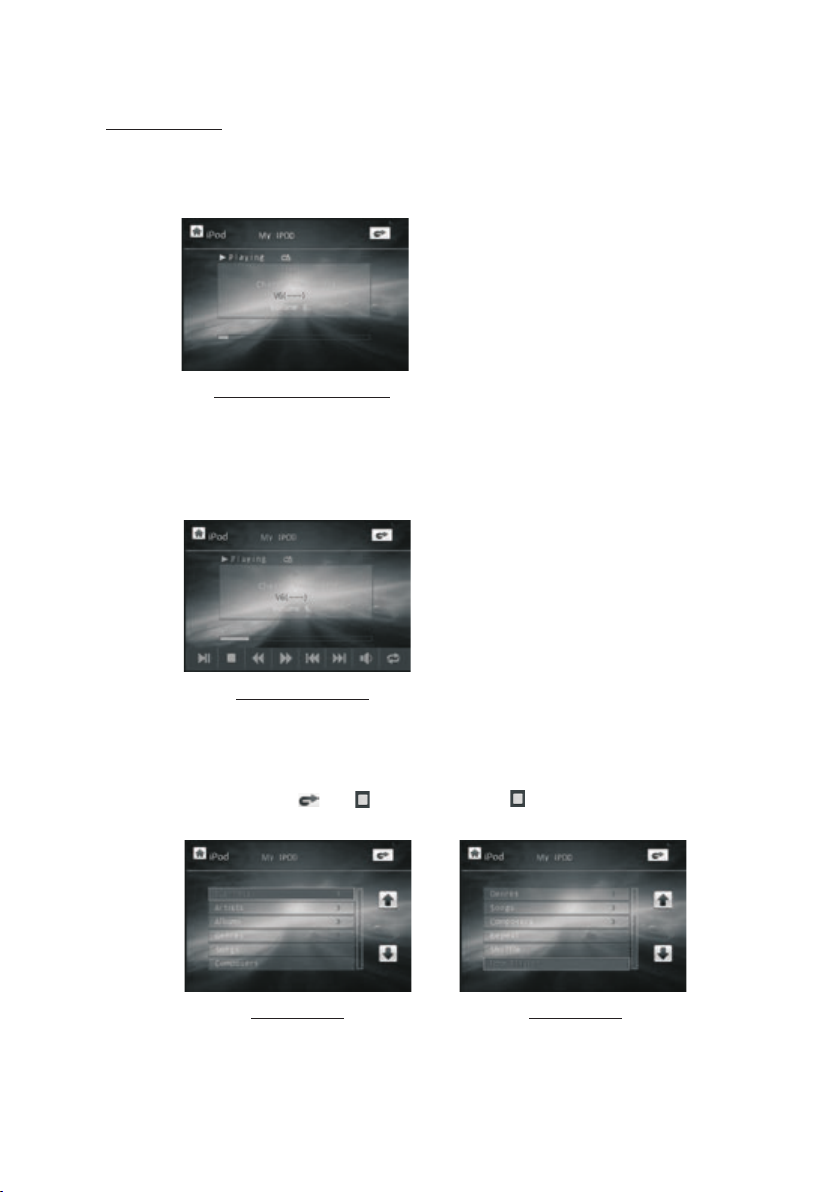
iPod Op era tion
1. Ente r iPo d mode
When in ser ting the iPo d plu g into an iPod , i t wil l enter iPod m ode a nd display t he
File Pl ayi ng interfa ce on t ouch scree n as fo llows:
The File P lay ing interfac e
You can als o use MODE button o r Mode Menu to ente r iPo d mode.
2. Popp ing up the Keyboa rd
In the Fi le Pl aying inte rfa ce, tappin g any p lace in the re cta ngle can pop u p the K ey board a s fol lows:
the iPod Keyb oar d
The functi ons o f the icons on t he iP od Keyboar d are s ame as ones of t he ic ons on the
Keybo ard o f disc/USB /ca rd.
3. Play a udi o files
Durin g pla yback, tap t he or i con or press t he bu tton to pop up t he iP od root
as foll ows :
the iPod root the iPod root
Use the v, ^ and OK b utt on or direct ly ta p one of the ite ms in t he rectang le to p lay a
desir ed fi le in the iPod .
Page 29

Tro uble Shooting
Please read the us er’s man ual c are ful ly before using the D VD pl aye r. If yo u have any troubles
in using this play er, tr y to so lve t he problems by t he su gge sti ons m entioned below. If y ou ca n
not remove th e tro ubl e aft er us ing all the sugg est ion s, pl eas e contact the co mpa ny or t he
technical serv ice c ent er au thorized by us. For t he sa ke of y our s afety, ple ase d o not o pen the
cover and repair t he pl aye r by yo urself, if tha t, it m ay ca use e lec tric shock.
NO PICTURE, S OUN D AND IN DIC ATION
* Ensure that t he po wer s wit ch is o n.
* Ensure that t he po wer c ord i s not d amaged or the fu se is n ot bl own .
* Ensure that t he po wer p lug i s con nected to the in let t igh tly.
NO SOUND BUT HAVE PICTURE
* Ensure that t he pl aye r’s a udi o out put h as a good connectio n wit h amp lif ier ’s au dio i nput.
* Check wheth er th e aud io co nne ctor is damaged.
* Check wheth er yo u hav e tur ned d own the volume.
* Ensure that y ou ha ve se t the r igh t AUDIO setup o f the p lay er.
* Ensure that t he au dio i s not u nde r muted.
NO PICTURE BU T HAVE SOUND
* Ensure that t he pl aye r’s v ide o out put h as a good connectio n wit h mon ito r’s v ide o inp ut.
* Ensure that y ou ha ve tu rne d you r monitor to the AV in put c hannel connecti ng to y our p lay er.
* Check wheth er th e vid eo co nne ctor is damaged.
* Ensure that y ou ha ve se t the r igh t VIDEO settin gs of t he pl aye r.
BLACK AND WHIT E PIC TUR E OR SC REE N ROLLING
* Ensure that y ou ha ve se t the r igh t TV SYS TEM ( e.g . PAL, NTSC) s ett ing .
FLAWS OF P ICTURE OR SOUND
* Check wheth er th e set tin g of AUD IO is right.
* Check wheth er th e dis c is sc rat ched or staine d.
* Check wheth er th e AV connector and th e out put t erm inal is stained.
* Check wheth er th ere i s con den sation inside the L ens . If so , lea ve the player of f for a n hour
or so, then try a gai n.
* Check wheth er th e ins tal lat ion angle is less tha n 30°.
DISPLAY NO DISC OR BAD DI SC
* Ensure that y ou ha ve pu t the d isc i n the unit.
* Check wheth er th e dis c is pu t in th e reverse side .
* Check wheth er th e dis c is di sto rted.
* Check wheth er th e dis c is st ain ed or scratche d bad ly.
* Ensure that t he di sc fo rma t is co mpatible to th e pla yer.
* Ensure that t he te mpe rat ure i nside the car is n ot to o hig h. If s o, cool off t ill t he am bie nt
temperatu re re tur ns to n orm al.
* Replace anothe r dis c to in ser t it into the disc c omp art men t.
REMOTE CONT ROL IS INSENSI TIV E OR DO ES NO T WORK
* Check the bat ter ies o f rem ote c ontrol and mak e sur e tha t the y are p owerful and ha ve
good conduc tiv ity.
* Direct the re mot e con tro l to th e IR sensor of the p lay er.
* Check wheth er th ere a re so me ob stacles betw een t he re mot e con trol and IR sens or.
SOME FUNCTI ON BU TTONS DO NOT WOR K
* Turn off th e pow er, th en turn on again.
* Reset the uni t to ze ro, t hen t urn o n again.
* Remove the fr ont p ane l fro m the u nit, then inst all i t aga in an d the n turn on again.
THE RADIO DOE S NOT W ORK
* Check wheth er th e ant enn a cab le is connected fir mly. Or manually tun e for a s tat ion .
Page 30

Specifi cation
General S pecification
Power Sup ply Requirement...... ............ ............ ............ ........DC 12V
Maximum Power O utput............4 x 80W(measured at DC 14.4 V)
Dimensions( w x h x d)............................. ........7”W x 2”H x 6.3”D
DVD Deck Sp ecification
Format. ............ ................... .....DVD/VCD /JPEG/MP4/MP 3/WMA/CD
Video S ystem.. ............ ......NTSC/PAL/PAL-M/PAL -N/AUTO(optional)
Audio Sys tem......... ................... ............ ............ ..........24 b it/96KH z
Loading S ystem.............. ............ ............ ............ ........ Au to Loading
Mountin g Angle............... ............ ............ ............ ............ ..0 to +/-3 0
Video S pecific ation
Video Type... ............ ............ ................... ............ .........16: 9 and 4:3
Video O utput lev el.......... ............ ............ ....Composite:1.0± 0.2 Vp-p
Load impedance : 75 ohms
Horizon tal Resolution....... ............ ............ ............ ................... ..500
Audio Spe cification
Audio Out put(Analog audio).... ............ ............ ............ ..2.0 -1.0Vrms
Frequen cy Response.......... ............ .......20Hz ~ 20 KHz(at 1KHz 0 dB)
S/N Ratio (Audio)............ ............ ............ .........≥90dB (at 1KHz 0 dB )
Separat ion......... ....... ............ ............ ............ ............ ..............50dB
+0
Radio Spe cification
FM Sectio n
Frequen cy range............. ............ ............ ..87.5MHz - 107. 9MHz(US )
87.5MHz - 108.0M Hz(EU)
Usable se nsitivity......... ............ ............ ................... ............ ......3uV
I.F Frequ ency.. ............ ............ ............ ............ ..................1 0.7MHz
AM Sectio n
Frequen cy.... ............ ............ ............ ............ 530KHz - 17 10KHz(US)
522KHz - 1620KHz (EU)
BOSS AUDIO CAR STEREOS CAR AUDIO SYSTEMS
 Loading...