

Acoustic Singer Live
ACS-LIVE
Owner’s Manual
Acoustic Amplier
Acoustic Singer Pro
ACS-PRO
Main Features
Acoustic Singer is an amp that’s designed to let the singer-instrumentalist perform powerfully on acoustic guitar and
vocals.
5 Independent mic and guitar channels are provided, and can be mixed.
5 A newly developed two-way speaker is bi-amped to deliver clear and powerful sound.
5 You can automatically add harmony to your vocal along with your guitar performance.
5 The mix of your vocal and guitar sound can be recorded and used for loop performances.
5 Independent eects are provided for the mic channel and guitar channel.
MIC channel Anti-feedback, delay/echo, reverb
GUITAR channel Acoustic resonance, anti-feedback, chorus reverb
5 A tweeter attenuator button is provided to deliver a milder sound.
5 An AUX input allows you to connect your audio player or other audio source, and the line output can be connected
to your PA system.
USING THE UNIT SAFELY
Before using this unit, carefully read the sections entitled “IMPORTANT SAFETY INSTRUCTIONS” (inside front cover), “USING THE UNIT
SAFELY” (p. 2), and “IMPORTANT NOTES” (p. 3). These sections provide important information concerning the proper operation of the unit.
Additionally, in order to feel assured that you have gained a good grasp of every feature of your new unit, read Owner’s Manual in its entirety.
This manual should be saved and kept on hand as a convenient reference.
Copyright © 2016 ROLAND CORPORATION
WARNING
About WARNING and CAUTION Notices
Used for instructions intended to alert the
user to the risk of death or severe injury
should the unit be used improperly.
Used for instructions intended to alert the
user to the risk of injury or material
damage should the unit be used
improperly.
* Material damage refers to damage or
other adverse effects caused with
respect to the home and all its
furnishings, as well to domestic animals
or pets.
ALWAYS OBSERVE THE FOLLOWING
WARNING
Make sure that the power cord is grounded
Connect mains plug of this model to a
mains socket outlet with a protective
earthing connection.
To completely turn o power to the unit, pull out
the plug from the outlet
Even with the power switch turned o, this
unit is not completely separated from its
main source of power. When the power
needs to be completely turned o, turn
o the power switch on the unit, then
pull out the plug from the outlet. For this reason, the
outlet into which you choose to connect the power
cord’s plug should be one that is within easy reach and
readily accessible.
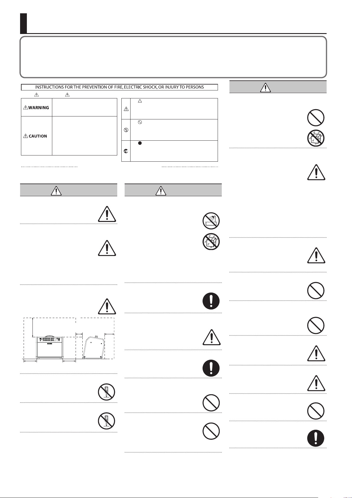
Secure a sucient amount of space at the setup
location
Since this unit normally emits a slight
amount of heat, make sure to secure
sucient space around it, as shown below.
Front Side
30 cm (12 in.)
or greater
20 cm (8 in.)
or greater
Do not disassemble or modify by yourself
Do not carry out anything unless you are
instructed to do so in the owner’s manual.
Otherwise, you risk causing malfunction.
Do not repair or replace parts by yourself
Refer all servicing to your retailer, the
nearest Roland Service Center, or an
authorized Roland distributor, as listed on
the “Information.”
5 cm (2 in.)
or greater
20 cm (8 in.)
or greater
15 cm (6 in.)
or greater
About the Symbols
The symbol alerts the user to important instructions or
warnings.The specific meaning of the symbol is
determined by the design contained within the triangle. In
the case of the symbol at left, it is used for general
cautions, warnings, or alerts to danger.
The symbol alerts the user to items that must never be
carried out (are forbidden). The specific thing that must
not be done is indicated by the design contained within
the circle. In the case of the symbol at left, it means that
the unit must never be disassembled.
The symbol alerts the user to things that must be
carried out. The specific thing that must be done is
indicated by the design contained within the circle. In the
case of the symbol at left, it means that the power-cord
plug must be unplugged from the outlet.
WARNING
Do not use or store in the following types of
locations
• Subject to temperature extremes (e.g.,
direct sunlight in an enclosed vehicle,
near a heating duct, on top of heatgenerating equipment); or are
• Damp (e.g., baths, washrooms, on wet
oors); or are
• Exposed to steam or smoke; or are
• Subject to salt exposure; or are
• Exposed to rain; or are
• Dusty or sandy; or are
• Subject to high levels of vibration and shakiness;
or are
• Placed in a poorly ventilated location.
Do not place in an unstable location
Otherwise, you risk injury as the result of
the unit toppling over or dropping down.
Connect the power cord to an outlet of the correct
voltage
The unit should be connected to a power
supply only of the type described as
marked on the rear side of unit.
Use only the supplied power cord
Use only the attached power cord. Also,
the supplied power cord must not be used
with any other device.
Do not bend the power cord or place heavy objects
on it
Otherwise, re or electric shock may result.
Avoid extended use at high volume
Use of the unit at high volume for
extended periods of time may cause
hearing loss. If you ever experience any
hearing loss or ringing in the ears, you
should immediately stop using the unit
and consult a specialized physician.
Do not allow foreign objects or liquids to enter
unit; never place containers with liquid on unit
Do not place containers containing liquid
(e.g., ower vases) on this product. Never
allow foreign objects (e.g., ammable
objects, coins, wires) or liquids (e.g., water
or juice) to enter this product. Doing so
may cause short circuits, faulty operation,
or other malfunctions.
Turn o the unit if an abnormality or malfunction
occurs
Immediately turn the unit o, remove the
power cord from the outlet, and request
servicing by your retailer, the nearest
Roland Service Center, or an authorized
Roland distributor, as listed on the
“Information” when:
• The power cord has been damaged; or
• If smoke or unusual odor occurs; or
• Objects have fallen into, or liquid has been spilled
onto the unit; or
• The unit has been exposed to rain (or otherwise has
become wet); or
• The unit does not appear to operate normally or
exhibits a marked change in performance.
Be cautious to protect children from injury
Always make sure that an adult is on hand
to provide supervision and guidance when
using the unit in places where children
are present, or when a child will be using
the unit.
Do not drop or subject to strong impact
Otherwise, you risk causing damage or
malfunction.
Do not share an outlet with an unreasonable
number of other devices
Otherwise, you risk overheating or re.
Do not use overseas
Before using the unit in overseas, consult
with your retailer, the nearest Roland
Service Center, or an authorized Roland
distributor, as listed on the “Information.”
The ventilation should not be impeded by covering
the ventilation openings with items such
as newspaper, table-cloths, curtains etc.
No naked ame sources such as lighted candles should
be placed on the apparatus.
Use the apparatus in moderate climates.
2
IMPORTANT NOTES
CAUTION
When disconnecting the power cord, grasp it by the
plug
To prevent conductor damage, always
grasp the power cord by its plug when
disconnecting it.
Periodically clean the power plug
An accumulation of dust or foreign objects
between the power plug and the power
outlet can lead to re or electric shock.
At regular intervals, be sure to pull out
the power plug, and using a dry cloth,
wipe away any dust or foreign objects that may have
accumulated.
Disconnect the power plug whenever the unit will
not be used for an extended period of time
Fire may result in the unlikely event that a
breakdown occurs.
Route all power cords and cables in such a way as
to prevent them from getting entangled
Injury could result if someone were to
trip on a cable and cause the unit to fall
or topple.
CAUTION
Avoid climbing on top of the unit, or placing heavy
objects on it
Otherwise, you risk injury as the result of
the unit toppling over or dropping down.
Never connect/disconnect a power plug if your
hands are wet
Otherwise, you could receive an electric
shock.
Disconnect all cords/cables before moving the unit
Before moving the unit, disconnect the
power plug from the outlet, and pull out all
cords from external devices.
Before cleaning the unit, disconnect the power
plug from the outlet
If the power plug is not removed from the
outlet, you risk receiving an electric shock.
CAUTION
Whenever there is a threat of lightning, disconnect
the power plug from the outlet
If the power plug is not removed from the
outlet, you risk causing malfunction or
receiving an electric shock.
Precautions concerning use of phantom power
supply
Always turn the phantom power o
when connecting any device other than
condenser microphones that require
phantom power. You risk causing damage
if you mistakenly supply phantom power
to dynamic microphones, audio playback devices, or
other devices that don’t require such power. Be sure to
check the specications of any microphone you intend
to use by referring to the manual that came with it.
(This instrument’s phantom power: 48 V DC, 14 mA
Max)
Do not remove the speaker grille and speaker
Do not remove the speaker grille and
speaker by any means. Speaker is not user
replaceable. Shock hazardous voltages and
currents are present inside the enclosure.
IMPORTANT NOTES
Power Supply
• Do not connect this unit to same electrical outlet
that is being used by an electrical appliance that
is controlled by an inverter or a motor (such as a
refrigerator, washing machine, microwave oven, or
air conditioner). Depending on the way in which
the electrical appliance is used, power supply noise
may cause this unit to malfunction or may produce
audible noise. If it is not practical to use a separate
electrical outlet, connect a power supply noise lter
between this unit and the electrical outlet.
Placement
• Using the unit near power ampliers (or other
equipment containing large power transformers)
may induce hum. To alleviate the problem, change
the orientation of this unit; or move it farther away
from the source of interference.
• This unit may interfere with radio and television
reception. Do not use this unit in the vicinity of such
receivers.
• Noise may be produced if wireless communications
devices, such as cell phones, are operated in the
vicinity of this unit. Such noise could occur when
receiving or initiating a call, or while conversing.
Should you experience such problems, you should
relocate such wireless devices so they are at a
greater distance from this unit, or switch them o.
• Do not allow lighting devices that normally are used
while their light source is very close to the unit (such
as a piano light), or powerful spotlights to shine
upon the same area of the unit for extended periods
of time. Excessive heat can deform or discolor the
unit.
• When moved from one location to another where
the temperature and/or humidity is very dierent,
water droplets (condensation) may form inside
the unit. Damage or malfunction may result if you
attempt to use the unit in this condition. Therefore,
before using the unit, you must allow it to stand for
several hours, until the condensation has completely
evaporated.
• Do not paste stickers, decals, or the like to this
instrument. Peeling such matter o the instrument
may damage the exterior nish.
• Depending on the material and temperature of the
surface on which you place the unit, its rubber feet
may discolor or mar the surface.
• Do not place containers or anything else containing
liquid on top of this unit. Also, whenever any liquid
has been spilled on the surface of this unit, be sure
to promptly wipe it away using a soft, dry cloth.
Maintenance
• To clean the unit, use a dry, soft cloth; or one that
is slightly dampened. Try to wipe the entire surface
using an equal amount of strength, moving the
cloth along with the grain of the wood. Rubbing too
hard in the same area can damage the nish.
• Never use benzine, thinners, alcohol or solvents of
any kind, to avoid the possibility of discoloration
and/or deformation.
Repairs and Data
• Before sending the unit away for repairs, be sure to
make a backup of the data stored within it; or you
may prefer to write down the needed information.
Although we will do our utmost to preserve the
data stored in your unit when we carry out repairs,
in some cases, such as when the memory section
is physically damaged, restoration of the stored
content may be impossible. Roland assumes no
liability concerning the restoration of any stored
content that has been lost.
Additional Precautions
• Roland assumes no liability concerning the
restoration of any stored content that has been lost.
• Use a reasonable amount of care when using the
unit’s buttons, sliders, or other controls; and when
using its jacks and connectors. Rough handling can
lead to malfunctions.
• When disconnecting all cables, grasp the connector
itself—never pull on the cable. This way you will
avoid causing shorts, or damage to the cable’s
internal elements.
• A small amount of heat will radiate from the unit
during normal operation.
• To avoid disturbing others nearby, try to keep the
unit’s volume at reasonable levels.
• Do not use connection cables that contain a built-in
resistor.
Intellectual Property Right
• It is forbidden by law to make an audio recording,
video recording, copy or revision of a third party’s
copyrighted work (musical work, video work,
broadcast, live performance, or other work), whether
in whole or in part, and distribute, sell, lease,
perform or broadcast it without the permission of
the copyright owner.
• Do not use this product for purposes that could
infringe on a copyright held by a third party. We
assume no responsibility whatsoever with regard to
any infringements of third-party copyrights arising
through your use of this product.
• Roland and BOSS are either registered trademarks
or trademarks of Roland Corporation in the United
States and/or other countries.
• ASIO is a trademark and software of Steinberg Media
Technologies GmbH.
• This product contains eParts integrated software
platform of eSOL Co.,Ltd. eParts is a trademark of
eSOL Co., Ltd. in Japan.
• Company names and product names appearing
in this document are registered trademarks or
trademarks of their respective owners.
3
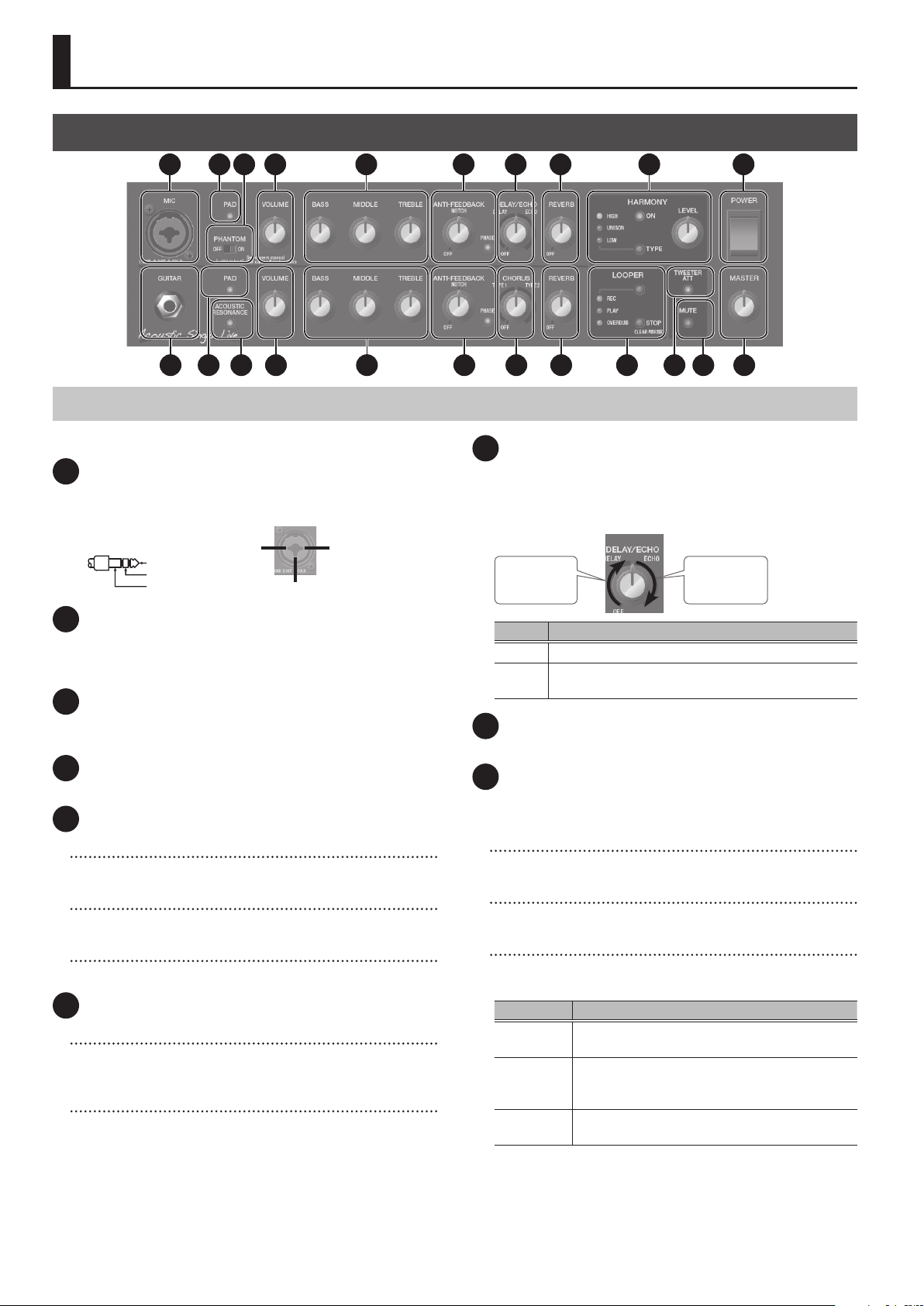
Panel Description
1: GND2: HOT
1: GND 2: HOT
RING: COLD
Front Panel
1 65 92 3 214 7 8
10 15 181411 1912 20 2213 16 17
Mic Channel (Upper Row)
This is the channel for connecting a vocal mic.
1 MIC jack
Connect your mic here.
* Pin assignment of MIC jack
TIP: HOT
SLEEVE: GND
2: HOT 1: GND
3: COLD
2 [PAD] button
Use this if the input level of the MIC jack is excessive, or if the
sound is distorted. When the button is pressed, the input level is
attenuated by 15 dB, and the button is lit green.
3 [PHANTOM] switch
Supplies phantom power. Turn this ON if you connect a condenser
mic that requires a phantom power supply.
4 [VOLUME] knob
Adjusts the volume.
5 EQUALIZER
[BASS] knob
Adjusts the sound level of the low-frequency range.
[MIDDLE] knob
Adjusts the sound level of middle-frequency range.
[TREBLE] knob
Adjusts the sound level of the high-frequency range.
6 ANTI-FEEDBACK
[PHASE] button
If acoustic feedback is a problem, rst try pressing the [PHASE]
button. Switching the phase will help suppress acoustic feedback.
[NOTCH] knob
If turning on the [PHASE] button does not help, adjust the
[NOTCH] knob.
5 While acoustic feedback is occurring, turn the [NOTCH]
(frequency) knob to nd the location at which feedback is
suppressed.
5 Turning the knob toward the right suppresses feedback at a
higher frequency; turning the knob toward the left suppresses
feedback at a lower frequency.
4
7 [DELAY/ECHO] knob
Applies delay/echo to the audio that is input from the MIC jack.
Turn the knob to adjust the depth of the eect.
* Either DELAY or ECHO is selected depending on the position of
the knob.
DELAY
depth
Type Eect
DELAY Produces an echo-like eect.
ECHO
Produces a distinctively spacious eect similar to a
tape echo unit.
ECHO
depth
8 [REVERB] knob
Adjusts the reverb depth.
9 HARMONY
Lets you add natural harmony to the audio that is input from the
MIC jack.
[LEVEL] knob
Adjusts the volume of the harmony.
[ON] button
Switches HARMONY on/o.
[TYPE] button
Selects the type of harmony. The type switches each time you
press the button.
Type Explanation
HIGH
UNISON
LOW
* You can specify the reference pitch used when the harmony
is added. For details, refer to “Specifying the Harmony
Reference Pitch” (p. 8).
Adds harmony above the vocal sound that is
input.
Simulates the doubling eect produced when a
vocalist records the same melody a second time,
adding richness to the sound.
Adds harmony below the vocal sound that is
input.

Panel Description
Guitar Channel (Lower Row)
This is the channel for connecting a guitar, such as an acousticelectric guitar.
10 GUITAR jack
Connect your guitar here. You can connect any guitar that is
equipped with a pickup.
11 [PAD] button
Use this if the input level of the GUITAR jack is excessive. When the
button is pressed, the input level is attenuated by 10 dB, and the
button is lit green.
12 [ACOUSTIC RESONANCE] button
Adds the natural resonance of an acoustic guitar.
The setting changes in the following order each time you press
the button.
Button Explanation
Green A full sound with emphasized body resonance
Orange A bright sound with boosted mid-range resonance
Red A brilliant sound extending to the high range
Unlit O
13 [VOLUME] knob
Adjusts the volume.
14 EQUALIZER
[BASS] knob
Adjusts the sound level of the low-frequency range.
[MIDDLE] knob
Adjusts the sound level of middle-frequency range.
[TREBLE] knob
Adjusts the sound level of the high-frequency range.
16 [CHORUS] knob
Applies a chorus eect to the sound that is input from the GUITAR
jack. Turn the knob to adjust the depth of the eect.
* Either TYPE1 or TYPE2 is selected depending on the position of
the knob.
TYPE1
depth
Type Eect
TYPE1 Chorus with natural modulation.
TYPE2 Chorus with emphasized modulation.
TYPE2
depth
17 [REVERB] knob
Adjusts the reverb depth.
18 LOOPER
You can record up to 40 seconds (MONO) of a performance
and play back the recorded section over and over. You can also
layer additional performances with the recording as it plays
back (overdubbing). This lets you create real-time backing
performances on the y.
* For more about how to operate the looper, refer to “Using the
Looper” (p. 9).
[LOOPER] button
Switches between recording, loop playback, and overdubbing.
[STOP] button
Stops recording or playback.
REC/PLAY/OVERDUB indicator
Indicates the status of the looper.
Common to Both Channels
15 ANTI-FEEDBACK
[PHASE] button
If acoustic feedback is a problem, rst try pressing the [PHASE]
button. Switching the phase will help suppress acoustic feedback.
[NOTCH] knob
If turning on the [PHASE] button does not help, adjust the
[NOTCH] knob.
5 While acoustic feedback is occurring, turn the [NOTCH]
(frequency) knob to nd the location at which feedback is
suppressed.
5 Turning the knob toward the right suppresses feedback at a
higher frequency; turning the knob toward the left suppresses
feedback at a lower frequency.
19 [TWEETER ATT] button
Applies a lter to the high-frequency region, making the sound
milder. If this is on, the button is lit green. This is eective in cases
such as when you want the guitar strings to sound softer and
more natural.
20 [MUTE] button
You can mute the sound while leaving the unit powered-on. This
lets you mute the amp without changing the volume or other
settings when you leave the stage, such as between sets of your
live performance.
* The sound of the PHONES/REC OUT jack is not muted.
* The sound from the AUX jack that is output to the DI/LINE OUT
jacks is not muted.
21 [POWER] switch
Turns the power of the Acoustic Singer on/o.
22 [MASTER] knob
Adjusts the overall volume.
5

Panel Description
Rear Panel
1 632
5
* To prevent malfunction and equipment failure, always turn down the
volume, and turn o all the units before making any connections.
1 AC IN jack
Connect the included power cord.
* Use only the power cord that was included with the unit.
2 DI/LINE OUT
Connect this to your PA system or recorder.
You can use this in conjunction with an external PA system, or
to record your performance via direct line while monitoring the
sound from this unit.
Adjust the output level using the [VOLUME] knob of each
channel.
MIC/MIX jack
From this jack, the audio that is input from the MIC jack can be
output by itself, or mixed with the audio that is input from the
GUITAR jack.
GUITAR/MIX jack
From this jack, the audio that is input from the GUITAR jack can
be output by itself, or mixed with the audio that is input from the
MIC jack.
* Pin assignment of MIC/MIX jack
and GUITAR/MIX jack
[OUT SELECT] switch
1: GND 2: HOT
3: COLD
4
4 REC OUT
You can use a commercially available USB 2.0 cable to record the
sound of the Acoustic Singer into your computer.
You must install the USB driver when connecting the unit to
your computer.
Download the USB driver from the BOSS website. For details, refer
to Readme.htm which is included in the download.
www.boss.info/support/
O
jack
Species the output of the MIC/MIX jack and GUITAR/MIX jack.
Setting Explanation
The inputs from the MIC jack and the GUITAR jack
MIX
POST EFX
DI
pass through the eects of the respective channel,
and are then mixed and output. The input from the
AUX jack is also mixed and output.
The inputs from the MIC jack and the GUITAR jack
pass through the eects of the respective channel,
and are then output separately from the MIC/MIX
jack and the GUITAR/MIX jack.
The inputs from the MIC jack and GUITAR jack
do not pass through the eects, but are output
separately from the MIC/MIX jack and the GUITAR/
MIX jack.
3 PHONES/REC OUT jack
Connect headphones here. To adjust the volume, use the
[VOLUME] knob along with the [MASTER] knob.
* If a plug is inserted in this jack, no sound will be output from
the Acoustic Singer’s own speaker. This is convenient if you
don’t want loud sound to be produced from the speaker, such
as when you’re practicing at night.
6

Panel Description
1: GND2: HOT
1: GND 2: HOT
5 FOOT CONTROL
If you connect a footswitch (sold separately: BOSS FS-6, FS-7, or
FS-5U), you can use your foot to control LOOPER operations (p. 9)
or turn CHORUS, HARMONY, and MUTE on/o.
* Pin assignment of LOOPER/CHORUS jack, HARMONY/MUTE
jack, and GA-FC jack.
Rear Panel
Stereo 1/4” phone type
Stereo 1/4” phone type
or
FS-6 FS-7
RING TIP
RING
Stereo 1/4” phone type
1/4” phone type x 2
or
FS-5U
RING
TIP
TIP
RING
SLEEVE (GND)
TIP
Using the GA-FC
You can switch on/o the REVERB of each channel, DELAY/ECHO,
HARMONY, and MUTE.
Ax the included adhesive labels to the GA-FC.
Using the expression pedals
If you connect an expression pedal (sold separately: Roland EV-5,
BOSS FV-500L, BOSS FV-500H), you can use the pedal to vary
the volume of the guitar channel or control the volume of the
HARMONY eect.
* Use only the specied expression pedal. By connecting any
other expression pedals, you risk causing malfunction and/or
damage to the unit.
GA-FC
If connected to the LOOPER/CHORUS jack
Switch Explanation
TIP LOOPER Operates LOOPER (p. 9).
RING CHORUS Turns CHORUS (p. 5) on/o.
If connected to the HARMONY/MUTE jack
Switch Explanation
TIP HARMONY Turns HARMONY (p. 4) on/o.
RING MUTE Turns MUTE (p. 5) on/o.
GA-FC jack
You can connect a GA-FC (sold separately) and turn on/o the
following.
DELAY/ECHO and REVERB of the mic channel,
CHORUS and REVERB of the guitar channel.
HARMONY, MUTE
Connecting the GA-FC
Connect a stereo cable to the GA-FC jack.
* Always use a stereo cable.
Expression Pedal
Jack Explanation
GTR VOL. Adjusts the volume of the guitar channel.
HARMONY LEV. Controls the HARMONY volume.
Setting MINIMUM VOLUME of an expression pedal
With the [MINIMUM VOLUME]
knob of an expression pedal,
you can set the value for when
the pedal is lifted up all the way
(lowest value).
[MINIMUM
VOLUME]
knob
6 AUX
You can connect a CD player, audio player, or electronic musical
instrument, and hear it play along with your own performance.
INPUT jack
Connect your CD player, audio player, or electronic musical
instrument here.
[LEVEL] knob
Adjusts the volume of the connected instrument.
GA-FC
7

Panel Description
Turning the Power On/O
* Once everything is properly connected (p. 6), be sure to follow
the procedure below to turn on their power. If you turn on
equipment in the wrong order, you risk causing malfunction or
equipment failure.
1. Make sure that the Acoustic Singer’s [MASTER]
knob and the volume of the devices connected to
the Acoustic Singer are set to 0.
2. Turn on the Acoustic Singer.
* Before turning the unit on/o, always be sure to
turn the volume down. Even with the volume
turned down, you might hear some sound when
switching the unit on/o. However, this is normal
and does not indicate a malfunction.
3. Turn on the power of the devices
connected to the LINE OUT jack,
PHONES jack, and REC OUT O port.
4. Use each channel’s [VOLUME] knob and [MASTER]
knob to adjust the volume of the Acoustic Singer.
5. Adjust the volume levels for the connected devices.
Before switching o the power, lower the volume on each of the
devices in your system and then TURN OFF the devices in the
reverse order to which they were switched on.
* If you need to turn o the power completely, rst turn o the
unit, then unplug the power cord from the power outlet. Refer
to “To completely turn o power to the unit, pull out the
plug from the outlet” (p. 2).
Specifying the Harmony Reference Pitch
Here’s how to specify the reference pitch that is used when adding
harmony. Match this reference pitch to the tuning of your guitar
or other accompaniment instrument.
1. Long-press the [TYPE] button.
The Acoustic Singer is in harmony reference
pitch setting mode.
2. Use the [TYPE] button to select a
reference pitch.
Each time you press the button, you’ll cycle
through the following settings in the order of 1–7.
Indicator Explanation
1 UNISON lit 440 Hz (factory setting)
2 UNISON+HIGH lit 441 Hz
3 UNISON+HIGH blinking 442 Hz
4 HIGH blinking 443 Hz
5 UNISON+LOW lit 439 Hz
6 UNISON+LOW blinking 438 Hz
7 LOW blinking 437 Hz
3. Long-press the [TYPE] button to exit reference
pitch setting mode.
* This setting is remembered even when the
power is switched o. When you switch on the
power and enter reference pitch setting mode,
the currently specied setting (1–7 listed
above) is shown.
8

Using the Looper
Panel Description
Record-standby
Press the [LOOPER] button
to enter record-standby
mode.
Record
When audio is input,
recording starts immediately.
At the point where you want
to loop, press the [LOOPER]
button to playback.
REC/PLAY/OVERDUB indicator status
Loop Playback
Play back the loop.
Pressing the [LOOPER]
button will switch to
overdubbing.
Stop/Clear
To stop, press the [STOP]
button.
To clear the phrase, hold
down the [STOP] button for
at least two seconds while
stopped.
Overdub
Record additional layers
while playing back the
loop.
Press the [LOOPER] button
to switch to playback.
Indicator Explanation
REC Blinking while in record-standby, lit while recording.
PLAY Lit while playing back.
OVERDUB Lit while overdubbing.
Looper operations using a footswitch
You can also operate the looper by using a footswitch (sold
separately: FS-5U, FS-6, FS-7).
5 If a footswitch is connected, recording starts not when audio
is input but when you press the footswitch (TIP). Playback
and overdubbing operations are the same as when using the
[LOOP] button.
5 If you press the footswitch (TIP) twice within one second, the
looper stops.
5 If you hold down the footswitch (TIP) for two seconds or longer,
the phrase is cleared.
9

Main Specications
BOSS Acoustic Singer Pro: Acoustic Amp
BOSS Acoustic Singer Live: Acoustic Amp
Acoustic Singer Live Acoustic Singer Pro
Rated Power
Output
Nominal Input
Level
Speaker
Connectors
Power
Consumption
Dimensions
Weight
Accessories
60 W (Woofer: 50 W, Tweeter: 10 W) 120 W (Woofer: 100 W, Tweeter: 20 W)
MIC INPUT: -33 dBu (2.5 k Ω)
GUITAR INPUT: -10 dBu (5 M Ω)
AUX INPUT: -8 dBu (10 k Ω)
16 cm (6.5 inches) Woofer x 1, 2.5 cm
(1 inch) Dome Tweeter x 1
MIC jack: Combo type (XLR, 1/4-inch TRS phone type)
GUITAR jack: 1/4-inch phone type
AUX IN jack: Stereo miniature phone type
PHONES/REC OUT jack: Stereo 1/4-inch phone type
DI/LINE OUT MIC/MIX jack: XLR type
DI/LINE OUT GUITAR/MIX jack: XLR type
FOOT CONTROL LOOPER/CHORUS jack: 1/4-inch TRS phone type
FOOT CONTROL HARMONY/MUTE jack: 1/4-inch TRS phone type
GA-FC jack: 1/4-inch TRS phone type
USB port: USB B type
AC IN jack
40 W 50 W
367 (W) x 274 (D) x 314 (H) mm
14-1/2 (W) x 10-13/16 (D) x 12-3/8 (H)
inches
10.5 kg
23 lbs 3 oz
Owner’s manual
Power cord
GA-FC sticker
20 cm (8 inches) Woofer x 1, 2.5 cm
(1 inch) Dome Tweeter x 1
417 (W) x 330 (D) x 358 (H) mm
16-7/16 (W) x 13 (D) x 14-1/8 (H)
inches
14.5 kg
32 lbs oz
* 0 dBu = 0.775 Vrms
* This document explains the specications of the product at the
time that the document was issued. For the latest information,
refer to the Roland website.
10

Block Diagram
USB
HPF
TW
MUTE
MASTER
TW
WF
LPF
ATT
LOOPER
PHONES
HA
MIX OUT
DI/LINE OUT
MIC/MIX
LA
DI
POST EFX
MIC
The sound of the
AUX is not muted
OUT SELECT
DI
MIX
GUITAR/MIX
LA
MIX
POST EFX
GUITAR
FOOT
LOOPER: REC/PLAY/OVERDUB/
STOP/CLEAR (tip)
CHORUS (ring)
HARMONY (tip)
CONTROL
GA-FC
MUTE (ring)
MIC: DELAY/ECHO, REVERB
GTR: CHORUS, REVERB
HARMONY, MUTE
HARMONY LEVEL (Expression pedal)
GTR volume (Expression pedal)
DELAY/ECHO,
REVERB
EQ
HARMONY
AFB
VOLUME
PAD
PRE AMP
-15dB
PHANTOM
+48V
POST FX OUT
DI OUT
CHORUS,
REVERB
EQ
ACOUSTIC
RESONANCE
AFB
VOLUME
PAD
-10dB
PRE AMP
VOLUME
PRE AMP
L
R
MIC
1 : GND
2 : HOT
3 : COLD
GUITAR
AUX
 Loading...