

Page 1

Bose
®
Home Theater Speakers
®
Center Speaker
Speaker System
Owner’s Guide
AM257528_01_V.pdf
VCS-30
VCS-10
®
Series II Center/Surround
October 26, 2001
Page 2
Declaration of Conformity
We, the offerer,
Bose Corporation, The Mountain
Framingham, MA 01701-9168 USA
acknowledge our sole responsibility, that the product,
Kind of equipment: Loudspeakers
Type designation: VCS-10
®
, VCS-30® II
in accordance with EMC directive 89/336/EC and article 10(1) of the
Directive, is in compliance with the following norm(s) or document(s):
Technical regulations: EN 50081-1, EN 50082-1
Accredited by Bose Corporation
1 May 2001
Bose Products B.V. Nic Merks,
Nijverheidstraat 8, Vice President, Bose Europe
1135 GE Edam, Manufacturer’s authorized
The Netherlands EU representative
2 October 26, 2001 AM257528_01_V.pdf
Page 3

Where to find …
Setting Up . . . . . . . . . . . . . . . . . . . . . . . . . . . . . . . . . . . . . . . 4
Adjusting Your Surround Sound Settings . . . . . . . . . . . . . . . 12
Reference . . . . . . . . . . . . . . . . . . . . . . . . . . . . . . . . . . . . . . . . 14
Before you begin . . . . . . . . . . . . . . . . . . . . . . . . . . . . . . . 4
Unpack the carton . . . . . . . . . . . . . . . . . . . . . . . . . . . . . . 4
Place the center speaker . . . . . . . . . . . . . . . . . . . . . . . . . 6
Position your surround speakers . . . . . . . . . . . . . . . . . . . 7
Connect the speakers . . . . . . . . . . . . . . . . . . . . . . . . . . . 8
Choosing speaker cord . . . . . . . . . . . . . . . . . . . . . . . 8
Be sure to use the cord properly . . . . . . . . . . . . . . . 8
Make the connections . . . . . . . . . . . . . . . . . . . . . . . . 9
Check the connections . . . . . . . . . . . . . . . . . . . . . . . . . . 10
Mounting your speakers on a wall . . . . . . . . . . . . . . . . . . 11
For realistic home theater sound . . . . . . . . . . . . . . . . . . . 12
How to set your Pro-Logic receiver . . . . . . . . . . . . . . . . . 12
To use the test tone . . . . . . . . . . . . . . . . . . . . . . . . . 12
To balance the bass and treble . . . . . . . . . . . . . . . . . 12
How to set your Dolby Digital receiver . . . . . . . . . . . . . . 13
If the sound is interrupted . . . . . . . . . . . . . . . . . . . . . . . . 13
Troubleshooting . . . . . . . . . . . . . . . . . . . . . . . . . . . . . . . . 14
Customer service . . . . . . . . . . . . . . . . . . . . . . . . . . . . . . . 14
Cleaning speakers . . . . . . . . . . . . . . . . . . . . . . . . . . . . . . 15
Warranty period . . . . . . . . . . . . . . . . . . . . . . . . . . . . . . . . 15
Technical information . . . . . . . . . . . . . . . . . . . . . . . . . . . 15
For your records
Serial numbers are located on the back of each speaker.
Center speaker serial number: _____________________________________
Surround speaker serial numbers: _______________and _______________
Dealer name: ____________________________________________________
Dealer phone: _________________ Purchase date: ____________________
We suggest you keep your sales receipt and warranty card together with
this owner’s guide.
©2001 Bose Corporation. No part of this work may be reproduced, modified,
distributed or otherwise used without prior written permission.
Dolby is a trademark of Dolby Laboratories Licensing Corporation.
AM257528_01_V.pdf October 26, 2001 3
Page 4

Setting Up
Before you begin
Thank you for choosing Bose
VCS-10
round speaker system are engineered specifically for use with
video soundtracks. They are designed to make the most of audio
for video (A/V) surround sound receivers or amplifiers with five
amplified speaker outputs.
In either package you purchased, there is a center speaker. Its
magnetic shielding allows you to put this speaker directly on,
above, or below your video screen without causing screen discoloration. There it will deliver clear, crisp soundtrack reproduction
from the center channel. Other speakers at the front of your room
provide the left and right video sound.
In additon to one center speaker, the VCS-30 Series II system
includes two surround speakers. They are designed for use at the
rear of your room. Advanced design brackets included in this
package make the surround speakers simple to mount on a wall.
Please read and follow the instructions in this guide. They will help
you set up and use your new home theater speakers for the fullest
listening and viewing enjoyment.
®
®
center speaker and the VCS-30
home theater speakers. Both the
®
Series II center/sur-
Unpack the carton
Carefully unpack the carton and save all packing materials for
possible future use. Inspect the contents (Figure 1, A or B).
If any speaker appears damaged, do not use it. Instead, repack all
parts in the original carton and notify Bose or your authorized
Bose dealer immediately.
Note: Now is a good time to record the serial numbers found on
the back of each speaker. Write them on your warranty card and
on page 3 of this owner’s guide.
4 October 26, 2001 AM257528_01_V.pdf
Page 5
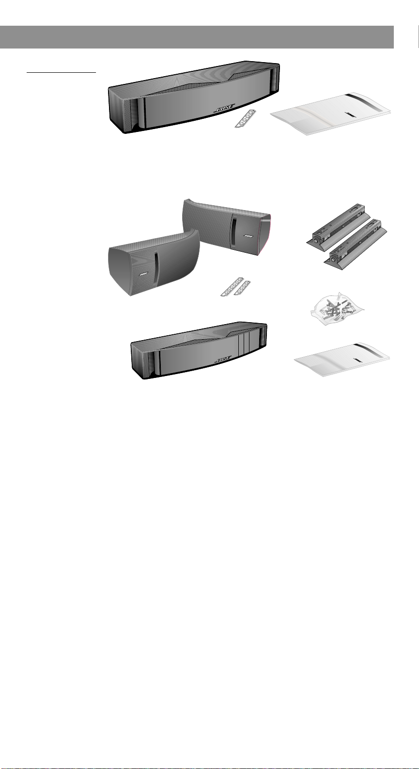
Figure 1
Center speaker
Owner’s guide
Rubber feet
Center speaker
Rubber
feet
Left surround
speaker
Owner’s guide
Mounting hardware
Mounting
brackets
Right surround speaker
The VCS-10
speaker carton
contents
A.
B
Setting Up
®
. The VCS-30
Series II system
carton contents
®
AM257528_01_V.pdf October 26, 2001 5
Page 6
Pre-attached
feet (2 of 6)
Optional self-adhesive feet
(4 supplied)
Setting Up
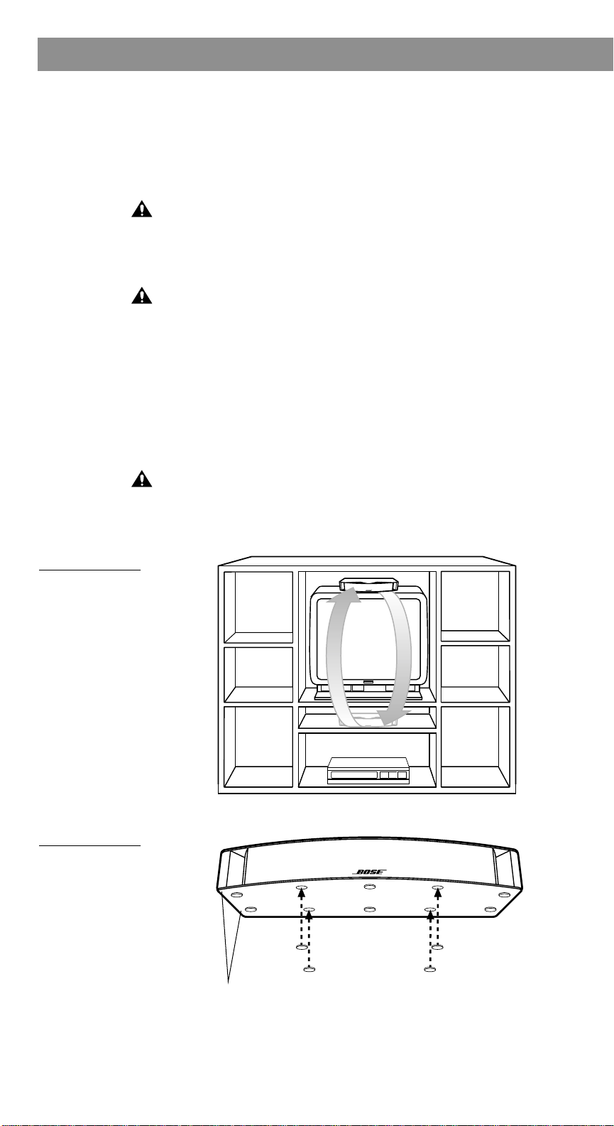
Place the center speaker
The center speaker provides center channel surround sound performance while taking up very little space. The slim, low-profile
design allows it to fit directly on, above, or below your television
(Figure 2). Rubber feet ensure stable positioning and magnetic
shielding prevents video screen discoloration.
CAUTION: The VCS-10
in a vertical position, mounted on a wall, or to support the additional weight of items placed on top of the speaker, which could
also hamper its performance. Do not allow debris or water from
plants, or other items on a shelf above, to fall on the speaker.
CAUTION: Do not install near any heat sources, such as radia-
tors, heat registers, stoves, or other apparatus (including amplifiers) that produce heat.
For full enjoyment, follow these placement guidelines:
• Place the speaker on, or very close to, your television set and
center it with the screen.
• Be sure to set it on a level surface.
• Apply additional rubber feet farther in from the edges, as
needed, for greater stability (Figure 3).
CAUTION: Be sure the center speaker is in a stable position and
does not extend beyond the edges of its support. Use additional
rubber feet as needed to prevent it from tipping or falling from a
television surface that is not completely level.
®
speaker is not designed to be set on end
Figure 2
Alternate choices
for placing the
center speaker
Figure 3
Adding optional
self-adhesive feet
to the bottom of
the center speaker
6 October 26, 2001 AM257528_01_V.pdf
Page 7
Surround speakers
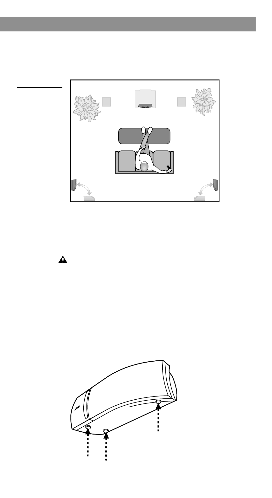
Position your surround speakers
Surround speakers in the VCS-30
vide surround sound effects from the rear of your viewing area
(Figure 4).
Figure 4
Alternate choices
for placing the
surround speakers
Setting Up
®
Series II speaker system pro-
Figure 5
Applying selfadhesive feet to
the bottom of a
surround speaker
Brackets that come with these speakers allow you to mount them
on the wall. If you use the supplied brackets, refer to the bracket
instruction diagrams in the Appendix. Do not connect the speakers before reviewing those instructions.
If you prefer, set the speakers on a table or shelf in a horizontal
position.
CAUTION: Do not install near any heat sources, such as radia-
tors, heat registers, stoves, or other apparatus (including amplifiers) that produce heat.
For accurate surround sound:
• Place these speakers behind the general viewing area, along the
rear wall or to the rear of side walls.
• Place both speakers at the same height.
• Place the speakers as far apart as your room allows.
• To mount the speakers on brackets, be sure to leave room
between the end of the bracket and the wall for tightening the
bracket screw.
AM257528_01_V.pdf October 26, 2001 7
Page 8

Setting Up
Connect the speakers
CAUTION: Before making any connections, turn off your receiver
or amplifier and unplug it from the AC power (mains) outlet. Not
doing so may result in damage to your system.
CAUTION: Never use broken or frayed wiring, which can result in
damage to your components.
Note: Before running speaker cord through a wall or under a floor,
check your local building code requirements and safety regulations. You may want to contact an electrical installer for this information.
If your receiver’s center channel is not amplified, you must connect an amplifier to the receiver. Use an RCA cable to connect the
center channel RCA-type output on the receiver to the RCA-type
input on the amplifier . The speaker will then connect dir ectly to the
amplifier instead of to the receiver.
Choosing speaker cord
Be sure to use the proper gauge (thickness) of speaker cord. Standard zip cord (2-conductor, 18-gauge wire found at electrical and
hardware stores) works for most applications. If your speakers will
be more than 30 feet (9 m) from the receiver or amplifier, see the
following table, or check with your authorized Bose dealer.
Gauge* Length*
18 (0.75 mm
16 (1.5 mm
14 (2.0 mm
* Based on a maximum frequency response deviation of ±0.5dB.
2
) 30 ft (9 m) maximum
2
) 45 ft (14 m) maximum
2
) 70 ft (21 m) maximum
At the ends of each cord, strip approximately 1⁄2 inch (12 mm) of
insulation from both wires. Twist the bare end of each wire, so
loose strands will not touch across terminals.
Be sure to use the cord properly
Speaker cord consists of two insulated wires. The insulation
around one wire is marked (striped, collared, or ribbed). This
marked wire is always positive (+). The plain wire is always negative (–). These wires correspond to the red (+) and black (–) terminals on the speaker and the receiver or amplifier.
Note: It is sometimes difficult to distinguish wire markings.
Inspect both wires carefully.
8 October 26, 2001 AM257528_01_V.pdf
Page 9

Figure 6
Red terminal lever
Red terminal
lever
Marked wire
Marked wire
How to make terminal connections
to the center
speaker and surround speakers
Setting Up
Make the connections
At the connection end of the speaker, push one terminal lever and
insert the appropriate wire (Figure 6).
1. Connect one end of the speaker cord to your speaker.
A. Attach the marked wire to the red (+) terminal.
B. Attach the plain wire to the black (–) terminal.
2. Connect the other end of the same cord to your receiver or
amplifier (Figure 7).
A. Attach the marked wire to the red (+) terminal.
B. Attach the plain wire to the black (–) terminal.
• The center speaker connects to the CENTER SPEAKER
outputs on the receiver. Some surround sound receivers
have two sets of center channel speaker outputs. Use
either set.
• The left surround speaker connects to the LEFT SURROUND SPEAKER outputs.
• The right surround speaker connects to the RIGHT SURROUND SPEAKER outputs.
AM257528_01_V.pdf October 26, 2001 9
Page 10

Setting Up
Check the connections
Make sure each connection is made positive to positive (+ to +)
and negative to negative (– to –). Check to be sure that no loose
strands of wire touch across terminals. Bridged wires can shortcircuit and damage the electrical components. Tighten any loose
connections before you plug in the receiver or amplifier and turn it
on.
Figure 7
Completed connections
Center speaker
Receiver or
amplifier
Right Surround speaker Left Surround speaker
A
B
FRONT
SPEAKERS
Right
–+
–+–+
Right
OUTPUT
Left
Left
To speakers
SURROUND
CENTER
SPEAKERS
SPEAKER
Left
Right
–+
+
A
–
B
+
–
10 October 26, 2001 AM257528_01_V.pdf
Page 11
Mounting your speakers on a wall
A
B
C
CAUTION: Do not mount the brackets on surfaces that are not
sturdy enough, or that have hazards concealed behind them,
such as electrical wire or plumbing. If you are unsure about installing the bracket, contact a qualified professional installer.
CAUTION: Do not hang items from the brackets or speakers. The
brackets were designed to support the weight of the speakers
only.
Note: See the back pages of this guide for the mounting template
and hardware information.
Note: For vertical mounting, mount part A with the hole for screw
C at the bottom. Be sure to tighten all screws.
Note: For Stereo Everywhere
mounting is required.
1. Hold the mounting template in position and mark holes for the
mounting hardware. If you plan to feed wires thr ough the wall,
mark the speaker wire pilot hole also.
2. Drill holes for the chosen mounting hardware.
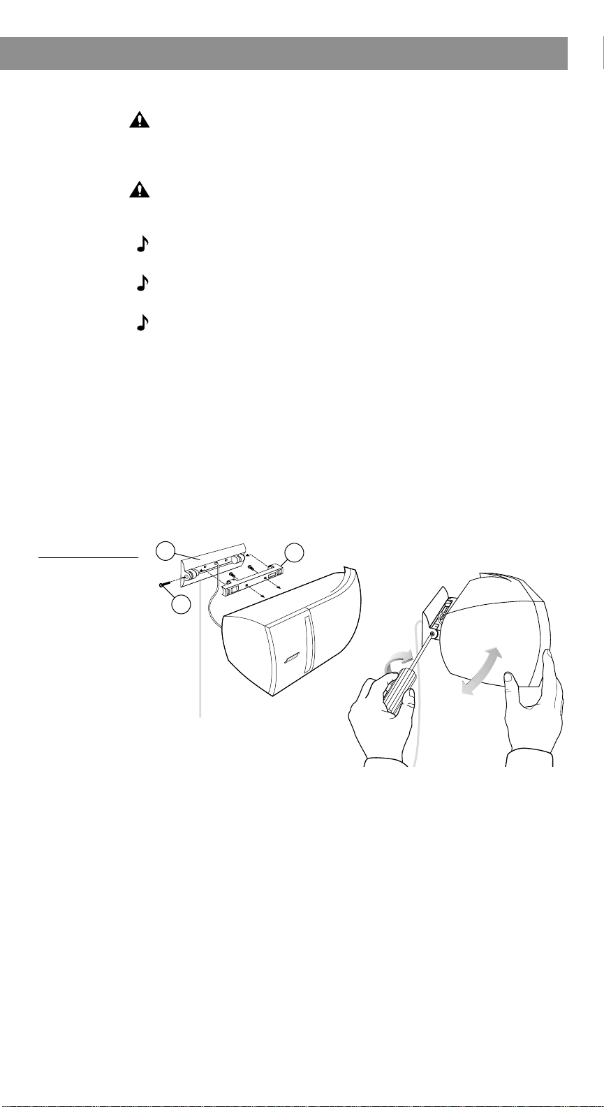
3. Mount bracket part A to the wall and mount bracket part B to
the rear of the speaker (Figure 8).
4. Secure the speaker with bracket part B to bracket part A
using screw C. To adjust the angle, loosen screw C slightly,
move the speaker up or down, and retighten screw C.
®
speaker performance, horizontal
Setting Up
Figure 8
Speaker-bracket
installation
AM257528_01_V.pdf October 26, 2001 11
Page 12

Adjusting Your Surround Sound Settings
6
7
8
9
10
11
12
13
141516
17
18
19
21
20
22
23
24
25
26
27
28
29
30
5
4
3
2
1
0
For realistic home theater sound
Each speaker produces only the sound directed to it by your surround sound receiver. During a surround sound program, the fr ont
and center speakers will emit sound almost constantly, while the
surround speakers may be silent at times.
How to set your Pro-Logic receiver
For use in video applications, be sure the SURROUND SOUND
center mode setting of your receiver is on NORMAL (Figure 9). You
may press in the button labeled Loudness (Bass Boost or Super
Bass on some receivers) to see if you prefer that video sound.
Figure 9
The receiver or
amplifier set to
NORMAL surround sound
mode
Use the test tone on your receiver to further verify connections
and to adjust the volume level of the speakers.
To use the test tone
1. Press test tone ON at the receiver remote.
2. Listen and confirm that each speaker reproduces sound as
the tone moves from speaker to speaker. One tone should
come from both SURROUND speakers at the same time.
3. Adjust the volume levels of the CENTER and SURROUND
speakers so all of the speakers sound equally loud in your
main listening area.
Instructions for this process vary , depending on the r eceiver brand
and model you are using. Follow your receiver owner’s guide
instructions for more details on using the test tone.
To balance the bass and treble
Upholstered furniture, wall-to-wall carpets, or heavy drapes can
muffle treble (high notes), making your speaker system sound
bass heavy. Bare floors and walls and hard surface furniture can
make your speaker system sound too shrill. After listening to your
speakers, you may want to adjust the balance of bass and treble.
You can use the bass and treble controls on your receiver.
12 October 26, 2001 AM257528_01_V.pdf
Page 13

Adjusting Your Surround Sound Settings
How to set your Dolby Digital receiver
Your VCS-10® or VCS-30® Series II speakers are compatible with
the output from Dolby Digital receivers. Take special care to set
the channel output on the Dolby Digital screen menu to SMALL for
both the center speaker and surround speakers.
Receiver channel output Proper setting
Center SMALL
Left and right surround speakers
(VCS-30 Series II surround speakers)
Follow the receiver owner’s guide instructions for using the
receiver test tone to verify your connections and to adjust the volume levels of the speakers.
If the sound is interrupted
The VCS-10 Center Speaker and VCS-30 Series II Center/Surround Speaker System feature an advanced automatic electronic
protection circuit to prevent speaker damage due to an overload.
When the center channel speaker detects an overload, the protection circuit intermittently shuts down and resets the speaker a
fraction of a second later , until the overload is clear ed. Intermittent
play will continue for the duration of the overload.
If you hear this interruption, turn down the volume to relieve the
overload. You will hear the speaker resume normal play when the
volume is set at a safe level.
Note: The overload problem described here should occur only if
the receiver is overdriven and sending a distorted signal, or when
the center speaker is driven by an amplifier rated well above the
100 watts per channel maximum listed in “Compatibility” on
page 15.
SMALL
AM257528_01_V.pdf October 26, 2001 13
Page 14

Reference
Troubleshooting
Problem What to do
No sound • Check the volume control.
• Make sure the receiver (or amplifier) is plugged in and
turned on.
• Check all connections (see page 10).
• Make sure the receiver is not on Mute.
• Make sure headphones are not connected to the receiver.
Center or surround
speaker does not
work
Center speaker
intermittently shuts
down
• Make sure your receiver has amplified center and surround
channels.
• Be sure your receiver is set properly (see page 12 and
page 13).
• Check the audio source material to be sure it is encoded
for surround sound.
• Check the speaker connections. (see page 10).
• If your surround sound receiver is Pro-Logic, be sure an
RCA stereo cable connects the receiver to a stereo sound
source (TV, VCR, laserdisc, or DSS player).
• If the receiver is connected directly to a stereo television,
make sure that all other program sources (VCR, laserdisc,
or DSS player) are connected to the TV using RCA stereo
cable as well.
• If your surround sound receiver is Dolby Digital, be sure
the sound source (DSS, laserdisc, or DVD player) is connected directly to your receiver as described in your
receiver owner’s guide.
• Reduce the volume until that speaker returns to normal
play. Automatic electronic protection circuitry may have
engaged to prevent an overload.
• Check the power rating of your receiver (see “Compatibility” on page 15).
• Make sure your receiver is set for NORMAL surround
sound mode.
Sound is distorted • Check the speaker cord for damage.
• Reduce the output level from your TV or other components
connected to the receiver.
Customer service
To arrange for service, contact your authorized Bose® dealer, or
contact Bose directly.
14 October 26, 2001 AM257528_01_V.pdf
Page 15

Cleaning speakers
CAUTION: If liquids get into the product, disconnect the speaker
from the receiver and allow it to air dry. Then reconnect the
speaker and play it. If you notice any problems with how the
speaker functions, disconnect it again and contact Bose
tomer service.
Clean the outside of your VCS-10
by wiping each speaker with a damp cloth. If necessary, use a
mild detergent, like dish soap, being careful not to allow any liquid
to spill through the cloth grille or the ventilation slots of the speakers. No other maintenance is required.
Warranty period
Bose® VCS-10 and VCS-30 Series II speakers are covered by a
limited 5-year transferable warranty. Details of the coverage are
provided on the warranty card that came with your speakers.
Please fill out the information section on that card, detach, and
mail it to Bose.
Technical information
Reference
®
cus-
®
or VCS-30® Series II speakers
Features
Ported speaker enclosures (all speakers)
Magnetic shielding in all speakers
Automatic electronic protection circuitry in all speakers
Syncom® computer quality control of center and surround
speakers
Driver complement per speaker
Center speaker: Four (4) 2.5" (6.3 cm) Twiddler™ drivers
Surround speaker: Two (2) 2.5" (6.3 cm) Twiddler™ drivers
Compatibility
Center speaker: Compatible with amplifiers or receivers with cen-
ter channel outputs rated 10-100 watts per
channel; rated 4-8 ohms
Surround speakers: Compatible with amplifiers or receivers with
surround channel outputs rated 10-100
watts per channel; rated 4-8 ohms
Enclosure
Black molded polymer with a tuned port
Size/Weight
Center speaker: 3.25"H x 21.5"W x 6"D; 5.9 lb
(8.2 cm x 54.6 cm x 15.2 cm; 2.7 kg)
Each surround speaker: 4.17"H x 10.93"W x 4.98"D; 3.3 lb
(14.6 cm x 28.0 cm x 16.5 cm; 1.49 kg)
VCS-10 speakers, packed in carton: 8 lb (3.6 kg)
VCS-30 Series II speaker system, packed in carton: 20 lb (9.1 kg)
AM257528_01_V.pdf October 26, 2001 15
Page 16

"
9
" (60 mm)
64
/
23
2
3
(13 mm)
(3 mm)
"
16
/
8
/
1
(6 mm)
"
4
/
1
" (30 mm)
16
/
1
(6 mm)
"
4
/
1
Drilling template
Optional speaker cord pilot hole
A
C
B
16 October 26, 2001 AM257528_01_V.pdf
Page 17

1
/8
"
(3 mm)
1
/4
"
(6 mm)
1
/8
"
(3 mm)
Wood wall
#10 x 1-1/2 in.
(#10 x 40 mm)
A
Masonry wall
#10
#10 x 1-1/2 in.
(#10 x 40 mm)
A
Wallboard wall
1
9
/2" —
(12-13 mm)
"
/16
A
#10-24 x 3 in.
(M5 x 75 mm)
1
/2" —
(12-13 mm)
1
"
9
"
/4
/16
(6 mm)
AM257528_01_V.pdf October 26, 2001 17
Page 18

©2001 Bose Corporation
The Mountain
Framingham, MA 01701-9168 USA
257528 AM Rev.01 JN10788
 Loading...