

Page 1
Lifestyle® V-Class
HOME THEATER SYSTEMS
Owner’s Guide
Guía de usario
Notice d’utilisation
™
Page 2

TAB TAB TAB 6 EnglishTAB English TAB 3TAB 2
The lightning flash with arrowhead symbol within an equilateral triangle alerts
the user to the presence of uninsulated, dangerous voltage within the system
enclosure that may be of sufficient magnitude to constitute a risk of electrical
shock.
The exclamation point within an equilateral triangle, as marked on the system,
is intended to alert the user to the presence of important operating and
maintenance instructions in this owner’s guide.
SAFETY INFORMATION
Please read this Owner’s Guide
Please take the time to follow the instructions in this guide carefully. It will help you set up and operate your system
properly and enjoy its advanced features. Please save this guide for future reference.
WARNING: To reduce the risk of fire or electrical shock,
do not expose the product to rain or moisture.
WARNING: The apparatus shall not be exposed to dripping or splashing, and objects filled with liquids, such as
vases, shall not be placed on the apparatus. As with any
electronic products, use care not to spill liquids into any
part of the system. Liquids can cause a failure and/or a
fire hazard.
ii
WARNING: No naked flame sources, such as lighted
candles, should be placed on the apparatus.
WARNING: To prevent electric shock, match the wide
blade of the line cord plug to the wide slot of the AC
(mains) receptacle. Insert fully.
Page 3
EnglishTAB 6ItalianoEnglish TAB TAB 3TAB 5 TAB 2TAB 4
SAFETY INFORMATION
CAUTION: Make no modifications to the system or
accessories. Unauthorized alterations may compromise
safety, regulatory compliance, and system performance.
Class B emissions
This Class B digital apparatus meets all requirements of
the Canadian Interference-Causing Equipment
Regulations (Canada only).
This product conforms to the EMC Directive 2004/108/EC
and to the Low Voltage Directive 2006/95/EC. The remote
control conforms to the RTTE Directive 99/5/EC. The
complete Declaration of Conformity can be found at
www.Bose.com/static/compliance/index.html.
Please dispose of used batteries properly, following
any local regulations. Do not incinerate.
Note: The product label is located on the bottom of the
product.
Note: Where the mains plug or appliance coupler is used
as the disconnect device, such disconnect device shall
remain readily operable.
Note: The product must be used indoors. It is neither
designed nor tested for use outdoors, in recreation vehicles,
or on boats.
Note: This product is intended to be used only with the
power supply provided.
Additional safety information
See the additional instructions on the Important Safety
Instructions sheet (North America only) enclosed in the
shipping carton.
For Your Records
Serial numbers are located on the bottom of the media center and the connection panel of the Acoustimass® module.
Serial numbers: Media center:________________________ Acoustimass module:___________________________
Dealer name:__________________________ Dealer phone:_____________________ Purchase date:____________
Bose recommends that you keep your sales slip and a copy of your product registration card together with this guide.
Be sure to fill out your product registration card and mail it to Bose.
Doing so is the only way to ensure that you will receive future software updates by mail.
iii
Page 4

TABLE OF CONTENTS
EnglishTAB 6ItalianoTAB TAB TAB 3TAB 5 TAB 2TAB 4
INSTALLATION ..........................................2
Welcome ..................................................................2
Your system features:........................................... 2
Setup assistance ......................................................2
Setup Guide.......................................................... 2
Setup and Demonstrations DVD........................... 3
This User Guide .................................................... 3
First Power-Up .........................................................4
What to do next .................................................... 4
Tailoring the sound to your room .............................6
Carton inventory .......................................................8
System parts.............................................. ... ... ..... 8
Cables and accessories........................................ 9
Placing the media center and display ....................10
Placing the cube speakers .....................................10
Placing the center speaker ................................. 11
Placing the front left and right speakers............. 12
Placing the rear speakers ................................... 12
Placing the Acoustimass
Making antenna connections .................................14
FM antenna connection...................................... 14
AM antenna connection...................................... 14
Cable radio as an option..................................... 14
Installing the TV on/off sensor ...............................15
Using a SCART adapter (Europe only) ...................17
Connecting the audio from your TV .......................18
Using the IR emitter ...............................................20
®
module .........................12
CONTROLS AND INDICATORS ................... 22
The display .............................................................22
The remote control .................................................22
OPERATION .......................................... 30
Watching TV ............................................... ... ... .... ..30
Setting up the Lifestyle remote to
control the TV...................................................... 30
Selecting the TV screen shape ........................... 31
Setting the audio delay compensation ............... 31
Changing the HDMI Image View......................... 31
Controlling a cable or satellite box .........................32
Programming the Bose remote to
turn the cable or satellite box on or off............... 32
Using the remote to change channels................ 33
Changing the HDMI Image View......................... 33
About the HDMI video resolution.......... ... ........... 33
iv
Page 5

TAB TAB TAB 6 TAB TAB English TAB 3TAB 2
TABLE OF CONTENTS
Controlling DVD playback ..................................... 34
Programming the Lifestyle
®
remote to
control the DVD player....................................... 34
Changing the HDMI Image View........................ 35
About the HDMI video resolution....................... 35
Setting up to view videotapes ............................... 36
Setting up the Bose remote to control the VCR 36
About the HDMI video resolution....................... 37
Setting up an auxiliary (AUX) source ..................... 38
Setting up the Bose
®
remote to control the
AUX device...... ................................................... 38
About the HDMI video resolution....................... 39
Controlling the (HDMI) Image View ....................... 40
Changing the HDMI video resolution .................... 43
Listening to the radio ............................................. 44
Presets......... ... ... .... ... ......................................... 44
Headphone listening ............................................. 44
Settings Options .................................................... 45
System maintenance ............................................. 50
Replacing the remote control batteries.............. 50
Changing remote control switch settings .......... 50
REFERENCE ..........................................50
Protecting and caring for your system............... 52
Cleaning the media center ................................. 53
Setting up a second room with sound ..................54
®
Bose
link-compatible products make it easy... 54
®
Bose
link remote switch settings...................... 55
Troubleshooting ...................... ................ ............... 56
Contacting Customer Service ...............................60
GLOSSARY ............................................61
v
Page 6

INSTALLATION
EnglishTAB 6ItalianoTAB TAB TAB 3TAB 5 TAB 2TAB 4
Welcome
Thank you for choosing a Bose® Lifestyle® V-Class™
home theater system. This elegant and easy-to-use
system delivers superior performance for both music and
video programming.
Your system features:
•HDMI connectivity
• The ability to up-convert video
• Proprietary ADAPTiQ
which optimizes system performance to your
listening room
• Capability of expanding your system to up to 14
other rooms
®
audio calibration system,
Setup assistance
The following information is provided to help you set up
your system:
Setup Guide
If you haven’t already done so, please refer to the fold-out
Setup Guide. It contains all the steps needed to get you
through basic system installation, including:
• System placement
• Speaker connections
• Display/media center interconnections
• TV/video connections
• Audio connections
• System power connections
2
Page 7

TAB TAB TAB 6 TAB TAB English TAB 3TAB 2
INSTALLATION
Setup and Demonstrations DVD
The Setup and Demonstrations DVD is a valuable
resource for setup information and content that
demonstrates the capability of your Lifestyle
Weencourage you to view the DVD immediately after you
set up your Lifestyle
®
system and connect your DVD
player using the Setup Guide. The setup DVD:
• Provides instructions for optimizing speaker
placement
• Explains the importance of running the ADAPTiQ
audio calibration system
• Demonstrates the capabilities of your Lifestyle
system
®
system.
®
®
This User Guide
This User Guide shows you how to complete your system
setup, and get the most out of your system. The following
information is provided in this user guide:
• ADAPTiQ audio calibration system
Shows how to initiate the ADAPTiQ audio calibration
system so that your Lifestyle
calibrated to produce the best sound possible in your
listening space.
• Speaker placement
Diagrams and explains how to place your speakers to
get the best possible sound.
• Antenna connections
Illustrates how to connect the AM and FM antennas.
• TV sensor setup
Shows how to enable the TV to turn on when a video
source (DVD, VCR, etc.) is selected.
• TV audio out connections
Explains how to connect audio from your TV so that
you can hear audio from camcorders, game
consoles, etc.
• Display and remote control buttons
Details the functions of buttons on the display and
remote control.
• Remote control setup
Shows how to set up the remote to control devices.
®
system can be
3
Page 8
INSTALLATION
EnglishTAB 6ItalianoTAB TAB TAB 3TAB 5 TAB 2TAB 4
First Power-Up
After you connect your Lifestyle® system to your TV and
DVD player using the Setup Guide, you are ready to apply
power .
®
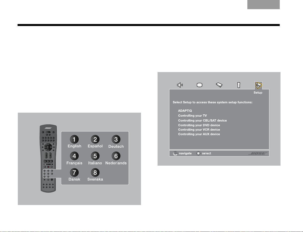
1. Turn on the TV and Lifestyle
The first time you apply power to your Lifestyle
tem, you are guided through a sequence of menus.
The first menu displayed on the TV (see Figure 1)
directs you to choose the system language.
Figure 1 Lifestyle® language menu.
system.
®
sys-
2. Select a language by pressing the corresponding
numeric key on the remote control.
The Setup menu appears as shown in Figure 2.
Figure 2 System menu Setup tab.
4
Page 9
TAB TAB TAB 6 TAB TAB English TAB 3TAB 2
INSTALLATION
What to do next
The first time the System menu Setup tab displays, you
can take one of the following actions:
• If you are confident that your speakers ar e correctly
wired and placed, and that you can understand and
navigate the Setup menu, continue using it. See
“Operation” beginning on page 30 for more information on using the Setup menu.
• If you would rather be guided through the setup
process by the Bose
DVD, do the following:
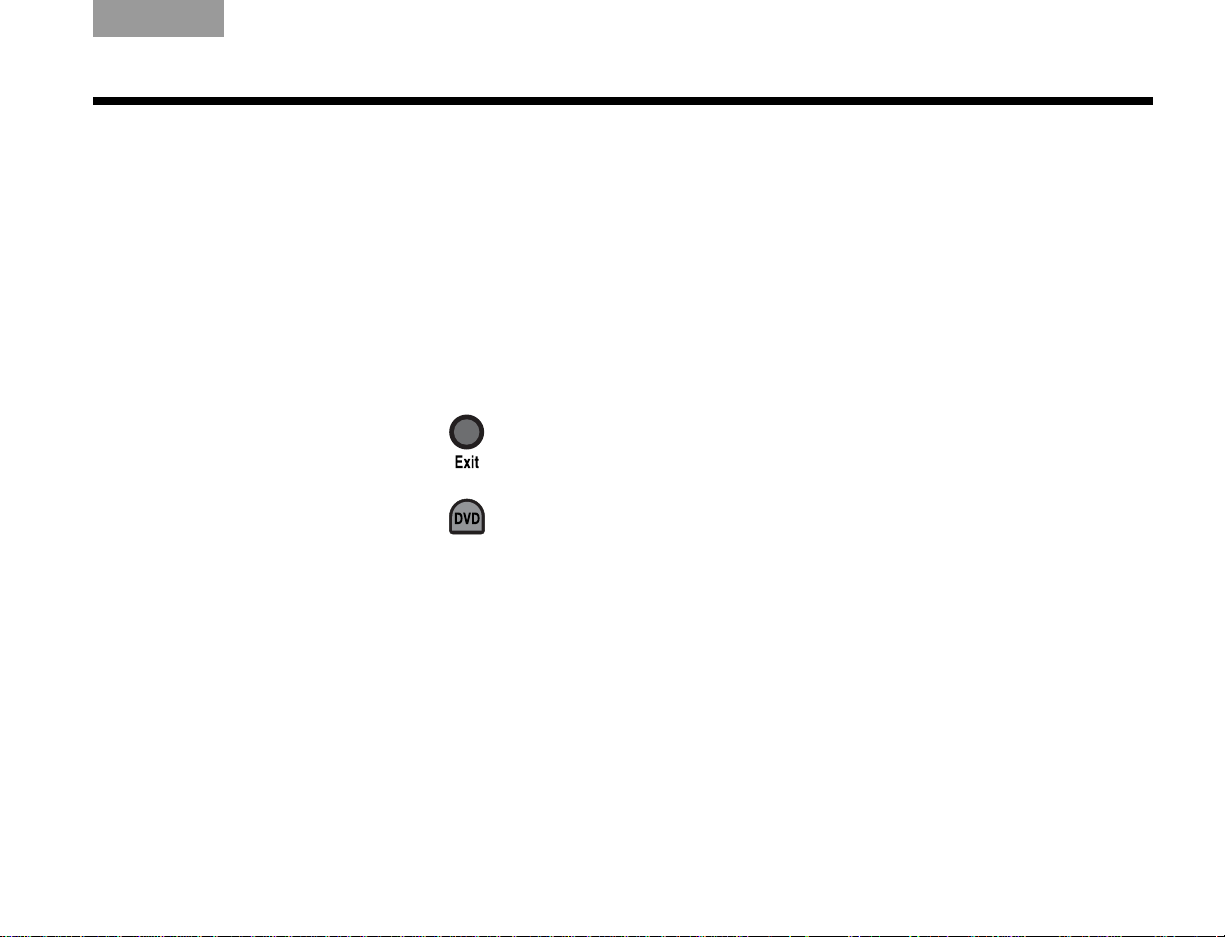
1.Exit the System menu by pressing on the
®
Lifestyle
remote.
2.Select the DVD player by pressing on the
Lifestyle
®
remote.
3.T urn your DVD player on and insert the Bose
Setup and Demonstrations DVD.
®
Setup and Demonstrations
®
The Setup and Demonstrations DVD should begin
playing. If not, press the PLAY button on the DVD
remote control. Follow the instructions on the DVD.
When you are finished with the Setup and Demon-
strations DVD, see “Operation” beginning on
page 30 for more information on using the Setup
menu.
5
Page 10
INSTALLATION
EnglishTAB 6ItalianoTAB TAB TAB 3TAB 5 TAB 2TAB 4
Tailoring the sound to your room
The ADAPTiQ® audio calibration system ensures that your
Lifestyle
audio calibration system process is the final step of a
basic Lifestyle
If you have already completed the ADAPTiQ audio
calibration system process using the Bose
Demonstrations DVD please go on to the next section,
“Carton inventory” on page 8.
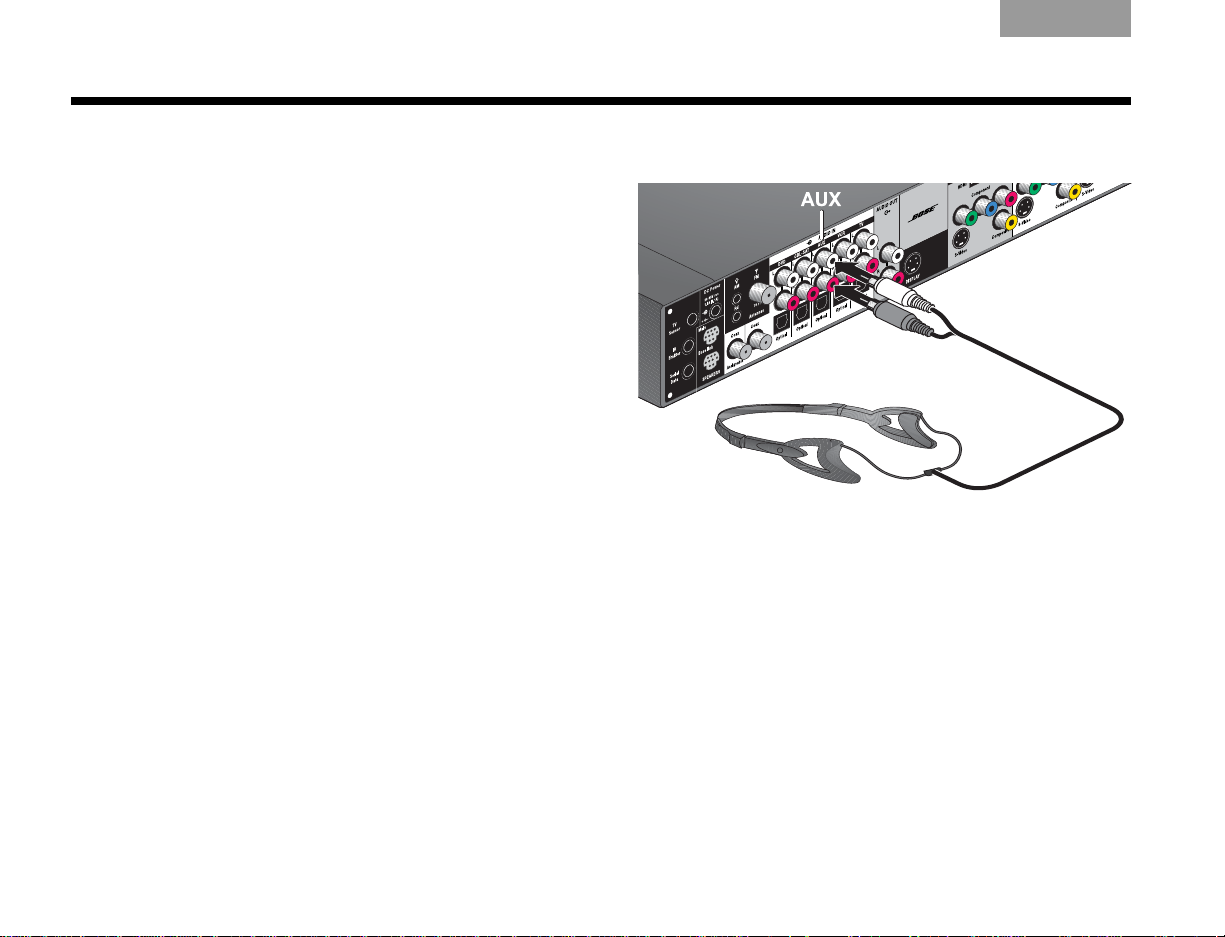
A special headset, pictured in Figure 3, can be found in
the Essentials kit. The headset, designed to be worn
above your ears, contains two miniature micr ophones that
take acoustic measurements during calibration.
You will achieve the best results when the listening room
is relatively quiet. Please notify other members of your
household that they will hear a series of audio tones.
On the connection panel of the media center (shown in
Figure 3), plug the ADAPTiQ headset into the AUX
AUDIO IN connectors.
®
system sounds great. Completing the ADAPTiQ
®
setup.
®
Setup and
Figure 3 ADAPTiQ headset connection.
6
Page 11

TAB TAB TAB 6 TAB TAB English TAB 3TAB 2
INSTALLATION
If you are applying power to your Lifestyle
®
system for the
first time, see “First Power-Up” on page 4.
To run the ADAPTiQ
®
audio calibration system process,
complete the following steps:
1. In the System menu Setup tab (see Figur e 4), move to
the ADAPTiQ item by pressing the down arrow .
Figure 4 System menu Setup tab
2. Press the right arrow to select Run.
3. To begin the ADAPTiQ audio calibration process,
press (Enter).
4. Follow the on-screen directions to complete the
process.
7
Page 12
INSTALLATION
EnglishTAB 6ItalianoTAB TAB TAB 3TAB 5 TAB 2TAB 4
Carton inventory
Now that you have unpacked your system, please save all
of the packing materials, which provide the safest means
for shipping or transporting.
Note: Now is a good time to locate the serial numbers for your
system, on the bottom of the media center and near the connection panel on the Acoustimass® module. For future reference, we suggest that you copy those numbers onto the For
Your Records form on page iii.
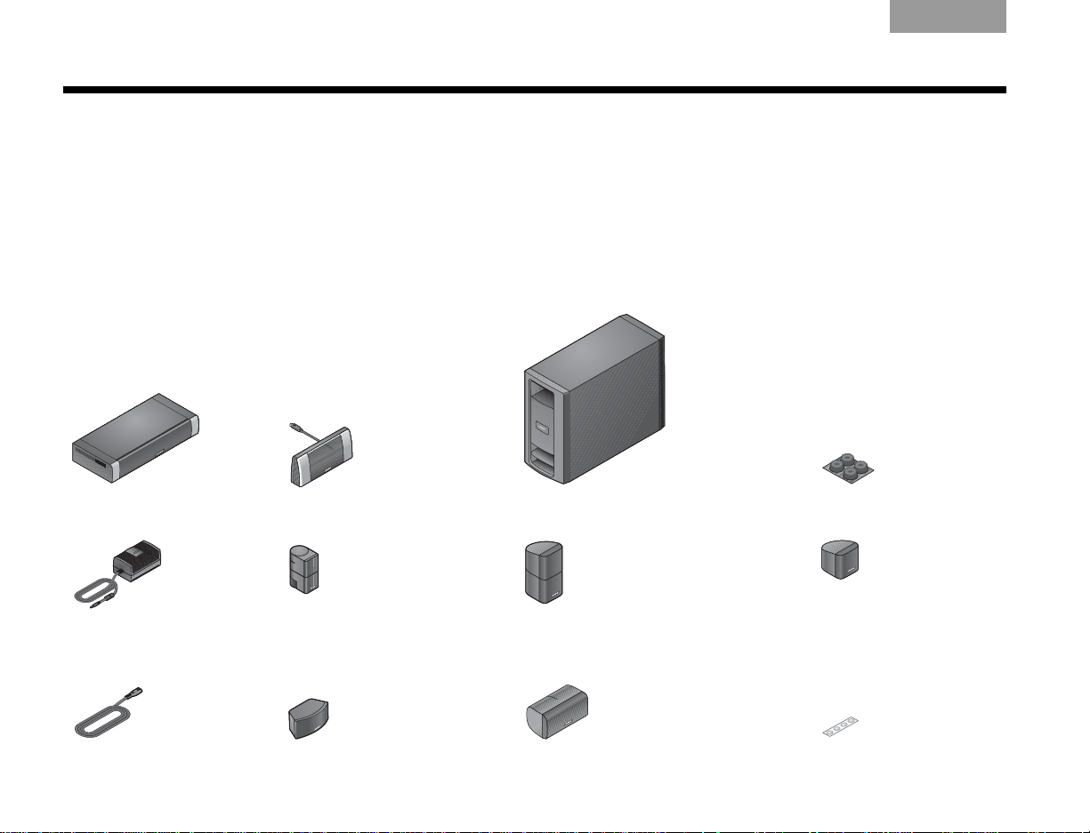
System parts
Verify that your system includes the following parts shown
in Figure 5.
Figure 5 System parts
❏ Media center ❏ Display ❏ Acoustimass® module ❏ Rubber feet for
❏ Power Supply ❏ Jewel Cube
(Lifestyle
®
®
speakesr (4)
V30)
❏ Direct/Reflecting
(Lifestyle
®
V20)
®
cube speakers (4)
Acoustimass® module
❏ Single Cube speaker (5)
(Lifestyle® V10)
❏ AC Power (2) ❏ Center channel speaker (1)
(Lifestyle
®
V30)
8
❏ Center channel speaker (1)
(Lifestyle® V20)
❏ Rubber feet for speakers
Page 13
TAB TAB TAB 6 TAB TAB English TAB 3TAB 2
INSTALLATION
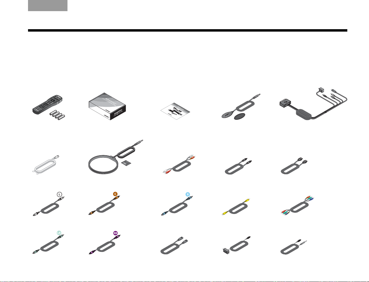
Cables and accessories
Verify that the items in Figure 6 ar e supplied. Cables
needed to get your system operational are included.
(Europe only), and TV sensor are also included. You may
need to acquire other cables or accessories to complete
your unique home theater setup as preferred.
Accessories such as antennas, SCART connector
Figure 6 Cables and accessories
❏ Remote control and
batteries
❏ FM dipole antenna ❏ AM loop antenna ❏ RCA analog audio ❏ Optical digital audio ❏ HDMI digital audio/video
❏ ADAPTiQ® audio calibration
system
❏ Setup and
Demonstrations DVD
❏ TV sensor ❏ SCART video connector
(Europe only)
❏ Left front speaker ❏ Center front speaker ❏ Right front speaker ❏ Composite video ❏ Component video
®
❏ Left rear speaker ❏ Right rear speaker ❏ Acoustimass
to media center
module
❏ IR emitter extender ❏ IR emitter
9
Page 14
INSTALLATION
Display module
EnglishTAB 6ItalianoTAB TAB TAB 3TAB 5 TAB 2TAB 4
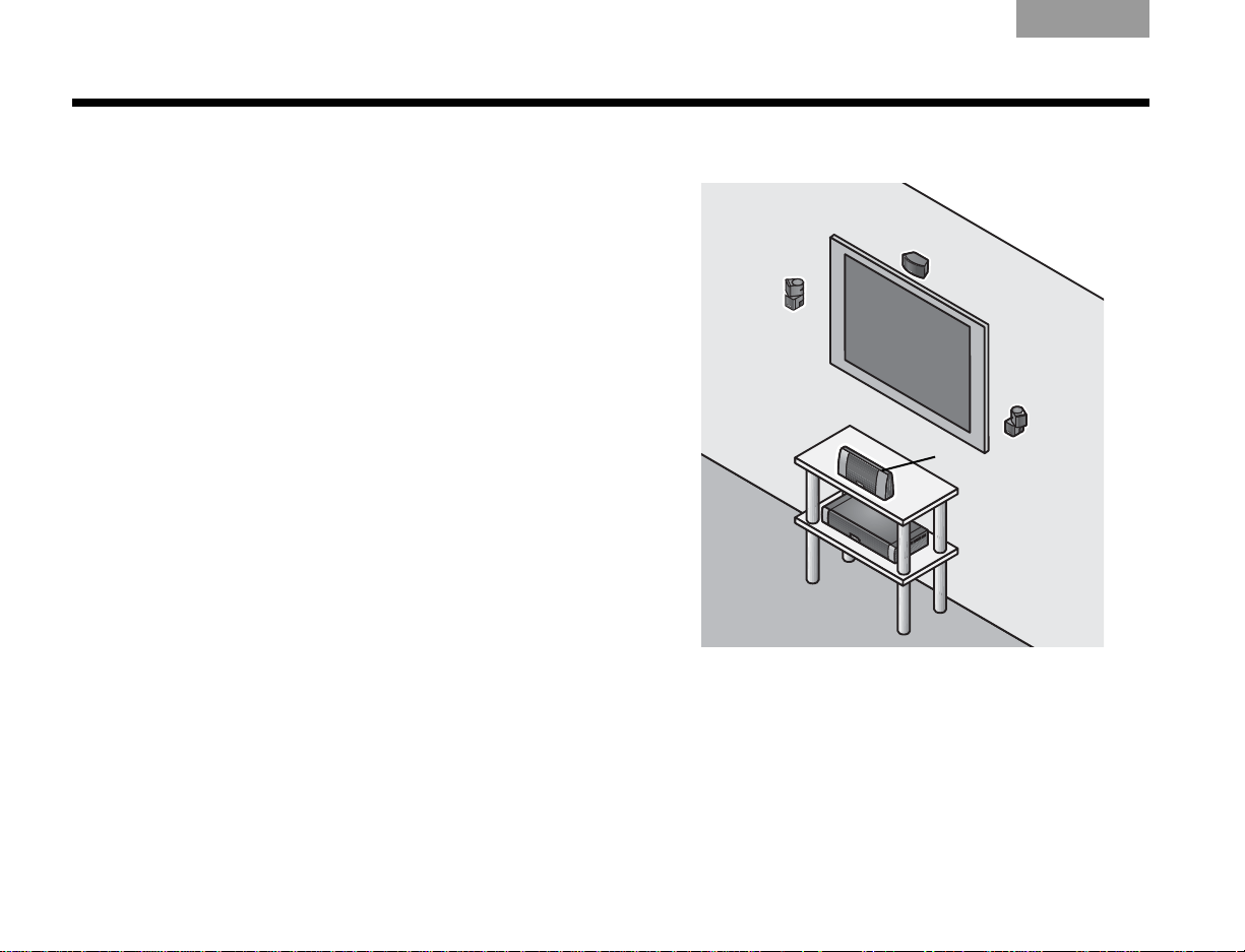
Placing the media center and display
The media center can be placed out of sight behind all of
your other A/V components. When placing the media
center , ensure that it is close enough to other sources (TV,
DVD, VCR, cable or satellite box) to allow for easy cable
connections. Check the length of the audio and video
cables you will use for these additional components.
CAUTION:
side of the media center. Allow at least two inches on each side.
Place the display module so it is facing out into the room,
toward the front of the surface on which it rests, as shown
in Figure 7. Allow about two inches of clearance on either
side of the display module. Make sure you can clearly see
the display module from your listening position.
Bose offers a variety of speaker mounting accessories,
including rubber feet, stands, and wall brackets. For more
information, or to purchase accessories, contact your
local Bose
Bose directly , r efer to the addr ess list pr ovided in the
carton.
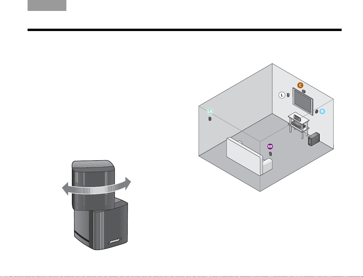
Rotate the top cube of each speaker array toward the wall
or another hard surface to create reflected sound.
Do not block the ventilation openings on either
®
dealer or visit www.Bose.com. To contact
Figure 7 T ypic al place ment of the Lifestyle® display module
10
Page 15
TAB TAB TAB 6 TAB TAB English TAB 3TAB 2
INSTALLATION
Placing the cube speakers
When you place your speakers approximately as shown in
Figure 8 on page 11, they provide the audio atmosphere
of a home theater . You can experiment with speaker
placement and orientation to produce the most pleasing
sound.
CAUTION:
Vibration can cause speakers to move, particularly on smooth
surfaces such as marble, glass, or highly polished wood. To
reduce the possibility of movement, Bose recommends that you
attach the included rubber speaker feet to the bottom of the
speakers.
Note: If, after running the ADAPTiQ
system, you move one or more speakers to a substantially different location, you should re-run the ADAPTiQ
audio calibration system.
Select a stable and level surface for all speakers.
®
audio calibration
®
Rotate the top cube toward a wall or
other hard surface.
Figure 8 Approximate speaker locations
11
Page 16

INSTALLATION
EnglishTAB 6ItalianoTAB TAB TAB 3TAB 5 TAB 2TAB 4
Placing the center speaker
• Place the center speaker directly above or below the
vertical center of the TV screen or as close to that as
possible (see Figur e 8).
• If you are placing the center speaker directly on the
top of your TV, first attach the supplied rubber feet to
the bottom surface of the speaker.
• Make sure the 20-foot (6.1-meter) speaker cable can
reach from the center speaker to the Acoustimass
®
module.
Placing the front left and right speakers
• Set or mount the front left and right speakers upright
and lined up with the horizontal center of the TV
screen.
• We recommend a maximum distance of 3 feet
(1 meter) from the edge of your TV screen for
best results.
• Make sure each 20-foot (6.1-meter) speaker
cable can reach from the speaker to the
Acoustimass module.
Placing the rear speakers
• Position the rear left and right speakers in the back
half of your room.
• Make sure each 50-foot (15.2-meter) speaker
cable can reach from the speaker to the
Acoustimass module.
• Place the speakers at ear height or higher if possible.
• Direct the sound away from the listening positions to
maximize the reflected sound.
12
Page 17
TAB TAB TAB 6 TAB TAB English TAB 3TAB 2
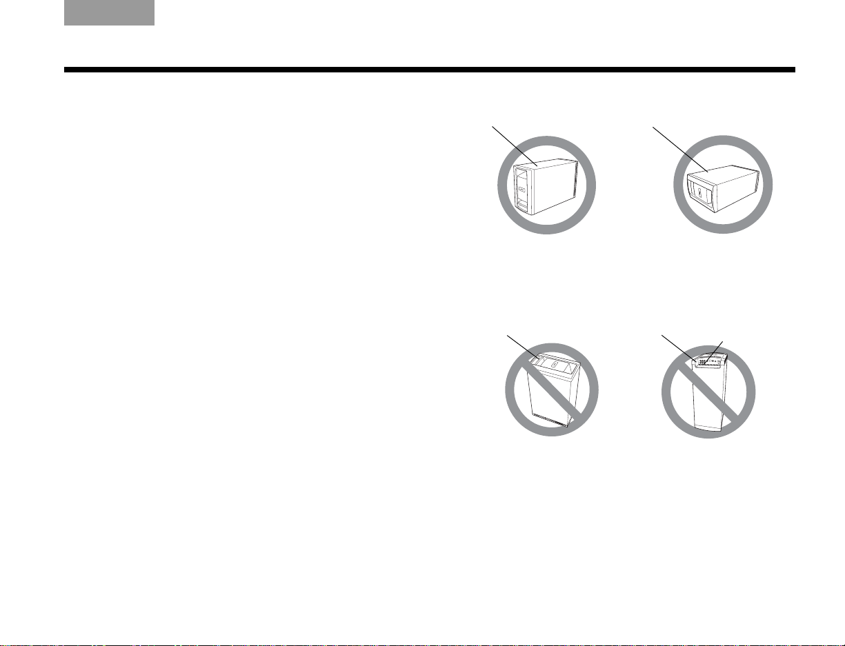
module on its bottom
surface,
ALTERNATE
Place the module on one
of its two broad
sides.
Top surface
Side surface
DO NOT
stand the module on its
slightly curved back end,
which can cause it to tip
DO NOT
stand the module on its front
grille end. The weight of
the module can damage
the grille.
Back end
Front end
Ventilation
openings
INSTALLATION
Placing the Acoustimass® module
Attach the four self-adhesive rubber feet to the surface
that touches the floor (either of its two sides, its top,
or bottom).
Place the Acoustimass® module:
• At the same end of the room as the front speakers.
• At least 18 inches (45 centimeters) from the TV to
avoid magnetic interference with the TV image.
• With the front end facing into the room.
• Within r each of the audio input cable, the five speaker
cables, and your AC power (mains) outlet.
• Under a table or behind a cabinet, but not where
furniture or drapes block any openings on the
module.
• On its two sides, its top, or bottom (Figur e 9).
Do NOT place the Acoustimass module:
• On its back end or front end (Figure 9).
• Where the ventilation slots for the built-in electronic
circuitry are blocked.
Figure 9 Proper and improper Acoustimass module positioning
• Wher e it will expose electr onic media, such as tapes,
to its magnetic field for long periods.
• Where the front end is facing a wall.
13
Page 18
INSTALLATION
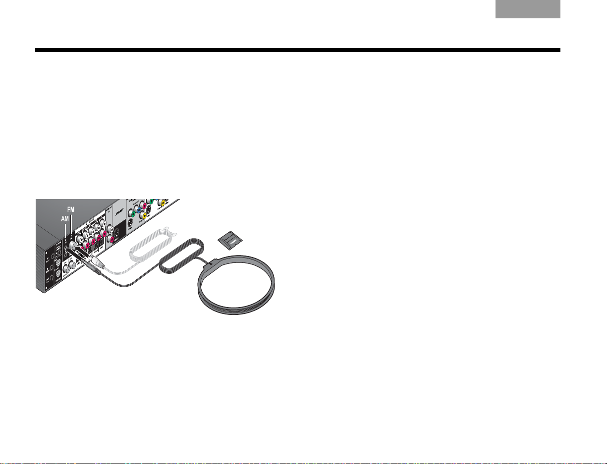
AM
FM AM base
EnglishTAB 6ItalianoTAB TAB TAB 3TAB 5 TAB 2TAB 4
Making antenna connections
The supplied AM and FM antennas connect to the rear
panel of the media center (Figure 10).
Note: The FM connector may be used with an
outdoor antenna. Before doing this, consult a qualified
installer. Follow all safety instructions supplied with
the antenna.
Figure 10 Connections for the AM and FM antennas
FM antenna connection
1. Plug the connector on the FM dipole antenna lead
into the FM antenna jack.
3. Keep the antenna as far as possi ble from the media
center, display, and Acoustimass
®
module.
AM antenna connection
1. Plug the connector on the AM loop antenna lead
into the AM antenna jack.
2. Stand the AM antenna on the base or mount the
antenna on a wall, following the instructions
enclosed with the AM antenna.
3. Keep the antenna as far as possible (at least 20
inches or 50 centimeters) from the media center
and display module, and at least 2 feet (60
centimeters) from the Acoustimass module.
Note: AM reception can be adversely affected by a
nearby television when it is on. Turn off the TV for best AM
reception.
Cable radio as an option
Some cable TV providers make FM radio signals available
through the cable service to your home. This cable
connects to the FM antenna jack on the back panel of the
media center.
For instructions on how to make this connection, contact
your cable TV provider.
2. Spread out the antenna arms and change their
orientation as needed to get th e best FM rec eption.
14
Page 19
TAB TAB TAB 6 TAB TAB English TAB 3TAB 2
Media center
TV sensor
INSTALLATION
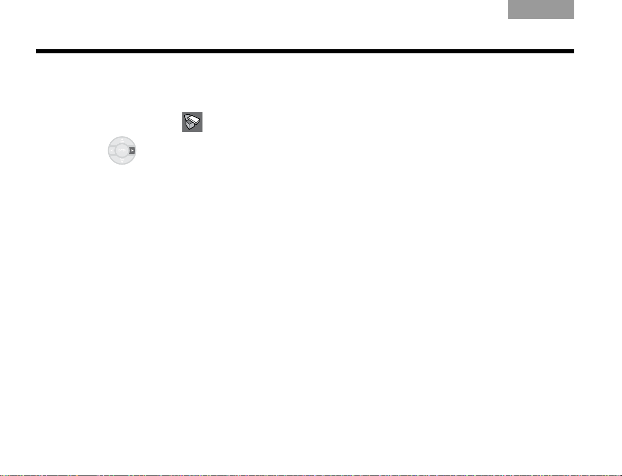
Installing the TV on/off sensor
The TV on/off sensor enables the system to automatically
turn on the TV when another video source (DVD, cable/
satellite box, etc.) is selected. If you choose not to use the
sensor, you must turn on your TV separately .
For a larger TV, you may want a second person to help as
you follow the steps below:
Note: Front projectors with a separate screen may not
work with the sensor.
Figure 11 TV on/off sensor positioned on the TV
1. Plug the sensor cord conn ector into the media
center TV Sensor connector.
If you are using a SCART adapter, plug the sensor
directly into the pass-thr ough connector provided
on the adapter (Figure 12 on page 17).
2. Temporarily position the TV on/off sensor on the
back of your TV (Figure 11).
Note: DO NOT attach the supplied mounting pad until
you have tested and activated the automatic feature as
explained below.
15
Page 20
INSTALLATION
EnglishTAB 6ItalianoTAB TAB TAB 3TAB 5 TAB 2TAB 4
3. Using the remote control that came with your TV,
turn on your TV.
4. Using the Lifestyle
®
remote control, press System.
5. To move right to the Setup menu, press the
right arrow then press ENTER.
6. Move down to TV Power
by pressing the down
arrow, then press ENTER.
7. Move up or down to select the proper TV Power
option to detect the TV sensor:
• Automatic (for TV models that do not use a
European-style SCART connector).
• Euro Connector (for TV models that use a
European-style SCART connector).
8. Press ENTER.
Below the highlighted TV Power
item is TV Power
Status. The value for this item changes from Not
Detected to TV On, when the sensor is properly
positioned.
Note: It may be helpful to get an assistant for the next
step and have one person view the screen, while the
other moves the sensor.
9. Hold the sensor against the rear of the TV and
slowly move it around until TV Power Status
changes from Not Detected to TV On.
10. When the TV Power Status indicates TV On,
press Exit to exit the System menu.
This completes sensor activation.
16
Page 21
TAB TAB TAB 6 TAB TAB English TAB 3TAB 2
Using a SCART adapter (Europe only)
The SCART adapter plugs into the media center using five connectors as show below.
Figure 12 SCART composite video connections
INSTALLATION
17
Page 22

INSTALLATION
EnglishTAB 6ItalianoTAB TAB TAB 3TAB 5 TAB 2TAB 4
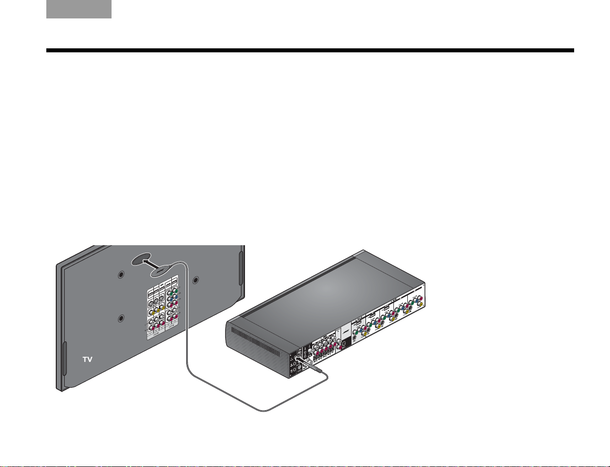
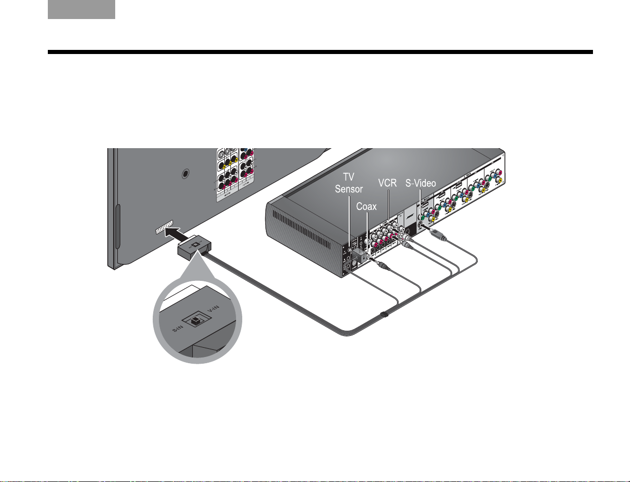
Connecting the audio from your TV
You may want to connect a source component, such as a
camcorder or game console, directly to your TV. To play
the audio from that source through your Lifestyle
you must connect the audio coming out of the TV to the
Lifestyle
®
system.
If your TV does not have an audio output, you can still
hear the sound of a connected component through the
speakers built into the TV. However, at any other time, it is
best to keep the volume of your TV turned all the way
down for a better surround sound experience.
®
system,
To connect your TV audio to the Lifestyle® system:
• For a basic analog audio connection, use the
supplied stereo audio cable (with two RCA
connectors at each end, one red and one white). It
connects to left (L) and right (R) audio outputs on the
rear panel of your TV a nd to the (L and R) TV Audio IN
jacks on the media center rear panel (see Figure 13).
• If your TV provides a digital audio out connector,
connect a digital audio cable. When making the
digital audio connection, use either a single coaxial
cable or an optical cable.
Do not disconnect the analog connection described
above. The analog connection ensures consistent
sound in the event of a weak digital signal.
• If your TV provides both fixed (FIX) and variable (VAR)
audio output jacks, use the fixed jacks for higher quality.
Be sure to select Fixed in your TV setup menu.
18
Page 23
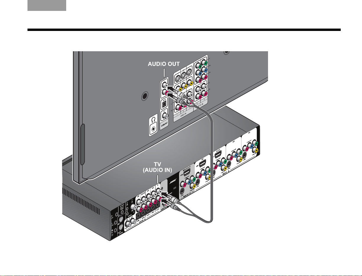
Figure 13 Audio connection between the TV and media center
TAB TAB TAB 6 TAB TAB English TAB 3TAB 2
INSTALLATION
19
Page 24

INSTALLATION
EnglishTAB 6ItalianoTAB TAB TAB 3TAB 5 TAB 2TAB 4
Using the IR emitter
IR emitters enable the system to control source devices
even if they are in a cabinet, on multiple shelves, or hidden
away . You should place an IR emitter on every device that
you want to control using the Lifestyle
To use an IR emitter with one device
1. Plug the IR emitter cord connector into the
Lifestyle
2. Place the emitter so that the flat side is against the
front panel of the source device.
3. Using the supplied adhesive pad, attach the
emitter to the device.
®
media center IR emitter connector.
®
remote.
Figure 14 IR emitters positioned on device front panel
20
Page 25
TAB TAB TAB 6 TAB TAB English TAB 3TAB 2
INSTALLATION
To use IR emitters with two or more devices
1. Plug the IR emitter extender connector into the
Lifestyle
2. Plug the IR emitter cord co nnector (or additional
extenders) into the IR emitter extend er.
3. Place each emitter so that the flat side is against
the front panel of each device.
4. Using the supplied adhesive pads, attach the
emitters to the devices.
Note: Y ou can use up to four IR emit ters with the system.
If you need additional IR emitter extenders, contact Bose
Customer Service. Refer to the address sheet included in
the carton.
®
media center.
Figure 15 IR emitters positioned on device front panel
®
21
Page 26
CONTROLS AND INDICATORS
Mute
Vol -
Vol +
EnglishTAB 6ItalianoTAB TAB TAB 3TAB 5 TAB 2TAB 4
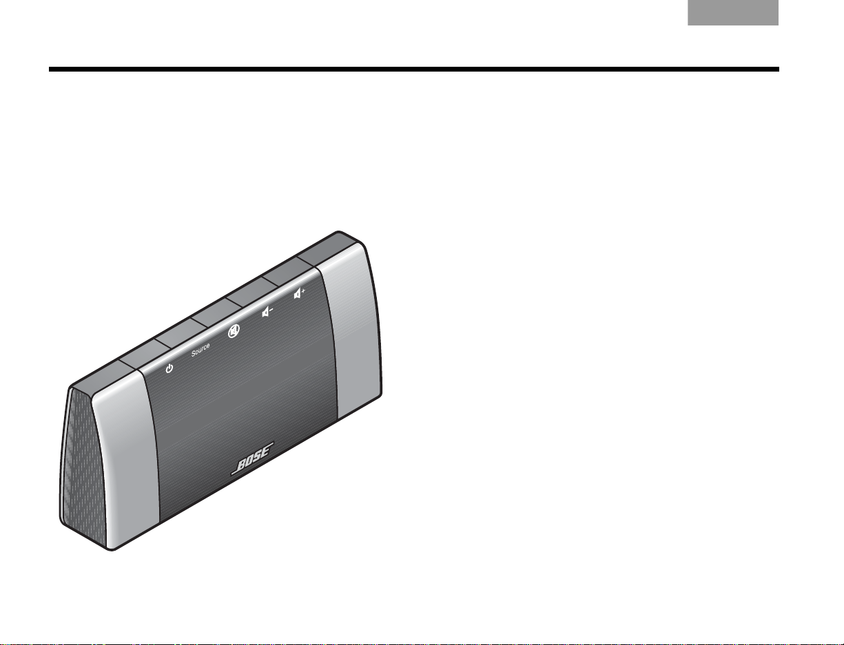
The display
The display shows system messages. This includes
program details, the current source that is playing, and
any selected option.
Figure 16 Lifestyle® system display
The buttons on the top of the display control the basic
Lifestyle
®
system functions.
Turns the power on or off. When Bose® link is
enabled, pressing and holding turns off all
zones. (See “Setting up a second room with
sound” on page 53.)
Steps through the available source selections.
Silences the speakers in the main room.
When Bose
holding silences the speakers in all rooms.
(See “Setting up a second room with sound”
on page 53.)
Decreases the audio volume from the
speakers.
Increases the audio volume from the
speakers.
®
link is enabled, pressing and
22
Page 27
TAB TAB TAB 6 TAB TAB English TAB 3TAB 2
CONTROLS AND INDICATORS
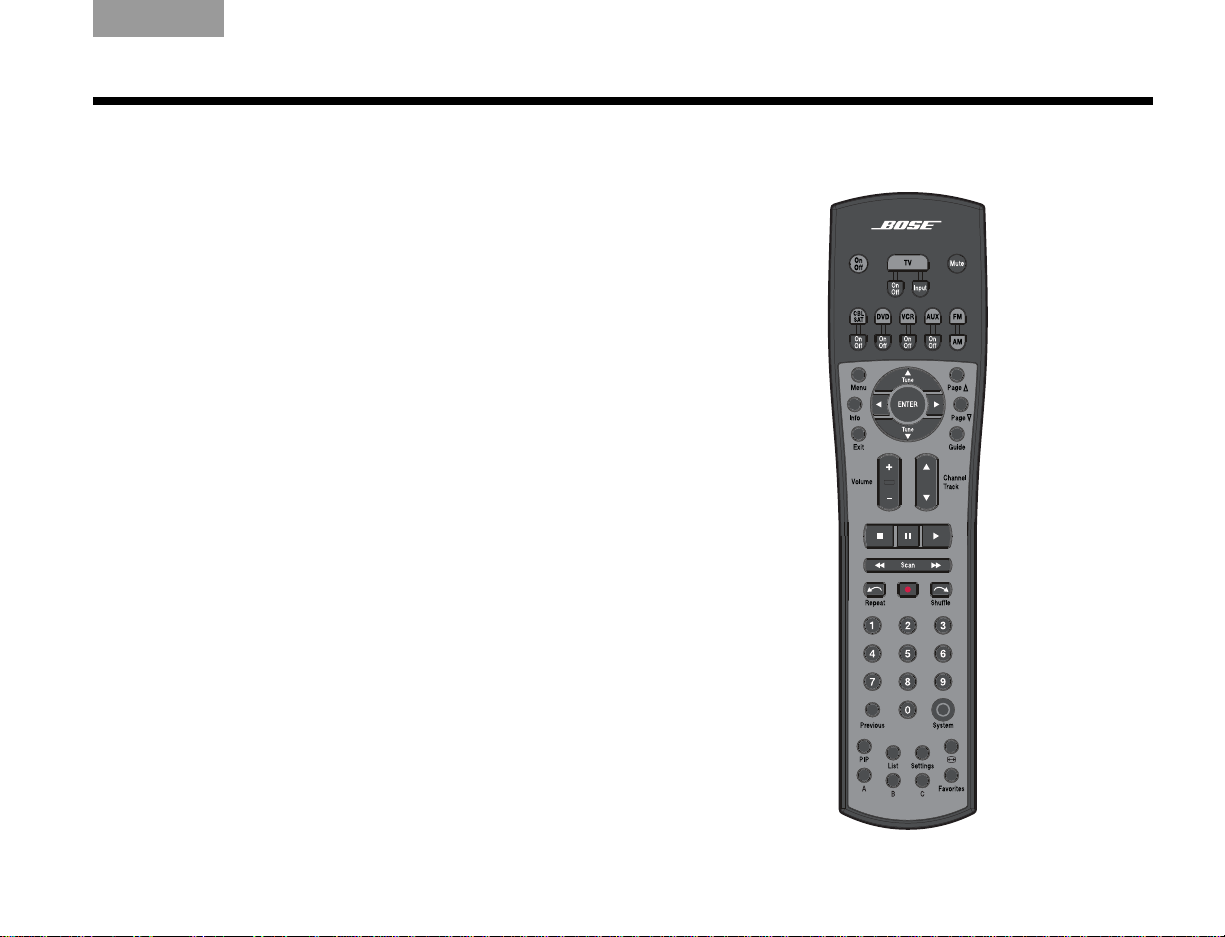
The remote control
The advanced radio frequency remote control works
from almost anywhere in your home. There is no need
to aim the remote at the display.
In addition to controlling your Lifestyle
remote can be programmed to control each source
device connected to your system.
The function of each remote contr ol bu tton is explained
on the following pages. Then, remote control programming is covered according to the activity as follows:
• “Watching TV” on page 30
• “Controlling a cable or satellite box” on page 32
• “Controlling DVD playback” on page 34
• “Setting up to view videotapes” on page 36
• “Setting up an auxiliary (AUX) source” on page 38
• “Listening to the radio” on page 44
®
system, the
Figure 17 Lifestyle® system remote control
23
Page 28
CONTROLS AND INDICATORS
EnglishTAB 6ItalianoTAB TAB TAB 3TAB 5 TAB 2TAB 4
Remote control button descriptions are arranged by
general function on the following pages. Some buttons
may not be physically grouped together. Refer to your
remote control while reading the following button
descriptions.
Before many of the buttons can function properly, your
Lifestyle
®
system remote must be set up to control the
associated source. See “Operation” beginning on
page 30.
Note: A source is any device, such as a DVD player,
that outputs video and/or audio and can connect to
your Lifestyle
®
system.
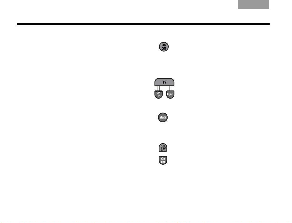
Power and source selection buttons
On/Off
and off, selecting the last used source at
turn-on. When Bose
– Turns the Lifestyle
®
link is enabled,
pressing and holding turns off all zones.
(See “Setting up a second room with
sound” on page 53.)
• TV – Turns your Lifestyle
was off. Selects the TV as the source.
• On/Off – Turns the TV on and off.
• Input – Selects dif ferent video
connectors on the TV.
Mute – Mutes or unmutes the volume.
When Bose
®
link is enabled, pressing and
holding silences the speakers in all rooms.
(See “Setting up a second room with
sound” on page 53.)
• CBL-SAT – Selects the source device
plugged into the CBL-SAT connectors.
Turns your Lifestyle
®
system on if it was
off.
• On/Off – Turns your cable or satellite
box on and off.
®
system on
®
system on if it
24
Page 29
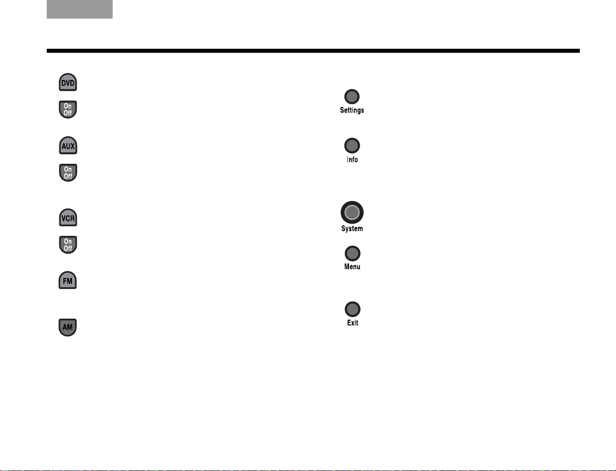
TAB TAB TAB 6 TAB TAB English TAB 3TAB 2
CONTROLS AND INDICATORS
• DVD – Selects the source device
plugged into the DVD connectors. Turns
your Lifestyle
®
system on if it was off.
• On/Off – Turns the DVD on and off.
• AUX – Selects the source device
plugged into the AUX connectors. Turns
®
your Lifestyle
system on if it was off.
• On/Off – Turns the AUX device on and
off.
• VCR – Selects the source device
plugged into the VCR connectors. Turns
your Lifestyle
®
system on if it was off.
• On/Off – Turns the VCR on and off.
FM – Selects the built-in FM radio tuner,
set to the station last selected. Turns your
Lifestyle
®
system on if it was off.
AM – Selects the built-in AM radio tuner set
to the station last selected. Turns your
Lifestyle
®
system on if it was off.
Menu and navigation buttons
Settings – Enters or exits the
Settings menu for the current source.
Info – Displays or exits the TV, cable,
satellite box, or VCR/DVR information
on the TV screen (when your TV,
cable or satellite box, or VCR/DVR
provides this feature).
System – Enters or exits the System
main menu.
Menu – Displays the options menu
for the current source (when your TV,
cable or satellite box, or VCR/DVR
provides this feature).
Exit
• Exits the Settings and System
menus.
• Exits on-screen menus for TV,
cable, satellite box, or VCR/DVR
(when your TV, cable or satellite
box, or VCR/DVR provides this
feature).
25
Page 30
CONTROLS AND INDICATORS
EnglishTAB 6ItalianoTAB TAB TAB 3TAB 5 TAB 2TAB 4
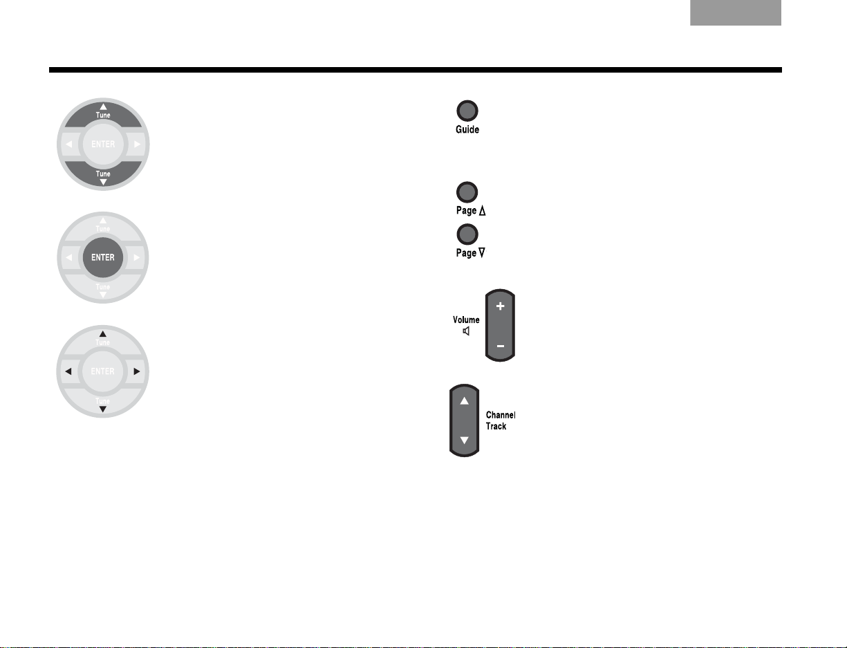
Tune Up/Down
• Tune the FM/AM radio up or
down to the next frequency.
• Select the next or previous
item in a menu list.
Enter – Confirm the selection
of a menu item.
Arrow Keys – Move up, down,
left, or right in a menu or
screen.
Guide – Displays an electronic
program guide (when your TV, cable,
satellite box or VCR/DVR provides
this feature).
Page Up/Down – Commands the
TV, Cable, or Satellite box to move up
or down a page in an on-screen
guide.
Volume – Raises or lowers the
volume.
• Pressing + raises the volume and
unmutes the system (if muted).
• Pressing
Channel/Track – Skips backward
or forward to the next TV, cable, or
satellite channel, CD track, or DVD
chapter.
–
lowers the volume.
26
Page 31

TAB TAB TAB 6 TAB TAB English TAB 3TAB 2
CONTROLS AND INDICATORS
Play mode and numeric buttons
Stop
• Stops music (except FM/AM) or video
play.
• For DVDs and VCDs only, th e system
inserts a bookmark where the disc
stopped (if your player supports this
feature), so you can resume play from
that point. Pressing again clears the
bookmark.
Pause – Pauses music (except FM/AM)
or video play.
Play – Starts music (except FM/AM) or
video play.
Scan
• Moves backward or forward in
video. Displays a control bar to
adjust the speed of this
movement.
• Moves to the previous or next
CD track or strong radio station.
When pressed and held, scans
backward or forward through the
current CD or MP3 disc.
Repeat
• Repeats the current music selection
from a CD. Pressing again cancels
repeat.
• Moves ahead a few seconds on your
DVR.
27
Page 32

CONTROLS AND INDICATORS
EnglishTAB 6ItalianoTAB TAB TAB 3TAB 5 TAB 2TAB 4
Record
• Activates recording on a recording
device.
Shuffle
• Randomly plays music from a CD.
Pressing again cancels repeat.
• Moves back a few seconds on your
DVR.
Numeric Keys – Select the radio
station preset, DVD chapter, CD
track, or TV channel that
corresponds to the numbers
pressed.
Previous – Skips to the channel last
selected on TV, cable, satellite box, VCR,
or DVR (if applicable).
Picture settings buttons
Picture-in-picture – Activates the picture-
in-picture feature of your TV (if your TV
includes this feature).
Image View– Allows you to specify how you
want certain display formats from your
Lifestyle
®
system to appear on your HDTV
screen.
28
Page 33

TAB TAB TAB 6 TAB TAB English TAB 3TAB 2
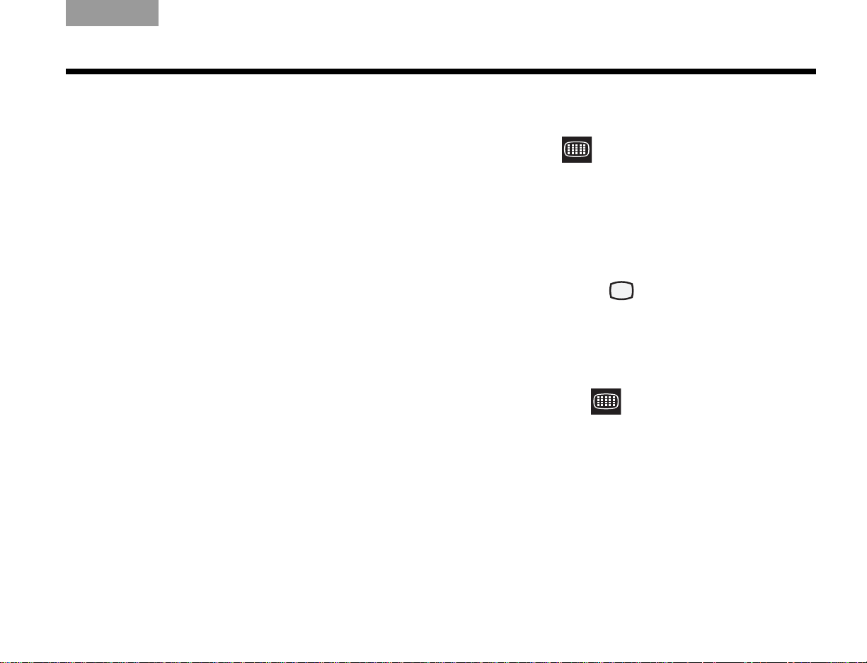
Special function buttons Teletext mode buttons (Europe only)
List – Activates the A, B, C, and Favorites
buttons at the bottom of the remote when a
DVR is the source.
Makes a selection from List A.
Teletext – Enters or exits the Teletext mode
when the TV is selected as the source. Works
in conjunction with the four colored buttons.
Red – In Teletext mode, selects the
content labeled red.
SETUP
Makes a selection from List B.
Makes a selection from List C.
Displays a list of favorite channels,
if your TV supports this feature.
Green – In Teletext mode, selects
the screen content labeled green.
Yellow – In Teletext mode, selects
the screen content labeled yellow.
Blue – In Teletext mode, selects the
screen content labeled blue.
29
Page 34

OPERATION
EnglishTAB 6ItalianoTAB TAB TAB 3TAB 5 TAB 2TAB 4
Watching TV
Your Lifestyle® system works with many different types
of TVs, from standard definition to Digital HighDefinition TV (HDTV). This section shows you how to
set up your Lifestyle
with your particular brand of TV, then configure the
sensor so your TV automatically turns on when you
press the On/Off button on the remote.
Setting up the Lifestyle® remote to control
the TV
Before you can control the TV, you must first select the
correct TV code by following the steps below.
1. Turn on the TV.
2. On the Lifestyle
remote control” on page 23 for information on
operating the remote.)
3. To display the Lifestyle
press System.
The message “SYSTEM: SEE TV” should appear
on the Lifestyle
Use the remote supplied with the TV to select the
video input that allows you to see t he Lifestyle
system menu.
®
system remote control to work
®
remote, press TV. (See “The
®
system menu on the TV,
®
system display module.
®
4. T o select the Setup tab, move right and select ,
then press ENTER.
5. Move down to TV Brand and press ENTER.
6. Select the brand of your TV fr om the list and press
ENTER.
7. Move down to TV Code and press ENTER.
8. Select the first TV code in the list.
9. Press the (TV) On/Off button (located under the TV
button).
• If the TV turns off, you have chosen the
correct code.
• If the TV does not tur n off, select the next co de
and press (TV) On/Off again.
Continue selecting codes until you find one
that works.
10. When you have a working code, enter it below , then
press ENTER.
TV Code: ____________________
11. To exit the system menu, press Exit.
30
Page 35

TAB TAB TAB 6 TAB TAB English TAB 3TAB 2
Normal
Widescreen
OPERATION
Selecting the TV screen shape
The shape of your TV screen is either Normal or
Widescreen (Figure 1). The Lifestyle
set to display an image on a widescreen-shaped TV. If
your TV is the normal shape, you should adjust the
Lifestyle
Figure 1 TV screen shapes
®
system setting from widescreen to normal.
1. Display the Lifestyle® system menu on the TV by
pressing System.
2. T o select the Setup tab, move right and select ,
then press ENTER.
3. Move down to Widescreen TV and press ENTER.
4. To indicate that you have a normal TV, select No
and press ENTER.
5. To exit the System menu, press Exit.
®
system is initially
Setting the audio delay compensation
You may notice that the au dio is delayed relative to the
video. For example, a person’s lips move but there is a
noticeable delay until you hear the voice. You can use
the Audio Delay setting to correct th is condition.
To change the audio delay:
1. Use the Lifestyle
®
remote to display the Settings
menu on the display module or TV by pressing
Settings.
2. Move down and select , then press ENTER.
3. Select a value by moving up or down the list, then
press ENTER.
The initial setting is 2 (to compensate for the
Lifestyle
®
system internal delay). Each value (1-8)
adds 30 milliseconds of delay.
4. To exit the Settings menu, press Exit.
Note: Under most listening conditions, you should keep
the volume on your TV set turned all the way down.
Changing the HDMI Image View
You can specify how certain display formats appear on
your HDTV screen. You control these formats (that are
output from your Lifestyle
Image View button on the remote. See “Controlling the
(HDMI) Image View” on page 40 and “Settings Options”
on page 45 for information and illustrations on changing
the HDMI Image View.
®
system) by pressing the
31
Page 36

OPERATION
EnglishTAB 6ItalianoTAB TAB TAB 3TAB 5 TAB 2TAB 4
Controlling a cable or satellite box
Once your cable or satellite box is connected to your
Lifestyle
single point of control for your subscription service.
Programming the Bose® remote to control
the cable or satellite box
Setting up the remote to control the cable or satellite
box involves selecting the correct cable or satellite box
code.
1. Turn on the TV.
2. Turn on the cable or satellite box.
3. To display the Lifestyle
4. T o select the Setup tab, move right and select ,
5. Move down to CBL
6. Select the correct device type from the list and
®
system, you can set up the remote as the
On the TV, select the video input that is connected
to the Lifestyle
®
system.
®
system menu on the TV,
press System. (See “The remote control” on
page 23 for informat ion on operating the remote.)
then press ENTER.
•SAT Device and press
ENTER.
press ENTER.
If you are unsure of the device type, see the
owner’s manual for that device.
7. Move down to CBL
•SAT Brand and press ENTER.
8. Select the brand of your device fr om the list and
press ENTER.
9. Move down to CBL
•SAT Code and press ENTER.
10. Select the first code in the list.
11. On the Lifestyle
®
remote, press the (CBL-SAT)
On/Off button, located under the CBL-SA T button.
• If the device turns off, you have chosen the
correct code.
• If the device does not turn off, select the next
code and press (CBL-SAT) On/Off again.
Continue selecting codes until you find one
that works.
12. When you have a working code, enter it below , then
press ENTER.
CBL-SAT Code: ____________________
13. To exit the system menu, press Exit.
32
Page 37

TAB TAB TAB 6 TAB TAB English TAB 3TAB 2
OPERATION
Using the remote to change channels
If you want the remote to change the channels on your
cable or satellite box when you are watching TV:
®
1. To display the Lifestyle
system menu on the TV,
press System.
2. Move down to TV Control and press ENTER.
3. Select CBL
•SAT and press ENTER.
Setting TV Control to CBL-SAT configures the
remote to control both the TV and cable or satellite
box when the source is TV.
4. To exit the system menu, press Exit.
You now can use your Lifestyle
®
remote to control your
cable or satellite box.
Changing the HDMI Image View
You can specify how certain display formats appear on
your HDTV screen. You control these formats (that are
output from your Lifestyle
Image View button on the remote. See “Cont rolling the
(HDMI) Image View” on page 40 and “Settings Options”
on page 45 for information and illustrations on changing
the HDMI Image View.
®
system) by pressing the
About the HDMI video resolution
When your Lifestyle® system is connected to an HDTV
using the HDMI connector, the video is transmitted at
the prefered resolution of the television. Occasionally,
you may want to specify a lower resolution, even
though your HDTV can display a higher resolution. For
example, a certain source signal may be unpleasant to
your eye when converted by the Lifestyle
much higher resolution. In that case, you can change to
a lower resolution. See “Changing the HDMI video
resolution” on page 43 for information on changing the
HDMI video resolution.
®
system to a
33
Page 38

OPERATION
EnglishTAB 6ItalianoTAB TAB TAB 3TAB 5 TAB 2TAB 4
Controlling DVD playback
Once your DVD player is connected to the Lifestyle®
system, you can set up the Lifestyle
control the DVD player.
Programming the Lifestyle® remote to control the DVD player
Setting up the remote to control the DVD player
involves selecting the correct DVD code, then setting
the DVD to turn on automatically when your Lifestyle
system is turned on.
1. Turn on the TV.
On the TV, select the video input that is connected
to the Lifestyle
2. Turn the DVD player on.
3. On the Lifestyle
remote control” on page 23 for information on
operating the remote.)
4. To display the Lifestyle
press System.
5. To display the Setup men u, select , then pr ess
ENTER.
6. Move down to DVD Device and press ENTER.
7. Move up or down to select the type of device from
the list and press ENTER.
8. Move down to DVD Brand and press ENTER.
®
system.
®
remote, press DVD. (See “The
®
system menu on the TV,
®
remote control to
®
9. Select the brand of your device and press ENTER.
10. Move down to DVD Code and press ENTER.
11. Select the first device code in the list.
12. On the Lifestyle
®
remote, press the (DVD)
On/Off button, located under the DVD button.
• If the DVD turns off, you have chosen the corr ect
code.
• If the DVD does not turn off, select the next
code and press DVD On/Off again.
Continue selecting codes until you find one
that works.
13. When you have a working code, enter it below , then
press ENTER.
DVD Code: ____________________
14. To exit the system menu, press Exit.
34
Page 39

TAB TAB TAB 6 TAB TAB English TAB 3TAB 2
OPERATION
Changing the HDMI Image View
You can specify how certain display formats appear on
your HDTV screen. You control these formats (that are
output from your Lifestyle
Image View button on the remote. See “Cont rolling the
(HDMI) Image View” on page 40 and “Settings Options”
on page 45 for information and illustrations on changing
the HDMI Image View.
®
system) by pressing the
About the HDMI video resolution
When your Lifestyle® system is connected to an HDTV
using the HDMI connector, the video is transmitted at
the prefered resolution of the television. Occasionally,
you may want to specify a lower resolution, even
though your HDTV can display a higher resolution. For
example, a certain source signal may be unpleasant to
your eye when converted by the Lifestyle
much higher resolution. In that case, you can change to
a lower resolution. See “Changing the HDMI video
resolution” on page 43 for information on changing the
HDMI video resolution.
®
system to a
35
Page 40

OPERATION
EnglishTAB 6ItalianoTAB TAB TAB 3TAB 5 TAB 2TAB 4
Setting up to view videotapes
Once your VCR is connected to your Lifestyle® system,
you can set up the remote to control the VCR and start
watching videotapes.
Programming the Bose® remote to control
the VCR
Setting up the remote to control the VCR involves
selecting the correct VCR code, then setting the VCR to
turn on automatically when your Lifestyle
turned on.
1. Turn on the TV.
On the TV, select the video input that is connected
to the Lifestyle
®
system.
2. Turn on the VCR.
3. On the Lifestyle
®
remote, press VCR. (See “The
remote control” on page 23 for information on
operating the remote.)
4. Press System to make the system menu appear
on the TV.
5. To display the Setup menu, select , then
press ENTER.
®
system is
6. Move down to VCR Device and press ENTER.
7. Select the type of device from the list and
press ENTER.
8. Move down to VCR Brand and press ENTER.
9. Select the brand of your device and press ENTER.
10. Move down to VCR Code and press ENTER.
11. Select the first device code in the list.
12. Press the (VCR) On/Off button (located under the
VCR button).
• If the VCR turns off, you have chosen t he correct
code.
• If the VCR does not turn off, select the next
device code and press VCR On/Off again.
Continue selecting codes until you find one
that works.
13. When you have a working code, enter it below , then
press ENTER.
VCR Code: ____________________
14. To exit the system menu, press Exit.
You can now use the Lifestyle
®
remote to control your
VCR.
36
Page 41

TAB TAB TAB 6 TAB TAB English TAB 3TAB 2
OPERATION
Changing the HDMI Image View
You can specify how certain display formats appear on
your HDTV screen. You control these formats (that are
output from your Lifestyle
Image View button on the remote. See “Cont rolling the
(HDMI) Image View” on page 40 and “Settings Options”
on page 45 for information and illustrations on changing
the HDMI Image View.
®
system) by pressing the
About the HDMI video resolution
When your Lifestyle® system is connected to an HDTV
using the HDMI connector, the video is transmitted at
the prefered resolution of the television. Occasionally,
you may want to specify a lower resolution, even
though your HDTV can display a higher resolution. For
example, a certain source signal may be unpleasant to
your eye when converted by the Lifestyle
much higher resolution. In that case, you can change to
a lower resolution. See “Changing the HDMI video
resolution” on page 43 for information on changing the
HDMI video resolution.
®
system to a
37
Page 42

OPERATION
EnglishTAB 6ItalianoTAB TAB TAB 3TAB 5 TAB 2TAB 4
Setting up an auxiliary (AUX) source
Once your AUX source device is connected to the
Lifestyle
that source. Then, when you are watching video from
that source, the Lifestyle
of the functions of that source.
Programming the Bose® remote to control
the AUX device
Setting up the remote to control the AUX device
involves selecting the correct AUX device code, then
setting the AUX device to turn on automatically when
the Lifestyle
1. Turn on the TV.
2. Turn on the AUX device.
3. On the Lifestyle
4. Make the system menu appear on the TV by
5. Move across the menu tabs to Setup by pressing
6. Move down to AUX Device and press ENTER.
®
system, you can set up the remote to control
®
remote should control most
®
system is turned on.
On the TV, select the video input that is connected
to the Lifestyle
®
system.
®
remote, press AUX.
pressing System.
the right arrow.
7. Select the type of device from the list and press
ENTER.
8. Move down to AUX Brand and press ENTER.
9. Select the brand of your device and press ENTER.
10. Move down to AUX Code and press ENTER.
11. Select the first device code in the list.
12. Press the (AUX) On/Off button (located under the
AUX button).
• If the AUX device turns off, you have chosen the
correct code.
• If the device does not turn off, select the next
code and press (AUX) On/Off again.
Continue selecting codes until you find one
that works.
13. When you have a working code, enter it below , then
press ENTER.
AUX Code: ____________________
14. To exit the system menu, press Exit.
You can now use the Lifestyle
®
remote to control your
auxiliary device.
38
Page 43

TAB TAB TAB 6 TAB TAB English TAB 3TAB 2
OPERATION
Changing the HDMI Image View
You can specify how certain display formats appear on
your HDTV screen. You control these formats (that are
output from your Lifestyle
Image View button on the remote. See “Cont rolling the
(HDMI) Image View” on page 40 and “Settings Options”
on page 45 for information and illustrations on changing
the HDMI Image View.
®
system) by pressing the
About the HDMI video resolution
When your Lifestyle® system is connected to an HDTV
using the HDMI connector, the video is transmitted at
the prefered resolution of the television. Occasionally,
you may want to specify a lower resolution, even
though your HDTV can display a higher resolution. For
example, a certain source signal may be unpleasant to
your eye when converted by the Lifestyle
much higher resolution. In that case, you can change to
a lower resolution. See “Changing the HDMI video
resolution” on page 43 for information on changing the
HDMI video resolution.
®
system to a
39
Page 44

OPERATION
4:3
16:9
EnglishTAB 6ItalianoTAB TAB TAB 3TAB 5 TAB 2TAB 4
Controlling the (HDMI) Image View
Y ou can specify how you want certain display formats that
are output from your Lifestyle
HDTV screen by pressing the Image View button on the
remote. This button has an effect only when your
Lifestyle
®
system is connected to a widescreen (16:9
aspect ratio) HDTV through the HDMI OUT connector.
To change the display format that is output from your
Lifestyle
®
system, press (Image View) on the
remote.
The Image View (aspect ratio) control that is built into
the HDTV must be set so that the Lifestyle
Image View settings have the intended effect. Refer to
the manual that came with your HDTV to find out how
to set its Image View.
®
system to appear on your
®
system
Pressing the Image V iew butt on causes dif fer ent r esults
depending on the aspect ratio of the signal input to
your Lifestyle
®
system. The aspect ratio can be either
4:3 or 16:9 (Figure 2). The following tables show the
possible results of pressing the Image View button.
When the TV Control item in the system menu is set to
AUX, VCR, DVD, or CBL•SA T, the Image View button
functions. When the TV Control menu item is set to TV , the
Image View button has no effect.
Figure 2 TV aspect ratios
40
Page 45

Ta b l e 1 Image view choices with a 4:3 aspect ratio input signal
Image View Effect 4:3 Input Widescreen TV
TAB TAB TAB 6 TAB TAB English TAB 3TAB 2
OPERATION
Normal
(default)
Vertical black bars are added to the left and right
ends of the screen.
A 16:9 portion of the center of the signal (inside the
Zoom
dashed lines) is scaled up to fit the screen. Some
content is lost.
Stretch
A non-linear, horizontal stretch is applied to the
signal to fit it to the screen.
4:3 Aspect Ratio Input Signal
Vertical gray bars are added to the left and right
Gray Bars
ends of the screen instead of black bars. Gray bars
prevent “burn-in,” where permanent shadows
appear at the ends of the screen.
41
Page 46

OPERATION
Ta b l e 2 Image view choices with a 16:9 input signal
Image View Effect 16:9 Input Widescreen TV
EnglishTAB 6ItalianoTAB TAB TAB 3TAB 5 TAB 2TAB 4
16:9 Input Signal
Normal
(default)
Zoom
Stretch
Gray Bars
Signal is unchanged.
A 16:9 portion of the center of the signal
(inside the dashed line) is scaled up to enlarge
the overall picture. Some content along the
edges is lost.
A non-linear, horizontal stretch is applied to the
signal, making the image appear to be wider
than it actually is.
Vertic al gray b ars a r e a dded to the left a nd r ight
ends of the screen.
42
Page 47
TAB TAB TAB 6 TAB TAB English TAB 3TAB 2
OPERATION
Changing the HDMI video resolution
Your Lifestyle® system transmits video at a resolution of
720p to your HDTV. Occasionally, you may want to
change to a different resolution. For example, if your
HDTV is capable of displaying a 1080p source signal,
you could change to a 1080p res olution.
The video resolution can only be set whe n the Lifestyle
system is connected to an HDTV through the HDMI
OUT connector. Also, the video resolution cannot be set
lower than that of the video signal entering your
Lifestyle
video resolution you set for the HDMI output applies
across all the sources. For example, setting the video
resolution for CBL-SAT also sets that resolution for all
other sources ( DVD, VCR, and AUX).
®
system (no down-conversion). Finally, the
To change to a lower resolution, do the following:
1. On the Lifestyle
®
remote, press the Settings button
and see if (Video Resolution) is in the list of
menu options. If it is, go to Step 2. Otherwise, the
ability to access this option has been disabled in
®
the System menu, and you must complete Steps A
through D (below) to enable it.
A. On your remote, press System to display the
system menu on the HDTV.
B. Move right to (Video), then press ENTER.
C. Move down to Video Resolution and press
ENTER.
D. Choose Adjustable, then (on the remote) press
Settings.
2. Move down to , then press ENTER.
3. Select a resolution, then press Exit.
43
Page 48

OPERATION
EnglishTAB 6ItalianoTAB TAB TAB 3TAB 5 TAB 2TAB 4
Listening to the radio
To listen to the radio, press the FM or AM button to
select the tuner and turn it on.
To manually tune a station, press the Tune Up or Tune
Down button
To quickly tune to a station, press one of the preset
buttons.
To seek the next station with a relatively strong signal,
press the Seek button.
.
Presets
A radio station preset allows you to quickly tune to a
favorite station. You can add presets for up to 20 AM
and 20 FM stations. To add a preset:
1. Decide on a preset number.
2. Use the remote control to tune to a station.
3. To assign the number to the current station, press
and hold the corresponding number button:
• For numbers 1 through 9, press and hold the
number until the display module briefly indicates
PRESET:xx SET (where xx is the number you
pressed).
• For numbers 10 through 20, press the first
number, then press and hold the second
number until the Lifestyle
briefly indicates PRESET:xx SET.
Once a preset is added, you can tune to th at st a tion by
pressing the preset number.
To remove a pr eset, tune to the preset station, then pr ess
and hold zero until the message PRESET:xx ERASED
briefly appears on the display module.
®
display module
44
Page 49

TAB TAB TAB 6 TAB TAB English TAB 3TAB 2
OPERATION
Setting the coaxial audio source
One of the two coaxial (coax) digital audio connectors
on the back of the Lifestyle
to the DVD player. The other connector, labeled
“Assignable,” can be assigned to “None, TV, VCR,
CBL·SAT or AUX.” To assign the coax connector:
1. Display the Lifestyle
pressing System.
2. To display the Media Center menu, select ,
then press ENTER.
3. Move down to Coaxial Source and press ENTER.
4. Move up or down to select an assignment from the
list and press ENTER.
5. Press Exit.
®
media center is assigned
®
system menu on the TV by
Headphone listening
To privately listen to your Lifestyle® system, you can
connect headphones to the jack that is located on the
right side of the media center as you face it.
Note: Connecting headphones causes all main roo m
speakers to be muted.
Settings Options
The settings menu allows you to quickly adjust menu
options to increase your enjoyment while watching
video or listening to music on your system. For
example, you may only want to hear the front two
speakers instead of all five. Or you may want to change
the resolution of the video output to an HDTV.
To view the settings menu:
1. Use the remote control to select the source.
2. Press the Settings button to display the menu.
To change menu settings, select one of the options,
then press Enter.
Table 3 details the features, default settings, optional
settings, and effects of each menu item.
CAUTION:
hearing damage. It is best to avoid extreme volume when using
headphones, especially for extended periods.
Long-term exposure to loud music may cause
45
Page 50

OPERATION
Ta b l e 3 Settings options
EnglishTAB 6ItalianoTAB TAB TAB 3TAB 5 TAB 2TAB 4
Features
2-3-5 speakers
Surround
Center Channel
Default Setting
(Options)
For TV, CBL•SAT,
DVD, VCR, AUX:
5 VIDEO
(5 AUDIO 2, 3)
For FM/AM:
5
(2, 3)
0
(-10, -9, -8, -7, -6, -5,
-4, -3, -2, -1, 0, +1,
+2, +3, +4, +5, +6)
0
(-8, -7, -6, -5, -4, -3,
-2, -1, 0, +1, +2, +3,
+4, +5, +6, +7, +8)
Effect
Determines the number of speakers playing. If you prefer to
hear stereo material played on the front left and right
speakers only, select 2. If you prefer to watch movies
without hearing the rear channels, select 3. If you prefer to
listen to all 5 speakers optimized to play musical sources,
select 5 AUDIO.
Increases or decreases rear speaker volume.
Increases or decreases front center speaker volume.
46
Page 51

TAB TAB TAB 6 TAB TAB English TAB 3TAB 2
OPERATION
Features
Audio Delay
(not available on
FM·AM)
Movie EQ
(not available on
FM·AM)
Range
Compression
(not available on
FM·AM)
Default Setting
(Options)
2
(0, 1, 3, 4, 5, 6, 7, 8)
Off
(On)
On
(Off)
Effect
Corrects for delays that can be introduced by video
processing within an external device such as your TV. Video
processing delays cause the video and audio to lose their
synchronization. This condition is most noticeable with
spoken portions of program material. If you notice that
people on the TV finish sentences before they finish moving
their lips, use the Audio Delay menu item to correct this
condition.
(In the System menu, Audio Processing must be set to User
Adjustable.) Corrects for sonic differences between a fullsize movie theater and your home theater when a Dolby
Digital movie soundtrack is playing.
(In the System menu, Audio Processing must be set to User
Adjustable.) Reduces the difference between the quietest
and loudest sounds on a movie soundtrack. Some movie
soundtracks present a significant difference in volume
between the quietest and loudest sounds. The difference
between a soft voice and a sudden loud explosion can be
quite startling. Late at night, or at other quiet times, those
kinds of effects could be undesirable. Range Compression
moderates those effects.
Mono
Decoding
(not available on
FM·AM)
On
(Off)
(In the System menu, Audio Processing must be set to User
Adjustable.) When only one (mono) channel of audio is input,
Mono Decoding engages Videostage
®
decoding to produce
sound from the selected (2, 3, or 5) speakers.
47
Page 52

OPERATION
EnglishTAB 6ItalianoTAB TAB TAB 3TAB 5 TAB 2TAB 4
Features
Audio 1 + 1
(not available on
FM·AM)
SD Progressive
Scan
(not available on
FM·AM)
Video
Resolution
(HDTV-only
feature)
Image View
(HDTV-only
feature)
Default Setting
(Options)
Both
(1, 2)
Off
(On)
720p
(1080p, 1080i,
480/576p)
Normal
(Zoom, Stretch, Gray
Bars)
Effect
Allows you to decode and play bilingual audio (if available)
from a single Video CD, or a single-channel HDTV
broadcast. Video CD or digital broadcast audio content is
sometimes presented as two channels, each ch annel having
a unique mono soundtrack (1 + 1).
The Audio 1 + 1 setting allows you to select mono channel 1,
mono channel 2, or both mono channels at the same time.
®
(Your Lifestyle
system must be connected to a TV through
the component video connectors.) Converts Standard Definition (480/576i) input signals to Enhanced Definition (480/
576p) output signals. The Enhanced Definition picture is
sharper and clearer than the Standard Definition picture.
(Your Lifestyle
through the HDMI connector.) Allows you to change the
video resolution output using your Lifestyle
Normally, the Lifestyle
®
system must be connected to an HDTV
®
®
system outputs video to your HDTV
system.
at 720p.
(Y our Lifestyle
the HDMI connector .) Specifies how certain display formats
output from your Lifestyle
®
system must be connected to an HDTV through
®
system appear on the HDTV
screen. (See “Controlling the (HDMI) Image View” on page 40.)
When the TV Control parameter in the system menu is set to
AUX, VCR, DVD, or CBL•SAT, the Image View icon appears in
the settings menu for the TV. When TV Control is set to TV, the
Image View icon does not appear under the TV settings menu.
48
Page 53

TAB TAB TAB 6 TAB TAB English TAB 3TAB 2
OPERATION
Features
Output Mode
(FM-only)
RDS Info
(FM-only, not
available in the
U.S.)
Sleep Timer
Default Setting
(Options)
Auto
(Mono - Stereo)
Off
(On)
Off
(10-90)
Effect
Allows you to choose between stereo or monaural (mono )
sound through one of three selections:
• Auto – The FM tuner will automatically output stereo if
available. Otherwise, it will output mono sound.
• Mono – The FM tuner will always output mono sound.
• Stereo – The FM tuner will always output stereo if
available. Otherwise, it will output mono sound.
When you change the tuner frequency, the setting re sets to
Auto.
When On, displays RDS information for the current radio
station.
Turns off your Lifestyle
®
system and all components under its
control after the set time expires. Timer can be set from 10 to
90 minutes in 10-minute increments. To set the timer, select a
time increment. The countdown begins after 3 seconds. To
cancel the timer, select Off.
49
Page 54

Battery
compartment
cover
Battery
compartment
AAA batteries (4)
REFERENCE
EnglishTAB 6ItalianoTAB TAB TAB 3TAB 5 TAB 2TAB 4
System maintenance
Changing the remote control batteries is the only
regular maintenance required.
However, switches inside the remote battery case can
be changed. Similar changes may be r equired for any
additional remotes purchased for use in other rooms.
Note: For further information on switch settings refer to
“Changing remote control switch settings” on page 51.
Replacing the remote control batteries
Replace all four batteries when the remote control
stops operating or its range seems reduced. Alkaline
batteries are recommended.
1. Slide open the battery compartm ent on the b ack of
the remote (Figure 17).
2. Insert four AAA or IEC-LR3 1.5V batteries, or the
equivalent, as shown. Match the + and – symbols
on the batteries with the + and – markings inside
the compartment.
3. Slide the battery compartment cover back into
place.
Figure 17 Installing the remote control batteries
50
Page 55

TAB TAB TAB 6 TAB TAB English TAB 3TAB 2
HOUSE CODE:
Switches 1 - 4 down = 0 0 0 0 (current house code)
NEW HOUSE CODE:
(Switch 1 up, 2 down, 3 up, and 4 down = 1 0 1 0)
(new house code)
REFERENCE
Changing remote control switch settings
Each Lifestyle® remote control uses a house code that
corresponds to the house code set in the media center,
enabling the two to communicate. If another Lifestyle
system nearby creates a conflict with your system, you
can easily set a new house code in your media center
and its remote control(s) with the following steps:
1. Open the remote control battery cover and locate
the miniature switches (Figure 18 on page 52).
2. Move one or more of switches 1, 2, 3, or 4 in the
opposite direction from its current setting. Use a
paper clip, ballpoint pen, or similar object.
Note: DO NOT change any other switch settings.
Moving other switches may disable your remote control.
3. Replace the battery cover.
4. With the system off, press and hold the Mute
button on the display.
The system remains off, but the current house
code appears on the display in the form of four
rectangles, which represent the positions of
switches 1 through 4:
®
The new house code you set in step 2 shows on
the display.
6. Release the display Mute button. The system
remains off.
7. If you have additional remote controls, change the
switches to match those of the first remote control
by following steps 1-3 above. You do not need to
repeat steps 4 through 6.
Note: To verify your system’s house code, press
the Mute button on the display while the system is off.
The display confirms the settings of switches 1-4.
5. While still holding the Mute button on the display,
press any button on the remote control.
51
Page 56

REFERENCE
Switches 1-4 need to match those
switch settings in your main remote.
Set switches 5-9 for the room where
you will use the Bose
®
link remote.
Switch 5 determines which audio
stream (of two) you hear.
For more information on streams,
refer to “Setting up a second room
with sound” on page 53.
Switches 6-9 represent the room
where the remote will be used.
In the main room, the primary
remote is set as Room A with all
switches down.
Other switches
For a Bose
®
link remote
in another room
Switches (1-4),
as set at the factory.
All switches are down.
Figure 18 Miniature switches on the primary remote are set for use in the main room
EnglishTAB 6ItalianoTAB TAB TAB 3TAB 5 TAB 2TAB 4
52
Page 57

TAB TAB TAB 6 TAB TAB English TAB 3TAB 2
REFERENCE
Setting up a second room with
sound
Your Lifestyle® home theater system can direct sound
to more than one room at the same time. What’s more,
it can direct the audio fr om two dif fer ent sound sour ces
(such as AM/FM tuner, DVD, or AUX) to these rooms
through two independent audio streams.
In additional rooms where you have speakers (beyond
the main room where the media center is located), you
can choose to listen to either of the two audio streams.
So, when music is playing in the main room, listeners
in other rooms can enjoy that same music or an entirely
different audio source from the system, for true
independence.
Capable of supplying up to 14 additional rooms with
®
Bose
quality sound, one Lifestyle® system can fill your
entire living space with music.
Bose® link-compatible products make it easy
As an option to provide sound throughout your home
(or even outdoors), the Bose
the pieces and offers a variety of Bose products of
consistent quality for use in other rooms.
These include: the Bose
audio link, the Wave
®
music system, 3•2•1®, 3•2•1 GS,
or 3•2•1 GSX systems, the Lifestyle
powered speaker system, and other unpowered
speakers for indoors or out. We also offer amplifiers of
different power ratings, plus the proper cables and
adapters to connect it all together.
With the purchase of a Bose
each additional room, managing your whole-house
music system becomes quick and easy. It’s a simple
matter to preset each remote for the room where it will
be used and for the audio stream yo u want it to receiv e.
®
link network connects all
®
link AL8 homewide wireless
®
RoomMate®
®
link remote control for
53
Page 58

REFERENCE
EnglishTAB 6ItalianoTAB TAB TAB 3TAB 5 TAB 2TAB 4
For added versatility, you may prefer using a Personal
music center II to control the sound in your other
rooms. Besides providing the ability to switch between
program streams instantly, this advanced remote provides an LCD screen that shows you what is currently
playing and what other listening options you have.
Regardless of which options you choose, each Bose
link-compatible product includes detailed instructions
for adding it to your Lifestyle
®
V-Class™ home theater
®
system.
For more information on your options, or to purchase
additional equipment, contact your local Bose dealer.
Or, to reach Bose directly, refer to the address list
included with your system.
Bose® link remote switch settings
These settings apply only to remote controls with battery
compartment switches.
• House code switches (1, 2, 3, and 4) must match
those on your main remote.
• Consider your choices for Switch 5:
Change the switch so the expansion room sh ares the
audio stream heard in the main room (A).
Leave the switch unchanged, so the expansion room
receives a different audio stream from the main room (A).
®
Figure 19 Bose® link remote switch setting combinations
• Room code switches (6, 7, 8, and 9) must be unique
to each new remote, unless for use in the main room
(A) along with the primary remote.
54
Page 59

TAB TAB TAB 6 TAB TAB English TAB 3TAB 2
REFERENCE
Taking care of your Lifestyle® system
Follow the guidelines below when cleaning the
surfaces.
• Do not use any solvents, chemicals, or cleaning solutions containing alcohol, ammonia, or abrasives.
• Do not use any sprays near the system.
Cleaning the media center and display
Use only a soft, dry cloth to clean the outside of the
media center and display.
Cleaning the speakers
Clean the surface of your speakers with a soft, damp
cloth. Y ou can use an ammonia-free window cleaner on
a soft cloth to maintain the finish.
The speaker grille panels require no special care,
although you may vacuum them carefully, if necessary.
Setting power supply voltage
(dual-voltage systems only)
If you have a dual-voltage power supply, make sure the
voltage selection switch on the bottom of the media
center power supply matches the local power rating.
Check with local electrical authorities if you are not sur e
of the appropriate power rating.
55
Page 60

REFERENCE
Troubleshooting
Problem What to do
EnglishTAB 6ItalianoTAB TAB TAB 3TAB 5 TAB 2TAB 4
System doesn’t do
anything
• Make sure the AC power cord is inserted securely into the power supply.
• Make sure the Acoustimass
operating AC wall outlets.
• Be sure to press a source button (DVD, VCR, FM, etc.) on the Lifestyle
• Unplug the power supply for 60 seconds, then reconnect it.
This allows the unit to reset itself after a power surge or power interruption.
• If you have a dual-voltage system, make sure the voltage selection switch on the bottom
of the media center power supply is set to match the local power rating.
No sound • Increase the volume.
• Check to see if MUTE is lit on the display. If it is, press the Mute button on the remote
control to unmute the sound.
• Check the connections for any external components. Make sure that you have pressed
the correct remote button for the source you want to hear.
• Connect the FM and AM antennas.
• Make sure that the audio input cable:
– Connector is firmly seated in the media center Main Speaker jac k.
– Multi-pin connector at the other end is firmly seated in the Acoustimass module
AUDIO INPUT jack.
• Check connections between the cube speakers and the module.
• Turn off the media center for 60 seconds, then on again, to restore communication
between the media center and the speakers.
®
module and the power supply are fully plugged into
®
remote control.
56
Page 61

Problem What to do
TAB TAB TAB 6 TAB TAB English TAB 3TAB 2
REFERENCE
No sound from center
speaker
Too much sound from
center speaker
No sound from
surround speakers
Surround speakers
are too loud
Lifestyle
®
remote
behaves erratically or it
does not work
(If this occurs when used
with a plasma display TV,
see the problem below.)
With a plasma display
TV turned on,
the Lifestyle
®
remote
behaves erratically
• Make sure the center speaker cable is connected at both ends.
• Select 3- or 5-speaker mode.
• Decrease the Center Channel setting.
• Select 5-speaker mode.
• Increase the Surround setting for the source being played.
• Make sure the video sound source is stereo-encoded or surround-encoded, and the
component used (DVD, VCR, DVR, etc.) is stereo.
• Decrease the Surround setting for the source being played.
• Make sure that the left and right front speakers are connected to the front speaker jacks,
and the left and right surround speakers are connected to the surround speaker jacks.
• Check batteries and their polarity (+ and –).
• If you are using a plasma display TV, make sure the media center power source is as far
away from the TV as possible.
• Move the remote (or the media center) a few feet to avoid an area of “dead spots.”
• Make sure the remote control and media center house codes match.
• Contact Bose Customer Service for assistance.
• Momentarily disconnect the video cable (HDMI, composite, S-video, or component) to
see if remote performance improves.
• If performance improves, the problem may be remedied by obtaining “ferrite chokes”
and placing them on the cable to draw away the interference. To purchase the chokes,
contact Bose
®
Customer Service for assistance.
57
Page 62

REFERENCE
Problem What to do
EnglishTAB 6ItalianoTAB TAB TAB 3TAB 5 TAB 2TAB 4
System turns on by itself
or behaves erratically
• Change the house code setting to prevent signals from conflicting with another nearby
®
Lifestyle
system. (See “Changing remote control switch settings” on page 51.)
Radio does not work • Make sure antennas are connected properly.
• Move AM antenna at least 20 inches (50 cm) from the media center, display module, and
Acoustimass
®
module.
• Adjust antenna position to improve reception.
• Make sure the AM antenna is in an upright position.
• Move antennas farther from media center , display module, TV, or other electronic equipment.
• Select another station. You may be in an area of weak signal coverage for some stations.
FM sound is distorted • Adjust antenna position to reduce interference.
FM sound is noisy
in surround mode
• Weak FM stations will produce static in the surround speakers. Select the 2-speaker
mode in the Settings menu to minimize noise.
Sound is distorted • Make sure speaker cables are not damaged and the connections are secure.
• Reduce the output level from any external components connected to the media center.
No sound from TV, DVD,
VCR, CBL·SAT, or AUX
• Check the connections.
• Make sure that component is turned on.
• Refer to the component owner’s manual.
No video on screen,
• Check the TV video input selection. Make sure it is correct for the video source.
though the TV audio
functions
58
Page 63

Problem What to do
TAB TAB TAB 6 TAB TAB English TAB 3TAB 2
REFERENCE
®
Lifestyle
remote does
not control your TV, DVD,
VCR, CBL·SA T, or other
external component
Your TV turns
on and off unexpectedly
TV screen goes dark or
image flips repeatedly
after making a change
to a Video feature in
System settings
• Make sure correct codes are set. See “Operation” on page 30.
• Make sure that the front of the display is not obstructed.
• If you still cannot control your external components successfully, you may need to connect the external IR emitter, included with your system, to the IR EMITTER jack on the
rear panel of the media center. See “Using the IR emitter” on page 20.
• Reposition the TV on/off sensor on the back of your TV . Or check the SCART connector
if you use one.
• Verify that the TV on/off sensor is working properly by checking the
TV Power Status
under the Video tab in the System menu.
• In the System menu, make sure the Video format is set to NTSC (U.S. standard) or PAL
(European standard).
• In the Settings menu, make sure the SD Progressive Scan setting is off, unless you have
used a component video connection and progressive scan is a feature of the TV.
59
Page 64

REFERENCE
EnglishTAB 6ItalianoTAB TAB TAB 3TAB 5 TAB 2TAB 4
Contacting Customer Service
For additional help in solving problems, contact Bose®
Customer Service. Refer to the address sheet included
in the carton.
Limited warranty
This system is covered by a transferable limited
warranty. Details of the limited warranty are provided
on the Product Registration Card that came with your
system.
IMPORTANT! – Please register your
product right away!
Registering your product en titles you to receive fr ee
system upgrades to keep your product performing
optimally. It also allows us to send you information
about new products and special offers from Bose.
Follow the instructions on your Product Registration
Card to register by mail, on the Internet, or by phone.
It’s quick and easy! Be sure to register before installing
this product.
Failure to register will not affect your limited warranty
rights.
60
Page 65

TAB TAB TAB 6 TAB TAB English TAB 3TAB 2
A
C
GLOSSARY
4:3 – See “Aspect ratio.”
5.1 – channel surround sound – A movie recording
technique that, when paired with a 5.1-channel home
theater surround speaker system, surrounds the viewer
with sounds from five different speakers for full-range
sound and one speaker for low-frequency effects.
16:9 – See “Aspect ratio.”
Analog audio – Sounds that we hear with our ears are
known as analog. Analog audio is data characterized by
being continuously variable. Such data is usually stored
as continuously varying physical undulations (vinyl
albums) or as variations in a magnetic medium (tape).
See Digital.
Aspect ratio – An expression for the width of the picture relative to the height when seen as a rectangular
TV image. For example, if the aspect ratio is 4:3 (read
as 4 by 3), the shape of that picture is 4 units wide by
3 units high. The standard TV aspect ratios are 4:3
and 16:9.
CD – The abbreviation for compact disc, a
plastic-coated, metallized disc that stores digitally
encoded music for high-quality play back when read by
a laser beam in a compact disc player.
Chapter – A main division of contents in a DVD title.
Coaxial cable – Carries digital audio via a wire between
a source device and your Lifestyle
Component video – Also called YPbPr, this video sig-
nal is split into three parts: luminance and two color signals for considerably better resolution than can be
provided by either composite or S-video signals. This
more complex signal also requires the use of component connection jacks, which are not available on all
televisions or video components.
Composite video – The simplest of three types of
video signal, which combines rather than separates
brightness (black and white) and color information. It
provides the lowest resolution of the three, but is compatible with the broadest range of television s a nd oth er
video components and requires a simple video cable
connection to RCA jacks.
®
system.
61
Page 66

GLOSSARY
D
EnglishTAB 6ItalianoTAB TAB TAB 3TAB 5 TAB 2TAB 4
Digital audio – Audio in digital form. Digital audio con-
verts analog sound into a digital signal encoded as bits
of information.
Dolby Digital – A means of encoding multi-channel
audio, developed by Dolby Laboratories and accepted
as an international standard.
Down-conversion – The conversion from a
higher-resolution input signal number to a lower one.
– The logo represen ting Dolby Digital.
DTS – An abbreviation for Digital Theater Systems. DTS
encoding provides a type of multi-channel surround
sound format used on certain CDs and many DVDs.
– The logo representing DTS.
DVD – An abbreviation most commonly known to mean
digital video disc or digital versatile disc. A DVD looks
like a CD but contains high-quality video and
multi-channel audio for movies.
DVD-R, DVD+R, DVD-RW, DVD+RW – Abbreviations
for Recordable (R) and ReWriteable (RW) Digital Video
(or Versatile) Disc (DVD). Data can be added to a DVDR or +R once only, and to a DVD-RW or +RW more than
once.
DVD-ROM – The abbreviation for Read Only Memory
(ROM) on a Digital Video (or Versatile) Disc (DVD), which
allows no data to be added.
DVD video – A standard for storing and reproducing
audio and video on DVD-ROM discs, based on MPEG
video, Dolby Digital audio, and other propriet ary data
formats.
DVR – An abbreviation for Digital Video Recording,
sometimes used interchangeably with PVR, for
Personal Video Recording. A DVR uses a hard drive, an
electronic program guide, and internal processing to
drastically simplify programmed recording and
playback of recorded programs.
62
Page 67

TAB TAB TAB 6 TAB TAB English TAB 3TAB 2
HIL
M
N
O
P
GLOSSARY
HDCP – An abbreviation for High-bandwidth Digital
Content Protection. HDCP is a form of Digital Rights
Management licensed by Digital Content Protection,
LLC, to control digital audio and video content as it
travels across Digital Visual Interface (DVI) or HighDefinition Multimedia Interface (HDMI) connections.
(It prevents unauthorized copying of programs.)
HDMI – An abbreviation for High-Definition Multimedia
Interface. HDMI is a de-facto standard interface that
delivers clear, all-digital audio and video via a single
cable.
HDTV – An abbreviation for High-Definition TV, a digital
television format that delivers sharper picture quality
with more lines of resolution. HDTV offers a much
better picture quality than standard television.
IR – An abbreviation for infrared. Pertains to the type of
remote that sends/receives commands on an infrared
light beam.
Letterbox – A video format that has an aspect ratio
wider than 4:3 (see “Aspect ratio”) and is shown with
black bars above and below the picture.
MP3 – This is a compressed audio format (MPEG-1
Layer III) that allows the recording of many hours of
music on a single CD.
MPEG – An abbreviation for Moving Picture Experts
Group, the
and computer industries involved in setting standards
for compression of moving images.
NTSC – An abbreviation for National Television System
Committee and the label for its video format standard
used for televisions in the U.S. and other countries.
Optical cable – Carries digital audio via optical fiber
between a source device and your Lifestyle
PAL – An acronym for the Phase Alternate Line video
format used extensively in Western Europe.
PCM – An abbreviation for Pulse Code Modulation. A
common form of digital audio signal.
Progressive scan – A video format that displays all
lines of the picture frame in a single pass and refreshes
the TV image 30 times per second. Not compatible with
all video displays.
PVR – An abbreviation for Personal Video Recording.
Sometimes used interchangeably with DVR for Digital
Video Recording but may include non-digital technology, as used in VCRs.
committee of experts from the audio, video,
®
system.
63
Page 68

GLOSSARY
R
STVWY
EnglishTAB 6ItalianoTAB TAB TAB 3TAB 5 TAB 2TAB 4
RF remote – A remote control that transmits com-
mands to a device using radio frequency (RF) signals,
which have the ability to penetrate walls, unlike the
infrared (IR) signals used by many remote controls.
RDS – A system that displays radio broadcast station
and programming information. This feature is available
on European systems only.
Resolution – The sharpness of a video image, signal,
or display, generally described either in terms of lines of
resolution or pixels.
SCART – A type of jack commonly found on consumer
electronics products manufactured for use in Western
Europe.
Screen ratio – The dimensions of the video display on
a television, which can vary from 4:3 standard to 16:9
widescreen. (See “Aspect ratio”) Also called “letterbox,” widescreen display leaves a black band above
and below the picture on traditional TVs. This does not
occur on widescreen TVs.
Source – Any device, such as a DVD player, that
outputs video and/or audio and can connect to
your Lifestyle
®
system.
S-video – A video signal that separates the brightness
(black and white) and the color information. S-video
provides higher resolution than composite video, but
not as high as from component. This type of connection is compatible with many televisions and other
video components and requires use of an S-video
cable.
Teletext – An information retrieval service provided by
television broadcast companies in Europe and some
other countries, not including the U.S.
Video CD – A compact disc (CD) that contains a video
component.
Videostage
®
5 – Bose® proprietary decoding circuitry
that provides five-channel surround sound performance from varied media – VHS tapes, stereo CDs,
even mono TV programs.
Widescreen – A TV having an aspect ratio of 16:9. (See
“Aspect ratio”) The shape of the picture is 16 units wide
by 9 units high.
YPbPr – A component analog video signal containing
one luminance and two chrominance components.
Also referred to as YUV or Y, B-Y, R-Y.
64
Page 69

TAB TAB TAB 6 TAB TAB English TAB 3TAB 2
COPYRIGHT AND LICENSE PROTECTIONS
©2008 Bose Corporation. No part of this work may be reproduced, modified, distributed, or otherwise used without prior
written permission.
Manufactured under license from Dolby Laboratories. “Dolby”
and the double-D symbol are trademarks of Dolby Laboratories.
Confidential Unpublished Works. ©1992-1997 Dolby Laboratories. All rights reserved.
This product contains one or more programs protected under
international and U.S. copyright laws as unpublished works.
They are confidential and proprietary to Dolby Laboratories.
Their reproduction or disclosure, in whole or in part, or the production of derivative works therefrom without the express permission of Dolby Laboratories is prohibited. ©1992-1996 by
Dolby Laboratories, Inc. All rights reserved.
MPEG Layer-3 audio compression technology licensed by
Fraunhofer IIS and THOMSON multimedia.
Manufactured under license under U.S. Patent #’s:
5,451,942; 5,956,674; 5,974,380; 5,978,762;
6,487,535 & other U.S. and worldwide patents
issued & pending. DTS and DTS Digital Surround are registered
trademarks and the DTS logos and Symbol are trademarks of
DTS, Inc. ©1996-2007 DTS, Inc. All Rights Reserved.
This product incorporates copyright protection technology that is
protected by method claims of certain U.S. patents and other
intellectual property rights owned by Macrovision Corporation and
other rights owners. Use of this copyright protection technology
must be authorized by Macrovision Corporation, and is intended
for home and other limited viewing uses only unless otherwise
authorized by Macrovision Corporation. Reverse engineering or
disassembly is prohibited.
Designed with UEI Technology™ Under License from Universal
Electronics Inc. ©UEI 2000-2002.
This product incorporates copyright protected technology and
other intellectual property rights owned by Cirrus Logic, Inc. and
subject to the copyright protection of the U.S. as well as other
licensing restrictions and protections. Use of this copyright protected technologyis limited solely to use with the Cirrus Logic integrated circuits incorporated in this product. Reverse engineering
or disassembly is prohibited.
The SimplayTM logo and the ‘SimplayTM,’ and ‘Simplay LabsTM,’
trademarks are owned by Silicon Images, Inc. and are used under
license from Silicon Images, Inc. and/or Simplay Labs, LLC.
HDMI, the HDMI logo and High-Definition Multimedia Interface are
trademarks or registered trademarks of HDMI Licensing, LLC.
65
Page 70

EnglishTAB 6TAB 8 TAB 7 TAB 3TAB 5 EspañolEspañol
El símbolo de relámpago con una flecha dentro de un triángulo equilátero indica
al usuario que la caja del sistema puede contener una tensión sin aislar de
magnitud suficiente para constituir un riesgo de descarga eléctrica.
El signo de exclamación dentro de un triángulo equilátero, tal como aparece
marcado en el sistema, avisa al usuario de que existen instrucciones de
operación y mantenimiento importantes en esta guía del usuario.
INFORMACIÓN DE SEGURIDAD
Lea esta guía del usuario
Dedique el tiempo que sea necesario para seguir atentamente las instrucciones de esta guía. Le ayudará a configurar y
utilizar correctamente el sistema y a disfrutar de todas sus funciones avanzadas. Guarde esta guía para utilizarla como
material de referencia en el futuro.
ADVERTENCIA: Con el fin de reducir el riesgo de
descargas eléctricas, no exponga el sistema a la lluvia o
la humedad.
ADVERTENCIA: Este aparato no debe recibir
salpicaduras ni mojarse, por lo que no deben colocarse
sobre él objetos que contengan líquido, como jarrones.
Al igual que con cualquier producto electrónico, evite que
se derramen líquidos en los componentes del sistema, ya
que podrían producirse fallos o fuego.
ii
ADVERTENCIA: No coloque sobre el aparato ninguna
fuente de llama viva, como velas encendidas.
ADVERTENCIA: Para evitar que se produzcan
descargas eléctricas, haga coincidir la patilla ancha de la
clavija del cable de línea con la ranura ancha de la toma
de red e insértela completamente.
Page 71

TAB 5Español TAB 6 TAB 8TAB 7English TAB 3Español
INFORMACIÓN DE SEGURIDAD
PRECAUCIÓN: No realice modificaciones en el sistema
o los accesorios. Las alteraciones no autorizadas pueden
comprometer aspectos de seguridad, cumplimiento
normativo y rendimiento del sistema.
Nota: La etiqueta del producto se encuentra en la base
del mismo.
Nota: Si se utiliza el enchufe de red o el conector del
aparato como dispositivo de desconexión, deberá poder
accionarse fácilmente.
Emisiones de clase B
Este aparato digital de clase B cumple todos los
requisitos de las leyes de Canadá sobre equipos que
causan interferencias.
Este producto cumple la Directiva sobre compatibilidad
electromagnética (EMC) 2004/108/EC y la Directiva sobre
límites de tensión 2006/95/EC. El mando a distancia
cumple la Directiva RTTE 99/5/EC. Encontrará la
declaración de conformidad completa en
www.Bose.com/static/compliance/index.html.
Deseche correctamente las pilas usadas siguiendo
las disposiciones locales. No las queme.
Nota: Este producto debe utilizarse en espacios interiores.
No está diseñado ni se ha probado para uso al aire libre o en
embarcaciones.
Nota: Este producto sólo se debe utilizar con la fuente de
alimentación proporcionada.
Información de seguridad adicional
Consulte las instrucciones adicionales de la hoja
Instrucciones de seguridad importantes (sólo
Norteamérica) que se incluyen en el embalaje de envío.
Para conservar como referencia
Hay números de serie impresos en la parte inferior del centro de medios y en el panel de conexiones del módulo
Acoustimass
Números de serie: Centro de medios:________________________ Módulo Acoustimass:________________________
Nombre del distribuidor:_________________________________ Teléfono del distribuidor:___________________________
Fecha de compra:__________________________
®
.
Bose le recomienda que conserve el recibo de compra y una copia de la tarjeta de registro del producto junto con esta guía.
Cumplimente la tarjeta de registro del producto y envíela por correo a Bose.
De este modo tendrá la garantía de recibir las actualizaciones futuras del software por correo.
iii
Page 72

TABLA DE CONTENIDOS
EnglishTAB 6TAB 8 TAB 7 TAB 3TAB 5 EspañolEspañol
INSTALACIÓN ...........................................2
Bienvenido ...............................................................2
El sistema ofrece: ................................................. 2
Ayuda para la instalación .........................................2
Guía de instalación ............................................... 2
DVD de configuración y demostraciones ............. 3
Esta Guía del usuario ............................................ 3
Encender el equipo por primera vez ........................4
Qué hacer a continuación..................................... 5
Adaptar el sonido a su habitación ...........................6
Contenido de la caja ................................................8
Componentes del sistema .................................... 8
Cables y accesorios.............................................. 9
Ubicación del centro de medios y la pantalla ........10
Ubicación de los altavoces cúbicos ......................11
Ubicación del altavoz central.............................. 12
Ubicación de los altavoces frontales
izquierdo y derecho ............................................ 12
Ubicación de los altavoces posteriores.............. 12
Ubicación del módulo Acoustimass
Conexiones de antena ...........................................14
Conexión de la antena de FM............................. 14
Conexión de la antena de AM ............................ 14
Cable de radio opcional...................................... 14
Instalación del sensor de encendido/
apagado del televisor .............................................15
Uso de un adaptador SCART (sólo Europa) ..........17
®
.....................13
Conexión del audio del televisor ............................18
Uso del emisor de infrarrojos .................................20
CONTROLES E INDICADORES .................... 22
La pantalla ..............................................................22
Mando a distancia ..................................................23
CONFIGURACIÓN .................................... 29
FUNCIONAMIENTO .................................. 30
Televisión ...............................................................30
Configuración del mando a distancia
Lifestyle
Selección del formato de pantalla
del televisor......................................................... 31
Configuración de la compensación
de retardo de audio ............................................ 31
Cambiar la vista de imagen de la HDMI ............. 31
Controlar un receptor de cable o satélite ..............32
Programación del mando a distancia
Bose
cable o satélite.................................................... 32
Uso del mando a distancia para cambiar
de canal .............................................................. 33
Cambiar la vista de imagen de la HDMI ............. 33
Acerca de la resolución de vídeo HDMI ............. 33
®
para controlar el televisor ................... 30
®
para controlar el receptor de
iv
Page 73

TAB 5Español TAB 6 TAB 8TAB 7English TAB 3Español
TABLA DE CONTENIDOS
Control de la reproducción de DVD ...................... 34
Programación del mando a distancia
Lifestyle
®
para controlar el reproductor
de DVD............................................................... 34
Cambiar la vista de imagen de la HDMI ............ 35
Acerca de la resolución de vídeo HDMI............. 35
Configuración para ver cintas de vídeo ................ 36
Programación del mando a distancia
®
Bose
para controlar el reproductor de vídeo ... 36
Cambiar la vista de imagen de la HDMI ............ 37
Acerca de la resolución de vídeo HDMI............. 37
Configuración de una fuente auxiliar (AUX) ........... 38
Programación del mando a distancia
®
Bose
para controlar el dispositivo AUX............ 38
Cambiar la vista de imagen de la HDMI ............ 39
Acerca de la resolución de vídeo HDMI............. 39
Controlar la vista de imagen de la HDMI .............. 40
Cambiar la resolución de vídeo HDMI .................. 43
Uso de la radio ...................................................... 44
Presets ............................................................... 44
Configuración de la fuente de audio coaxial ......... 45
Escucha con auriculares ....................................... 45
Opciones de configuración ................................... 45
Mantenimiento del sistema ................................... 50
Sustitución de las pilas del mando a distancia.. 50
REFERENCIA ......................................... 50
Cambio de la configuración de los
interruptores del mando a distancia .................. 51
Configuración de una segunda habitación
con sonido ............................................................. 53
Productos compatibles con Bose
®
link
que facilitan el trabajo ........................................ 53
Configuración de interruptores del mando
a distancia Bose
Cuidado del sistema Lifestyle
®
............................................... 54
®
.............................. 55
Limpieza del centro de medios y la pantalla...... 55
Limpieza de los altavoces .................................. 55
Resolución de problemas ...................................... 56
Servicio de Atención al Cliente .............................. 60
GLOSARIO ............................................. 61
PROTECCIÓN DE COPYRIGHTS
Y LICENCIAS .......................................... 65
v
Page 74

INSTALACIÓN
EnglishTAB 6TAB 8 TAB 7 TAB 3TAB 5 EspañolEspañol
Bienvenido
Gracias por elegir el sistema de cine en el hogar Bose®
Lifestyle
proporciona un rendimiento superior en la programación
de música y vídeo.
El sistema ofrece:
• Conectividad HDMI.
• Capacidad para convertir vídeo a formatos
• Sistema propietario de calibración de audio
• Posibilidad de ampliar el sistema a otras
®
V-Class™. Este sistema elegante y de fácil uso
superiores.
ADAPTiQ
en la sala de audición.
14 habitaciones.
®
, que optimiza las prestaciones del sistema
Ayuda para la instalación
La información siguiente le ayudará a instalar el sistema:
Guía de instalación
Si aún no lo ha hecho, consulte la Guía de instalación
desplegable. Esta guía contiene todos los pasos
necesarios para realizar la instalación básica del sistema,
incluidos:
• Ubicación del sistema
• Conexiones de los altavoces
• Interconexiones pantalla/centro de medios
• Conexiones de televisión/vídeo
• Conexiones de audio
• Conexiones de alimentación del sistema
2
Page 75

TAB 5Español TAB 6 TAB 8TAB 7English TAB 3Español
INSTALACIÓN
DVD de configuración y demostraciones
El DVD de configuración y demostraciones es un recurso
valioso para obtener información sobre la instalación y
contenidos que demuestran la capacidad de su sistema
Lifestyle
inmediatamente después de instalar el sistema Lifestyle
y de conectar el reproductor de DVD empleando la Guía
de instalación. El DVD de configuración:
• Proporciona instrucciones para optimizar la
• Explica la importancia de ejecutar el sistema de
• Demuestra la capacidad del sistema Lifestyle
®
. Le recomendamos que vea el DVD
ubicación de los altavoces
calibración de audio ADAPTiQ
®
®
®
Esta Guía del usuario
En esta Guía del usuario se explica cómo completar la
instalación del sistema y aprovechar al máximo las
ventajas que ofrece. Esta Guía del usuario proporciona la
información siguiente:
• Sistema de calibración de audio ADAPTiQ
Indica cómo iniciar el sistema de calibración de audio
ADAPTiQ para calibrar el sistema Lifestyle
®
y conseguir
el mejor sonido posible en su espacio de audición.
• Colocación de los altavoces
Incluye diagramas e instrucciones para ubicar
los altavoces con el fin de conseguir el mejor
sonido posible.
• Conexiones de antena
Ilustra cómo conectar las antenas de AM y FM.
• Instalación del sensor de televisión
Muestra cómo configurar el televisor para que se
encienda cuando se selecciona una fuente de vídeo
(DVD, VCR, etc.).
• Conexiones de salida de audio del televisor
Explica cómo conectar audio desde el televisor de
modo que pueda escuchar el sonido de
videocámaras, consolas de juegos, etc.
• Botones de la pantalla y del mando a distancia
Detalla las funciones de los botones de la pantalla y
del mando a distancia.
• Configuración del mando a distancia
Muestra cómo configurar el mando a distancia para
utilizar dispositivos.
3
Page 76

INSTALACIÓN
EnglishTAB 6TAB 8 TAB 7 TAB 3TAB 5 EspañolEspañol
Encender el equipo por
primera vez
Después de conectar su sistema Lifestyle® al televisor y al
reproductor de DVD siguiendo la Guía de instalación,
puede encenderlo.
®
1. Encienda el televisor y el sistema Lifestyle
La primera vez que encienda su sistema Lifestyle
mostrará una secuencia de menús. El primer menú
que se muestra en el televisor (véase la Figura 1) le
pedirá que elija el idioma del sistema.
Figura 1 Menú de idioma de Lifestyle®.
.
®
se
2. Seleccione un idioma presionando la tecla
numérica correspondiente en el mando a distancia.
Aparecerá el menú Configuración, tal como ilustra
en la Figura 2.
Figura 2 Ficha Configuración del menú Sistema.
4
Page 77

TAB 5Español TAB 6 TAB 8TAB 7English TAB 3Español
INSTALACIÓN
Qué hacer a continuación
La primera vez que se muestre la ficha Configuración
del menú Sistema, puede realizar una de las acciones
siguientes:
• Si está seguro que sus altavoces se encuentran
correctamente conectados y ubicados, y que
comprende y puede navegar por el menú
Configuración, siga utilizándolo. Consulte
“Funcionamiento” comenzando en la página 30 si
desea más información sobre el uso del menú
Configuración.
• Si prefiere que el DVD de configuración y
demostraciones de Bose
proceso de configuración, haga lo siguiente:
1. Salga del menú Sistema presionando en
el mando a distancia de Lifestyle
2. Seleccione el reproductor de DVD presionando
en el mando a distancia de Lifestyle
3. Encienda el reproductor de DVD e inserte el DVD
de configuración y demostraciones de Bose
®
le oriente a lo largo del
®
.
®
.
®
.
El DVD de configuración y demostraciones deberá
comenzar a reproducirse. Si no es así, presione el
botón PLAY en el mando a distancia del DVD. Siga
las instrucciones que aparecen en el DVD. Cuando
termine con el DVD de configuración y
demostraciones, consulte “Funcionamiento”
comenzando en la página 30 si desea más
información sobre el uso del menú Configuración.
5
Page 78

INSTALACIÓN
EnglishTAB 6TAB 8 TAB 7 TAB 3TAB 5 EspañolEspañol
Adaptar el sonido a su habitación
El sistema de calibración de ADAPTiQ® garantiza la
obtención de un sonido excelente con el sistema
Lifestyle
calibración de audio ADAPTiQ es el último paso de la
configuración básica de Lifestyle
Si ya ha realizado el proceso del sistema de calibración
de audio ADAPTiQ utilizando el DVD de configuración y
demostración de Bose
“Contenido de la caja” en la página 8.
En el kit Essentials encontrará unos auriculares especiales
que se muestran en la Figura 3. Los auriculares,
diseñados para llevar sobre las orejas, contienen dos
micrófonos en miniatura que toman medidas acústicas
durante la calibración.
Conseguirá los mejores resultados cuando la habitación
de audición se encuentre relativamente silenciosa. Avise a
otros miembros de su familia que se va a emitir una serie
de tonos de audio.
En el panel de conexión del centro de medios (mostrado
en Figura 3), conecte los auriculares ADAPTiQ a los
conectores AUX AUDIO IN.
®
. La realización del proceso del sistema de
®
.
®
, pase a la sección siguiente,
Figura 3 Conexión de los auriculares ADAPTiQ.
6
Page 79

TAB 5Español TAB 6 TAB 8TAB 7English TAB 3Español
INSTALACIÓN
Si conecta el sistema Lifestyle
®
por primera vez, consulte
“Encender el equipo por primera vez” en la página 4.
Para ejecutar el proceso del sistema de calibración de
audio ADAPTiQ
®
, siga estos pasos:
1. En la ficha Configuración del menú Sistema (consulte
Figura 4), pase al elemento ADAPTiQ presionando la
flecha abajo.
Figura 4 Ficha Configuración del menú Sistema
2. Presione la flecha derecha
para seleccionar Run.
3. Para comenzar el proceso de calibración de audio
ADAPTiQ, presione (Enter).
4. Siga las instrucciones de la pantalla para terminar
el proceso.
7
Page 80

INSTALACIÓN
EnglishTAB 6TAB 8 TAB 7 TAB 3TAB 5 EspañolEspañol
Contenido de la caja
Ahora que ha desempacado el sistema, guarde todos los
materiales de embalaje, que permiten transportarlo de la
forma más segura.
Nota: Éste es un buen momento para anotar los números de
serie del sistema, que se encuentran en la parte inferior del
centro de medios y cerca del panel de conexiones del módulo
Acoustimass
el formulario Para conservar como referencia de la página iii por
si necesita consultarlos en el futuro.
Componentes del sistema
Compruebe que el sistema incluye los siguientes
componentes mostrados en (Figura 5).
Figura 5 Componentes del sistema
o Centro de medios o Pantalla o Módulo Acoustimass
o Fuente de alimentación o Altavoces Jewel Cube® (4)
(Lifestyle® V30)
o Altavoces cúbicos Direct/Reflecting® (4)
(Lifestyle® V20)
®
. Le recomendamos que anote estos números en
®
o Patas de goma para el
módulo Acoustimass
o Altavoz Single Cube (5)
(Lifestyle® V10)
®
o Alimentación de CA (2) o Altavoz del canal central (1)
(Lifestyle
®
V30)
8
o Altavoz del canal central (1)
(Lifestyle® V20)
o Patas de goma para los
altavoces
Page 81

TAB 5Español TAB 6 TAB 8TAB 7English TAB 3Español
INSTALACIÓN
Cables y accesorios
Compruebe que ha recibido los elementos de la Figura 6.
El producto incluye los cables necesarios para poner en
marcha el sistema. También incluye accesorios como
antenas, conector SCART (sólo Europa) y sensor de
televisión. Es posible que deba adquirir otros cables o
accesorios para completar la configuración de cine en
casa deseada.
Figura 6 Cables y accesorios
o Mando a distancia y
pilas
o Antena dipolo de FM o Antena de cuadro de AM o Audio analógico RCA o Audio óptico digital o Audio/vídeo HDMI digital
o Altavoz frontal
izquierdo
o Sistema de calibración de
audio ADAPTiQ
o Altavoz frontal central o Altavoz frontal
®
o DVD de configuración
y demostraciones
derecho
o Sensor de televisión o Conector de vídeo SCART
o Vídeo compuesto o Vídeo por componentes
(sólo Europa)
o Altavoz posterior
izquierdo
o Altavoz posterior derecho o Módulo Acoustimass
a centro de medios
®
o Alargador del emisor
de infrarrojos
o Emisor de infrarrojos
9
Page 82

INSTALACIÓN
Módulo de visualización
EnglishTAB 6TAB 8 TAB 7 TAB 3TAB 5 EspañolEspañol
Ubicación del centro de medios y
la pantalla
El centro de medios puede colocarse fuera de la vista por
detrás de todos los demás componentes de A/V. Cuando
coloque el centro de medios, asegúrese de que queda lo
bastante cerca de otras fuentes (televisor, DVD, VCR o
receptor de cable o satélite) para facilitar la conexión de
los cables. Compruebe la longitud de los cables de audio
y vídeo que utilizará para estos componentes adicionales.
PRECAUCIÓN:
ambos lados del centro de medios. Deje un mínimo de dos
pulgadas a cada lado.
Coloque el módulo de visualización de modo que mire al
interior de la habitación, hacia de la parte frontal de la
superficie sobre la que se apoya, como se muestra en la
Figura 7. Deje dos pulgadas de separación a ambos lados
del módulo de visualización. Asegúrese de que puede ver
claramente el módulo de visualización desde la posición
de audición.
Bose ofrece una gama de accesorios para el montaje de
altavoces, como patas de goma, bases y soportes para la
pared. Si desea obtener más información o comprar
accesorios, póngase en contacto con el distribuidor de
®
Bose
más cercano o visite www.Bose.com. Para
ponerse en contacto directamente con Bose, consulte la
lista de direcciones incluida con el sistema.
Gire el cubo superior de cada conjunto de altavoces hacia
la pared u otra superficie dura para crear un sonido
reflejado.
No bloquee las aberturas de ventilación a
Figura 7 Ubicación típica del módulo de visualización Lifestyle
®
10
Page 83

TAB 5Español TAB 6 TAB 8TAB 7English TAB 3Español
INSTALACIÓN
Ubicación de los altavoces cúbicos
Si coloca los altavoces aproximadamente como se
muestra en Figura 8 en la página 11, obtendrá una
atmósfera sonora propia de un sistema de cine en casa.
Puede experimentar con la ubicación y la orientación de
los altavoces para conseguir el sonido más placentero.
PRECAUCIÓN:
para todos los altavoces. La vibración puede causar el
movimiento de los altavoces, en particular sobre superficies
lisas, tales como mármol, vidrio o madera muy pulida. Para
reducir la probabilidad de que se produzca movimiento, Bose
recomienda colocar las patas de goma incluidas en la base de
los altavoces.
Nota: Si después de ejecutar el sistema de calibración
de audio ADAPTiQ
ubicación sustancialmente diferente, deberá volver a
-ejecutar el sistema de calibración de audio ADAPTiQ
Gire el cubo superior hacia una pared u otra superficie dura.
Seleccione una superficie estable y nivelada
®
mueve uno o varios altavoces a una
®
.
Figura 8 Ubicaciones aproximadas de los altavoces
11
Page 84

INSTALACIÓN
EnglishTAB 6TAB 8 TAB 7 TAB 3TAB 5 EspañolEspañol
Ubicación del altavoz central
• Coloque el altavoz central directamente encima o
debajo del centro vertical de la pantalla del televisor o lo
más cerca posible (véase la Figura 8).
• Si sitúa el altavoz central directamente sobre su
televisor, coloque primero las patas de goma
suministradas en la superficie inferior del altavoz.
• Asegúrese de que el cable del altavoz de 6,1 m
(20 pies) llega desde el altavoz central hasta el
módulo Acoustimass
®
.
Ubicación de los altavoces frontales
izquierdo y derecho
• Coloque o monte los altavoces frontal izquierdo y
derecho en posición vertical y alineados con el centro
horizontal de la pantalla del televisor.
• Para conseguir resultados óptimos, se recomienda
una distancia máxima de 1 m (3 pies) desde
el borde de la pantalla del televisor
• Asegúrese de que el cable del altavoz de 6,1 m
(20 pies) llega desde el altavoz hasta el módulo
Acoustimass.
Ubicación de los altavoces posteriores
• Sitúe los altavoces posteriores izquierdo y derecho
en la mitad posterior de la habitación.
• Asegúrese de que el cable del altavoz de 15,2 m
(50 pies) llega desde el altavoz hasta el módulo
Acoustimass.
• Coloque los altavoces al nivel del oído o un poco
más altos si es posible.
• Oriente el sonido fuera de las posiciones de audición
para maximizar el sonido reflejado.
12
Page 85
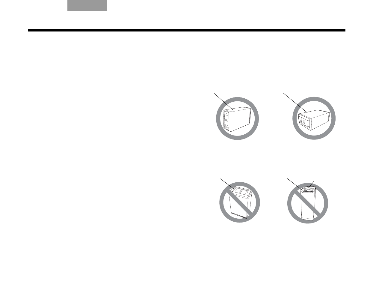
TAB 5Español TAB 6 TAB 8TAB 7English TAB 3Español
ÓPTIMO
Para conseguir una ventilación
óptima, apoye el módulo sobre
su superficie inferior, como se
muestra arriba.
ALTERNATIVA
Apoye el módulo sobre
uno de sus dos lados
anchos.
Superficie superior
Superficie lateral
NO
apoye el módulo sobre el
extremo que presenta una
suave curvatura, ya que
podría caerse.
NO
apoye el módulo sobre la rejilla
frontal. El peso del módulo
puede dañar la rejilla.
Extremo posterior
Extremo frontal
Aberturas de
ventilación
INSTALACIÓN
Ubicación del módulo Acoustimass
Coloque las patas de goma autoadhesivas en la
superficie que está en contacto con el piso (uno de los
lados, la parte superior o la inferior).
Sitúe el módulo Acoustimass®:
• En el mismo extremo de la habitación que los
altavoces frontales.
• A un mínimo de 45 cm (18 pulgadas) del televisor
para evitar interferencias magnéticas en la imagen de
televisión.
• Con el extremo frontal orientado hacia la habitación.
• Al alcance del cable de entrada de audio, de los
cables de los cinco altavoces y de la toma de CA de
la red eléctrica.
• Bajo una mesa o detrás de un armario, pero no
donde las aberturas del módulo puedan quedar
bloqueadas por muebles o cortinas.
• Sobre los dos lados, la parte superior o la inferior
(Figura 9).
NO coloque el módulo Acoustimass:
• Sobre su extremo posterior o frontal (Figura 9).
• Donde las ranuras de ventilación de los circuitos
electrónicos incorporados queden bloqueadas.
®
• Donde queden expuestos los soportes electrónicos,
como las cintas, a su campo magnético durante
periodos prolongados.
• Donde el extremo frontal esté orientado a una pared.
Figura 9 Colocación correcta e incorrecta del módulo Acoustimass
13
Page 86

INSTALACIÓN
AM
FM Base de AM
EnglishTAB 6TAB 8 TAB 7 TAB 3TAB 5 EspañolEspañol
Conexiones de antena
Las antenas de AM y FM suministradas se conectan al
panel posterior del centro de medios (Figura 10).
Nota: El conector de FM puede utilizarse con una
antena exterior. Antes de realizar esta operación, consulte
a un instalador cualificado. Siga todas las instrucciones
de seguridad que se incluyen con la antena.
Figura 10 Conexión de las antenas de AM y FM
Conexión de la antena de FM
1. Enchufe el conector del cable de antena dipolo de
FM en la toma de antena de FM.
2. Despliegue los brazos de la antena y cambie su
orientación si es necesario para conseguir una
recepción de FM óptima.
3. Mantenga la antena lo más alejada posible del
centro de medios, la pantalla y el módulo
Acoustimass
®
.
Conexión de la antena de AM
1. Enchufe el conector del cable de la antena de
cuadro de AM en la toma de antena de AM.
2. Coloque la antena de AM sobre la base o monte la
antena sobre una pared siguiendo las
instrucciones suministradas con la antena de AM.
3. Mantenga la antena lo más lejos posible (como
mínimo 50 cm o 20 pulgadas) del centro de medios
y del módulo de visualización, y un mínimo de 60
cm (2 pies) del módulo de Acoustimass.
Nota: La recepción de AM puede verse afectada por la
presencia de un televisor encendido en las proximidades.
Apague el televisor para conseguir una recepción óptima
de AM.
Cable de radio opcional
Algunos proveedores de televisión por cable ofrecen
señales de radio FM por medio del servicio de cable. Este
cable se conecta a la toma de antena de FM situada en el
panel posterior del centro de medios.
Para obtener instrucciones de conexión, póngase en
contacto con su proveedor de televisión por cable.
14
Page 87

TAB 5Español TAB 6 TAB 8TAB 7English TAB 3Español
Centro de medios
Toma d e l s e n sor
INSTALACIÓN
Instalación del sensor de
encendido/apagado del televisor
El sensor de encendido/apagado del televisor permite al
sistema encender el televisor de manera automática
cuando se selecciona otra fuente de vídeo (DVD, receptor
de cable o satélite, etc.). Si decide no utilizar el sensor,
deberá apagar el televisor por separado.
En el caso de los televisores más grandes, quizá necesite
la ayuda de otra persona para dar los pasos siguientes:
Nota: Es posible que los proyectores frontales con
pantalla independiente no funcionen con el sensor.
Figura 11 Sensor de encendido/apagado del televisor situado en el televisor
1. Enchufe el conector del cable del sensor en el
conector TV SENSOR del centro de medios.
Si utiliza un adaptador SCART, conecte el sensor
directamente al conector de paso suministrado en
el adaptador (Figura 12 en la página 17).
2. Coloque temporalmente el sensor de encendido/
apagado del televisor en la parte posterior del
televisor (Figura 11).
Nota: NO fije la brida de montaje suministrada hasta que
haya probado y activado la función automática como se
explica a continuación.
15
Page 88

INSTALACIÓN
EnglishTAB 6TAB 8 TAB 7 TAB 3TAB 5 EspañolEspañol
3. Encienda el televisor utilizando el mando a
distancia del televisor.
4. Presione System en el mando a distancia
Lifestyle
®
.
5. Para moverse a la derecha al menú Configuración
, presione la flecha derecha y luego
presione ENTER.
6. Baje hasta Encendido TV
presionando la flecha
abajo y luego presione ENTER.
7. Suba o baje para seleccionar la opción correcta de
Encendido TV que detecte el sensor del televisor:
• Automático (para los modelos de televisión que
no utilizan un conector europeo SCART)
• Euro Conector (para los modelos de televisión
que utilizan un conector europeo SCART)
8. Presione ENTER.
Por debajo del elemento resaltado Encendido TV
se encuentra Estado del encendido TV. El valor de
este elemento cambia de No detectado a TV
encendido, cuando el sensor está correctamente
colocado.
Nota: En el paso siguiente es conveniente recurrir a un
ayudante, que verá la pantalla mientras usted mueve el
sensor.
9. Sujete el sensor contra la parte posterior del
televisor y muévalo lentamente alrededor hasta
que Estado del encendido TV cambie de
No detectado a TV encendido.
10. Cuando Estado del encendido TV indica
TV encendido, presione Exit para salir del
menú Sistema.
De este modo terminará la activación del sensor.
16
Page 89

TAB 5Español TAB 6 TAB 8TAB 7English TAB 3Español
Uso de un adaptador SCART (sólo Europa)
El adaptador SCART se conecta al centro de medios empleando los cinco conectores mostrados abajo.
Figura 12 Conexiones de vídeo compuesto SCART
INSTALACIÓN
17
Page 90

INSTALACIÓN
EnglishTAB 6TAB 8 TAB 7 TAB 3TAB 5 EspañolEspañol
Conexión del audio del televisor
Puede conectar un componente de fuente, como una
videocámara o consola de juegos, directamente al
televisor. Para reproducir el audio de esa fuente a través
del sistema Lifestyle
del televisor al sistema Lifestyle
Si el televisor no tiene una salida de audio, podrá oír el
sonido de un componente conectado a través de los
altavoces integrados en el televisor. Sin embargo, en
cualquier otro momento es mejor mantener el volumen
del televisor bajado al máximo para conseguir una mejor
experiencia de sonido envolvente.
®
, deberá conectar el audio que sale
®
.
Para conectar el audio del televisor al sistema
Lifestyle
• Para una conexión básica de audio analógico, utilice
el cable de audio estéreo suministrado (con dos
conectores RCA en cada extremo, uno rojo y otro
blanco). Este cable conecta las salidas de audio
izquierda (L) y derecha (R) del panel posterior del
televisor a las entradas de audio marcadas como L y
R para televisión del panel posterior del centro de
medios (Figura 13).
• Si su televisor proporciona un conector de salida de
audio digital, conecte un cable de audio digital.
Cuando realice la conexión de audio digital, utilice un
cable coaxial o un cable óptico.
No desconecte la conexión analógica descrita arriba.
La conexión analógica garantiza un sonido
consistente en el caso de que la señal digital
sea débil.
• Si el televisor dispone de salidas de audio fijas (FIX) y
variables (VAR), utilice las salidas fijas para obtener
mayor calidad. Asegúrese de seleccionar Fijas en el
menú de configuración de su televisor.
®
:
18
Page 91

Figura 13 Conexión de audio entre el televisor y el centro de medios
TAB 5Español TAB 6 TAB 8TAB 7English TAB 3Español
INSTALACIÓN
19
Page 92

INSTALACIÓN
EnglishTAB 6TAB 8 TAB 7 TAB 3TAB 5 EspañolEspañol
Uso del emisor de infrarrojos
Los emisores de infrarrojos permiten que el sistema
controle dispositivos de fuente, incluso aunque se
encuentren en un armario, múltiples estantes u ocultos.
Deberá colocar un emisor de infrarrojos en todos los
dispositivos que desee controlar utilizando el mando a
distancia Lifestyle
Para utilizar un emisor de infrarrojos con un
dispositivo
1. Enchufe el conector del cable del emisor de
infrarrojos en el conector del emisor de
infrarrojos del centro de medios Lifestyle
2. Coloque el emisor de modo que el lado plano se
sitúe contra el panel frontal del dispositivo fuente.
3. Utilizando la brida adhesiva suministrada, conecte
el emisor al dispositivo.
®
.
®
.
Figura 14 Emisores de infrarrojos situados en el panel
frontal del dispositivo
20
Page 93

TAB 5Español TAB 6 TAB 8TAB 7English TAB 3Español
INSTALACIÓN
Para utilizar emisores de infrarrojos con dos o
más dispositivos
1. Enchufe el conector del alargador del emisor de
infrarrojos al centro de medios Lifestyle
2. Enchufe el conector del cable del emisor de
infrarrojos (o alargadores externos) al alargador del
emisor de infrarrojos.
3. Coloque cada emisor de modo que el lado plano
se sitúe contra el panel frontal de cada dispositivo.
4. Utilizando la brida adhesiva suministrada, conecte
los emisores a los dispositivos.
Nota: Puede utilizar hasta cuatro emisores de infrarrojos
con el sistema.
Si necesita alargadores de emisor de infrarrojos
adicionales, póngase en contacto con Atención al cliente
de Bose
®
. Consulte la hoja de direcciones incluida en
la caja.
®
.
Figura 15 Emisores de infrarrojos situados en el panel
frontal del dispositivo
21
Page 94

CONTROLES E INDICADORES
Silenci
Vol -
Vol +
EnglishTAB 6TAB 8 TAB 7 TAB 3TAB 5 EspañolEspañol
La pantalla
La pantalla muestra mensajes del sistema, lo que
incluye detalles del programa, la fuente que se está
reproduciendo y la opción seleccionada.
Figura 16 Pantalla del sistema Lifestyle
®
Los botones de la parte superior de la pantalla
controlan las funciones básicas del sistema Lifestyle
Enciende y apaga el sistema. Si está activado
®
Bose
link y mantiene presionado este botón,
se apagarán todas las zonas. (Consulte
“Configuración de una segunda habitación
con sonido” en la página 53.)
Recorre las selecciones de fuentes
disponibles.
Silencia los altavoces de la habitación
principal.
Si está activado Bose
®
link y mantiene
presionado este botón, se silenciarán los
altavoces de todas las habitaciones.
(Consulte “Configuración de una segunda
habitación con sonido” en la página 53.)
Baja el volumen de audio de los altavoces.
Sube el volumen de audio de los altavoces.
®
.
22
Page 95

TAB 5Español TAB 6 TAB 8TAB 7English TAB 3Español
CONTROLES E INDICADORES
Mando a distancia
El mando a distancia avanzado de radiofrecuencia
funciona desde casi cualquier lugar de la casa. No es
necesario apuntar con el mando a distancia hacia la
pantalla.
Además de controlar su sistema Lifestyle
distancia se puede programar para controlar todos los
dispositivos fuente conectados al sistema.
En las páginas siguientes se explica la función de cada
botón del mando a distancia. La programación del
mando a distancia se trata según la actividad de este
modo:
• “Televisión” en la página 30
• “Controlar un receptor de cable o satélite” en la
página 32
• “Control de la reproducción de DVD” en la página 34
• “Configuración para ver cintas de vídeo” en la
página 36
• “Configuración de una fuente auxiliar (AUX)” en la
página 38
• “Uso de la radio” en la página 44
®
, el mando a
Figura 17 Mando a distancia Lifestyle
®
23
Page 96

CONTROLES E INDICADORES
EnglishTAB 6TAB 8 TAB 7 TAB 3TAB 5 EspañolEspañol
Las descripciones de los botones del mando a
distancia se organizan por su función general en las
páginas siguientes. Es posible que algunos botones no
se encuentren agrupados físicamente. Consulte su
mando a distancia mientras lee las siguientes
descripciones sobre los botones.
Para que muchos de los botones puedan funcionar
correctamente, el mando a distancia Lifestyle
®
debe
configurarse para controlar la fuente seleccionada.
Consulte “Funcionamiento” comenzando en la
página 30.
Nota: Una fuente es cualquier dispositivo, como un
reproductor de DVD, que emita vídeo y/o audio y pueda
conectarse a su sistema Lifestyle
®
.
Botones de alimentación y selección de fuente
On/Off
Lifestyle
utilizada al encender el sistema. Si está
activado Bose
– Enciende y apaga el sistema
®
, seleccionando la última fuente
®
link y mantiene presionado
este botón, se apagarán todas las zonas.
(Consulte “Configuración de una segunda
habitación con sonido” en la página 53.)
• TV – Enciende el sistema Lifestyle
estaba apagado. Selecciona TV como
fuente.
• On/Off – Enciende y apaga el televisor.
• Input – Selecciona diferentes
conectores de vídeo del televisor.
Mute – Silencia o activa el volumen.
Si está activado Bose
®
link y mantiene
presionado este botón, se silenciarán los
altavoces de todas las habitaciones.
(Consulte “Configuración de una segunda
habitación con sonido” en la página 53.)
• CBL-SAT – Selecciona el dispositivo
fuente enchufado a los conectores
CBL-SAT. Enciende el sistema Lifestyle
si estaba apagado.
• On/Off - Enciende o apaga el receptor
del cable o satélite.
®
si
®
24
Page 97

TAB 5Español TAB 6 TAB 8TAB 7English TAB 3Español
CONTROLES E INDICADORES
• DVD – Selecciona el dispositivo fuente
enchufado a los conectores de DVD.
Enciende el sistema Lifestyle
®
si estaba
apagado.
• On/Off - Enciende y apaga el DVD.
• AUX – Selecciona el dispositivo fuente
enchufado a los conectores AUX.
Enciende el sistema Lifestyle
®
si estaba
apagado.
• On/Off – Enciende y apaga el
dispositivo AUX.
• VCR – Selecciona el dispositivo fuente
enchufado a los conectores VCR.
Enciende el sistema Lifestyle
®
si estaba
apagado.
• On/Off - Enciende y apaga el VCR.
FM - Selecciona el sintonizador de radio
FM/AM incorporado con la última emisora
seleccionada. Enciende el sistema
Lifestyle
®
si estaba apagado.
AM - Selecciona el sintonizador de radio
AM incorporado con la última emisora
seleccionada. Enciende el sistema
Lifestyle
®
si estaba apagado.
Menú y navegación botones
Configuración - Entra o sale del menú
Configuración de la fuente actual.
Info - Muestra u oculta la información de
televisión, receptor de cable o satélite o
reproductor de vídeo/DVR en la pantalla del
televisor (cuando el televisor, receptor de
cable o satélite o reproductor de vídeo/DVR
suministran esta función).
Sistema - Entra o sale del menú principal
Sistema.
Menu – Muestra el menú de opciones de la
fuente actual (cuando el televisor, receptor
de cable o satélite o reproductor de vídeo/
DVR suministran esta función).
Exit
• Sale de los menús Configuración y
Sistema.
• Sale de los menús en pantalla para
televisión, receptor de cable o satélite o
reproductor de vídeo/DVR (cuando el
televisor, receptor de cable o satélite o
reproductor de vídeo/DVR suministran
esta función).
25
Page 98

CONTROLES E INDICADORES
EnglishTAB 6TAB 8 TAB 7 TAB 3TAB 5 EspañolEspañol
Tune Up/Down
• Sintoniza la radio FM/AM hacia
arriba o hacia abajo en la siguiente
frecuencia.
• Selecciona el elemento anterior o
siguiente de la lista del menú.
Enter - Confirma la selección de un
elemento de menú.
Teclas de flecha – Sirven para
subir, bajar, ir la izquierda o a la
derecha en un menú o una pantalla.
Guide – Muestra una guía electrónica de
programación (cuando el televisor, el
receptor de cable o satélite o el VCR/DVR
proporcionan esta función).
Page Up/Down – Indica al televisor o al
receptor de cable o satélite que suban o
bajen una página en una guía en pantalla.
Volume – Sube o baja el volumen.
• Si presiona + subirá el volumen y se
activará el sonido del sistema (si
estaba silenciado).
•Presione
Channel/Track– Retrocede o avanza
al siguiente canal de televisión, cable
o satélite, pista de CD o capítulo
de DVD.
–
para bajar el volumen.
26
Page 99

TAB 5Español TAB 6 TAB 8TAB 7English TAB 3Español
CONTROLES E INDICADORES
Modo de reproducción y botones numéricos
Stop
• Detiene la reproducción de música
(salvo FM/AM) o de vídeo.
• El sistema inserta un marcador donde
se detiene el disco para poder
reanudar la reproducción en el mismo
sitio, si su reproductor admite esta
función (sólo en los DVD y VCD). Si se
vuelve a pulsar, se borrará la señal.
Pause - Realiza una pausa en la
reproducción de música (salvo FM/AM) o
de vídeo.
Play - Comienza a reproducir la música
(salvo FM/AM) o el vídeo.
Scan
• Retrocede o avanza en el vídeo.
Muestra una barra de control
para ajustar la velocidad de este
movimiento.
• Pasa a la siguiente o anterior
pista del CD o emisora de radio
con suficiente potencia.
Cuando se mantiene pulsado,
explora hacia atrás y hacia delante
el CD o disco MP3 actual.
Repeat
• Repite la selección de música actual
de un CD. Si vuelve a presionar se
cancelará la repetición.
• Avanza unos segundos en su DVR.
27
Page 100

CONTROLES E INDICADORES
EnglishTAB 6TAB 8 TAB 7 TAB 3TAB 5 EspañolEspañol
Grabar
• Activa la grabación en un dispositivo
de grabación.
Comb aleat
• Reproduce música de un CD de
manera aleatoria. Si vuelve a
presionar se cancelará la repetición.
• Retrocede unos segundos en su DVR.
Teclas numéricas - Seleccionan
la preselección de emisora de
radio, el capítulo de DVD, la pista
de CD o el canal de televisión que
corresponda al número pulsado.
Previous – Pasa al último canal
seleccionado en el televisor, el receptor
de cable o satélite, el VCR o el DVR (en
su caso).
Botones de configuración de la imagen botones
Imagen en imagen – Activa la función de
imagen en imagen en su televisor (si incluye
esta función).
Vista de imagen– Permite especificar cómo
aparecerán determinados formatos de
imagen de su sistema Lifestyle
®
en la
pantalla HDTV.
28
 Loading...