

Page 1
SHOWMATCH SYSTEMS
USAGE AND APPLICATION GUIDE
Page 2

WELCOME
SHOWMATCH SYSTEMS
USAGE AND APPLICATION GUIDE
From small ground-stacked setups in modest venues
to outdoor music festivals and arena-scale events,
ShowMatch DeltaQ systems can be found all around the
world in a variety of sound reinforcement applications.
ShowMatch loudspeakers deliver outstanding
vocal clarity with consistent frequency
response and sound pressure level across a
defined coverage area. And with integrated
DeltaQ technology you can ensure consistent
performance across the entire audience area at any venue.
Adaptable and scalable, ShowMatch loudspeakers are the
ideal solution for rental and staging market applications.
When an event calls for lower SPL capabilities in a more
compact format, simply build a smaller ShowMatch array
with the same vertical coverage as larger, higher-powered
ShowMatch setups.
About this guide
We oer a complete integrated suite of software design
tools, digital signal processing, tour-ready amplifier racks
and transportation accessories to support ShowMatch
loudspeakers. This guide gives an overview of them.
Optimized for use in the demanding rental and staging
environment, ShowMatch system solutions allow you to
easily transport, set up, configure and use ShowMatch
loudspeakers in the fast-paced environment of the
entertainment production industry. ShowMatch systems
enable rental sound and A/V production service providers
to give their clients a brand they know and trust, while
delivering outstanding audio quality for a wide range of
field applications.
Rock al Parque, Bogotá, Colombia
ShowMatch system owner – Illuminacion, Jaime Dussan
TABLE OF CONTENTS
Safety Information ...................................................................................................................................................................................................2
ShowMatch System Components .................................................................................................................................................................... 7
SM5, SM10, SM20, SMS118 .............................................................................................................................................................................................................7
Connections and Wiring .......................................................................................................................................................................................8
Full-range modules ........................................................................................................................................................................................................................ 8
Amplification ............................................................................................................................................................................................................... 8
Recommended Amplification for Rental/Production Applications ............................................................................................................................9
Recommended Signal Processing for Rental/Production .............................................................................................................................................. 9
Recommended Amplification for Installed Applications ...............................................................................................................................................10
Economy Setting ...........................................................................................................................................................................................................................10
Performance Setting .....................................................................................................................................................................................................................11
Recommended Signal Processing for Permanent Installations ................................................................................................................................... 12
Designing ShowMatch Systems .......................................................................................................................................................................13
System Concept ............................................................................................................................................................................................................................. 13
System Software ......................................................................................................................................................................................................15
EASE Focus ......................................................................................................................................................................................................................................15
PowerSoft ArmoníaPlus ..............................................................................................................................................................................................................16
Example 1: Outdoor Live Music Example 1 ...........................................................................................................................................................................17
Example 2: Outdoor Live Music Example 2 .........................................................................................................................................................................18
Example 3: Indoor Live Music Example 1 ..............................................................................................................................................................................19
Example 4: Indoor Live Music Example 2 ...........................................................................................................................................................................20
Example 5: Corporate AV Example 1 ......................................................................................................................................................................................21
Example 6: Corporate AV Example 2 ...................................................................................................................................................................................22
ShowMatch Tour Rack ......................................................................................................................................................................................... 23
ShowMatch Tour Rack Configuration ...................................................................................................................................................................................23
Input Priority and Routing ........................................................................................................................................................................................................23
Initial System Configuration ..................................................................................................................................................................................................... 23
Initial System Loudspeaker Configurations ........................................................................................................................................................................ 24
Input Configurations ....................................................................................................................................................................................................................25
Loudspeaker Connections ........................................................................................................................................................................................................25
ShowMatch Tour Rack Connection ..............................................................................................................................................................26
ShowMatch System Presets ............................................................................................................................................................................. 29
ShowMatch Array Presets ......................................................................................................................................................................................................... 29
ShowMatch Module Presets .....................................................................................................................................................................................................30
ShowMatch Subwoofer Presets ............................................................................................................................................................................................... 31
ShowMatch Cardioid Presets .................................................................................................................................................................................................... 31
ShowMatch Transportation Accessories .................................................................................................................................................... 32
Truck Pack Information ..............................................................................................................................................................................................................34
ShowMatch Suspension Hardware ............................................................................................................................................................... 35
ShowMatch Array Frame (SMAF) .......................................................................................................................................................................................... 35
ShowMatch T-Bar Array Frame (SMAFT) ...........................................................................................................................................................................36
ShowMatch Array Pullback Bracket (SMPULL) ................................................................................................................................................................ 37
Array Suspension ................................................................................................................................................................................................... 39
Connect Array Frame to Subwoofer .................................................................................................................................................................................... 40
Connect Pull Back Bracket to Full-range Module ............................................................................................................................................................. 41
Center Rail Suspension Using the Array Frame Multipoint Bracket .........................................................................................................................42
Ground Stack Arrays Installation ................................................................................................................................................................... 42
Product Dimensions ....................................................................................................................................................................................................................43
Adjust Ground Stack Bracket Angle ..................................................................................................................................................................................... 43
Attach Ground Stack Bracket to ShowMatch SMS118 ....................................................................................................................................................44
Attach Ground Stack Bracket to ShowMatch Array Frame .........................................................................................................................................45
ShowMatch System Reference Guide .........................................................................................................................................................46
System Testing ...............................................................................................................................................................................................................................46
Measurement Set Up ...................................................................................................................................................................................................................46
ShowMatch Loudspeakers Technical Specifications.......................................................................................................................................................47
ShowMatch Systems Service and Repair Parts List ........................................................................................................................................................48
PRO.BOSE.COM
1
Page 3

SAFETY INFORMATION
Important Safety Instructions
1. Read these instructions.
2. Heed all warnings.
3. Do not use this apparatus near water.
4. Clean only with a dry cloth.
5. Refer all servicing to qualified service personnel. Servicing is required when the apparatus has been damaged
in any way, such as power supply cord or plug is damaged, liquid has been spilled or objects have fallen into the
apparatus, the apparatus has been exposed to rain or moisture, does not operate normally, or has been dropped.
Visual Inspection and Maintenance of Components
Bose ShowMatch systems should be assembled, installed and suspended by expert, trained personnel who are
experienced in suspending loudspeaker systems of this type. Prior to suspending or mounting any loudspeaker
system, always inspect all components (suspension frames and hardware, enclosures, brackets, pins, eyebolts, etc.)
for corrosion, deformation, cracks or missing parts that could compromise the strength and safety of the loudspeaker
system being suspended. Do not suspend or mount the system until corrective action has been taken.
Installed systems should be regularly inspected to determine that load-bearing elements do not exhibit any condition
which may compromise the strength and safety of the suspended loudspeaker system, or as required by local
regulations.
The components used in suspending a ShowMatch system must be load rated for the intended use. Suspension
hardware can be obtained from industrial supply catalogs and specialized distributors. Hardware intended for overhead
use will comply with ASME B30.20 and will be manufactured according to product traceability procedures. Hardware of
this type will have a specified working load limit (WLL).
For all other materials used in the suspension of ShowMatch systems, refer to the hardware manufacturer’s inspection
and maintenance guidelines.
Bose Professional is not responsible for the application of its products for any purpose, or the misuse of this
information. Furthermore, Bose Professional is not responsible for the conditions arising from avoiding regular
maintenance and inspections, or any other abuse condition.
Attachment to Structures
ShowMatch system installations should utilize a licensed Professional Engineer who is familiar with local building
and seismic codes as it applies to the suspension of objects from building structures. The hardware and methods of
installation must conform to the specifications of the Professional Engineer retained for the project. Failure to install
components in the manner specified may result in damage, injury or death.
Important Safety Instructions
Please read this installation guide carefully and save it for future reference.
This product is intended for installation by professional installers only! This document is intended to provide professional installers with basic installation
and safety guidelines for this product in typical fixed-installation or portable-system applications. Please read this document and all safety warnings
before attempting installation.
WARNINGS:
All Bose products must be installed in accordance with local, state, federal and industry regulations. It is the installer’s responsibility to
ensure installation of the loudspeakers and mounting system is performed in accordance with all applicable codes, including local building
codes and regulations. Consult the local authority having jurisdiction before installing this product.
Unsafe mounting or overhead suspension of any heavy load can result in serious injury or death, and property damage. It is the
responsibility of the installer to evaluate the reliability of any mounting method used for their application. Only professional installers with
the knowledge of proper hardware and safe mounting techniques should attempt to install any loudspeaker overhead.
CAUTION:
Installed loudspeaker arrays require regular inspection and routine maintenance to ensure proper function and
safe operation. Inspect mounting hardware and attachments for signs of corrosion, bending or any other condition that may decrease the
structural integrity. Immediately replace worn or damaged components.
Do not make unauthorized alterations to this product; doing so may compromise safety, regulatory compliance, system performance, and
may void the warranty.
Never exceed 24 ShowMatch full-range or 18 ShowMatch subwoofer modules using the integrated suspension system for arrays. Please
refer to product labels for Working Load Limit data.
Visual Inspection and Maintenance of Components
Bose ShowMatch systems should be assembled, installed and suspended by expert, trained personnel who are experienced in suspending
loudspeaker systems of this type. Prior to suspending or mounting any loudspeaker system, always inspect all components (suspension
frames and hardware, enclosures, brackets, pins, eyebolts, etc.) for corrosion, deformation, cracks or missing parts that could compromise
the strength and safety of the loudspeaker system being suspended. Do not suspend or mount the system until corrective action has
been taken.
Installed systems should be regularly inspected to determine that load-bearing elements do not exhibit any condition which may
compromise the strength and safety of the suspended loudspeaker system, frequency of inspection, or as required by local regulations.
The components used in suspending a ShowMatch system must be load rated for the intended use. Suspension hardware can be obtained
from industrial supply catalogs and specialized distributors. Hardware intended for overhead use will comply with ASME B30.20 and will be
manufactured according to product traceability procedures. Hardware of this type will have a specified working load limit (WLL).
For all other materials used in the suspension of ShowMatch systems, refer to the hardware manufacturer’s inspection and maintenance
guidelines.
Bose Professional is not responsible for the application of its products for any purpose, or the misuse of this information. Furthermore,
Bose Professional is not responsible for the conditions arising from avoiding regular maintenance and inspections, or any other
abuse condition.
Attachment to Structures
ShowMatch system installations should utilize a licensed Professional Engineer who is familiar with local building and seismic codes as it
applies to the suspension of objects from building structures. The hardware and methods of installation must conform to the specifications
of the Professional Engineer retained for the project. Failure to install components in the manner specified may result in damage, injury
or death.
Note: Always use recommended software to confirm safe working load limits with exact array configurations, pitch angles, and connection points.
Guidelines for Installation and Setup of ShowMatch DeltaQ Array Module Loudspeakers
Installation information contained in this document is only a general guideline and cannot, as such, represent all requirements and precautions.
Accordingly, anyone using this material assumes all liability and is expressly responsible for the safety of all loudspeaker array designs and mounting
configurations applied in practice.
Prior to the installation or portable-system setup of any overhead loudspeaker, a licensed Professional Engineer must approve the location and method
of attachment to the building structure or support-truss structure and confirm they are consistent with all building codes and regulations. Ensure the
mounting surface and the method of attaching the loudspeaker system to the surface is capable of supporting the total weight of the system. A safety
factor of 10:1 is recommended.
Obtain all mounting system components from reputable manufacturers. Select a mounting system appropriate for your loudspeaker system and its
intended application. We recommend Bose mounting accessories when available. A licensed professional engineer must review the design and fabrication
of any custom mounting hardware.
Bose ShowMatch array module loudspeakers feature an integrated quick-pin suspension system, designed to facilitate loudspeaker array mounting by
professional installers. Module to module connections should be made using only the integrated suspension link-bars with the included or optional loadrated “quick pin” fasteners. Unmarked (not rated for load bearing) fasteners should not be used.
Do not suspend loudspeaker using handles as attachment points. Handles are NOT designed for load bearing!
Use a safety cable, separately attached to the cabinet, at a point not in common with the load bearing attachment points of the mounting system to
the loudspeaker. This is recommended even if not required by local regulation. Consult a licensed Professional Engineer or a suspension professional for
proper design and installation.
Do not under any circumstances climb the array.
2 3
PRO.BOSE.COMPRO.BOSE.COM
Page 4

Instrucciones de Seguridad Importantes Instructions Importantes Relatives à la Sécurité
Lea detenidamente esta guía de instalación y consérvela para consultarla en el futuro.
Este producto está diseñado para que solo instaladores profesionales realicen su instalación. Este documento está diseñado para proveer las pautas de
seguridad e instalación básicas a los instaladores profesionales de este producto en aplicaciones de sistema portátil e instalación fija comunes. Lea este
documento y todas las advertencias de seguridad antes de comenzar la instalación.
ADVERTENCIAS:
Todos los productos Bose
instalador garantizar que la instalación del sistema de soporte y los altavoces se realice conforme a los códigos aplicables, incluidos los
códigos y las reglamentaciones de construcción locales. Consulte a la autoridad local competente antes de instalar este producto.
El montaje inseguro o la suspensión en alturas de cualquier carga pesada puede provocar lesiones graves o la muerte, además de daños a
la propiedad. Es responsabilidad del instalador evaluar la fiabilidad de cualquier método de montaje utilizado para su aplicación. Solo los
instaladores profesionales con el conocimiento de los componentes físicos adecuados y las técnicas de montaje seguro deberían intentar
instalar cualquier altavoz en altura.
PRECAUCIÓN:
Se deben inspeccionar regularmente los arreglos instalados de altavoz, además de realizarles mantenimiento de rutina con el propósito de
garantizar su funcionamiento adecuado y
operación segura. Revise los accesorios y los componentes físicos para instalación, y busque signos de corrosión, torcimiento o cualquier
otra condición que pueda disminuir la integridad estructural. Sustituya inmediatamente los componentes desgastados o dañados.
Solo realice alteraciones autorizadas a este producto. De lo contrario, podría comprometer la seguridad, el cumplimiento de las
reglamentaciones y el rendimiento del sistema; además, podría anular la garantía.
Nunca exceda 24 módulos de rango completo ShowMatch o 18 módulos de subwoofer ShowMatch usando el sistema de montaje integrado
para los arreglos. Consulte las etiquetas de producto para obtener información sobre los datos del límite de carga de trabajo.
Nota: Utilice siempre el software Modeler o “Bose Array Tool” para confirmar los límites de seguridad de carga de trabajo con cada configuración del
arreglo, ángulos de inclinación y los puntos de conexión.
Pautas de instalación y configuración de los altavoces de arreglo modular ShowMatch DeltaQ
La información de instalación incluida en este documento solo corresponde a pautas generales y, como tal, no puede representar todos los requisitos
ni todas las precauciones. Por lo tanto, todo aquel que utilice este material asume toda la responsabilidad y es expresamente responsable de todos los
diseños de arreglo y las configuraciones de montaje del altavoz realizadas en la práctica.
Antes de la instalación o la configuración del sistema portátil de cualquier altavoz en altura, un ingeniero profesional licenciado debe aprobar la
ubicación y el método de fijación a la estructura del inmueble o a la estructura colgante, y confirmar que sean compatibles con todos los códigos y las
reglamentaciones de construcción. Asegúrese de que la superficie de montaje y el método de fijación a la superficie del sistema de altavoces pueda
soportar el peso total del sistema. Se recomienda un factor de seguridad de 10:1.
Obtenga todos los componentes de montaje del sistema de fabricantes acreditados. Seleccione un sistema de montaje adecuado para su sistema de
altavoz y su aplicación prevista. Recomendamos que utilice accesorios de montaje de Bose si están disponibles. Un ingeniero profesional licenciado debe
revisar el diseño y la fabricación de todos los componentes físicos personalizados para la instalación.
Los altavoces modulares ShowMatch incluyen un sistema de montaje de conexión rápida diseñado para facilitar el trabajo de los instaladores
profesionales. Las conexiones modulares se deben realizar solo con las barras de conexión de montaje y las sujeciones de conexión rápida de carga
incluidos u opcionales. No se deben utilizar sujeciones sin marcas (no aptas para soportar cargas).
No utilice las asas como puntos de fijación para suspender el altavoz. Las asas NO están diseñadas para soportar la carga.
Utilice un cable de seguridad, unido de forma independiente al gabinete, en un punto distinto del punto de fijación de la carga del sistema de montaje
del altavoz. Esto se recomienda incluso si la reglamentación local no lo requiere. Consulte a un ingeniero profesional licenciado o a profesionales de
andamiaje para realizar un diseño y una instalación adecuados.
Bajo ninguna circunstancia trepe el arreglo.
deben instalarse según las reglamentaciones locales, estatales, federales y del sector. Es responsabilidad del
Consultez attentivement cette notice d’installation et conservez-la pour toute référence future.
L’installation de ce produit doit être eectuée par un technicien professionnel! Ce document à l’intention des installateurs professionnels contient
les directives de pose et de sécurité relatives à ce produit en installation fixe ou dans des applications portables. Veuillez lire ce document, ainsi que
l’ensemble des avertissements de sécurité avant de procéder à l’installation.
AVERTISSEMENTS:
Tous les produits Bose
responsable du respect de tous les codes et règlements locaux et nationaux en vigueur applicables à l’installation et au montage des
enceintes. Consultez les autorités locales compétentes avant d’installer ce produit.
Tout montage non sécurisé d’une lourde charge peut provoquer des dégâts matériels et des blessures graves, voire la mort. Il en va de
la responsabilité de l’installateur d’évaluer la fiabilité de la méthode de montage utilisée, en fonction de l’application. Seul un installateur
professionnel connaissant les accessoires et techniques de montage adaptés est qualifié pour installer des enceintes suspendues.
ATTENTION:
Une fois installées, les systèmes d’enceintes doivent faire l’objet d’une inspection et d’un entretien préventif afin d’assurer
un fonctionnement en toute sécurité. Vérifiez que les composants et les points de fixation ne portent pas de traces de corrosion, de
déformations ou autre signe de détérioration de leur intégrité structurelle. Remplacez immédiatement tout composant usé ou endommagé.
Toute modification non autorisée peut compromettre votre sécurité, le respect des réglementations et le bon fonctionnement de l’appareil,
et en invalidera la garantie.
Ne connectez pas plus de 24modules ShowMatch complets ou 18 caissons de bassesShowMatch au moyen du système de suspension
intégré. Veuillez vous reporter à l’étiquetage des produits pour connaître les limites de charge.
Note: Toujours utiliser le logiciel Bose Modeler
d’orientation et points de connexion.
Instruction d’installation et de configuration du module d’enceintes ShowMatch
Les directives d’installation contenues dans le présent document ne représentent que des conseils généraux et, à ce titre, ne présentent pas tous les
critères et précautions de rigueur. En conséquence, toute personne utilisant ce document assume seule l’entière responsabilité de la sécurité d’installation
de toutes les enceintes et de la configuration pratique de leur montage.
Avant l’installation d’un système portable ou d’une enceinte suspendue, il est nécessaire de faire approuver par un professionnel dûment autorisé
l’emplacement et la méthode de fixation à la structure du bâtiment et de lui faire confirmer que cette fixation est conforme au code du bâtiment et aux
réglementations. Il est important de s’assurer que la surface de montage et la méthode de fixation des enceintes à cette surface sont adaptées au poids
total du système. Par sécurité, il est recommandé de respecter un rapport de poids de 10:1.
Tous les composants du système de montage doivent provenir d’un fabricant de bonne réputation. Le système de montage choisi doit être adapté aux
enceintes et à l’utilisation prévue. Il est recommandé d’utiliser les accessoires de montage Bose disponibles. Faire contrôler par un professionnel qualifié la
conception et la fabrication des accessoires de montage sur mesure.
Le module d’enceintes Array Bose ShowMatch est doté d’un système de suspension par goupilles «quick pin» intégré, destiné à en faciliter le montage
par un installateur professionnel. Les connexions entre modules doivent être réalisées uniquement au moyen des barres de suspension intégrées, avec les
goupilles «quick pin» résistantes à la charge fournies ou en option. Veillez à ne pas utiliser de fixations dont la classe de résistance à la charge n’est pas
indiquée.
Ne pas utiliser les poignées de transport des enceintes comme points de suspension. Ces poignées ne sont pas conçues pour supporter une charge
permanente!
Fixer un câble de sécurité, attaché séparément au coret de l’enceinte, en un point autre que les points de fixation du système de montage de l’enceinte.
Cette mesure est recommandée, même si elle n’est pas imposée par la réglementation locale. Pour la conception et la réalisation de l’installation, consulter
un professionnel agréé.
Ne monter sur le système en aucune circonstance.
doivent être installés dans le respect des réglementations professionnelles, locales et nationales. L’installateur est
ou «Bose Array Tool» pour confirmer les limites sécuritaires d’accrochage ainsi que configurations, angles
4 5
PRO.BOSE.COMPRO.BOSE.COM
Page 5

Wichtige Sicherheitshinweise
Bitte lesen Sie diese Montageanleitung sorgfältig durch und bewahren Sie sie zum späteren Nachschlagen auf.
Dieses Produkt darf nur von fachkundigen Monteuren installiert werden! Dieses Dokument soll fachkundigen Monteuren grundlegende Installations-
und Sicherheitsrichtlinien für dieses Produkt in mobilen und festinstallierten Anwendungen bieten. Bitte lesen Sie dieses Dokument und alle
Sicherheitshinweise vor der Installation durch.
WARNUNG:
Alle Produkte von Bose müssen gemäß lokalen und gesetzlichen Vorschriften sowie gemäß allen Branchenbestimmungen installiert werden.
Der Monteur ist dafür verantwortlich, sicherzustellen, dass die Installation der Lautsprecher und der Halterung gemäß allen geltenden
Vorschriften durchgeführt wird, einschließlich örtlicher Bauvorschriften und -bestimmungen. Wenden Sie sich vor der Installation dieses
Produkts an die zuständige abnehmende Behörde.
Eine unsichere Befestigung schwerer Lasten oder deren Aufhängung über Kopf kann zu schweren oder tödlichen Verletzungen und
Sachschäden führen. Der Monteur ist dafür verantwortlich, die Zuverlässigkeit der für die Anwendung verwendeten Befestigungstechniken
zu prüfen. Nur fachkundige Monteure mit Wissen über sachgemäße Befestigungselemente und sichere Befestigungstechniken sollten
Lautsprecher über Kopf installieren.
VORSICHT:
Installierte Lautsprecher erfordern regelmäßige Überprüfung und Routinewartung, um die ordnungsgemäße Funktion und den sicheren
Betrieb zu gewährleisten. Überprüfen Sie die Befestigungselemente und das Zubehör auf Anzeichen von Korrosion, Verbiegen oder andere
Anzeichen, die die mechanische Stabilität verringern können. Ersetzen Sie abgenutzte oder beschädigte Teile sofort.
Keine nicht autorisierten Veränderungen am Produkt vornehmen. Diese können die Sicherheit, die Einhaltung von Richtlinien und die
Systemleistung beeinträchtigen. In diesem Fall kann die Garantie ungültig werden.
Nutzen Sie das integrierte Array-Verankerungssystem niemals für mehr als 24ShowMatch Fullrange-Module bzw. 18ShowMatch
Subwoofer-Module. Angaben zur zulässigen Traglast entnehmen Sie bitte dem Typenschild.
Anmerkung: Verwenden Sie immer die Bose Modeler
Load Limit) für eine Array-Konfiguration mit gegebenen Neigungswinkeln und Verbindungspunkten zu ermitteln.
Software oder die “Bose Array Tool” Software, um die sicheren Lastbedingungen (Safe Working
SHOWMATCH SYSTEM COMPONENTS
All ShowMatch System modules can be deployed for both fixed installation and portable/rental applications — from
small clubs and houses of worship to outdoor concert venues to performing arts centers and corporate AV productions.
ShowMatch DeltaQ arrays deliver more consistent coverage over a wide frequency range with outstanding vocal and
musical clarity. Each two-way module requires two channels of amplification and associated DSP to provide full-range
response from 59Hz–18 kHz.
Tour-sound output level — 4x Bose EMB2S compression drivers, improved with more HF output, and 2x8-inch
neodymium high-power woofers allow array output up to 145 dB SPL
Three-point “quick-pin” suspension — Fast, easy setup of up to 24 full-range modules with a 10:1 safety factor.
Side suspension guards/handles are easily removed for permanent installations, reducing width and creating a
cleaner visual appearance.
2
Changeable waveguides for the creation of DeltaQ arrays, or arrays with asymmetrical horizontal coverage.
1
.
Richtlinien für die Montage und Inbetriebnahme von ShowMatch Array Modul Lautsprechern
Die in diesem Dokument enthaltenen Installationsinformationen sind nur eine allgemeine Richtlinie und können daher nicht alle Anforderungen und
Vorsichtsmaßnahmen darstellen. Demgemäß übernimmt jeder, der dieses Material verwendet, die gesamte Haftung und ist ausdrücklich verantwortlich für
die Sicherheit aller Lautsprecher-Array-Designs und deren Montagetechniken, die in der Praxis eingesetzt werden.
Vor der Installation oder temporären Inbetriebnahme von Lautsprechern über Kopf muss ein zugelassener fachkundiger Techniker den Ort und die Art der
Befestigung an der Gebäude- bzw. Trägerstruktur prüfen und bestätigen, dass diese allen Bauvorschriften und Bestimmungen entspricht. Vergewissern
Sie sich, dass die Befestigungsfläche und die Art und Weise der Befestigung des Lautsprechersystems an der Fläche geeignet ist, das Gesamtgewicht des
Systems zu tragen. Es wird ein Sicherheitsfaktor von 10:1 empfohlen.
Beschaen Sie sich alle Komponenten der Halterung von zertifizierten Herstellern. Wählen Sie eine Halterung, die für Ihr Lautsprechersystem und die
beabsichtigte Anwendung geeignet ist. Wir empfehlen Befestigungszubehör von Bose, sofern verfügbar. Ein zugelassener fachkundiger Techniker muss
die Auslegung und die Herstellung der benutzerspezifischen Befestigungselemente überprüfen.
Bose ShowMatch Array Modul Lautsprecher verfügen über integrierte Montagepunkte mit Schnellverschlüssen, was die Installation des LautsprecherArrays durch fachkundige Monteure erleichtern soll. Die Module dürfen untereinander ausschließlich mit den integrierten Verbindungsstangen sowie den
im Lieferumfang enthaltenen bzw. optional erhältlichen und für die Last zugelassenen Schnellverschlüssen verbunden werden. Nicht gekennzeichnete
(nicht für das Tragen von Lasten geeignete) Befestigungselemente dürfen nicht verwendet werden.
Hängen Sie die Lautsprecher nicht mithilfe von Grien als Befestigungspunkte auf. Grie sind NICHT als Montagepunkte vorgesehen.
Bringen Sie ein zusätzliches Sicherungsseil an der Box an. Verwenden Sie hierzu nicht die tragenden Befestigungspunkte, die die Halterung mit dem
Lautsprecher verbinden. Wir empfehlen diese Sicherheitsmaßnahme auch dann, wenn diese von den örtlichen Behörden nicht vorgeschrieben ist. Wenden
Sie sich wegen der sachgemäßen Auslegung und Installation an einen zugelassenen fachkundigen Techniker oder ein Fachunternehmen.
Besteigen Sie unter keinen Umständen das Array.
SM5
ShowMatch SM5 full-range array modules provide
5° nominal vertical coverage with included changeable
waveguides oering choice of 70° or 100° horizontal
coverage with optional accessory 55° waveguides.
SM5 modules oer suspension overlap angle adjustment
from 0 to 5°, in 1° increments, to provide increased throw
distance and SPL.
SM5 Accessory Waveguide
The horizontal coverage pattern of ShowMatch
full-range loudspeakers can be changed by
replacing the factory-installed waveguides
with the optional accessory waveguides. The
SM5WG55 waveguide provides 55° horizontal
coverage for
the SM5 loudspeaker.
SM20
ShowMatch SM20 full-range array modules provide 20°
nominal vertical coverage with included changeable
waveguides oering 70° or 100° horizontal coverage and
optional accessory 120° waveguides.
SM20 Accessory Waveguide
The horizontal coverage pattern of ShowMatch
full-range loudspeakers can be changed by
replacing the factory-installed waveguides with
the optional accessory waveguides. The
SM20WG12 waveguide provides 120° horizontal
coverage for the SM20 loudspeaker.
SM10
ShowMatch SM10 full-range array modules provide
10° nominal vertical coverage with included changeable
waveguides oering choice of 70° or 100° horizontal
coverage.
SMS118
ShowMatch SMS118 subwoofers are designed to integrate
with DeltaQ array loudspeakers and extend low-frequency
response down to 29 Hz. The SMS118 enclosure width and
integrated suspension allows fast integration in arrays with
ShowMatch full-range modules using optional array frames
and accessories. The portable-rated Baltic Birch enclosure
may also be used for ground-stack applications.
1
Calculated Peak SPL of 24-module array.
2
Requires the use of short quick pins; Bose PN: 770304-0010.
6 7
PRO.BOSE.COMPRO.BOSE.COM
Page 6
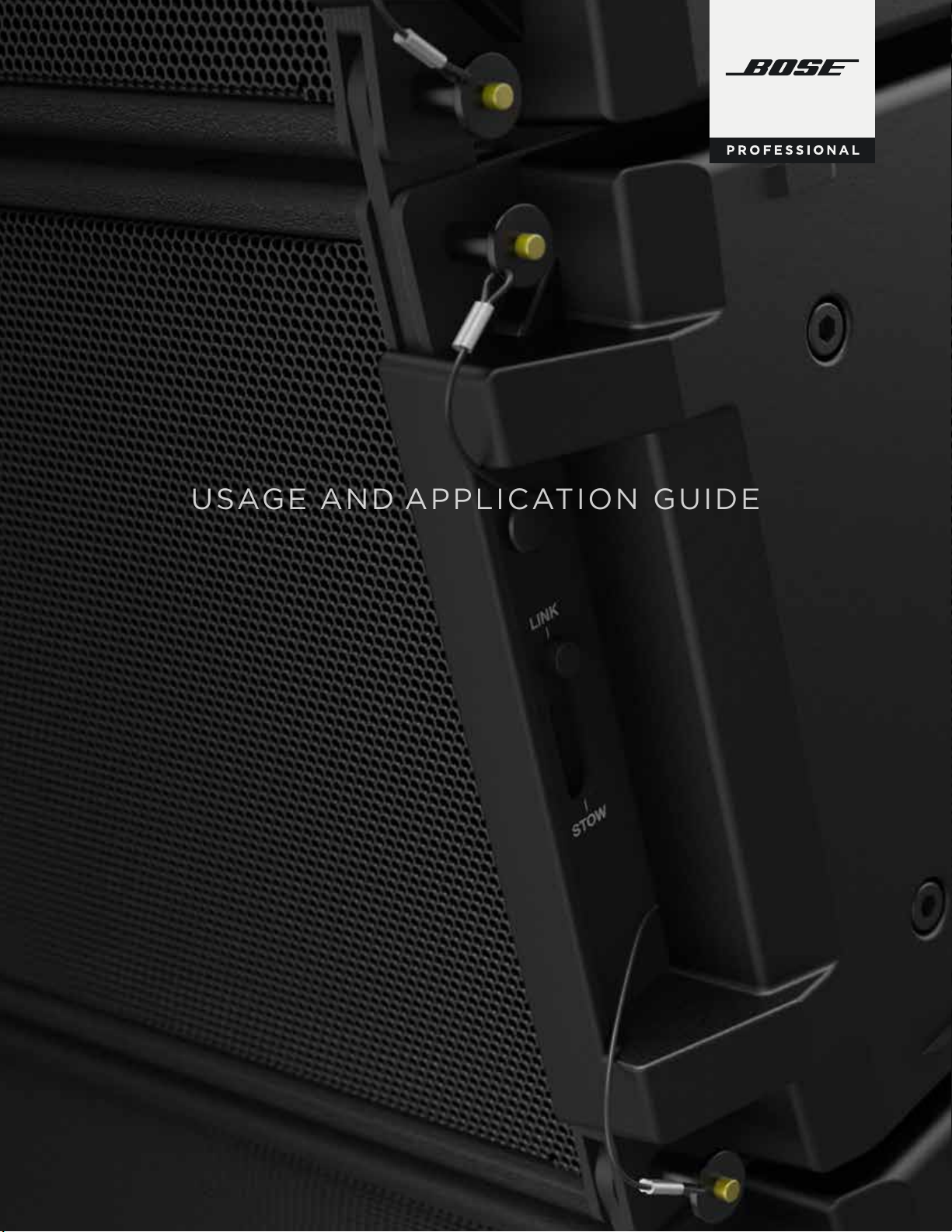
CONNECTIONS AND WIRING
1+
1 -
2+
2-
1+
1 -
2+
2-
1+
1 -
2+
2-
Grille-
mounted
NL4MP
Connector
3-box parallel
(Z min = 2.0 Ω)*
2 subs/channel parallel
(Z min = 2.0 Ω)*
Full-range Modules
1+
1-
2+
SM8
EMB2S
left
}
SM8 right
16 Ω 16 Ω
EMB2S
12 Ω
12 Ω
}
Bi-Amp
LF+ 1+
LF- 1HF+ 2+
HF- 2-
Power Handling
LF: 450 W
HF: 100 W
Impedance
LF: 8 Ω HF: 6 Ω
Parallel
Recommended Amplification for Rental and Production Applications
Bose Professional recommends the use of PowerSoft series amplifiers for rental and production applications.
The ShowMatch Tour Rack includes three PowerSoft x4D amplifiers as the standard building block for a variety
of system configurations.
(See Page 22 for additional information on the ShowMatch Tour Rack.)
3-module parallel
(Z min = 2.0 Ω)
2- subs/channel parallel
(Z min = 2.0 Ω)
EMB2S
EMB2S
2-
Subwoofer Module
1+
1 2+
2-
1+
1 2+
2-
1+
1 2+
2-
Grillemounted
NL4MP
Connector
Discrete
LF+ 1+
LF- 1Thru 2+
Thru 2-
Power Handling
LF: 750 W
Impedance
LF: 4 Ω
Parallel
AMPLIFICATION
ShowMatch full-range modules require two (2) amplifier channels with external DSP active crossover filters (modules
contain no passive crossover network). Each module contains series-parallel connections of four (4) compression
drivers delivering nominal 6-ohm impedance, with a long-term power-handling rating of 100 watts and peak rating
of 400 watts. The low-frequency section contains parallel connections of two (2) woofers delivering nominal 8-ohm
impedance, with a long-term power-handling rating of 450 watts and a peak rating of 1800 watts.
ShowMatch subwoofer modules contain a single 18-inch woofer with nominal 4-ohm impedance, with a long-term
power rating of 750 watts and a peak rating of 3000 watts.
NL4 Channel Breakout
Recommended Signal Processing for Rental and Production
Digital signal processing (DSP) equipment is required for infrasonic protection, crossover, equalization, and protection
limiting functions.
A set of presets is available for various system configurations and are supplied as part of the preset library with
PowerSoft Armonía software and Bose ControlSpace software. To select a preset within ArmoníaPlus software, use
one of the following two methods:
Within the ArmoníaPlus application workflow select the Design > Add workflow step to access the design workspace.
Select Add Speaker from the top menu and you are presented with the ArmoníaPlus preset library. Bose ShowMatch
presets can be found here.
Once the preset is selected, the new virtual loudspeaker is added to the workspace.
To load the preset into the amplifier you will need to assign the virtual loudspeaker to an amplifier within the
8 9
Design > Link area of the workflow. This process automatically loads the correct LF and HF preset equalization.
PRO.BOSE.COMPRO.BOSE.COM
Page 7
NK/ 1
G
CT
LINK/
NK/ 1G
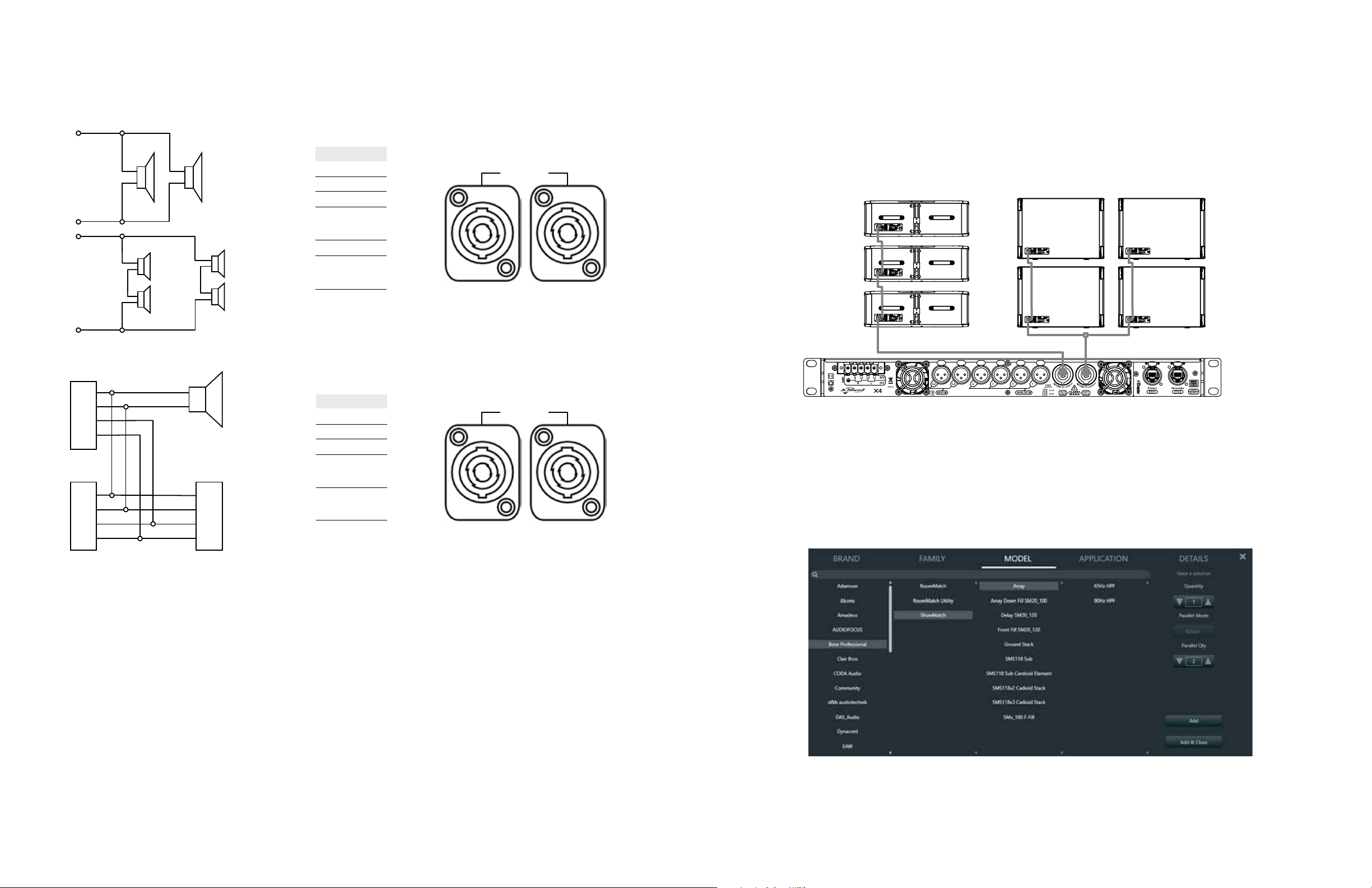
Recommended Amplification for Installed Applications
Bose Professional recommends the use of Bose PowerMatch PM8500 series amplifiers for applications where the
system will be permanently installed. Two configuration options are available:
Economy (-2.6 dB peak output in module LF)
This configuration is ideal for applications that do not require the full peak output of the LF section of the array to meet
customer SPL requirements. In this set up a single Voltage Bridged (VBr) channel is used to drive two LF sections and
a single Mono (M) channel is used to drive two HF sections within the array. A single Quad Bridge (QBr) channel is used
for each SMS118 subwoofer.
LF
NL4
HF
VBr
M
Performance
In this configuration, full peak power is delivered to the LF section of the array. This configuration is recommended for
live music performance venues.
In this configuration, a single Quad Bridge (QBr) channel is used to power two LF sections and a single Mono (M)
channel is used to power two HF sections of the array.
The SMS118 is powered by a single Quad Bridge channel.
LF
NL4
HF
QBr
LINK/ 1G
ACT
LINK/ 1G
M
LINK/ 1G
ACT
LINK/ 1G
QBr
LINK/ 1G
ACT
QBr
LINK/ 1G
10 11
PRO.BOSE.COMPRO.BOSE.COM
Page 8
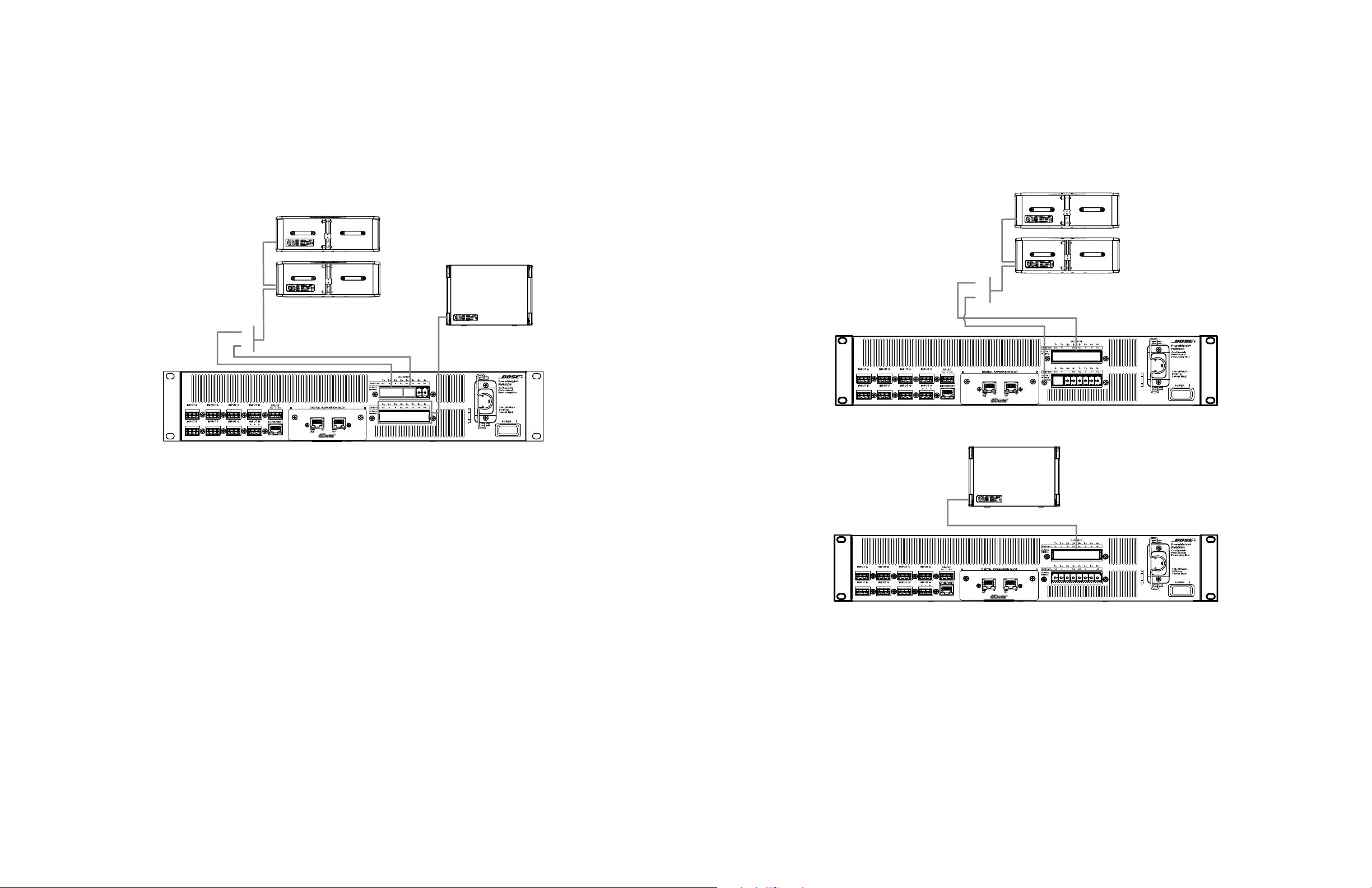
Recommended Signal Processing for Permanent Installations
The Bose PowerMatch PM8500N power amplifier (sold separately) is easily configured to provide the recommended
amplifier power for ShowMatch modules and arrays. The PM8500N also provides presets for all recommended signal
processing, including active crossover, EQ, alignment delay, protection limiting, array compensation EQ settings, and
cardioid subwoofer settings when used with the ShowMatch SMS118 subwoofer.
Presets may be selected from either the front panel of the PM8500N or through the ControlSpace Designer software.
From the front panel interface select Menu > DSP > Speaker Presets > ShowMatch to access the loudspeaker preset
library for ShowMatch systems.
Within ControlSpace Designer, while connected to the amplifier via either USB or Ethernet, loudspeaker presets are
applied within the loudspeaker processing block of the output processing section for the desired channel.
1) Open the SpeakerPEQ block for the channel where the preset EQ will be applied
2) Select Load Loudspeaker EQ
3) Navigate to the ShowMatch directory to access the ShowMatch system presets.
DESIGNING SHOWMATCH SYSTEMS
System Concept
ShowMatch systems feature next-generation array technology to deliver the scalability and flexibility needed to support
live music reproduction in a variety of venue shapes and sizes. Each ShowMatch array module includes two eight-inch
high-power neodymium woofers and four proprietary EMB2-S compression drivers capable of delivering array output
up to 145 dB SPL
Available in three vertical angles of 5, 10 and 20-degrees, each ShowMatch array module features changeable horizontal
waveguides that can be preconfigured to create both standard and DeltaQ line arrays.
DeltaQ line arrays provide consistent coverage and tonality across the coverage area by utilizing loudspeaker directivity,
Q, rather than electronic gain and module splay angles. This concept is particularly useful in installed applications where
the system designer’s intent is to fine tune the coverage of the array to the shape of the audience area. Optimizing
the coverage of the array further improves performance by reducing unwanted room reflections which cause an
inconsistent response and drive reverberation, reducing both speech and musical clarity.
ShowMatch array modules are oered in three vertical and four horizontal coverage patterns which can be configured
as shown in the following table:
SM5 Accessory Pre-installed Included with module NA
SM10 NA Included with module Pre-installed NA
SM20 NA Included with module Pre-installed Accessory
1
.
Available Horizontal Angles
55° 70° 100° 120°
ShowMatch systems utilize two preset components, a low frequency section, and a high frequency section. When
working with ControlSpace Designer or the front panel interface of the PowerMatch amplifier you will need to load the
preset for each section, (LF or HF), separately.
For additional information on system presets see Section 6.2, ShowMatch System Presets in this guide.
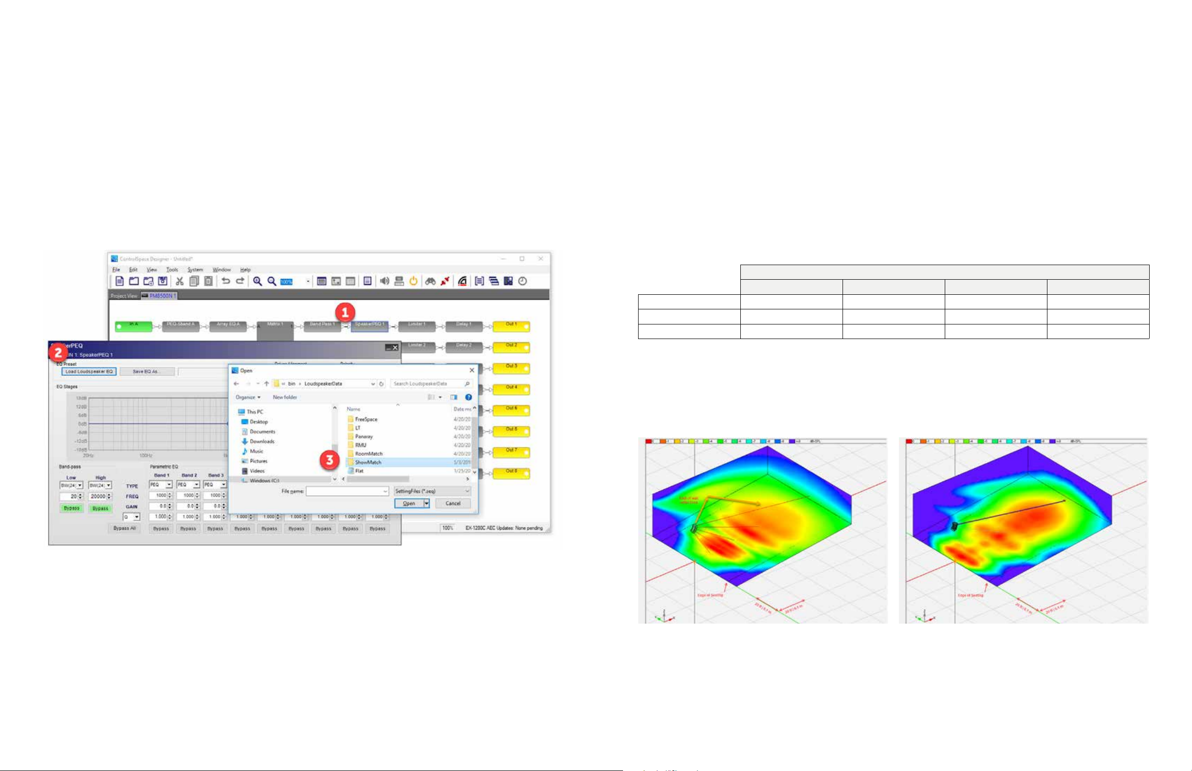
Using the various module configurations, it is possible to create a system design which focuses the energy on the
audience and minimizes the energy placed on side walls. The following illustration compares a ShowMatch DeltaQ line
array to a traditional line array comprised of modules which use the same vertical and horizontal angle.
Traditional Line Array with Fixed Horizontal Angles DeltaQ Array
Mid-band (1-4 kHz) coverage for traditional array with fixed
vertical and horizontal angles. To provide a consistent level across
the coverage area, the input to individual modules varies.
Mid-band (1-4 kHz) coverage for a ShowMatch DeltaQ array. In
this case the horizontal and vertical coverage vary across the
length of the array. A consistent level across the audience area
is achieved with acoustic gain rather than drive level from
the amplifier.
1
Calculated peak SPL for a 24 module array.
12 13
PRO.BOSE.COMPRO.BOSE.COM
Page 9
In rental and touring applications the DeltaQ concept oers the same consistency of coverage and response across the
coverage area, and in smaller, low-ceiling applications this concept can be used to deploy smaller arrays, which deliver
wide vertical coverage, as compared to arrays constructed of traditional line array modules.
A typical rental inventory includes all the fundamental components to build arrays of various sizes and output levels.
These components can be easily mixed and matched, transported, and configured for dierent applications.
Each array is comprised of three primary components:
Far Throw array sections are comprised of SM5 modules with a 70-degree horizontal coverage angle. The overall
size and throw distance required for the application will determine the quantity of modules configured in this way.
Mid Throw array sections constitute the main portion of the array and are comprised of SM5 modules with a
100-degree horizontal coverage angle.
Downfill Transition is the final section of the array and uses four modules to deliver 40 degrees of vertical coverage
to the nearest audience area. This is accomplished with two SM5 modules, one SM10 module, and one SM20
module, where all modules have a 100-degree horizontal coverage angle.
Far Throw 4x SM5 with 70° horizontal
Mid Throw 4x SM5 with 100° horizontal
Downfill 2x SM5, 1x SM10, 1x SM20, all
with 100° horizontal with 70° horizontal
SYSTEM SOFTWARE
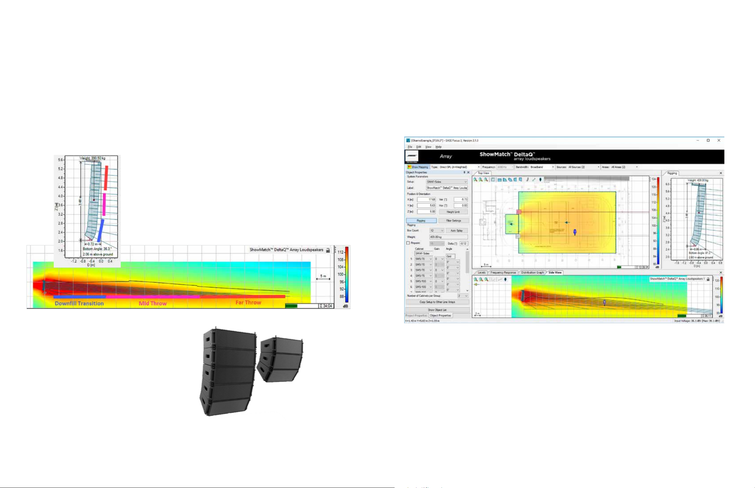
EASE Focus
EASE Focus 3 software allows 3D modeling of audience areas, predictions of acoustic direct-field coverage, sound
levels, and frequency response.
Once an array has been created, inter-box splay angles may be configured manually or using automated splay
calculation. SMS118 cardioid subwoofer presets are available within the software for the creation of cardioid
subwoofer arrays.
At the completion of the design a customizable report can be generated which contains the necessary details for
proper placement, aiming and configuration of array parameters.
The Bose ShowMatch GLL files are licensed to allow use in both Focus and “full” EASE software.
Typical ShowMatch array for outdoor concert supporting an audience of up to 5,000 people.
In low-ceiling applications, a DeltaQ array can be
deployed to deliver an array with a wide vertical
coverage angle using fewer modules than traditional
systems. In applications where the SPL level can be met
with this approach, a DeltaQ array oers the following
advantages:
Reduced array weight
Improved sight lines
Reduced set-up and installation time
1
For a detailed technical explanation of DeltaQ arrays see the AES paper “The influence of the directional radiation performance of the
individual speaker modules, and overall array, on the tonal balance, quality and consistency of sound reinforcement systems,”
presented at the 131st AES Convention in New York City, October, 2011.
14 15
50° vertical coverage
in both arrays
PRO.BOSE.COMPRO.BOSE.COM
Page 10

PowerSoft ArmoníaPlus
outdoor 1
PowerSoft ArmoníaPlus software provides ShowMatch system owners with the ability to set up and remotely control
and operate ShowMatch systems for rental applications and serves as the primary interface to the ShowMatch
Tour Rack.
Preset files are available with EQ, crossover, and limiter settings for all ShowMatch modules and subwoofers. In addition,
sample system configuration files are available for typical array configurations.
PowerSoft Armonía software is available for download at www.Armonía.powersoft.it/download-Armonía/
Outdoor Live Music Example 1
An outdoor live music application with an audience size of 5,000. In this application, two 12-module arrays are flown,
one to the left of the stage and one to the right with 16 SMS118 subwoofers arrayed in the front.
The expected SPL at the front-of-house position is 114 dBA with program material.
Preset downloads are available at PRO.BOSE.COM.
Main Arrays (x2)
10x SM5 Module
1x SM10 Module
1x SM20 Module
Front Fill
4x SM20 Module
LEFT RIGHT
SM5 70°
SM5 70°
SM5 70°
SM5 100°
SM5 100°
SM5 100°
SM5 100°
SM5 100°
SM5 100°
SM5 100°
SM10 100°
SM20 100°
SMS118
SMS118
SMS118
SMS118
SMS118
SMS118
Subwoofer
16x SMS118
Amplification
3x ShowMatch Tour Rack
FRONT FILLS
SM20 120° SM20 120°
SM10 120°
SUBS
SMS118
SMS118
SMS118
SMS118
SM10 120°
SMS118
SMS118
SMS118
SMS118
SM5 70°
SM5 70°
SM5 70°
SM5 100°
SM5 100°
SM5 100°
SM5 100°
SM5 100°
SM5 100°
SM5 100°
SM10 100°
SM20 100°
Preset Guide
Arrays Array 65 Hz HPF
Front Fills Front Fill SM20_120 150 Hz HPF
Subs SMS118 Sub 65 Hz LPF
SMS118
SMS118
16 17
PRO.BOSE.COMPRO.BOSE.COM
Page 11

outdoor 2
Outdoor Live Music Example 2
Indoor Live Music Application 1
In this example, a StageLine SL75 is used as the main stage for the production and two eight-module arrays are flown,
one to the left of the stage, one to the right. Ten ShowMatch SMS118 subwoofers are arrayed in the front of the stage.
The expected SPL at the front-of-house position is 112 dBA with program material.
Indoor Live Music Example 1
A 2,500-person-capacity live music venue with a general admission main floor and seated balcony area hosts live
music, comedy and special events throughout the year. In this example, the main arrays each use 14 ShowMatch
modules and a total of 18 showmatch subs are placed directly below the stage lip. The system is capable of providing
levels of 118 dBA at the front-of-house position.
Main Arrays (x2)
6x SM5 Module
1x SM10 Module
1x SM20 Module
Front Fill
3x SM20 Module
Subwoofer
10x SMS118
Amplification
3x ShowMatch Tour Rack
LEFT RIGHT
SM5 100°
SM5 100°
SM5 100°
SM5 100°
SM5 100°
SM5 100°
SM10 100°
SM20 100°
FRONT FILLS
SM20 120° SM20 120°
SM10 120°
SUBS
SMS118
SMS118
SMS118
SMS118
SMS118
SMS118
SMS118
SMS118
SMS118
SMS118
SM5 100°
SM5 100°
SM5 100°
SM5 100°
SM5 100°
SM5 100°
SM10 100°
SM20 100°
Preset Guide
Arrays Array 65 Hz HPF
Front Fills Front Fill SM20_120 150 Hz HPF
Subs SMS118 Sub 65 Hz LPF
Main Arrays (x2)
12x SM5 Module
1x SM10 Module
1x SM20 Module
SMS118
SMS118
SMS118
SMS118
Subwoofer
18x SMS118
Amplification
3x ShowMatch Tour Rack
LEFT RIGHT
SM5 70°
SM5 70°
SM5 100°
SM5 100°
SM5 100°
SM5 100°
SM5 100°
SM5 100°
SM5 100°
SM5 100°
SM5 100°
SM5 100°
SM10 100°
SM20 100°
SUBS
SMS118
SMS118
SMS118
SMS118
SMS118
SMS118
SMS118
SMS118
SM5 70°
SM5 70°
SM5 100°
SM5 100°
SM5 100°
SM5 100°
SM5 100°
SM5 100°
SM5 100°
SM5 100°
SM5 100°
SM5 100°
SM10 100°
SM20 100°
SMS118
SMS118
SMS118
SMS118
Preset Guide
Arrays Array 65 Hz HPF
Subs SMS118 Sub 65 Hz LPF
SMS118
SMS118
18 19
PRO.BOSE.COMPRO.BOSE.COM
Page 12

Indoor Live Music Example 2
small live music
Corporate AV application 1
This 700-person-capacity live music venue uses two four-module arrays to the left and right of the stage with four
SMS118 subwoofers ground stacked underneath the arrays.
The expected SPL is 110 dBA with program material.
Corporate AV Example 1
A corporate presentation within a hotel ballroom is the environment for this example. Arrays are flown at 14.5 feet,
(4.4 m) using the provided rigging pionts to the left and right of the presentation area to provide coverage for the
seated audience. In this example, each array consists of two SM5, one SM10 and one SM20 module and subs are not
used as the system is primarily for voice reinforcement.
Main Arrays (x2)
2x SM5 Module
1x SM10 Module
1x SM20 Module
Front Fill
2x SM20 Module
Subwoofer
4x SMS118
Amplification
1x ShowMatch Tour Rack
LEFT RIGHT
SM5 100°
SM5 100°
SM10 100°
SM20 100°
FILL
SM20 100° SM20 100°
SUBS
SMS118 SMS118 SMS118 SMS118
SM5 100°
SM5 100°
SM10 100°
SM20 100°
Preset Guide
Arrays Array 65 Hz HPF
Front Fills Front Fill SM20_120 150 Hz HPF
Subs SMS118 Sub 65 Hz LPF
Main Arrays (x2)
2x SM5 Module
1x SM10 Module
1x SM20 Module
Amplification
1x ShowMatch Tour Rack
LEFT RIGHT
SM5 100°
SM5 100°
SM10 100°
SM20 100°
SM5 100°
SM5 100°
SM10 100°
SM20 100°
Preset Guide
Arrays Array 65 Hz HPF
20 21
PRO.BOSE.COMPRO.BOSE.COM
Page 13

Corporate AV Example 2
Corporate AV application 2
SM5 100°
SM5 100°
SM5 100°
SM5 100°
SMS118
SMS118
SM5 100°
SM5 100°
SM5 100°
SM5 100°
SMS118
SMS118
LEFT RIGHT
A ground stack system is used to provide voice and music playback for a corporate function within a traditional hotel
ballroom. A ground-stack system provides voice and music playback for a corporate function within a traditional hotel
ballroom. The system has two ground stacks, one at the left of the stage, one at the right. Each contains four SM5
modules and two SMS118 subwoofers.
SHOWMATCH TOUR RACK
Product Description
ShowMatch loudspeaker systems are compatible with the ShowMatch Tour Rack, which is available in 120-volt and 230volt versions. The ShowMatch Tour Rack is a fundamental system building block and has been engineered to support a
variety of system configurations.
Each ShowMatch Tour Rack includes:
US rack European rack
ShowMatch Tour Rack Configuration
The ShowMatch Tour Rack ships ready to power a ShowMatch system with input routing and loudspeaker processing
preconfigured, allowing for “plug and play” operation for a system.
Power Distribution Unit
Three (3) PowerSoft X4D amplifiers
Cisco SG350-28 Managed Network Switch
AES Splitter & Signal Distribution Unit
Loudspeaker Distribution Unit
Ground Stack Arrays (x2)
4x SM5 Module
Subwoofer
2x SMS118
Amplification
1x ShowMatch Tour Rack
Preset Guide
Arrays Ground Stack 90 Hz HPF
Sub SMS118 Sub 90 Hz LPF
Input Priority and Routing
The system is preconfigured to auto-detect signal at the analog, AES and Dante® input points and will automatically
switch to the backup when input signal is lost. The PowerSoft X4D platform oers four input-signal-detection points:
Analog, AES, Dante Ch. 1-8, and Dante Ch. 9-16. Default input routing is configured for a basic system setup comprised
of Left, Right, Sub, and Fill input signals.
The following charts describe the input priority and routing that is preconfigured within the ShowMatch Tour Rack:
Input Priority Routing
Priority Input System Input Channel
1 Analog Left 1
2 AES Right 2
3 Dante Ch 1-8 Sub 3
4 Dante Ch 9-16 Fill 4
Mode: Auto Detection
Initial System Configuration
The initial system configuration is for a stereo system comprised of two six-module arrays with a total of 8 SMS118
subwoofers. A PowerSoft ArmoníaPlus project file is available for download at
www.Armonia.powersoft.it/download-Armonia/, which can be used to control the operation of the ShowMatch Tour
Rack. If the file is not available, connecting to the system will provide full operational control, however the devices
shown in the Design workflow will not be present.
NOTE: System outputs are muted in the initial configuration of the ShowMatch Tour Rack. Outputs can be unmuted
using the ArmoníaPlus software or by pressing the channel mute/unmute on the front panel of the PowerSoft X4D
amplifier. See the PowerSoft X4D Owner’s Manual for additional details.
22 23
PRO.BOSE.COMPRO.BOSE.COM
Page 14

1 Virtual Representation of ShowMatch
Ch 1+2
Ch 1 Ch 2 Ch 3 Ch 4
All Ch Ch 3+4
SM5 100°
SM5 100°
SM5 100°
SMS118
SMS118
SMS118
SMS118
SM5 100°
SM10 100°
SM10 100°
SM5 100°
SM5 100°
SM5 100°
SM5 100°
SM10 100°
SM10 100°
LEFT
Amp 2
RIGHT
SMS118
SMS118
SMS118
SMS118
Ch 1+2
Ch 1 Ch 2 Ch 3 Ch 4
All Ch Ch 3+4
Amp 1
Ch 1+2
Ch 1 Ch 2 Ch 3 Ch 4
All Ch Ch 3+4
Amp 3
1
2
Tour Rack.
2 Virtual Loudspeaker Group — each array
and sub section is grouped and includes an
advanced group control for Polarity, EQ, Delay
3
and Gain of this section.
3 Advanced Group Control for subs, arrays
and full system. Each contains Polarity, EQ,
Delay and Gain.
Initial System Loudspeaker Connections
Loudspeakers are connected via the Loudspeaker Connection Panel. The following diagram details the connections
between the ShowMatch Tour Rack, arrays and subs based on the pre-loaded configuration.
Loudspeaker connection panel
Input Connections
Input Panel
AES Inputs — Two AES pairs (1/2 and 3/4) are provided for connection of external AES devices. Each input pair is
transformer-isolated, electronically re-clocked and buered to the AES inputs of the amplifiers.
Two transformer-isolated outputs are provided for linking of AES signals to another device in the ShowMatch
Tour Rack.
Analog Inputs — Four analog inputs and four parallel link outputs are provided for connection of external analog
devices. The inputs are wired to the analog inputs of the amplifiers.
Dante Network (primary/secondary) — Neutrik EtherCON RJ45 connectors are wired using shielded cable to the
Cisco® Network switch where they are distributed to the amplifiers. Output connections are provided to link multiple
ShowMatch Tour Rack units.
Loudspeaker Connection Panel
Loudspeaker Connections
The Loudspeaker Connection Panel is divided into three identical sections, one for each amplifier.
Loudspeaker Outputs — Each amplifier output section is wired in parallel to provide flexibility in system configuration
wiring. Each output connection contains the following connections:
1 – NL8 – Carries all Output Channels
1 – NL4 – Carries Channels 1+2
1 – NL4 – Carries Channels 3+4
4 – NL4 – Each carries a single amplifier channel
The following describes the channel connector wiring and maximum channel loading:
Single Channel Connection Channel Pair Connection Quad Channel Connection
Connector Channel Pin Out Connector Channel Pin Out Channel Connector Pin Out
NL4 1 1±
NL4 2 1± 2± 2±
NL4 3 1±
NL4 4 1± 2± 4±
NL4 1
NL4
3
4
Max Loading per Connection Max Loading per Connection Max Loading per Connection
Qty Type Qty Type Qty Type
2 SMS118
1
3
ShowMatch Module
(bi-amped)
4 SMS118
1) Subs run in parallel, requires jumper
to second unit
1) Requires breakout cable
2) Subs run in parallel, requires jumper
to second unit
1±
1± 3±
2
3
1
NL8
4
6
1,2
8 SMS118
1) Requires breakout cable
2) Subs run in parallel, requires jumper
to second unit
ShowMatch Module
(bi-amped)
1±
1,2
24 25
PRO.BOSE.COMPRO.BOSE.COM
Page 15

SHOWMATCH TOUR RACK CONNECTION
Operation and configuration of the ShowMatch Tour Rack is accomplished using the ArmoníaPlus software, available for
download at www. PowerSoft-audio.com. When connecting to the ShowMatch Tour Rack use the following steps:
1. Make sure that the ShowMatch Tour Rack is powered on and an active Ethernet connection is established between
the PC and the rack.
2. Open the ArmoníaPlus software and open the Bose ShowMatch Rack configuration file. The ShowMatch rack ships
preconfigured for operation.
1
4. Amplifiers will be automatically detected and displayed on the right-hand side of the screen. If amplifiers are
not present, check your network settings.
Select the top-most amplifier within the virtual rack. It will be selected and display the number 1. Then select
the link/pair button on the front panel of the corresponding amp within the rack.
The two devices are now logically linked; a successful link is indicated when the paired devices are green.
3. You will need to associate the amplifier in the ShowMatch Tour Rack with the virtual devices in the configuration file.
To accomplish this first select “Match” from the workflow selections along the bottom edge of the screen.
1
Make sure that the PC is not running a fixed IP address. All devices in the ShowMatch Tour Rack are configured for DHCP operation
and will automatically default to an address in the range of (169.254.xxx.yyy) when no DHCP server is present. The PC will do the
same, allowing you to communicate with the amplifiers within the ShowMatch Tour Rack. For detailed connection and configuration
instructions for the PowerSoft X4 Dante amplifier see the PowerSoft X Series User Guide.
Repeat this process for remaining amplifiers. Once you have completed this for all amplifiers, the system is ready for
operation.
5. The ShowMatch Tour Rack is preconfigured to operate a system comprised of six ShowMatch modules per side with
four subwoofers per side.
The system is muted by default to prevent damage to system components during set up.
26 27
PRO.BOSE.COMPRO.BOSE.COM
Page 16

To unmute the system, select the Tune option within the workflow along the lower left of the screen. Then select Mute
All group control to unmute the system.
SHOWMATCH SYSTEM PRESETS
Presets are available for various configurations of ShowMatch systems and are found within both the ControlSpace
Designer software, used for PowerMatch amplifiers, and Armonía+ software for PowerSoft X4D amplifiers. The preset
libraries are identical, but, in some cases, small naming dierences are present.
ShowMatch Array Presets
All array presets have been optimized to provide a balanced response throughout the listening area. Preset choice is
based on the high pass selection for the array.
ShowMatch Array Presets – ShowMatch Constant Curvature Arrays
Preset name HF / LF Example Notes
For use with flown ShowMatch arrays.
Array
Array Downfill
SM20_120
65 Hz HPF
90 Hz HPF
65 Hz HPF
90 Hz HPF
Includes a Mid Frequency Coupling, (MFC) adjustment to
compensate for Mid Frequency Coupling based on array
length.
For use with SM20x120 module when used as downfill
module within in a ShowMatch array.
This requires that two (2) amp channels be devoted
to the SM20x120 since this EQ is dierent from other
modules within the array.
6. The system is now ready for operation.
Ground Stack
65 Hz HPF
90 Hz HPF
or
For use with ShowMatch modules in a ground stack
configuration.
Includes a Mid Frequency Coupling, (MFC) adjustment to
compensate for mid frequency coupling based on array
length.
28 29
PRO.BOSE.COMPRO.BOSE.COM
Page 17

ShowMatch Module Presets
ShowMatch module presets are optimized for specific applications and are named accordingly. Preset choice is based
on the high pass selection for the module.
Preset name HF / LF Example Notes
Front Fill
SMx_100
150 Hz HPF For use with SM5|10|20 when deployed as a front fill.
ShowMatch Cardioid Subwoofer Presets
The cardioid presets provided employ the gradient cardioid method to achieve the maximum amount of rejection
behind the array within the array’s passband. The standard and cardioid presets can be used as building blocks to
create a variety of array configurations and coverage patterns. The following are few of the most common applications.
2 Module Cardioid Ground Stack Side Stage Block Array Vertical Column Flown
Front Fill
SM20_120
150 Hz HPF For use with SM20x120 when deployed as a front fill
ShowMatch Subwoofer Presets
ShowMatch subwoofer presets are named according to their application and allow the creation of custom cardioid
configurations, or pre-configured cardiod arrays.
Preset name HF / LF Example Notes
SMS118
SMS118
Cardioid Element
SMS118 x2
Cardioid Stack
65 Hz LPF
90 Hz LPF
65 Hz LPF
90 Hz LPF
65 Hz LPF
90 Hz LPF
SMS118 – (2 per channel)
SMS118 used as cardioid cancellation unit within a
gradient cardioid subwoofer array.
Two SMS118 modules stacked in to deliver gradient
cardioid performance.
Requires two amplifier channels
FR – Front Firing SMS118
BA – Rear Firing SMS118
dB SPL
122
120
118
116
114
112
110
108
106
104
<103
Horizontal coverage (plan)
dB SPL
128
126
124
122
120
118
116
114
112
110
<109
Horizontal coverage (plan)
dB SPL
125
123
121
119
117
115
113
111
109
107
<106
Vertical coverage (elevation)
Three SMS118 modules stacked in to deliver gradient
SMS118 x
Cardioid Stack
30 31
65 Hz LPF
90 Hz LPF
cardioid performance.
Requires two amplifier channels
FR – Front Firing SMS118
BA – Rear Firing SMS118
Array Ground Stack
Sub
PRO.BOSE.COMPRO.BOSE.COM
Preset Guide
SMS118 x2
Cardioid Stack
Preset Guide
SMS118 (Front)
SMS118
Cardioid Element
(Back)
Preset Guide
SMS118 (Front)
SMS118
Cardioid Element
(Back)
Page 18

SHOWMATCH TRANSPORTATION ACCESSORIES
Transport Cart, 4xSM5 Modules
The 4xSM5 Array transport cart carries four ShowMatch
SM5 array modules locked together using their suspension
hardware with rear link bars pinned at zero degrees, (0°).
Designed to be easily broken down and stacked for storage, each cart is constructed
of aluminum to reduce weight while the top and bottom plates are constructed of
5/8-inch (15-mm) Baltic Birch plywood. A high-density polyurethane seat captures
the bottom module and prevents damage to the loudspeaker enclosure. Each cart
includes four locking casters.
Transport Cart, 2xSM5+10/20 Downfill
The 4xShowMatch Module downfill cart carries an SM20,
SM10 and two SM5 array modules preconfigured as the
downfill section of a larger ShowMatch Array.
Transport Case, 3xSM Modules
Bose Professional ShowMatch 3xSM5 transport cases
carry three ShowMatch SM5 modules that have been
locked together using their suspension hardware with
rear link bars pinned at zero degrees, (0°). The ATAstyle transport case is constructed of 1/2-inch (12-mm)
Baltic Birch plywood with a protective PVC laminate and
includes snap-back handles to assist with cover removal
and transportation, and four locking casters. The top
cover includes a recessed nameplate to accommodate
a 7x5-inch tour label.
Transport Case, 2xSM Modules
Bose Professional ShowMatch two-module transport
cases carry any combination of two ShowMatch
SM5/10/20 array modules. Internal EVA foam is custom
cut to module profiles, allowing them to sit securely within
the case during transport. The ATA-style transport case
is constructed of 5/8-inch (15-mm) Baltic Birch plywood
with a protective PVC laminate and includes snap-back
handles to assist with cover removal and transportation
and four casters. The top cover includes a recessed
nameplate to accommodate a 7x5-inch tour label.
ShowMatch Transport Case – 2x Frames and Pullbacks
Bose Professional ShowMatch Array Frame transport
cases carry either two ShowMatch full array frames
or two T-bar array frame, and two ShowMatch array
pullback brackets. The ATA-style transport case is
constructed of 1/2-inch (12mm) Baltic Birch plywood
with a protective PVC laminate and includes snap-back
handles to assist with cover removal and transportation,
and four non-locking casters. The top cover includes a
recessed nameplate to accommodate a 7x5-inch
tour label.
32 33
PRO.BOSE.COMPRO.BOSE.COM
Transport Dolly, 1-3 SMS118 Subs
Bose Professional ShowMatch SMS118 dolly carries either
one, two or three ShowMatch SMS118 subwoofers. SMS118
dollies contain integrated attachment points, allowing
the SMS118 to be pinned directly to the dolly; additional
subwoofers are pinned to each other. When not in use,
SMS118 dollies can be stacked for storage. The SMS118
dolly is constructed of powder-coated steel with high
density Polyurethane to reduce the risk of damage to
subwoofers.
Page 19

Truck Pack Information
Examples of truck pack configurations for various ShowMatch systems are shown below.
ShowMatch Truck Pack, North America
SHOWMATCH SUSPENSION HARDWARE
3.93 m
6Modules/
4Subsper side
BoxVan
1.91 m
2x
SMS1182xSMS118
2x
SMS1182xSMS118
2xSM
2xSM
4xSM
SM Rack
4xSM
16'BoxTruck 22'BoxTruck
91 in. 91 in.
2xSM
4xSM 4xSM
SM Rack
2x
SMS1182xSMS118
2x
SMS1182xSMS118
2x
SMS1182xSMS118
2x
SMS1182xSMS118
22'
2xSM
2xSM
SM Rack SM Rack SM Rack SM Rack
8Subsper side
SMS1182xSMS118
SMS1182xSMS118
2xSM
16'
4Subsper side
2x
2x
2xAF
6Modules/
97 in.
2xSM
2xSM
12Modules/
4xSM4xSM
2xAF4xSM4xSM
26'StraightTruck 43'Trailer
2x
SMS1182xSMS118
2x
SMS1182xSMS118
2x
SMS1182xSMS118
2x
SMS1182xSMS118
2xSM
2xSM
2xSM
2xSM
SM Rack SM Rack
SM Rack SM Rack
2xAF
26'
2x
SMS1182xSMS118
2x
SMS1182xSMS118
2x
SMS1182xSMS118
2x
SMS1182xSMS118
2xSM
2xSM
2xSM 2xSM
4xSM4xSM
2xAF4xSM4xSM
42'
98.5 in.
2xSM
2xSM
2xSM
2xSM
4xSM4xSM
Array Frame
Use the ShowMatch Array Frame
(SMAF) to create overhead
suspended arrays that contain
4xSM4xSM
subwoofer modules, or to create
ground stack arrays that use any
T-Bar Array Frame
Use the ShowMatch T-Bar Array
Frame (SMAFT) to create overhead
suspended arrays that contain mid/
high modules only.
combination of subwoofer modules,
mid/high modules, or both.
4xSM4xSM
2xAF
Pullback Bracket
Connect the ShowMatch Array
Pullback Bracket (SMPULL) to the
bottom full-range array module
to provide third-point suspension
to building structure. This allows
more extreme downward angle of
arrays than possible from two-point,
gravity-hang suspension.
12Modules/
8Subsper side
ShowMatch Truck Pack, Europe
Multipoint Bracket
The ShowMatch Array Frame
7.5TonneBox
2.35 m
2xSM
4xSM 4xSM
SM Rack
2x
SMS1182xSMS118
2x
SMS1182xSMS118
2xSM
2xAF
6.1 m
2xAF
6Modules/
4Subsper side
18TonneBox 30FootTrailer
2.44 m
2x
8 m
SMS1182xSMS118
2x
SMS1182xSMS118
2x
SMS1182xSMS118
2x
SMS1182xSMS118
2xSM
2xSM
2xSM 2xSM
SM Rack SM Rack
4xSM4xSM
2xAF4xSM4xSM
9 m
SMS1182xSMS118
SMS1182xSMS118
SMS1182xSMS118
SMS1182xSMS118
2xSM
2xSM
2xSM
2xSM
SM Rack SM Rack
SM Rack SM Rack
2x
2x
2x
2x
2xAF
2.41 m
2xSM
2xSM
2xSM
2xSM
Multipoint Bracket (SMAFMP)
expands the number of rigging
points along the center rail of the
Array Frame (SMAF) or T-Bar
Array Frame (SMAFT) from 7 to 45
4xSM4xSM
12Modules/
8Subsper side
w/ 8 module out-fill
& front fill
4xSM4xSM
4xSM4xSM
2xAF
possible points.
Ground Stack Bracket
Use the ShowMatch Ground Stack
Bracket (SMGSB) to build ground
stack arrays that contain ShowMatch
DeltaQ full-range loudspeaker
modules (SM5, SM10, and SM20),
subwoofer modules (SMS118), or a
combination of both.
12Modules/
8Subsper side
12Modules/
8Subsper side
w/ 8 module out-fill
& front fill
34 35
PRO.BOSE.COMPRO.BOSE.COM
Page 20

ShowMatch Array Frame (SMAF)
Product Weight: 83.0 lbs (37.6 kg).
Product weight includes one shackle adapter. Each shackle adapter is 1.5 lbs (0.7 kg).
ShowMatch T-Bar Array Frame (SMAFT)
Product Weight: 40.5 lbs (18.4 kg).
Product weight includes one shackle adapter. Each shackle adapter is 1.5 lbs (0.7 kg).
Single Point, 10:1 Working Load Limit (in accordance with ANSI E1.8-2012).
ShowMatch Array Frame (SMAF)
Center Rail
WLL = 1800 lbs (815 kg)
ShowMatch Array Frame (SMAF)
Side Rail
WLL = 1400 lbs (630 kg)
Single Point, 10:1 Working Load Limit (in accordance with ANSI E1.8-2012).
ShowMatch T-Bar Array Frame (SMAFT)
Center Rail
WLL = 1400 lbs (630 kg)
36 37
PRO.BOSE.COMPRO.BOSE.COM
Page 21

ShowMatch Array Pullback Bracket (SMPULL)
Product Weight: 15 lbs (18.4 kg).
ARRAY SUSPENSION
ShowMatch DeltaQ array loudspeakers are shipped with integrated link-bar suspension hardware. The suspension
system is designed to allow fast set up of typical concert-touring or fixed-installation arrays of up to 24 full-range or
18 subwoofer modules while maintaining a 10:1 safety factor when used with Bose ShowMatch Array Frame suspension
accessories.
Note: Always confirm safe working load limits with exact array configurations, pitch angles, and connection points
using either Bose Modeler or Bose Array Tool software.
Note: Bose ShowMatch loudspeakers and suspension accessories are intended for installation by professional
installers only!
Note: All lifting operations require two individuals positioned on each side of the loudspeaker.
Refer to PRO.BOSE.COM for additional product installation and setup information.
G
F
SE CONSULT BOSE SHOWMATCH MANUAL FOR DETAILED
E
PLEA
NG INFORMATION.
D
GGI
RI
C
B
SPENSION POINT
A
SU
G PER
CK POINTS FOR SHACKLE ADAPTER OR OPTIONAL ACCESSORY
WLL:1800 LBS/815 K
CENTER RAIL PI
20 21
19
17 18
WLL:1400 LBS/630 KG PER SUSPENSION POINT
10 11 12 13 14 1516
1 2 3 4 5 6 7 8 9
SIDE RAIL PICK POINTS
Single Point, 10:1 Working Load Limit (in accordance with ANSI E1.8-2012).
ShowMatch Array Pullback Bracket
(SMPULL) Center Suspension Point
WLL = 700 lbs (315 kg)
ShowMatch Array Pullback Bracket
(SMPULL) Side Suspension Point
WLL = 600 lbs (270 kg)
Fig. 1. Raise links on module.
Fig. 2. Insert pins to attach module to frame.
Connect Array Frame or T-bar Array Frame to Full-range Module
The ShowMatch Array Frame (SMAF) contains four connection points for subwoofer modules (all four corners), and
three connection points for full-range modules (two front corners and a center location). Each side rail provides 21
suspension points, labeled according to the image printed on the frame. The center rail provides seven suspension
points and is expandable to up to 45 points using the Multipoint Bracket Accessory (SMAFMP). For more information
about the Multipoint Bracket Accessory, see PRO.BOSE.COM.
The ShowMatch T-Bar Array Frame (SMAFT) contains three suspension points for full-range array modules (two front
corners and rear center). The center rail provides seven suspension points and is expandable to up to 45 points using
the Multipoint Bracket Accessory. The T-Bar Array Frame is compatible with full-range modules (SM5, SM10, and SM20)
only. Do not use the T-Bar Array Frame with subwoofer modules (SMS118). To create an array with subwoofer modules,
use the ShowMatch Array Frame.
The Array Frame and the T-Bar Array Frame each include two (2) shackle adapters to attach the frame to chains or
standard shackles, and four (4) quick pins to connect an array module to the frame. To create a narrower array, remove
the side end caps and tethered quick pins that are factory-installed on each loudspeaker module, and use the optional
Short Quick Pin Accessory Kit (SMQPS). For more information about the Short Quick Pin Accessory Kit, see
PRO.BOSE.COM.
To connect a ShowMatch Array Frame or T-Bar Array Frame to a full-range loudspeaker module:
1. Use Bose Modeler software or the Bose Array Tool to determine appropriate suspension points on array frames for
required aiming angles and to confirm that array does not exceed load limits of frame. For more information
on Modeler and the Bose Array Tool, see PRO.BOSE.COM.
2. Place array frame directly under chain motors.
3. Attach included frame shackle adapters to array frame at suspension points determined by software.
4. Lower chain motors and attach chains to shackle adapters installed on array frame.
5. Raise array frame to a height slightly greater than that of the first (top) module to be installed.
6. With one person per side, place first module directly under suspended array frame.
7. Raise the links on module: Remove the pins, slide the link switch from the STOW position to the LINK position,
and replace the pins. See Fig. 1.
38 39
PRO.BOSE.COMPRO.BOSE.COM
Page 22

8. Lower array frame onto first module.
9. Adjust module position to align pin holes of module and frame.
10. Insert two front pins (one on each side), then insert rear center pin to secure module to frame. See Fig. 2.
11. Raise array frame to a height slightly greater than that of the next module.
12. With one person per side, place next module directly under suspended array.
13. Lower array onto next module.
14. Align pin holes of second (bottom) module to pin holes of first (top) module.
15. Insert two front pins (one on each side), then insert rear center pin to secure .
16. Repeat steps to install additional modules in the array. Do not exceed load limits of frame.
Connect field wiring, test loudspeaker operation, and then elevate array assembly to final operating position.
G
F
N.
E
ORMATIO
PLEASE CONSULT BOSE SHOWMATCH MANUAL FOR DETAILED
D
RIGGING INF
C
NT
B
DAPTER OR OPTIONAL ACCESSORY
A
CK POINTS FOR SHACKLE A
I
WLL:1800 LBS/815 KG PER SUSPENSION POI
CENTER RAIL P
21
WLL:1400 LBS/630 KG PER SUSPENSION POINT
10 11 12 13 14 1516 17 18 19 20
1 2 3 4 5 6 7 8 9
SIDE RAIL PICK POINTS
Fig. 3. Raise links on subwoofer.
Fig. 4. Insert pins to attach subwoofer to frame.
Connect Array Frame to Subwoofer
The ShowMatch Array Frame (SMAF) provides four connection points for SMS118 subwoofers (one in each corner) and
21 suspension points on each side rail, labeled according to the image printed on the frame. The center rail provides
seven suspension points and is expandable to up to 45 points using the Multipoint Bracket Accessory (SMAFMP).
Note: Subwoofers are compatible with the ShowMatch Array Frame only. Do not use a T-Bar Array Frame with
subwoofer modules.
When flying an array that contains both full-range and subwoofer modules, the subwoofer modules must be in the top
positions of the array.
To connect a ShowMatch Array Frame to a subwoofer:
1. Use Bose Modeler software or the Bose Array Tool to determine appropriate suspension points on array frames for
required aiming angles and to confirm that array does not exceed load limits of frame. For more information on
Modeler and the Bose Array Tool, seePRO.BOSE.COM.
2. Place array frame directly under chain motors.
3. Attach included shackle adapters to array frame at suspension points determined by software.
4. Lower chain motors and attach chains to shackle adapters installed on array frame.
5. Raise array frame to a height slightly greater than that of the subwoofer.
6. With one person per side, place subwoofer directly under suspended array frame.
7. Raise each of the four corner links on the subwoofer by removing the pin, sliding the link switch from the STOW
position to the LINK position, and replacing the pin. See Fig. 3.
8. Lower array frame onto subwoofer.
9. Adjust subwoofer position to align pin holes of module and frame.
10. Insert two front pins (one on each side), then insert two rear pins (one on each side) to secure subwoofer to frame.
See Fig. 4.
11. Raise array frame to a height slightly greater than that of the next module.
12. With one person per side, place next module directly under suspended array.
13. Lower array onto next module.
14. Align links of second (bottom) module to links of first (top) module.
15. Insert two front pins (one on each side), then insert rear center pin to secure bottom module.
16. Repeat steps to install additional modules in the array. Do not exceed load limits of frame.
17. Connect field wiring, test loudspeaker operation, and then elevate array assembly to final operating position.
Fig 5. Pullback bar positioned with connection tabs facing up. Fig 6. Insert pins to attach pull back bracket to module.
Connect Pull Back Bracket to Full-range Module
Attach the ShowMatch Pull Back Bracket (SMPULL) to the bottom full-range array module to provide a third structural
attachment point when creating an array with a more extreme downard tilt.
The pull back bracket provides three suspension points along the rear to connect a pullback cable or the Transition
Bracket Accessory (SMSTK). For more information about the Transition Bar Accessory, see PRO.BOSE.COM.
When connecting a pullback cable, it is recommended to use either the center suspension point, both side suspension
points, or all three suspension points. The primary suspension points of the array frame should be as close as possible
to the center of gravity of the array to minimize the tension load in the pullback cable.
Use Bose Modeler software or the Bose Array Tool to determine if the pull back bracket is required and to confirm that
the pullback angle and working load is within acceptable safe limits. For more information on Modeler and the Bose
Array Tool, see PRO.BOSE.COM.
Note: The Pull Back Bracket is not intended to provide primary structural support for the entire array!
To connect the pull back bracket to a full-range array module:
1. Assemble the array on the Array Frame or T-Bar Array Frame by following the instructions in this manual and on
PRO.BOSE.COM.
2. Position the pull back bracket with the connection tabs facing up (toward the array). See Fig. 5.
3. Align the three connection tabs on the pull back bracket with the three connection points on the bottom full-range
array module (two in front, one in the rear center).
4. Insert two front pins (one on each side), then insert one rear pin to secure pull back bracket to module. See Fig. 6.
5. Attach pullback cable(s) to the bracket using the included shackles.
26. Connect field wiring, test loudspeaker operation, and then elevate assembly to final operating position.
7. Adjust length of pullback cable attached to the pullback bracket as required for desired array tilt angle.
40 41
PRO.BOSE.COMPRO.BOSE.COM
Page 23

Pickup Point
DX3
CAUTION: Always evaluate the safety and stability of the array to ensure it is within acceptable limits
before building. For support with evaluating array safety, contact your local Bose Sales Engineer.
Fig. 1. Pickup point DX3.
X1 X2 X3 X4 X5
Fig. 3. Multipoint bracket orientation X.
Fig. 5. Rigging point X3.
Fig. 2. Center rail rigging point D.
X1 X2 X3 X4 X5
Fig. 4. Center rail rigging point D and orientation X.
The shackles provided with the ShowMatch Array
Frame and T-Bar Array Frame should not be used
for suspension with the multi-point adapter.
Center Rail Suspension Using the Array Frame Multipoint Bracket
The ShowMatch Array Frame Multipoint Bracket (SMAFMP) expands the number of rigging points along the center rail
of the Array Frame (SMAF) or T-Bar Array Frame (SMAFT) from 7 to 45 possible points. Use Bose Modeler software or
the Bose Array Tool to determine the correct position and orientation of the multipoint bracket on the array frame to
achieve the required aiming angles and to confirm the array does not exceed load limits of the frame.
The first letter in the pickup point (A through F) indicates a rigging point on the center rail of the array frame; see Fig.
2. The second letter in the pickup point (X or Y) indicates the correct orientation of the multipoint bracket on the center
rail. When oriented correctly, the arrow printed on the multipoint bracket points to the front of the array; see Fig. 3.
Place the multipoint bracket on the center rail in the orientation indicated by the design software. Align the front hole
of the bracket with the rigging point specified in Step 3, and secure using the included bolts and bolt pins.
Example for a required pickup point of DX3.
1. DX3 is the specified pickup point to achieve the required array angle; see Fig. 1.
2. Locate center rail position D; see Fig. 2.
3. Orient the multipoint adapter for the X orientation; see Fig. 3.
4. Install the front mounting point of the multipoint adapter in position D using provided bolts, nuts and bolt pins;
see Fig. 4.
5. Use a graded 5/8” anchor shackle in position X3 of the multipoint adaptor to suspend the array; see Fig. 5.
GROUND STACK ARRAYS INSTALLATION
Use the ShowMatch Ground Stack Bracket (SMGSB) to build ground stack arrays that contain ShowMatch DeltaQ fullrange loudspeaker modules (SM5, SM10, and SM20), subwoofer modules (SMS118), or a combination of both.
The ground stack can include up to eight full-range modules. When using subwoofer modules, one subwoofer module
replaces two full-range modules. For example, the ground stack can include a maximum of 1 subwoofer and six fullrange modules, or two subwoofers and four full-range modules, etc.
If the ground stack contains one or more subwoofer modules, the subwoofers must be placed on the bottom of the
stack. You can place the bottom subwoofer module directly on the ground, or attach the subwoofer module to a
ShowMatch Array Frame (SMAF) and place the frame on the ground. If you use an array frame as the stack base, it is
recommended to attach the included leveling feet to the bottom of the frame.
If the ground stack contains one or more subwoofers and one or more full-range modules, you must use the ground
stack bracket to attach the full-range modules. You can attach the ground stack bracket directly to the top subwoofer,
or attach a ShowMatch Array Frame (SMAF) to the top subwoofer, and then attach the bracket to the frame.
If the ground stack contains full-range modules only, use the ShowMatch Array Frame (SMAF) as the base and attach
the ground stack bracket to the frame.
Product dimensions
Adjust Ground Stack Bracket Angle
Adjust the Ground Stack Bracket before installation of the first full-range module to control the pitch angle of the array.
The range of pitch angles depends on the first full-range module in the stack.
To adjust the Ground Stack Bracket angle, follow these instructions:
6. Remove the quick pin from the Ground Stack Bracket.
7. Position the top of the adjustable link directly under the line that corresponds to the desired position. The
indicator arrow on the adjustable link points to the position number; see Fig. 1. Refer to the table in Fig. 2 for the
corresponding pitch angle for each full-range module.
8. Replace the quick pin to lock the adjustable link in place.
Note: A negative angle measurement indicates that the module is aimed down. A positive angle measurement indicates
that the module is aimed up; see Fig. 3.
42 43
PRO.BOSE.COMPRO.BOSE.COM
Page 24

ShowMatch
WLL:1400 LBS/630 KG PER
SUSPENSION POINT
SIDE RAIL PICK POINTS
1 2 3 4 5
6 7 8 9
10 11 12 13 14 1516
17 18
19
20 21
PLEASE CONSULT BOSE SHOWMATCH MANUAL FOR DETAILED
RIGGING INFORMATION.
CENTER RAIL PICK POINTS FOR SHACKLE ADAPTER OR OPTIONAL ACCESSORY
WLL:1800 LBS/815 KG PER SUSPENSION POINT
A
B
C
D
E
F
G
1
2
3
4
5
6
7
8
9
7
8
9
BRACKET ANGLE
LOCATION
TM
Ground Stack Bracket
5
6
SMGSB
1
2
3
4
Position SM5 SM10 SM20
1 -22.5° -20° -15°
2 -20° -17.5° -12.5°
3 -17.5° -15° -10°
1
2
3
4
5
6
7
8
9
4 -15° -12.5° -7.5°
5 -12.5° -10° -5°
6 -10° -7.5° -2.5°
7 -7.5° -5° 0°
8 -5° -2.5° 2.5°
9 -2.5° 0° 5°
10 -0° 2.5° 7.5°
Fig. 1. Position number.
Fig. 2. Pitch angle by position and module.
Fig. 3. Negative and positive angle measurements.
Attach Ground Stack Bracket to ShowMatch SMS118
To attach the Ground Stack Bracket directly to the ShowMatch SMS118 subwoofer, follow these instructions:
9. Remove the four screws that attach the frame bracket to the base of the ground stack bracket; see Fig. 4.
10. Separate the ground stack bracket from the frame bracket. The base of the ground stack bracket should now
be flat.
11. Remove the four screws connecting the pole mount to the top of the subwoofer. Do not remove the actual pole
mount; see Fig. 5.
12. Attach the ground stack bracket to the subwoofer using the screws removed from the pole mount.
Fig. 4. Remove screws from bracket.
Fig 5. Remove pole mount screws.
Attach Ground Stack Bracket to ShowMatch Array Frame
To attach the Ground Stack Bracket to the ShowMatch Array Frame, follow these instructions:
1. Attach the leveling feet to the bottom of the frame; see Fig. 6. Fully tighten each screw to ensure the feet are level.
2. Align the Ground Stack Bracket with the holes along the center rail as indicated. The front ground stack hole should
be placed at Location D.
3. Attach the ground stack using the bolts and nuts from the array frame.
4. Use the included safety pins to ensure security of the bolts.
5. Connect the front two rigging locations of the first (bottom) Full-range module to the two front rigging locations
on the frame. Then connect the back of the module to the ground stack bracket.
Fig. 6. Ground Stack Bracket on array frame.
44 45
PRO.BOSE.COMPRO.BOSE.COM
Page 25

SHOWMATCH SYSTEM REFERENCE GUIDE
1+
1 -
2+
2-
1-
1+
1 -
2+
2-
1+
1 -
2+
2-
1+
1 -
2+
2-
1+
1-
2+
SM8
left
16 Ω 16 Ω
SM8 right
Grille-
mounted
NL4MP
Connector
System Testing
Periodic testing of the ShowMatch system components is required to assure that the system will deliver the desired
performance during operation. While the system is designed to provide a high level of reliability, it is recommended that
ShowMatch array modules and subwoofers be tested periodically to verify that all components are operational.
A recommended periodic check is to measure the DC resistance of the loudspeakers using a digital multimeter. This
test, when performed on individual modules, will provide an accurate reading of whether the devices are properly wired
and operating within their operating tolerances. Note that these measurements only validate
the electrical performance of the drivers and not the mechanical performance. For information
related to performing mechanical tests, e.g. rub and buzz, consult the ShowMatch DeltaQ Array
Loudspeakers service manual.
ShowMatch Loudspeakers Technical Specifications
(5)
(5)
Measurement Set Up
Test the ShowMatch module prior to operation and at room temperature using a digital
multimeter. To test the LF section place the probes across the 1 +/- pins; to test the HF place the
probes across the 2 +/- pins. Note that it may be necessary to make a breakout cable comprised
of an NL-4 to either banana or pig-tail with the connections labeled appropriately.
ShowMatch Full Range Modules (SM5, 10, 20)
LF Section (1 +/-)
Wiring Condition DC Resistance (Ohms) Tolerance
1+
SM8
left
SM8 right
16 Ω 16 Ω
Wiring Condition DC Resistance (Ohms) Tolerance
EMB2S
2-
EMB2S
EMB2S
12 Ω
12 Ω
}
}
EMB2S
Wiring Condition DC Resistance (Ohms) Tolerance
1+
1 2+
2-
All Drivers Functioning 5.1 0.5
1 x LF Driver Open 10.2 0.9
2 x LF Driver Open INF --
Any Driver Shorted 0 --
HF Section (2 +/-)
All Drivers Functioning 7.2
1 x HF Driver Open 14.4
2 x HF Driver Open INF or 14.4
3 x HF Driver Open INF
4 x HF Driver Open INF
Any Driver Shorted 0
ShowMatch SMS118 Subwoofers
SMS 118 LF Driver (1 +/-)
Functioning Woofer 3.3 0.4
Open INF -Short 0 --
NL4 to banana
breakout test cable
70 - 17,000 Hz 32 - 250 Hz
Common for all Full-range Modules SMS118
(1)
powder-coated finish, black
16-gauge (1.5 mm) perforated steel,
Omni with cardioid array configurations
Array (free field) Ground Stack
High
Frequency
optional 120°H)
Low
Frequency
High
21.2 x 30.1 x 30.5” / W: 29.8”
540 x 765 x 775 mm / W: 757 mm
(5)
(5)
W: 757 mm
303 x 793 x 461 mm /
11.9 x 31.2 x 18.1” / W: 29.8”
(5)
(5)
Frequency
W: 757 mm
Low
100°H x 10°V (or 70°H) 100°H x 20°V (or 70°H;
Frequency
70 Hz with minimum 12 dB / octave filter 30 Hz with minimum 12 dB / octave filter
450 W 100 W 750 W
Low Frequency High Frequency
SM5 SM10 SM20
High
Frequency
optional 55°H)
Low
70°H x 5°V (or 100°H;
94 dB 106 dB 94 dB 105 dB 94 dB 104 dB 94 dB 100 dB
121 dB 126 dB 121 dB 125 dB 121 dB 124 dB 123 dB 129 dB
282 x 793 x 465 mm /
11.1 x 31.2 x 18.3” / W: 29.8”
(5)
(5)
W: 757 mm
270 x 793 x 467 mm /
Frequency
(3)
(2)
1+
1 2+
2-
46 47
1+
1 2+
2-
Grillemounted
NL4MP
Connector
Single Module Performance
Frequency Response (+/- 3 dB)
PRO.BOSE.COMPRO.BOSE.COM
Transducers
Low Frequency 2 x Bose SM8 neodymium 8-inch woofers (3-inch voice coil) 1 x 18” neodymium woofer (4.5 inch voice coil)
Frequency Range (-10 dB) 60 - 17,000 Hz 29 - 300 Hz
High Frequency 4 x Bose EMB2S extended-HF neodymium compression driver (2-inch voice coil) None
Nominal Impedance 8 ohms + 6 ohms (LF/HF) 4 ohms
Recommended Crossover 800 Hz (acoustic; requires active 2-way crossover in DSP) 70 Hz for ShowMatch
Grille 16-gauge (1.5 mm) perforated steel, powder-coated finish, black
Finish Two-part spray polyurethane coating, black Two-part spray polyurethane coating, black
Power Handling,
Recommended High-Pass
Long-term Continuous
Power Handling, peak 1800 W 400 W 3000 W
Enclosure Material Baltic Birch plywood Baltic Birch plywood
Protection Filter
Enclosure
Environmental IPx4 IPx4
Connectors 2 x Neutrik NL4 wired parallel 2 x Neutrik NL4 wired parallel
Suspension / Mounting Integrated 3-point quick-pin rigging Integrated 4-point quick-pin rigging
Nominal Coverage Pattern
Sensitivity (SPL / 1 W @ 1 m)
Calculated Maximum SPL @ 1 m
Dimensions (H x W x D) - mm
Calculated Maximum SPL @ 1 m, peak 127 dB 132 dB 127 dB 131 dB 127 dB 130 dB 129 dB 135 dB
Dimensions (H x W x D) - inches 10.6 x 31.2 x 18.4” / W: 29.8”
Net Weight 30.6 kg (67.5 lbs) 29.7 kg (65.5 lbs) 29.0 kg (64.0 lbs) 61.9 kg (136.5 lbs)
Footnotes
(1) Frequency response and range measured on-axis in anechoic environment with recommended bandpass and EQ
(2) Bose extended-lifecycle test using pink noise filtered to meet IEC268-5, 6 dB crest factor, 500 hour duration
(3) Sensitivity measured in anechoic environment with recommended bandpass and EQ
(4) Maximum SPL calculated from sensitivity and power handling specifications, exclusive of power compression
(5) Width dimensions with side caps removed
Page 26

ShowMatch Systems Service and Repair Parts List
Contact Information
The service parts listed below are available for order from authorized Bose ShowMatch Master Resellers.
SKU QTY DESCRIPTION
ShowMatch Modules
751195-051S 1 1 ASSY, GRILLE, 5 DEG, SVCE
751195-101S 1 ASSY, GRILLE, 10 DEG, SVCE
751195-201S 1 ASSY, GRILLE, 20 DEG, SVCE
766712-2410 1 ASSY, HORN PANEL 55X05
762707-541S 2 ASSY, HORN PANEL, 70X5, SVCE
762707-551S 2 ASSY, HORN PANEL, 70X10, SVCE
762707-561S 2 ASSY, HORN PANEL, 70X20, SVCE
762706-841S 2 ASSY, HORN PANEL, 100X5, SVCE
762706-851S 2 ASSY, HORN PANEL, 100X10, SVCE
762706-861S 2 ASSY, HORN PANEL, 100X20, SVCE
766713-9610 1 ASSY, HORN PANEL, 120x20
756151-001S 2 WOOFER, 8 IN. 18 SOUND, SVCE
770438-011S 4 EMB2S COMPRESSION DRIVER
2 HANDLE, LIFTING
754285-001S 2 PIN, QUICK RELEASE, 12MM DIA, 38MM, SVCE
757313-001S 4 PIN, QUICK RELEASE, 8MM DIA.,16MM, SVCE
752363-011S 1 ASSY, INPUT/OUTPUT PANEL, 5 DEG, SVCE
752363-012S 1 ASSY, INPUT/OUTPUT PANEL, 10 DEG, SVCE
752363-013S 1 ASSY, INPUT/OUTPUT PANEL, 20 DEG, SVCE
768863-051S 2 ASSY, END CAP, 5 DEG
768863-101S 2 ASSY, END CAP, 10 DEG
768863-201S 2 ASSY, END CAP, 20 DEG
SMS118
298548 1 CONN, SPEAKON, 4 POS, MALE, 240V, 30A, BLK, SVCE
751086-011S 1 GASKET, CONNECTOR, NL4MP, SVCE
757729-011S 1 ASSY, GRILLE, SVCE
344052-001S 1 WOOFER, 18 INCH, B&C SPKRS, 18SW115, SVCE
367239-0110 8 SCREW, INSERT, RIGGING, BLK
740899-011S 4 FOOT, NESTING, SVCE
768875-012S 2 ASSY, END CAP, SVCE
757313-001S 8 PIN, QUICK RELEASE, 8MM DIA, 16MM LGTH, SVCE
748626-011S 1 ASSY, PANEL, I/O, SUB, SVCE
SKU QTY DESCRIPTION
Suspension Hardware
1 ARRAY FRAME SCHACKLE WITH BOLT AND CAPTURE
2 ARRAY FRAME RUBBER END-CAPS
2 XXX BOLT WITH CAPTURE PIN
1 ARRAY FRAME LOGO PLATE
8 SCREW, INSERT, RIGGING, BLK
4 FOOT, NESTING, SVCE
ShowMatch Amplifier Rack
1 10RU SHOWMATCH TOURING RACK - UNLOADED
1 INPUT SIGNAL DISTRIBUTION
1 SPEAKER SIGNAL DISTRIBUTION
1 CISCO SG350-28 LAYER 3 SWITCH
1 RACK POWER DISTRIBUTION UNIT - 120V
1 RACK POWER DISTRIBUTION UNIT - 240V
1 NETWORK CABLE SET
1 X4 AC SUPPLY CABLE SET
1 SIGNAL DISTRIBUTION CABLE SET
ShowMatch Transport Carts, Cases & Dollies
1 REPLACEMENT ALUMNIUM UPRIGHT
4 REPLACEMENT CASTER
For support with your ShowMatch system
wherever you are in the world, visit us at
BOSEPRO.link/contact.
48
PRO.BOSE.COM
Page 27

Page 28

© 2018 Bose Corporation. All rights reserved.
The Mountain, Framingham, MA 01701-9168 USA
PRO.BOSE.COM
All trademarks are the property of their respective owners.
01/2019
 Loading...