

Bose ShowMatch DeltaQ SMAF, ShowMatch DeltaQ SMAFT, ShowMatch DeltaQ SMPULL Installation And Safety Manuallines
Page 1
ShowMatchTM DeltaQTM Array Rigging Frames
Installation and Safety Guidelines
Page 2

Important Safety Instructions
pro.Bose.com
Please read this installation guide carefully and save it for future reference.
This product is intended for installation by professional installers only! This document is intended to provide professional installers with basic
installation and safety guidelines for this product in typical fixed-installation or portable-system applications. Please read this document and all safety
warnings before attempting installation.
WARNINGS:
• All Bose
• Unsafe mounting or overhead suspension of any heavy load can result in serious injury or death, and property damage. It is the
CAUTION:
• Installed loudspeaker arrays require regular inspection and routine maintenance to ensure proper function and
• Do not make unauthorized alterations to this product; doing so may compromise safety, regulatory compliance, system performance, and
NOTE: Always use Bose Modeler® or Bose Array Tool software to confirm safe working load limits with exact array configurations, pitch angles, and
connection points.
Guidelines for Installation and Setup of ShowMatch Array Module Loudspeakers
The installation information contained in this document is only a general guideline and cannot, as such, represent all requirements and precautions.
Accordingly, anyone using this material assumes all liability and is expressly responsible for the safety of all loudspeaker array designs and mounting
configurations applied in practice.
• Prior to the installation or portable-system setup of any overhead loudspeaker, a licensed professional engineer must approve the location and method
of attachment to the building structure or support-truss structure and confirm they are consistent with all building codes and regulations. Ensure the
mounting surface and the method of attaching the loudspeaker system to the surface is capable of supporting the total weight of the system. A safety
factor of 10:1 is recommended.
• Obtain all mounting system components from reputable manufacturers. Select a mounting system appropriate for your loudspeaker system and
its intended application. We recommend Bose mounting accessories when available. A licensed professional engineer must review the design and
fabrication of any custom mounting hardware.
• Do not suspend loudspeaker using handles as attachment points. Handles are NOT designed for load bearing!
• Use a safety cable, separately attached to the cabinet, at a point not in common with the load bearing attachment points of the mounting system to
the loudspeaker. This is recommended even if not required by local regulation. Consult a licensed professional engineer or a rigging professional for
proper design and installation.
• Do not under any circumstances climb the array.
®
products must be installed in accordance with local, state, federal and industry regulations. It is the installer’s responsibility to
ensure installation of the loudspeakers and mounting system is performed in accordance with all applicable codes, including local building
codes and regulations. Consult the local authority having jurisdiction before installing this product.
responsibility of the installer to evaluate the reliability of any mounting method used for their application. Only professional installers with
the knowledge of proper hardware and safe mounting techniques should attempt to install any loudspeaker overhead.
safe operation. Inspect mounting hardware and attachments for signs of corrosion, bending or any other condition that may decrease the
structural integrity. Immediately replace worn or damaged components.
may void the warranty.
2 - ShowMatchTM DeltaQTM Array Rigging Frames - Important Safety Instructions
Page 3
pro.Bose.com
Introduction
Product Applications
Bose® ShowMatchTM array frames and rigging accessories are designed for use with ShowMatch DeltaQTM
Array loudspeakers (SM5, SM10, and SM20) and ShowMatch DeltaQ Array subwoofers (SMS118).
Not for use with non-ShowMatch loudspeakers.
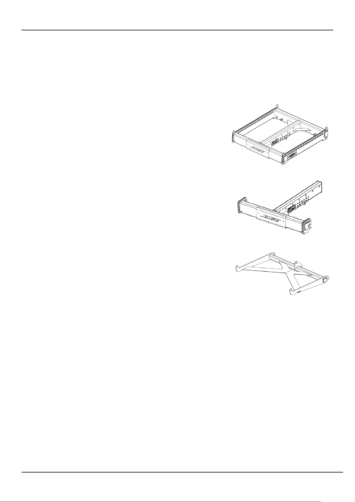
Array Frame
Use the ShowMatch Array Frame (SMAF) to create overhead
suspended arrays that contain subwoofer modules, or to create
ground stack arrays that use any combination of subwoofer
modules, mid/high modules, or both.
T-Bar Array Frame
Use the ShowMatch T-Bar Array Frame (SMAFT) to create overhead
suspended arrays that contain mid/high modules only.
Do not use the T-bar Array Frame with arrays that contain subwoofer
modules or to create ground stack arrays.
Array Pullback Bracket
Connect the ShowMatch Array Pullback Bracket (SMPULL) to the
bottom full-range array module to provide third-point suspension
to building structure. This allows more extreme downward angle of
arrays than possible from 2-point, gravity-hang suspension.
Additional Product Information
For more information and complete installation instructions for ShowMatch DeltaQ loudspeaker modules
and compatible accessories, refer to the installation guide available at pro.Bose.com. To request a printed
copy, use the phone numbers provided in the Contact Information section of this guide.
Manufacturer Declaration
We hereby declare that the ShowMatch DeltaQ Array loudspeakers and accessories have been designed
and built in compliance with BGV C1 standards and technical specifications. This declaration shall cease to
be valid if alterations are made to the equipment without our prior agreement.
Installation Guide - ShowMatchTM DeltaQTM Array Rigging Frames - 3
Page 4
Technical Information
Product Descriptions and Dimensions
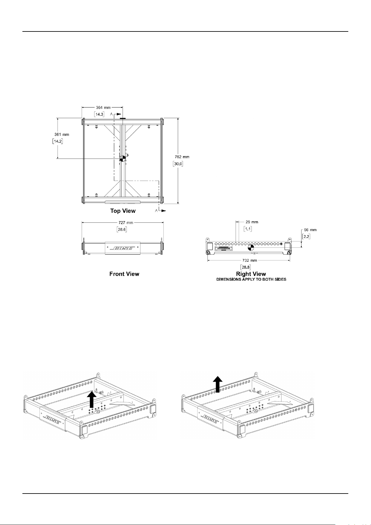
ShowMatchTM Array Frame (SMAF)
Product Weight: 83.0 lbs (37.6 kg)
Product weight includes one shackle adapter. Each shackle adapter is 1.5 lbs (0.7 kg).
pro.Bose.com
Single Point, 10:1 Working Load Limit (in accordance with ANSI E1.8-2012)
ShowMatch Array Frame (SMAF)
Center Rail
WLL = 1800 lbs (815 kg)
ShowMatch Array Frame (SMAF)
Side Rail
WLL = 1400 lbs (630 kg)
4 - ShowMatchTM DeltaQTM Array Rigging Frames - Installation Guide
Page 5

pro.Bose.com
Technical Information
ShowMatchTM T-Bar Array Frame (SMAFT)
Product Weight: 40.5 lbs (18.4 kg)
Product weight includes one shackle adapter. Each shackle adapter is 1.5 lbs (0.7 kg).
Single Point, 10:1 Working Load Limit (in accordance with ANSI E1.8-2012)
ShowMatch T-Bar Array Frame (SMAFT)
Center Rail
WLL = 1400 lbs (630 kg)
Installation Guide - ShowMatchTM DeltaQTM Array Rigging Frames - 5
Page 6

Technical Information
ShowMatchTM Array Pullback Bracket (SMPULL)
Product Weight: 15 lbs (18.4 kg)
pro.Bose.com
Single Point, 10:1 Working Load Limit (in accordance with ANSI E1.8-2012)
ShowMatch Array Pullback Bracket
(SMPULL) Center Suspension Point
WLL = 700lbs (315 kg)
ShowMatch Array Pullback Bracket
(SMPULL) Side Suspension Point
WLL = 600 lbs (270 kg)
6 - ShowMatchTM DeltaQTM Array Rigging Frames - Installation Guide
Page 7

pro.Bose.com
Installation
Array Rigging
ShowMatch DeltaQ array loudspeakers are shipped with integrated link-bar rigging hardware. The
rigging system is designed to allow fast setup of typical concert-touring or fixed-installation arrays of up
to 24 full-range or 18 subwoofer modules while maintaining a 10:1 Safety Factor when used with Bose®
ShowMatch Array Frame Rigging Accessories.
Note: Always confirm safe working load limits with exact array configurations, pitch angles, and
connection points using either Bose Modeler® or Bose Array Tool software.
Note: Bose ShowMatch loudspeakers and rigging accessories are intended for installation by professional
installers only!
Note: All lifting operations require two individuals positioned on each side of the loudspeaker.
Refer to pro.Bose.com for additional product installation and setup information.
Connect Array Frame or T-Bar Array Frame to Full-Range Module
The ShowMatch Array Frame (SMAF) contains four connection points for subwoofer modules (all four
corners), and three connection points for full-range modules (two front corners and a center location).
Each side rail provides 21 rigging points, labeled according to the image printed on the frame. The center
rail provides seven rigging points, and is expandable to up to 45 points using the Multipoint Bracket
Accessory (SMAFMP). For more information about the Multipoint Bracket Accessory, see pro.Bose.com.
The ShowMatch T-Bar Array Frame (SMAFT) contains three rigging points for full-range array modules
(two front corners and rear center). The center rail provides seven rigging points, and is expandable to
up to 45 points using the Multipoint Bracket Accessory. The T-Bar Array Frame is compatible with fullrange modules (SM5, SM10, and SM20) only. Do not use the T-Bar Array Frame with subwoofer modules
(SMS118). To create an array with subwoofer modules, use the ShowMatch Array Frame.
The Array Frame and the T-Bar Array Frame each include two (2) shackle adapters to attach the frame to
chains or standard shackles, and four (4) Quick Pins to connect an array module to the frame. To create
a narrower array, remove the side end caps and tethered quick pins that are factory-installed on each
loudspeaker module, and use the optional Short Quick Pin Accessory Kit (SMQPS). For more information
about the Short Quick Pin Accessory Kit, see pro.Bose.com.
Installation Guide - ShowMatchTM DeltaQTM Array Rigging Frames - 7
Page 8

Installation
pro.Bose.com
To connect a ShowMatch Array Frame or T-Bar Array Frame to a full-range loudspeaker module:
1. Use Bose® Modeler® software or the Bose Array Tool to determine appropriate rigging points on array
frames for required aiming angles, and to confirm that array does not exceed load limits of frame. For
more information on Modeler and the Bose Array Tool, see pro.Bose.com.
2. Place array frame directly under chain motors.
3. Attach included frame shackle adapters to array frame at rigging points determined by software.
4. Lower chain motors and attach chains to shackle adapters installed on array frame.
5. Raise array frame to a height slightly greater than that of the first (top) module to be installed.
6. With one person per side, place first module directly under suspended array frame.
7. Raise the links on module: Remove the pins, slide the link switch from the STOW position to the LINK
position, and replace the pins. See Fig. 1.
8. Lower array frame onto first module.
9. Adjust module position to align pin holes of module and frame.
10. Insert two front pins (one on each side), then insert rear center pin to secure module to frame. See Fig.
2.
11. Raise array frame to a height slightly greater than that of the next module.
12. With one person per side, place next module directly under suspended array.
13. Lower array onto next module.
14. Align pin holes of second (bottom) module to pin holes of first (top) module.
15. Insert two front pins (one on each side), then insert rear center pin to secure .
16. Repeat steps to install additional modules in the array. Do not exceed load limits of frame.
17. Connect field wiring, test loudspeaker operation, and then elevate array assembly to final operating
position.
Fig. 1. Raise links on module Fig. 2. Insert pins to attach module to frame
8 - ShowMatchTM DeltaQTM Array Rigging Frames - Installation Guide
Page 9

pro.Bose.com
Installation
Connect Array Frame to Subwoofer
The ShowMatchTM Array Frame (SMAF) provides four connection points for SMS118 subwoofers (one in
each corner) and 21 rigging points on each side rail, labeled according to the image printed on the frame.
The center rail provides 7 rigging points, and is expandable to up to 45 points using the Multipoint Bracket
Accessory (SMAFMP).
Note: Subwoofers are compatible with the ShowMatch Array Frame only. Do not use a T-Bar Array Frame
with subwoofer modules.
When flying an array that contains both full-range and subwoofer modules, the subwoofer modules must
be in the top positions of the array.
To connect a ShowMatch Array Frame to a subwoofer:
1. Use Bose® Modeler® software or the Bose Array Tool to determine appropriate rigging points on array
frames for required aiming angles, and to confirm that array does not exceed load limits of frame. For
more information on Modeler and the Bose Array Tool, see pro.Bose.com.
2. Place array frame directly under chain motors.
3. Attach included shackle adapters to array frame at rigging points determined by software.
4. Lower chain motors and attach chains to shackle adapters installed on array frame.
5. Raise array frame to a height slightly greater than that of the subwoofer.
6. With one person per side, place subwoofer directly under suspended array frame.
7. Raise each of the four corner links on the subwoofer by removing the pin, sliding the link switch from
the STOW position to the LINK position, and replacing the pin. See Fig. 3.
8. Lower array frame onto subwoofer.
9. Adjust subwoofer position to align pin holes of module and frame.
10. Insert two front pins (one on each side), then insert two rear pins (one on each side) to secure
subwoofer to frame. See Fig. 4.
11. Raise array frame to a height slightly greater than that of the next module.
12. With one person per side, place next module directly under suspended array.
13. Lower array onto next module.
14. Align links of second (bottom) module to links of first (top) module.
15. Insert two front pins (one on each side), then insert rear center pin to secure bottom module.
16. Repeat steps to install additional modules in the array. Do not exceed load limits of frame.
17. Connect field wiring, test loudspeaker operation, and then elevate array assembly to final operating
position.
Fig. 3. Raise links on subwoofer
Fig. 4. Insert pins to attach subwoofer to frame
Installation Guide - ShowMatchTM DeltaQTM Array Rigging Frames - 9
Page 10

Installation
pro.Bose.com
Connect Pull Back Bracket to Full-Range Module
Attach the ShowMatch Pull Back Bracket (SMPULL) to the bottom full-range array module to provide a
third structural attachment point when creating an array with a more extreme downard tilt.
The pull back bracket provides three rigging points along the rear to connect a pullback cable or the
Transition Bracket Accessory (SMSTK). For more information about the Transition Bar Accessory, see pro.
Bose.com.
When connecting a pullback cable, it is recommended to use either the center rigging point, both side
rigging points, or all three rigging points. The primary suspension points of the array frame should be as
close as possible to the center of gravity of the array to minimize the tension load in the pullback cable.
Use Bose Modeler software or the Bose Array Tool to determine if the pull back bracket is required and to
confirm that the pullback angle and working load is within acceptable safe limits. For more information on
Modeler and the Bose Array Tool, see pro.Bose.com.
Note: The Pull Back Bracket is not intended to provide primary structural support for the entire array!
To connect the pull back bracket to a full-range array module:
1. Assemble the array on the Array Frame or T-Bar Array Frame by following the instructions in this
manual and on pro.Bose.com.
2. Position the pull back bracket with the connection tabs facing up (toward the array). See Fig. 5.
3. Align the three connection tabs on the pull back bracket with the three connection points on the
bottom full-range array module (two in front, one in the rear center).
4. Insert two front pins (one on each side), then insert one rear pin to secure pull back bracket to module.
See Fig. 6.
5. Attach pullback cable(s) to the bracket using the included shackles.
6. Connect field wiring, test loudspeaker operation, and then elevate assembly to final operating position.
7. Adjust length of pullback cable attached to the pullback bracket as required for desired array tilt
angle.
Fig 5. Pullback bar positioned with connection tabs facing up Fig 6. Insert pins to attach pull back bracket to module
10 - ShowMatchTM DeltaQTM Array Rigging Frames - Installation Guide
Page 11

pro.Bose.com
Contact Information
Additional Information
Visit us on the web at pro.Bose.com.
Americas
(USA, Canada, Mexico, Central America, South America)
Bose Corporation
The Mountain
Framingham, MA 01701 USA
Corporate Center: 508-879-7330
Americas Professional Systems,
Technical Support: 800-994-2673
Australia
Bose Pty Limited
Unit 3/2 Holker Street
Newington NSW Australia
61 2 8737 9999
Belgium
Bose N.V. / S.A
Limesweg 2, 03700
Tongeren, Belgium
012-390800
China
Bose Electronics (Shanghai) Co Ltd
25F, L’Avenue
99 Xianxia Road
Shanghai, P.R.C. 200051 China
86 21 6010 3800
France
Bose S.A.S
12 rue de Temara
78100 St. Germain en Laye, France
01-30-61-63-63
Germany
Bose GmbH
Max-Planck Strasse 36D 61381
Friedrichsdorf, Deutschland
06172-7104-0
Hong Kong
Bose Limited
Suites 2101-2105, Tower One, Times Square
1 Matheson Street, Causeway Bay, Hong Kong
852 2123 9000
India
Bose Corporation India Private Limited
Salcon Aurum, 3rd Floor
Plot No. 4, Jasola District Centre
New Delhi – 110025, India
91 11 43080200
Italy
Bose SpA
Centro Leoni A – Via G. Spadolini
5 20122 Milano, Italy
39-02-36704500
Japan
Bose Kabushiki Kaisha
Sumitomo Fudosan Shibuya Garden Tower 5F
16-17, Nanpeidai-cho
Shibuya-Ku, Tokyo, 150-0036, Japan
TEL 81-3-5489-0955
www.bose.co.jp
The Netherlands
Bose BV
Nijverheidstraat 8 1135 GE
Edam, Nederland
0299-390139
United Kingdom
Bose Ltd
1 Ambley Green, Gillingham Business Park
KENT ME8 0NJ
Gillingham, England
0870-741-4500
See website for other countries
Importer Information
European Union
Bose GP, Castleblayney Road, Carrickmacross, County Monaghan, Ireland
China
Bose Electronics (Shanghai) Company Limited, Part C, Plan 9, No. 353 North Riying Road, China
(Shanghai) Pilot Free Trade Zone
Taiwan
Bose Taiwan Branch, 9F-A1, No. 10, Section 3, Minsheng East Road, Taipei City 104, Taiwan
Tel: 886 2 2514 7977
Mexico
Bose de México, S. de R.L. de C.V., Paseo de las Palmas 405-204, Lomas de Chapultepec, 11000 México,
D. F.
Tel: 001 800 900 2673
Limited Warranty
Your product is covered by a limited warranty, Visit pro.Bose.com for warranty details.
The warranty information provided with this product does not apply in Australian and New Zealand. See
our website at www.bose.com/au/warranty or www.bose.com/nz/warranty for details of the Australian
and New Zealand warranty.
Installation Guide - ShowMatchTM DeltaQTM Array Rigging Frames - 11
Page 12

©2016 Bose Corporation, The Mountain,
Framingham, MA 01701-9168 USA
AM772786 Rev. 00
 Loading...