

Page 1
The Bose"
Acoustimass® SE-5
/"Speaker
System
Owne r’ s Gui de
Page 2
Before You Begin ...
We would like lo thank you for purchasing ihe Bose'
AcouSimass - SE-5 speaker system. This product combines
iwo Bose technologies to create a versatile ^siem that wilt
allow you to experience the full realism and impact available
trom the most demanding sound sources. irKluding com
pact discs. Patented Acoustimass speaker technology otters
ihe benelits ol purer sound and virtual invisihility, while
Direct/Retlecting' speaker design allows you lo hear full
balanced stereo throughout your listening room. We are
confident that these advanced technologies and the quality
construction of the SE-5 system vrill provide you v/ilh many
years ol Irouble-lree listening pleasure.
The operating principles and wiring contiguration of the SE-5
system are signiiicanily difterent from those ol conventional
speakers. This not only allows the SE-5 system lo provide
you with great sound, but also oilers placement flexibility not
available from conventional speakers. For best results, and
easy installation, please take Ihe lime to read this own
er's guide
Please Note: The Acoustimass speaker technology used in
the SE-5 system signi(ic3nfiyK<S\ice$ audible distortion.
Because oi this, you may be less likely to notice the distinc
tive distorted sounds produced v/hen a speaker is driven
beyond its limits. Exercise caution when playing the SE-5
system at high volume levels.
Unpacking the SE-'S System
Alter opening Ihe carton, remove all packing material and
caretuliy lift out the components ol the SE-5 system. Save all
Ihe cartons and packing material in case the system needs
to be transported at a later time. If any of the components
appear damaged, do not attempt lo use the system
Instead, ropack the system in its original canon and notily
your authorized Bose dealer immediately.
Setting Up the System
Before you can install and adjust the ^stem's components,
lake a minute to famiiiariK yourselt with them, 'ibur system
should include:
2 Stereo largeiing^ arrays
1 Acoustimass' module (the larger black cabinet)
4 wires
The SE-5 system oilers many advantages not available Irom
a conventkir^al speaker system, among them, remarkable
freedom of placement. Acoustimass speaker technology
allows you lo place the Acoustimass module almost anyv/here. even under furniture. The compact Stereo Targeting
arrays can also be positioned in your listening mom wher
ever they create the best balance ol higher frequency sound.
Below are some guidelines lor setting up your system.
A. Seieci the locaiion wtiere you intend to place Ihe tell and
right Stereo Targeting arrays. Note lhal wires from
the arrays connect to the Acoustimass module, so you
should locate the Stereo Targeting arrays so lhal the
wires will reach the location you have chosen lor the
module.
Note: White Ihe wires provided are adequate lor most instal
lations, you may increase the distance between the Stereo
Targeting' arrays and the Acoustimass module by splicing
in additional wire, tl you do so, use similar gauge (16 or 18
gauge) or thicker vnre, and make sure you maintain the cor
rect phase (" -r- ’’ lo “ ’ and " to “ -"). and properly con
nect the wires.
Page 3
6. Position the Stereo Targeting - arrays vnth your audio
or video system to suit your musical taste and location
preferences. In average si¿ed listening rooms, the best
slereophortic effects result when the left and right Stereo
Targeting arrays are spaced 6 to 12 leet apart (appmxi-
maieiy 1.8-3.6 m). However, you can slill achieve excel'
kit results with separation as great as 15 feel
ppproximalely 4.5 m).
€
Note: For video applications, separation will vary to allov/
the Stereo Targeting • arrays lo be located on each side of a TV
or monitor. For more information on video applications, see
Part Dot this section.
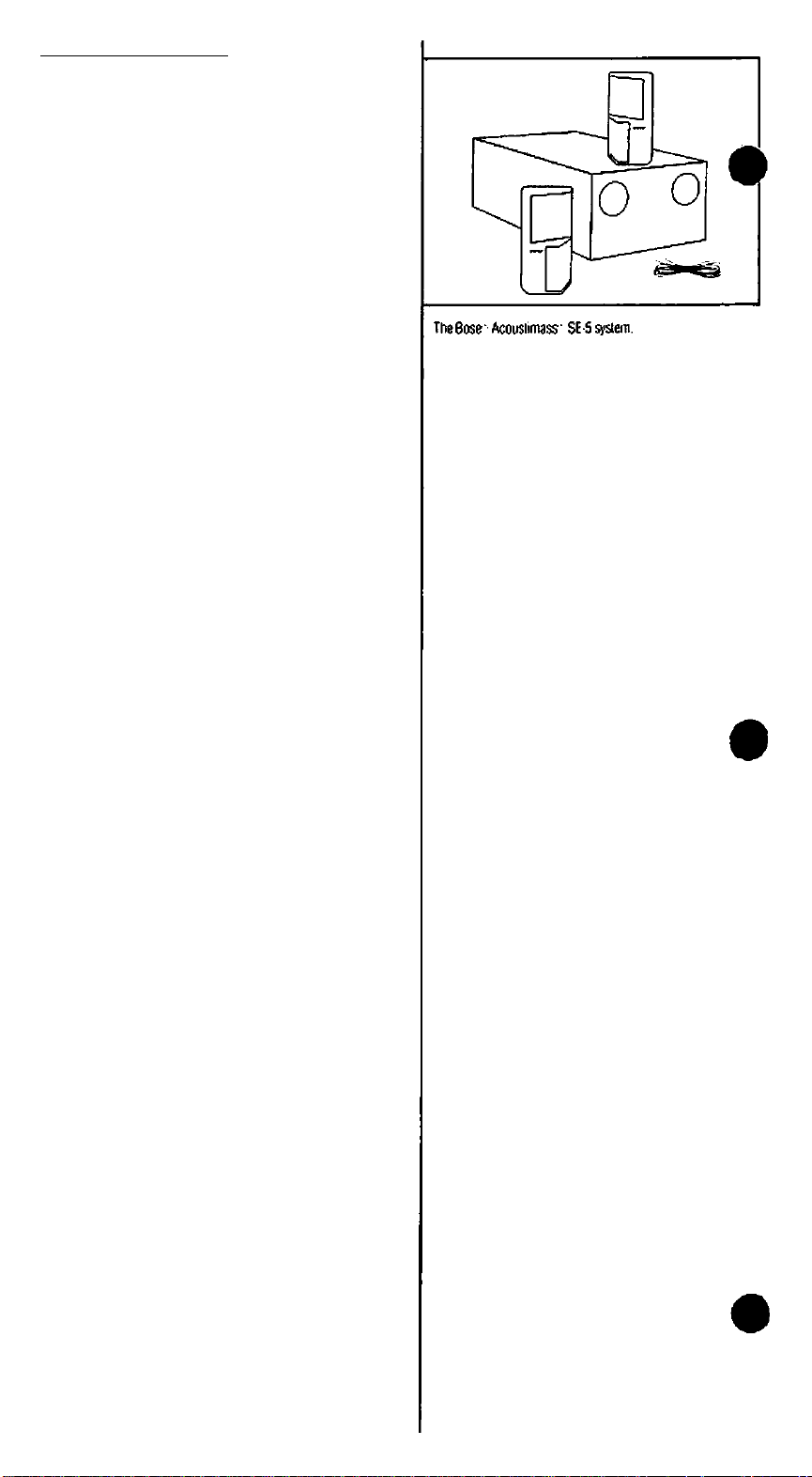
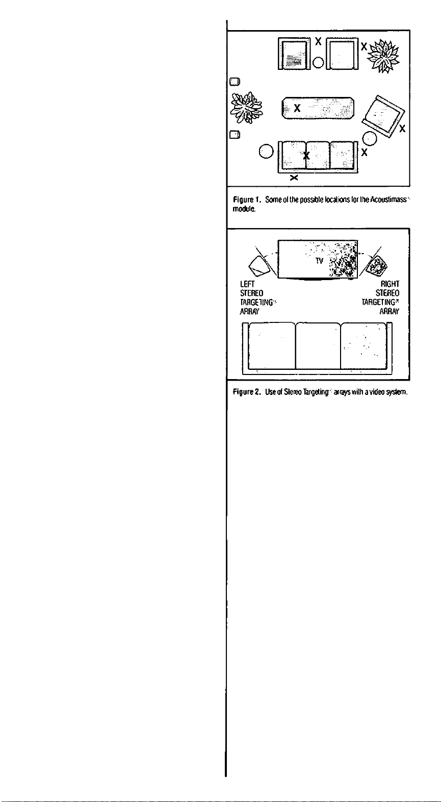
C. The Acou^imass' module can be located virtually any
where in your listening room (Figure 1)in either a vertical
or horizontal position. Its unique Acoustimass speaker
technology delivers room filling bassirom almost any
where. Feel tree to hide the Acoustimass module under a
bed or table, or even behind a sofa. JusI remember not to
block the two round openings in the end of the unit. \bu
should allow at least 2 inches (approximately 5 cm) of
open space between these openings and the v/all or
olher surface.
Unlike conveniional itoorsianding or bookshelf speakers,
you can line lune the bass response oi your SE-6 system
wilhoul compromising accurate stereo imaging. Just
change the location ol the Acoustimass module within
your listening room. For typical listening environments,
positioning the module along a v/all 3 lo 5 leet (appmximately 1 to 1.5 meters) Imm a corner provides a normal
balance of frequencies from your SE-5 system. Moving
the module closer lo the walls andfor corners ol your
room will increase bass response, while moving il lov/ard
the center of your mom will decrease it. In most rooms, it
should be reasonably easy to choose a location which is
convenient, yet provides fusing bass response.
|ie Stereo Targeting arrays ol your S€-5 system are mag
Iriicaiiy shielded for use with video systems. This allovrs
you to position the arrays close lo your TV or monitor
without adversely alfecling the picluie quality (as hap
pens with conveniional. nonshi^ded speakers). Refer
loFrgure2.
Note: The Acou^imass module itsell is nol magnetically
shielded and should be placed at least three leet away from
your monitor lo avoid inierlerence.
Connecting the SE-5 System
to Your Stereo
Caution: Before attempting to connect the SE-5
system, unplug your receiver or amplifier from the
wall outlet.
Note: While the SE-5 astern is rated at 6 ohms the
speaker’s impedance actually averages helween 6 and 9
ohms over most of its operating range.
A. Locale the wires which were packed with the system. Vbu
will lind four identical sets. Two sets connect the Stereo
Targeting arr^s lo the Acoustimass module, v/hile the
other two sets connect the Acoustimass module to your
receiver or amplilier.
B. Examine the ends of the wires. For each set. one wire
will have a red marker. For each connection you make,
always connect the wire with the red marker to the
"-I-'terminal.
¡Locale the terminals on the rear o< the left Stereo Target"itj array. Depress the red +") lab. insert the lead wiih
Ihc red mark^ (Figure 3). and release Ihe tab. The lead
Should be held snugly in place by the terminal. Repeat
the process for the black terminal and the other lead.
Page 4

0. Locale lhe lerminals marked “OUTPUTS TO STEREO
TARGETING ' ARRAYS' ûfi the rear of the Acousllmass
module (Figure 4). Connect the other end of wires from
the left Stereo Targeting array to the pair of terminals
marted “L*. Make sure that the lead v/rth the red marker
is connected to the “+and the other lead to the "
terminal.
E. Repeat steps C and Dior the right array.
F. Loc^e the left channel terminals on the Acoustimass '
module marked "INPUTS FROM AMP OR RECEIVER:'
Depress the red ("+tah, insert the lead with Ihe red
marker, and release the lab. Repeat the process for the
black terminal and the other lead.
G Locale the speaker outputs on your amplifier or recetver.
Connect Ihe other ends of the wire from the left channel
of the Acoustimass module to the terminals marked "L*
Figure 3. Property connecting wires (0 a terminal
or "LEFT." Make sure that the lead with the red marker is
connected to the '+" and the other lead is connected to
the "-"terminal.
H. Repeat steps F and G for the right channel.
1. Before you plug in your recerver or amplifier, make sure
lhal no strands of wire from any terminal are brushing
against any other terminal. Such “bridged” wires
create short circuits which can damage your re>
ceiveroramplifer
J. Plug in your receiver, turn on your system, and enjoy
your music!
Checking the System
Once you have begun listening to your SE-5 system, Ihe
following test will hdp you make sure that Ihe system is
working properly;
A. Turn the balance control on your receiver or amplifier
completety to the lelt. II you have connected the Stereo
Targeting • arrays properly, you vM hear music from the
left array, but not the right one.
6. Next, turn the balance control completely to the tight.
If your ^stem is connected properly, you will now hear
music from the right Stereo Targeting array, but not the
left one.
C. Return the balance control to the center position. Play a
selection with good, deep bass, and listen to the music.
Nov< turn the balance control all the way to the left and
listen, and then turn the balance all the way to the right
and listen. It the system is connected properly, (he center
position should exhibit the same or greater bass
response than either the left-only or right-only position.
II it exhibits less, then your speakers are v/ired out oi
phase. Check to make sure that your recerver or amp
is property connected to the module.
0. Return the balance control to ihe center position.
If your system does not appear to be working property, refer
to ihe section entitled "In Case Ybu Have a Problem!'
Figure 4. Connocling Ihe components ol the astern to your
ampkiier or receiver
STEREO TARGETWtr^ ARRAYS
ACOUSTIMASS'"
MODULE
(IS
223 COD
AMPLIFIER OR RECEIVER
Using the SE-5 System
Once your S£-5 astern is set up and connected properly,
it will require very little attention. Ho’wever, observing the
following guidelines will help you g^ the mo^ from your
investment.
A. Fusing-Vbur Bose ■ SE-5 system incorporates auto
matic protection circuitry, which guards against most
types o( electrical stress. However, any speaker can be
damaged if the amplifier driving it should fail. Fusing will
provide additional protection from amptifier failure, and is
not required but is recommended for maximum
protection.
1. Insert a fuse holder “inline" bcivnjcn the' +" termi
nal of (he lelt input on the Acoustimass'^ module and
the * -f ” terminal of the left output on your receiver or
amptifier (Figure 5).
Page 5

2. Repeat Step 1 for the right channel.
3. Insert loses into the fuse holders; the losing protec
tion ^stem is complete. A З атрете, last bIchY AGC
Series or Littelluse AG Series tuse is recommended.
A lose kit containing fuses and holders is available
the Bose Customer Service Department tor $7.50. Call
^■8797330 and ask tor Part No. 108938-2 (USA only)
o^onsutt your distributor.
6. Room Acoustics -As with any speaker system, the
acoustics (sound properties) ol your listening room can
ailect the overall sound quality ol your SE-5 system. The
following tips will give you some control over the ^stern’s sound:
г
1. Rooms with a lot ol sound-absorbing furnishings,
such as stuffed furniture, wall-to-wall carpet, or heav7
drapes, may reduce the treble sound (high frequen
cies) ol your SE-5 system. The missing treble sound
can be restored by slightly turning up the treble con
trol on your amplifier or receiver. If convenient, you
may instead remove some ol the sound-absorbing
furni^ings.
2. Rooms with too few sound-absorbing furnishings,
especially those with bare floors and walls, may
sound overly shrili or ‘bright' because ol too much
treble. Turning down the treble control or adding
sound absorbers such as throw carpets or drapes will
usually solve this problem.
3. It your system seems to have too much or too little
bass (low frequencies), you can adjust it using the
bass control on your amplifier or receiver. As
described previously, you may also move (he Acousli-
mass^ module closer to a wall and/or corner to
increase bass, or closer to the center of the room to
decrease it.
In general, many problems wilh acoustrcs can be
solved by the judicious use of your lone controls.
Remember, though, that the use of these controls
(especially when turned all the way up) may pul
greater povrer demands on your receiver or amplifier.
Excessive tone control use can cause an
amplifier or receiver to run out of power and
distort, potentially damaging your system.
5. External signal processors($uch as graphic and
parametric equalizers), while not recommended, can
be used with your SE-5 system if a greater degree of
acoustic control is desired. Consult your Bose^’dealer
for advice.
C. Maintenance The cabinets of your SE-6 system can
be easily cleaned with a damp cloth and. if necessary, a
mild detergent such as dish soap. Do not allCAv liquids to
spill through the grille assemblies of the Stereo Targeting'arrays, or in any v/ay attempt to enter the Acoustimass^^^
module.
Do not attempt to clean your SE-5 system with any sol
vents or chemicals.
The grille assemblies on Ihe Siereo Targeting-’ arrays
may be carelulty vacuu med if necessary. Please note that
the drivers are located directly behind the grille ctoih. and
are easily damaged if reasonable care is not taken. Avoid
applying any pressure with the vacuum nozzle.
Figure 5. When lusmg your speakers, insert Ihe luse holdet
between the' lerminais of Ihe Acouslimass^' module and
the speaker terminals ol your ampliner or receiver.
Page 6

In Case You Have a Problem
If you hâve a problem connecting and using your S£-5 sys
tem. try the procedures listed below. The majority ol prob
lems usually occur in components other than the speakers.
Problem:
Solution:
The lelt Stereo Targeting" array doesn't play or sounds
distorted.
The nght Stereo Targetingf ' array doesn’t play or
sounds distorted.
The whole SE-5 speaker system does not play or
sounds distorted.
Turn oil the amplifier or recerver. Check lhewiringwhid|^
connects the Stereo '^rgeting array to the Acousiimass '
module, and the wiring v/hich connects the module to the
amplifier or receiver. II no visible problem is found, discon
nect the vrires at the back ol the amplifier or receiver. Now
connect Ihe lelt wires from Ihe module to the right amplilier
terminals. Turn the balance control on the receiver or ampli
lier complelety to the right, and turn the power on. If the lelt
Stereo Targeting array now works property, the left channel
of your amplifier or receiver is probably (Meclive.
CAUTION: Do not connect the other Stereo Targeting
array to the channel in question. If the amplifier or
receiver channel is defective, damage to your SE-5
system might occur.
CAUTION: Never conned a Stereo Targeting array
<//rec//ytoareceiver/amplifier'$speakerterminals.
Use Ihe same procedure as given for the lelt Stereo
Targeting array, but substitute the words "lett" lor "right" and
"right'for “left':
Turn off Ihe receiver or amplifier and disconnect the SE-6
system. Reconnect the SE-5 system to another receiver or
amplifier known to be working properly. If the SE-5 system
noiY works properly. Ihe problem is not in the SE 5 system.
Note: II this is the case, you should check all user accessi
ble fuses on your receiver or amptilier (see Ihe appropriate
ovmer's guide for help). It the fuses blow again, have the
amplifier or receiver chedied by qualified personnel.
If trouble persists in your SE-5 ^slem. contact your author
ized Bose"' dealer. The dealer wilt verity any detects and
arrange for service by an authorized service agency or by
the Bose factory. Bose Corporation will make every effort to
lemedy any problem within the terms ol the warranty at
minimum inconvenience to you.
Technical Information
Features
Acoustimass - speaker technology
Oirect/Reliecling - speaker design
Syncomcomputer quality assurance program
Automatic protection circuitry
Driver Complement
Two 6“ (15.2 cm) low-frequency drivers
Four 2.5" (6.4 cm) magnetically shielded, v/ide-range
drivers in Stereo Targeting' arr^s
Nominal impedance
6 ohms
Amplilier Power Requirements
(measured by lEC standard)
Minimum; 15 v/alls
Maximum; 100 waits
Finish
Acousiimass^' module; Scratch-resistant black satin
finish
Stereo Targeting' arrays; Black polymer finish
Dimensions
Acoustimass'- module; x 125/fe*W x 20yi6"D
(19.2x32.1 X 51.3 cm)
Stereo Targeting array; 8)4“H x 4 x 3yi6"D
(10.9 cm H X 12.3 cm W X 9 cm 0)
Weight
33 lb (15 kg), in shipping carton
Page 7

Full 5-Year Warranty
Bose"' Corporation warrants this unit to be free trom delects
in materials and workmanship for a period ot live years from
the original d^e ol purchase. During that period. Bose will
remedy all such delects without charge for parts or labor.
n return ol the unit together with the original sales
|i>t, or other proof ol purchase, to Bose, or to an aulhod Bose Service Agency. This warranty does not extend to
«
damage resulting from improper installation, misuse, neglect
or abuse. This v/arranty is fully transferable.
In no event shall Bose be liable for incidental or
consequential damages.
This warranty gives you specific legal rights, and you may
also have other rights which vary Irom state to slate. Some
states do not allow the exclusion or limitation ol incidental or
consequenlial damages, so this limitation may not apply to
you.
Should this unit (ail within the warranty period, contact your
authorized Bose dealer. This dealer will lei) you which one of
the iolknving procedures you should follow.
I. Return unit with proof o( purchase lo dealer. OR
2. Return unit with proof of purchase to the nearest author
ized Bose Service Agency. OR
3. Return unit with proof of purchase directly to the Bose
factory
It procedure 3 above is taten. i^ease follow the instructions
below;
1. Call the Bose Customer Service Oeparlment at
(508)8797330. and ask lo be assigned a return authori
zation number and shining instructions.
2. Pack the unit in the original carton for shipping. If you
need 3 nevr carton, you may order one from Bose Cus
tomer Service. Note: Any damage in transit due lo
improper packing is not covered by the v/arianty and
not be recognized as an insurance claim by trans-
^Hjriaiion companies.
^^abei and ship, freight prepaid, to the address provided
by Customer Service.
4. Make sum your return authorization number appears
prominently on the outside of the carton.
'ibur unit will be repaired and returned to you at Bose Cor
poration's expense. If the delects cannot be repaired after a
reasonable number of attempts by Bose to do so. you may
elect to receive a refund or a replacement, but only if the
unit is relumed to Bose tree and clear of all liens and other
erKumbrances.
The foregoing warranty applies only to products sold within
the United Slates ol America, its territories and possessions,
and to sales at overseas military post exchanges. For inlormation regarding warranty coverage in other areas, consult
the Bose subsidiary or authorized dealer nearest lo you.
Please Retain This
Warranty Information
Record your serial numbers and purchase information
on this card and retain it in your records along v/ilh
proof ol purchase.
Speaker Model
Date Purchased
ral Number (on Acoustimass" Module)
Dealer Name
Dealer Address
Page 8

Better sound through research
B»eC«p^w^o^íheMeцnan.fl!Пlrír«m.UA0lГО191WUW ' -v
Au№lo. №9um Carocti. En^id. tance. Gerimi^ litUnd. luy NeirwUif \
Sp«in.S«i»rt»AUiiieoSiaei V.
0 ConrgM tSM d«« Corpotfim. Al aqWs lestivM. Cix«« Cy mkm ngKs i$wM
an]i(r ptiKir^
6cee. Accu!Miuss. DutrtMItcf n». SKxo br^iUto aid S)iKom are lejRXRd
Mcmaiaoi e«R Ccrpoalon.
PinKdKiUSA
Pril3
PNi»969«ev.2
___
y
 Loading...