

Page 1

Bose® Panaray MA12 Modular Array:
Technical Foundation & Discussion
Morten Jørgensen
Manager, Marketing and Product Planning
Kenneth Jacob
Chief Engineer
Bose Cor pora tion, Framing ham, MA, USA
Professional Systems Division
April 2002
Page 2

[Insert blank page here]
Bose® MA12™ Modular Array: Technical Foundation & Discussion
April 2002, © Bose Corporation, All Rights Reserved
Page 2 of 36
Page 3

Bose® MA12 Modular Array:
Technical Foundation & Discussion
Morten Jørgensen and Kenneth Jacob, Bose® Professional Systems Division
Summary
THE Bose MA12™ modular array takes advantage of the properties of cylindrical
waves to meet customer requirements that until now could only be met with
loudspeakers flown and aimed in more elaborate and expensive designs. With only
two dimensions of dispersion rather than the three of the more common spherical
waves, the sound from cylindrical waves diminishes much more gradually with
distance from the source. As a consequence, listeners experience relatively little
change in sound level from far away from the
same gradual change in sound with distance makes the
feedback from microphones in close proximity. The radiation pattern of the
wedge-shaped: wide from side-to-side but sharply confined to the top and bottom of
the array. The vertical radiation virtually shuts off above and below the speaker. As a
result, much less reverberation is generated because almost no sound is radiated
upwards to distant surfaces in the upper part of the room. The result is noticeably
better clarity and intelligibility. The ultra-thin shape of the
hide; it may be the most unobtrusive speaker yet developed given its exceptionally
high output and full, balanced frequency response. The fact that the
at ear level (so that listeners are confined within its wedge-shaped radiation pattern)
means that it can usually be installed for a fraction of the cost of more elaborate
‘flown’ loudspeakers and loudspeaker clusters. Finally, it can be matched to a low
frequency enclosure (Bose Panaray
needed. Taken together, these features and advantages result in a product that
represents an important new tool for satisfying the most basic and important customer
requirements in a wide range of common applications.
MB4) when extended bass performance is
MA12 to literally right next to it. The
MA12 less susceptible to
MA12 is
MA12 means it is easy to
MA12 is placed
Bose® MA12™ Modular Array: Technical Foundation & Discussion
April 2002, © Bose Corporation, All Rights Reserved
Page 3 of 36
Page 4

INTRODUCTION
CUSTOMER requirements for a sound system are diverse and cover the areas of acoustics,
architecture, operation and service. Some of the most important requirements include the
following:
- Customers value a system that has the right balance of low, mid and high frequencies –
what is called ‘tonal balance’. Customers hear and complain about sound that is too
‘boomy’ or ‘shrill’ or ‘sibilant’, all examples of tonal balance problems.
-A system that plays at the right level is better than one that is too soft or too loud.
Customers routinely complain about both excessive sound levels or when the desired
impact can not be achieved because the system is unable to play loud enough.
-A system where the sound is perceived to come from the same direction as the action to
which it corresponds is better in many applications. When, for example, a talker is on
stage, a system whose sound is perceived to come from the stage is better than one
where the sound comes from above. Lack of eye-ear correspondence is disconcerting
and distracting.
-A system that delivers music with clarity, and speech with intelligibility, is better than
one where instruments are garbled and speech is hard to understand. No other single
customer requirement generates as many complaints as poor speech intelligibility. It
often impacts the fundamental purpose of a venue – the sermon or lecture at a house of
worship, or the announcement at the airport, for example.
- Customers are understandably concerned about the appearance of a sound system. They
usually value a system that blends into its environment, and is out of the way. And
when the system is visible, customers want it to be elegant yet unobtrusive.
- Finally, customers value a system that works reliably for long periods of time without
degradation or the need for service. But should a problem occur, they want prompt,
cost-effective service. No customer wants to shut down a facility in order to undertake
repairs.
These customer requirements exist on any given project to one degree or another. For
example, in a place of worship a customer might seek nearly ideal speech intelligibility. But
in another situation, the required speech intelligibility might be set lower – to meet a
government standard for an emergency announcement in a shopping mall, for example.
Therefore, the intensity of need in each dimension on a specific project must be determined
for each project.
Customer satisfaction occurs to the degree that the performance levels in these key areas of
customer requirements are met at a competitive cost. The better system is always the one that
meets customer requirements for the least cost.
The standard design approach for meeting these requirements is unofficially called the
‘hang-and-tilt’ approach. In this approach, speakers with controlled radiation patterns are
Bose® MA12™ Modular Array: Technical Foundation & Discussion
April 2002, © Bose Corporation, All Rights Reserved
Page 4 of 36
Page 5

hung in the air and tilted down. Hang-and-tilt has become the de facto standard for sound
reinforcement in virtually every kind of venue, from retail spaces, to atriums, churches,
schools, gymnasiums, auditoriums, city halls, airports, and sports facilities.
Manufacturers including Bose offer a wide range of speakers used in the hang-and-tilt
approach, and similarly, offer a wide range of tools to help the designer of these systems. As
a result, dealers, contractors, consulting engineers, and others have learned to deliver systems
that perform well in satisfying the major customer requirements using this approach.
The purpose of this paper is to show that the Bose
MA12™ modular array represents a
significant and important extension to the hang-and-tilt approach. To do this, our strategy
relies on an explanation of the speaker’s unique sound radiation pattern, and how that
radiation pattern, and the thin line-shaped source necessary to produce it, often allows
designers to meet customer requirements better and at a lower cost than before. The argument
begins with a review of the fundamental assumption that first led the industry to the hangand-tilt approach and then moves on to explain the approach’s strengths and remaining
weaknesses.
THE HANG-AND-TILT APPROACH
Original assumption
WHAT led the industry to embrace the hang-and-tilt method and dedicate decades of research,
development and marketing effort to perfect it? Why do so many speakers end up in the air
and tilted down?
The answer can be traced to a fundamental property of the speakers used – specifically,
that the sound waves they radiate spread in all three dimensions: up and down, left and right,
in and out. These are called spherical waves because the sound radiates in all directions, like
a sphere. As a result, the sound intensity, or sound pressure level from spherical wave sources
decreases by 6 dB whenever the distance is doubled, as shown in Figure 1. (To be exact, this
is true beyond a certain distance from the speaker. At very close distances the behavior is
different.)
For example, if a listener is four meters from the speaker and the level is 78 dB-SPL, then
when the listener is eight meters away – twice the distance – the level is 6 dB less, or 72 dBSPL. And while a speaker often has different intensity levels at different angles (as is the case
with any directional speaker), no matter what angle is chosen, when the distance is doubled
along that same angle, the level decreases by 6 dB.
Bose® MA12™ Modular Array: Technical Foundation & Discussion
April 2002, © Bose Corporation, All Rights Reserved
Page 5 of 36
Page 6
Spherical-Wave Sources
72dB
8m
Figure 1. Sound from spherical waves radiates in all three dimensions:
up and down, left and right, and front and back. As a result, the sound
level decreases by 6 dB whenever the distance is doubled. The reason
for a 6 dB drop (and not something else) is readily understood, and is
contained in a footnote on page 16.
78dB
4m
84dB
2m
90dB
1m
If the 6 dB per doubling of distance behavior is ignored for the moment, and the only
consideration were convenience, the easiest place to put a speaker in a typical room would be
a position in the front of the room with the speaker aimed toward the audience, as shown in
Figure 2a.
This placement, however, has a problem. In the example shown in the figure, the closest
listener is one meter from the speaker, and the farthest listener is twenty meters, a ratio of
twenty to one. This corresponds to a 26 dB difference in sound level, a very large level
difference corresponding to a perception that the sound at the farthest location is perhaps four
or more times softer than the front.
Bose® MA12™ Modular Array: Technical Foundation & Discussion
April 2002, © Bose Corporation, All Rights Reserved
Page 6 of 36
Page 7
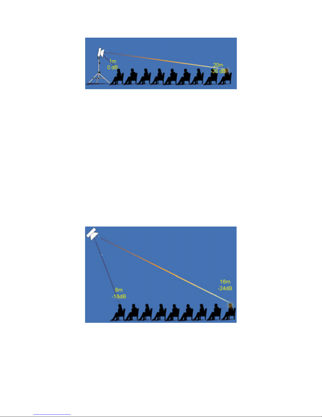
Figure 2a. A traditional speaker producing spherical waves and
mounted at ear height in the front of the room results in a 26dB
difference in direct field level when the distance ratio of near to far is
1:20. A listener in the back would report the loudness to be four or
more times softer than the front.
Thus while localization is good because the speaker is placed close to the visual activity,
the system does poorly in creating the desired sound level in the audience area. No matter
what volume setting is used, the sound is either too loud or too soft in most of the audience
area – it is simply impossible to establish the correct level for the audience with such a big
difference from front to back.
To achieve less variation in speaker-to-listener distances, and therefore less variation in
sound level, the speaker can be hung in the air and tilted down at the audience as shown in
Figure 2b. This is what is referred to unofficially as the ‘hang-and-tilt’ approach. The ratio in
this example is 2:1, corresponding to a sound level variation of only 6 dB. The hang-and-tilt
approach largely solves the level variation problem, which is why it was vigorously pursued
as a way to satisfy customer requirements.
Figure 2b. When the same speaker is mounted in the air and tilted
down, the level variation is reduced significantly – in this case to only 6
dB – which corresponds to a near-to-far distance ratio of 1:2.
Bose® MA12™ Modular Array: Technical Foundation & Discussion
April 2002, © Bose Corporation, All Rights Reserved
Page 7 of 36
Page 8

Of course, as with any engineering solution, the hang-and-tilt approach is not perfect. It has
its strengths and weaknesses as they relate to the goal of cost effectively satisfying the major
customer requirements. The details of these strengths and weaknesses are the subject of the
next section.
Strengths of the hang-and-tilt approach
THE strengths of a good hang-and-tilt system are that with it, excellent tonal balance,
consistent sound level, and speech intelligibility can be achieved. Moreover, because the
speakers are located up and out of the way, they rarely interfere with sightlines.
Over the years, Bose and others have developed a number of technological solutions
specifically designed to improve the quality of hang-and-tilt systems. For example, Panaray
®
LT speakers are designed with very narrow sound radiation patterns so that designers can
carefully aim them only onto audience areas and avoid reflective walls and ceilings that can
produce the excessive reverberation responsible for diminished speech intelligibility. These
speakers also exhibit a very sharp rolloff of sound outside their primary radiation angles,
making it easier to combine two or more in such a way that they exhibit a minimum of the
inter-speaker interference that can lead to dropouts in sound.
Similarly, the Bose Panaray 502
®
A loudspeaker represents an important contribution to the
field of hang-and-tilt speakers because it delivers consistent coverage over substantially a full
range of frequencies using very natural sounding cone-type drivers in a very small package.
This speaker is used in literally thousands of venues around the world where customers say it
meets their needs elegantly and unobtrusively.
As a final example of the types of innovations that have led to better hang-and-tilt systems,
until very recently it was thought to be difficult or impossible to include control of the lower
frequencies in hang-and-tilt designs. This lack of control meant that bass sound waves were
more or less allowed to go anywhere within a venue, causing a lack of clarity in music and
some masking of speech (and therefore a reduction of speech intelligibility). Today solutions
exist to control bass frequencies in hang-and-tilt designs with very nearly the same degree of
precision as the higher frequencies, including a comprehensive technique developed by Bose.
These solutions, which employ advanced array theory, have led to noticeable improvements
in the sound quality of systems in which they have been used.
Weaknesses of the hang-and-tilt approach
THE hang-and-tilt approach also has some weaknesses. For example, the designer must
ensure that the sound radiation pattern from the speaker being considered is appropriate for
the purpose of covering the audience area. However, the choice of speakers is limited to only
a few, which differ according to their radiation patterns. It is purely coincidence and therefore
rare for the designer to find a perfect match between the available radiation patterns and the
audience area. In general, the speaker being considered will have more or less coverage than
what is needed.
Bose® MA12™ Modular Array: Technical Foundation & Discussion
April 2002, © Bose Corporation, All Rights Reserved
Page 8 of 36
Page 9
If the speaker’s radiation pattern is too wide for the audience, there is over-coverage as
shown in Figure 3a. In these situations, sound radiates to areas other than the audience where
it reflects off of surfaces and arrives at the ears of the listeners as reverberation, which causes
degradation in clarity and intelligibility.
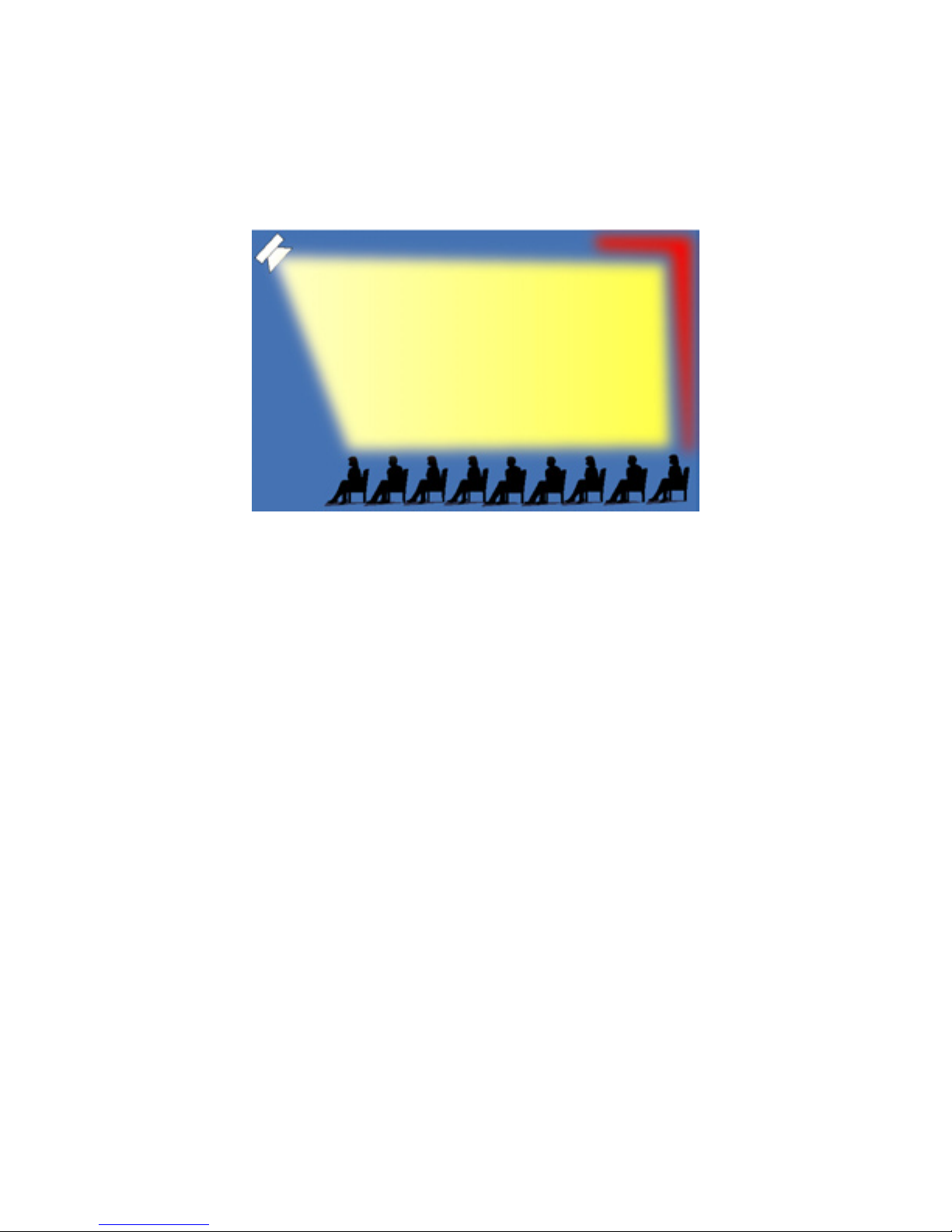
Figure 3a. The effect of choosing a speaker with a radiation pattern
wider than the audience is shown. Sound striking surfaces other than
the audience causes unwanted reverberation and reduced musical
clarity and speech intelligibility.
If, on the other hand, the speaker’s radiation pattern is too narrow for the audience, as
shown in Figure 3b, people outside the main beam will hear a serious degradation in tonal
balance, level and clarity.
Bose® MA12™ Modular Array: Technical Foundation & Discussion
April 2002, © Bose Corporation, All Rights Reserved
Page 9 of 36
Page 10
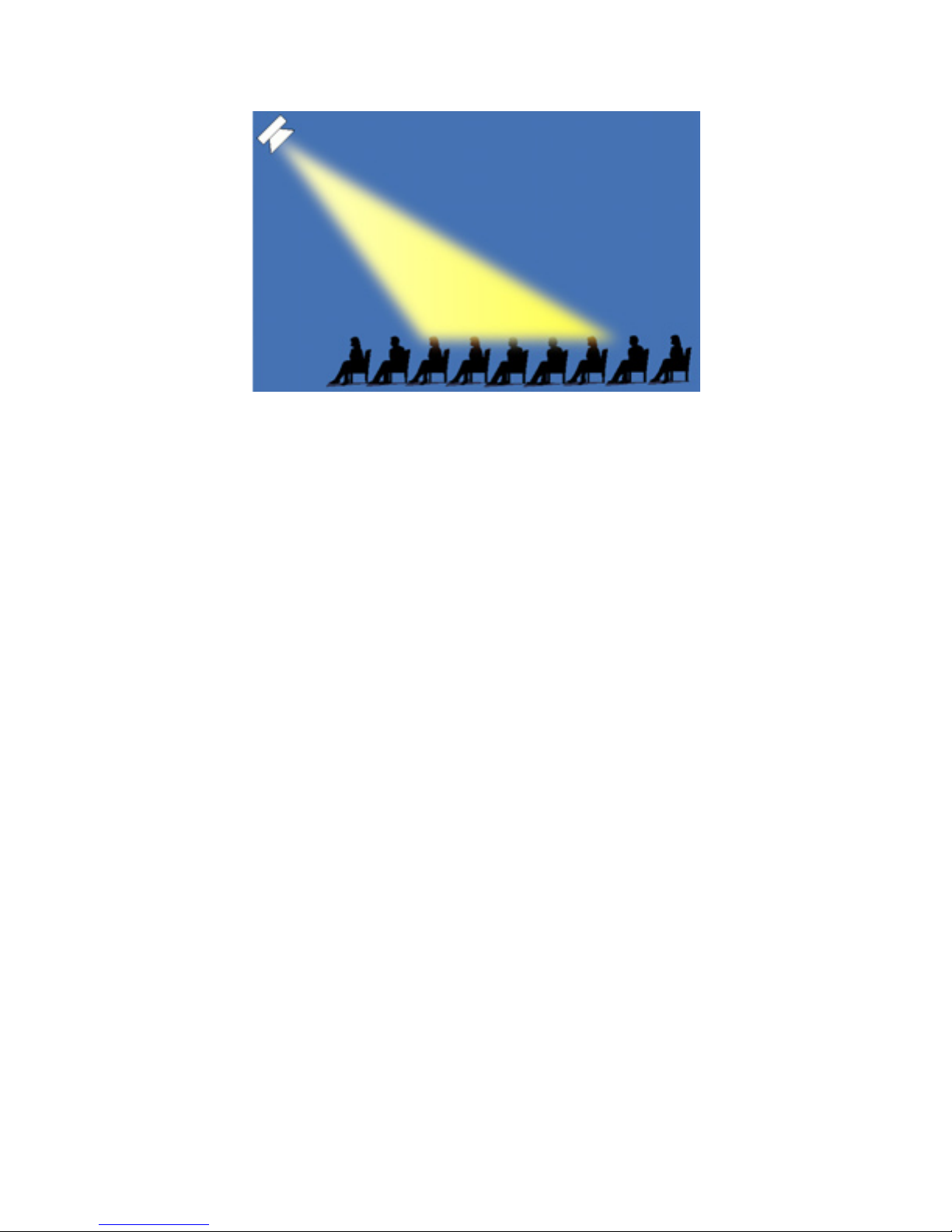
Figure 3b. The effect of choosing a speaker with a radiation pattern
narrower than the audience is shown. People outside the main beam get
poor sound quality.
In situations where the radiation pattern from a single speaker is too narrow, another
speaker is usually added. When that is done, however, the same set of challenges is repeated.
Will the added speaker be able to just cover the area that was uncovered before? If it does, it
is coincidental. In general, the added speaker will again have coverage that is too wide or too
narrow.
Regardless, when two or more speakers are used to cover an audience area, their individual
radiation patterns must be overlapped in order to avoid a coverage hole between their
patterns. This interference zone, shown graphically in Figure 4, can result in significant and
audible dropouts of sound at some frequencies. Without careful selection of speakers, their
locations, and aiming angles within a cluster, there can be as much as 20-30 dB of energy
missing in the middle of the frequency range crucial for speech. These dropouts caused by
interference have a significant impact on clarity, intelligibility and tonal balance.
Bose® MA12™ Modular Array: Technical Foundation & Discussion
April 2002, © Bose Corporation, All Rights Reserved
Page 10 of 36
Page 11
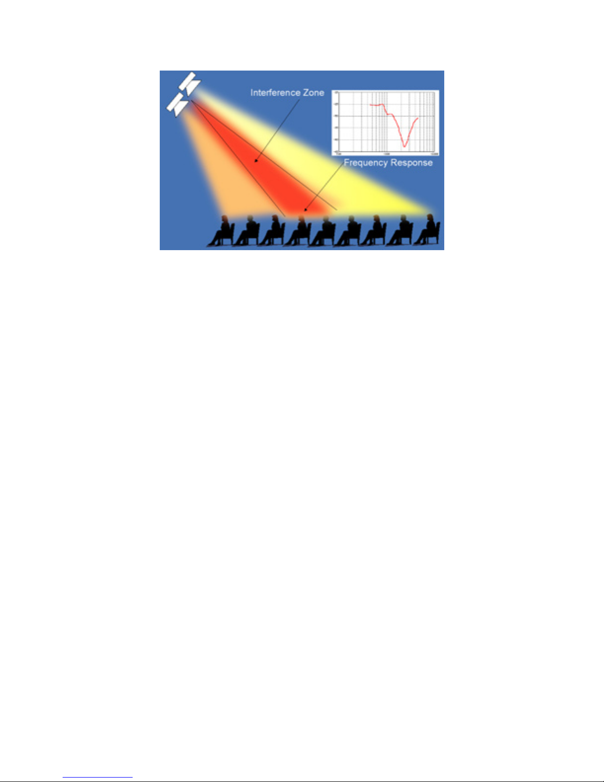
Figure 4. The interference zone caused by the overlap of two speakers
is shown. Inter-speaker interference can result in major sound dropouts
– as severe as 20-30 dB – which harms tonal balance, clarity, and
intelligibility.
For these reasons and others, hang-and-tilt systems require a significant investment in
design time to achieve good coverage without excessive interference. To aid in this effort, the
designs are usually created using computer modeling programs, where creating the room
model, then selecting, positioning, and aiming speakers, and optimizing the design can take
anywhere from a day to weeks, or even months in the case of large projects.
Once designed, sophisticated rigging is often needed to ensure that the speakers are
properly and attractively installed. A professional engineer is often employed to implement
the exact aiming angles dictated by the design and to ensure mechanical integrity and safety.
Then the rigging hardware has to be purchased or fabricated and shipped to the site. The
installation requires a lift or scaffolding to hang the speakers in the right place. And finally
the installation often has to be reviewed by the local engineer to ensure that it meets code and
safety requirements. Rigging and installation costs can climb into the thousands of dollars.
Once the system is installed, another significant investment in engineering time is required
for system tuning and adjustment. Level matching the low to the mid and high frequencies
and setting time delays in a cluster takes time and requires a skilled field engineer. So does
setting time delays and matching levels from cluster to cluster and deciding on the overall
room equalization.
Thus designing, installing, and tuning a hang-and tilt design is time consuming and requires
a high level of skill in a variety of areas. These factors mean that hang-and-tilt systems are
often expensive to create.
Hang-and-tilt systems also suffer from compromised performance in the area of sound
localization. The visual activity is usually to the front of the listener, but the sound comes
from above where the speakers are located. This lack of eye-ear correspondence is
Bose® MA12™ Modular Array: Technical Foundation & Discussion
April 2002, © Bose Corporation, All Rights Reserved
Page 11 of 36
Page 12

disconcerting and creates an ongoing distraction. When given the choice, listeners prefer the
sound to come from the same direction as the action.
And finally, service and maintenance is difficult when speakers are hanging in the air.
Service usually requires that the floor area be cleared, and a lift or scaffolding employed.
This is in general inconvenient and expensive. Sometimes, a facility has to be closed for a
day or more in order to gain access to the speakers, or the work must take place late at night
when labor costs can be much higher.
Summary
IN summary, the hang and tilt method is effective in meeting customer requirements. But not
without some compromises in sound quality, usually due to reduced performance in the
overlap areas of speakers and in poor localization performance. Perhaps more important, the
process of creating and servicing a system is time consuming and requires a high level of
skill in a number of areas, both of which add significantly to the cost of these systems.
Can anything be done about these weaknesses? Or should we only look forward to more
incremental improvements to the hang-and-tilt approach – a new speaker with slightly better
radiation pattern control, or equivalent performance in a somewhat smaller package, or
somewhat easier rigging hardware, for example?
We believe there is a true extension to hang-and-tilt components – a tool for designers that
can often overcome the weaknesses that have been described. To explain why we have come
to this conclusion, we must return to and examine the fundamental assumption that originally
led the industry to the hang-and-tilt approach.
Bose® MA12™ Modular Array: Technical Foundation & Discussion
April 2002, © Bose Corporation, All Rights Reserved
Page 12 of 36
Page 13

THREE KINDS OF SOURCES
AS explained, the hang-and-tilt approach evolved because of a fundamental property of the
speakers used. Namely, the speakers have sound waves that radiate in all directions, in and
out, up and down, left and right. And that means that the intensity of sound leaving the
sources falls off by 6 dB per doubling of distance. We call these spherical-wave sources. To
provide consistent sound levels over a widely distributed audience, listeners must be nearly
equidistant to the speaker, and hence the need to raise the speaker into the air over the heads
of the listeners.
The obvious question is whether this fundamental 6 dB per doubling of distance property is
true for all sources. The answer is no. There are other kinds of sources that produce different
kinds of sound waves with very different behavior.
Plane waves
FOR example, we generate plane waves to measure the performance of compression drivers
in the lab. These waves diverge in only one dimension: out, but not up and down or left and
right. As a result, the intensity of a plane wave does not fall off at all with distance
in Figure 5. In other words, the distance can be doubled and the sound level is the same. Such
a source, therefore, could produce the same sound pressure level in all seats – what would be
considered ideal coverage.
1
, as shown
1
This is an ideal description. In reality, any sound wave, whether spherical or planar, is affected by
environmental effects, such as humidity, temperature and wind.
Bose® MA12™ Modular Array: Technical Foundation & Discussion
April 2002, © Bose Corporation, All Rights Reserved
Page 13 of 36
Page 14

Figure 5. A plane wave diverges in only one dimension: out, but not up
and down, or left and right. As a result, the intensity does not drop off
at all.
Plane waves, however, are difficult and impractical to create outside of the laboratory. To
create plane waves in the open air requires an unusually large surface area – one at least one
meter by one meter square – to have any chance of creating plane or plane-like waves over a
reasonably wide range of frequencies. And by unique mechanical inventions this source
would have to be pistonic, meaning that the whole surface moved at the same magnitude and
phase at all times. To our knowledge, no such source has been attempted much less achieved,
even in prototype form.
Yet even if such a source could be realized – and if it were only driven at frequencies
where the wavelength is much smaller than its dimensions – there would be no sound outside
the source area, as shown in Figure 6, because the plane, or plane-like waves are only
radiated out but not to the sides, or up or down. A one-meter by one-meter source, therefore,
would have extremely limited, if any, application because it would only cover listeners
located within a one-meter by one-meter projection. To cover a typical audience, a plane
wave source would have to be much larger. It would need to be the same width and height as
the audience. Even if mechanically possible, which is extremely unlikely, it would obviously
also be completely impractical because of its size.
Bose® MA12™ Modular Array: Technical Foundation & Discussion
April 2002, © Bose Corporation, All Rights Reserved
Page 14 of 36
Page 15

Figure 6. What makes plane waves impractical is the fact that there is
no sound outside the physical size of the source.
Cylindrical waves
AT this point, two kinds of waves have been described: spherical waves that radiate in three
dimensions and whose intensity drops off by 6 dB per doubling of distance, and plane waves
that radiate in one dimension and fall off by 0 dB per doubling of distance. A natural question
is, therefore: “Is there a third kind of wave that radiates in two dimensions and falls of
somewhere between 0 and 6 dB per doubling of distance?” The answer is yes. And these are
called cylindrical waves. To understand their behavior, it is helpful to return to the one-meter
by one-meter source that created plane waves. Looking down on the plane-wave source, it is
clear that the sound is confined to the width of the source (Figure 7, top right). Looking from
the side of the source, the sound is similarly confined to the height of the source (Figure 7,
bottom right).
Bose® MA12™ Modular Array: Technical Foundation & Discussion
April 2002, © Bose Corporation, All Rights Reserved
Page 15 of 36
Page 16

Figure 7. As we look down on the plane-wave source, we see that the
sound is confined to the width of the source (top right). If we look from
the side, the sound is confined to the height of the source (bottom
right).
Again looking down on the source, now imagine that the horizontal dimension of the
source (currently one meter) was reduced to only a few centimeters. The result is shown in
Figure 8. The vertical radiation pattern does not change because the source retains the same
vertical dimension (bottom of figure). The horizontal radiation pattern (top of figure) changes
drastically because the much smaller source size corresponds to a much wider radiation
pattern. (Note that the same physics explain why a 2" (5 cm) driver has a much wider
radiation angle than a 12" (31 cm) driver, assuming both are operating at the same
frequency).
Bose® MA12™ Modular Array: Technical Foundation & Discussion
April 2002, © Bose Corporation, All Rights Reserved
Page 16 of 36
Page 17

Figure 8. If we reduce the horizontal dimension of the source, the
radiation pattern gets wider and starts to spread out (top). The vertical
radiation pattern does not change because the vertical dimension of the
source has not changed (bottom).
If the horizontal and vertical radiation patterns of Figure 8 are combined into a threedimensional radiation pattern, the result is waves that are cylindrical in shape. To be more
exact, the radiation pattern is wedge-shaped, or like a piece of a cylinder, as shown in
Figure 9. The shape of the source responsible for this wedge-shaped pattern is slim and long:
in other words, it is line shaped. Thus a line-shaped source where all parts of the line move
with equal magnitude and phase produces a wedge-shaped radiation pattern. The sound
radiates in and out and to the sides, but not up and down.
Bose® MA12™ Modular Array: Technical Foundation & Discussion
April 2002, © Bose Corporation, All Rights Reserved
Page 17 of 36
Page 18

Figure 9. The radiation pattern of a long, thin source is wedge-shaped.
The sound radiates in two dimensions: in and out and left and right, but
not up and down.
How does sound intensity fall off as a function of distance for such sources and such
waves? The answer lies halfway between spherical waves and plane waves, as shown in
Figure 10. The spherical source radiates in three dimensions and falls off as 6 dB per
doubling of distance, the cylindrical wave radiates in two dimensions and falls off as 3 dB
per doubling of distance, and the plane wave radiates in one dimension and falls of as 0 dB
per doubling of distance.
2
2
For the reader interested in understanding the underlying physics of these differences, imagine a sound-
intensity-meter ten feet in front of a source producing each kind of wave: spherical, planar, and
cylindrical. Furthermore, imagine that at this distance, each source produces the same level. Now,
consider a small area of the sound wave at the location of the meter.
- As the spherical wave spreads out, the wave must expand over the surface of a sphere. When the sphere
doubles in diameter, the small area of the sound wave must expand over a proportionately larger area at
the doubled distance. As a result, the intensity of the original area of sound diminishes. Since the area of
a sphere increases as the square of the radius, increasing the distance from the source by a factor of two
(doubling the distance and therefore the radius) means reducing the sound intensity by a factor of four
(two squared). A factor of four in sound intensity corresponds to 6 dB.
- As the cylindrical wave spreads out, the wave must expand over the surface of a cylinder. When the
cylinder doubles in diameter, the small area of the sound wave at the closer distance must spread over a
proportionately larger area at the doubled distance. As a result the intensity of the original area of sound
wave is reduced. Since the area of a cylinder increases proportionately with only the radius (rather than
as the square of the radius as in the case of a sphere), increasing the distance from the source by a factor
of two (doubling the radius) means reducing the sound intensity by only a factor of two. A factor of two
in sound intensity corresponds to 3 dB.
- As the plane wave progresses, the wave does not expand. When the wave reaches a distance that is
double the original, the small area of the sound wave at the closer distance has not spread at all, and as a
result the intensity of the original piece of sound wave is the same. A factor of zero in sound intensity
corresponds to 0 dB.
Bose® MA12™ Modular Array: Technical Foundation & Discussion
April 2002, © Bose Corporation, All Rights Reserved
Page 18 of 36
Page 19

Figure 10. The intensity of a spherical wave falls off by 6 dB per
doubling of distance, a cylindrical wave by 3 dB, and a plane wave by
0 dB per doubling.
(For completeness, it is important to note that only a line source that is infinitely long,
perfectly thin, and equal in magnitude and phase at all points along the line will produce a
cylindrically shaped wave for all frequencies and all distances. However, the behavior of
even a one-meter line source can be better described using the basic properties of cylindrical
waves than by any other means considered.)
Bose® MA12™ Modular Array: Technical Foundation & Discussion
April 2002, © Bose Corporation, All Rights Reserved
Page 19 of 36
Page 20

APPLYING LINE SOURCES TO SOUND SYSTEM DESIGN
THE 3 dB per doubling behavior of cylindrical waves is of special interest in sound system
design because it is so much more gradual than the 6 dB per doubling behavior that
motivated us to hang and tilt speakers. On the other hand, so was the 0 dB per doubling
behavior of plane waves, but unfortunately, producing them was impractical in real life. Is it
more practical to produce cylindrical waves? Or are there problems that will rule this out too?
If such a source can be realized, would it really do a good job at meeting customer
requirements?
Source shape and sound output capability
TO begin, a source that produces cylindrical waves does not have to be rejected for the same
reasons a plane-wave source was rejected. A cylindrical-wave source must be as tall as the
audience, but not as wide, since the wide horizontal radiation pattern can be relied on to
cover an audience distributed side to side; a tall, slim source, resulting in wide side-to-side
radiation, can cover a typical audience.
Second, with modern transducer technology, there is no reason that a line source can not
produce a balanced frequency response at the kind of output levels required in many
applications. Major improvements in transducer technology (including many introduced by
Bose) mean that it is no longer true that the small transducers needed to fit into a slim lineshaped source lack the correct balance of frequencies or necessary output capacity. A full,
balanced frequency response and very high output is now possible from speakers no larger
that a tea cup. Therefore, concerns about frequency response and output are also not reasons
to reject the line source.
Meeting the primary customer requirements
IN principal – in other words without regard to the specifics of any particular implementation
– would a line-shaped source radiating cylindrical or near-cylindrical waves be a good choice
for meeting the major customer requirements listed earlier?
Re-examination of the side view of the radiation pattern of a line source, shown in Figure
11, reveals that sound does not radiate up and down, but rather is confined to a region
between a plane perpendicular to the top of the array and one perpendicular to the bottom.
When such a source is placed in a room, it means that sound will not radiate up and down and
therefore will not radiate to the ceiling and upper walls, where reflections contribute to the
amount of reverberation and therefore to the degradation of music clarity and speech
intelligibility. Such a source would be therefore ideally suited to environments with longer
reverberation times such as churches, auditoriums, airports, hallways and so on.
Bose® MA12™ Modular Array: Technical Foundation & Discussion
April 2002, © Bose Corporation, All Rights Reserved
Page 20 of 36
Page 21

Figure 11. In a side view, the sound radiation is limited to a region
between a plane perpendicular to the top of the array and one
perpendicular to the bottom of the array. The sound does not radiate up
to the ceiling and upper walls where reflections cause more
reverberation and lower intelligibility.
Next, consider the fact that the intensity falls off much more gently with distance than a
conventional spherical-wave speaker. This means the source can be placed in locations where
a conventional source would produce far too much level variation in the audience. A line
source placed at ear height maintains a relatively consistent level throughout the audience
area. Variations in level have not been completely eliminated, but the drop off of level with
distance is perceived as modest over a very large audience area.
Consider the amount of engineering effort needed to create a system using line sources.
Design would be radically simplified, because it reduces to ensuring that the audience is
within the wedge-shaped radiation pattern. To do this almost always means locating the line
source along a wall at ear height. None of the effort needed in a traditional hang-and-tilt
design to carefully select, locate, and aim speakers, or to design multi-speaker clusters, is
involved. Nor is the need to design complicated and expensive rigging. Or to undertake
expensive installation work. After-installation tuning time is reduced because line sources are
not used in clusters, and service is drastically simplified because the speakers are located at
ear level and are therefore easily accessed.
Furthermore, a line source can be as slim as a few inches so that when it is mounted to a
wall, it can virtually disappear. There are no speakers hanging from the ceiling and no
awkward clusters to hide. In many situations, this represents a major improvement in the
physical impact imposed by a sound system on its environment.
Bose® MA12™ Modular Array: Technical Foundation & Discussion
April 2002, © Bose Corporation, All Rights Reserved
Page 21 of 36
Page 22

Thus a line-shaped source has the potential to satisfy all of the major customer
requirements in ways that often overcome some of the weaknesses of the hang-and-tilt
approach. As such, a well-executed line-shaped source would not be simply an incremental
improvement to the well-worn products and techniques used in hang-and-tilt designs. It
would represent an important new tool that would significantly increase the options designers
have in many venues. The potential would exist to satisfy the basic customer requirements
and to do so in many cases at substantially less cost. Such a source would therefore represent
something more significant than an incremental advancement. The remainder of this
document is devoted to providing evidence that such an advancement has been made.
BOSE MA12™ MODULAR ARRAY
THE Bose MA12 array is a one-meter tall speaker module consisting of twelve closely-spaced
high-output 2.2" (6 cm) drivers operating over the frequency range from 120 Hz to 16 kHz. A
one-meter module was chosen because it is tall enough to produce the desired wedge-shaped
radiation pattern, short enough to be easily handled, and modular so that longer line sources
can easily be constructed.
In the MA12, the drivers chosen exhibit pistonic behavior up to higher frequencies than
what could be achieved with larger drivers of similar quality, a desirable feature when the
goal is to create the wedge-shaped pattern over a very wide range of frequencies.
The small driver diameter was also chosen so that the source would have very wide
horizontal dispersion. The
MA12 has 160° of coverage up to very high frequencies. This is
important because when the audience is close – a definite possibility because the gentle
change in level with distance means it is not too loud close to the speaker – it tends also to be
distributed over a wide angle.
The ultra-slim profile of the
MA12, also a consequence of the driver chosen, means that the
speaker blends into almost any environment. A single array module has a surprising heightto-width aspect ratio of 12:1. If two modules are used, this increases to 24:1. Taken together
with the fact that the speaker is available in black and white and can also be easily painted,
we believe it is fair to say that it will virtually disappear into most rooms.
Bose® MA12™ Modular Array: Technical Foundation & Discussion
April 2002, © Bose Corporation, All Rights Reserved
Page 22 of 36
Page 23

OTHER LINE-SHAPED SOURCES
IN the last section, the unique decisions and choices Bose made in designing the innovative
MA12™ modular array were discussed. However, there are other line-shaped sources already
available. How do they compare to the
Column speakers
SOME line-shaped sources have been around for a long time. A number of well-known
manufacturers have developed versions, called column speakers, as early as the 1940’s. The
speakers had limited frequency response and output. In other applications where better tonal
balance and higher levels were needed they simply could not be met by these column
speakers. None could be considered high performance speakers by today’s standards.
Sources using electrostatic, ribbon, or planar magnetic transducers
ANOTHER class of line-shaped speakers uses electrostatic, ribbon or planar magnetic
transducers. In general, these transducers do not produce a full-range frequency response, but
only covers from about 3-500Hz and up. To cover the range of lower frequencies up to about
300-500Hz, the transducers are augmented by traditional sources typically using woofers in a
sealed enclosure at the bottom of each speaker.
In some implementations, the ribbon emits sound both to the front and the back, so highenergy sound from the rear of the speaker is directed away from the audience and onto wall
surfaces where reflections add to reverberation and degrade clarity and intelligibility. Many
of these speakers, while looking promising on paper, are not designed for professional
applications, require a base to extend the frequency response, and radiate equal amounts of
sound to the rear.
MA12?
DSP-based arrays
THERE IS another class of arrays that are using digital signal processing (DSP) to control and
steer the speakers’ radiation patterns. Most of these arrays use 4" (10.2 cm) or larger
transducers. The drivers are either spaced closely in a line, or in a scheme where spacing
varies. The speakers have built in multi-channel signal processing and amplification.
There are some obvious differences between these arrays and the
speakers are using larger drivers resulting in an appearance that is significantly wider than the
MA12. The larger drivers also have narrower horizontal coverage, which can be a
disadvantage with audiences located close to the speaker.
The biggest difference is these speakers’ use of
array, and which also makes the cost much higher than the
DSP to control the radiation pattern of the
MA12. Drivers get different
signals and hence require their own signal processing and amplification. This makes it
possible to steer the radiation pattern at middle and higher frequencies. For example, the
Bose® MA12™ Modular Array: Technical Foundation & Discussion
April 2002, © Bose Corporation, All Rights Reserved
Page 23 of 36
MA12. First, these
Page 24

speaker can be mounted high on a wall and the radiation pattern steered down to the audience
area on the floor.
Why did Bose elect not to use
DSP in the MA12™ Modular Array? First, in our solution we
sought a pure wedge-shaped radiation pattern, not a variety of different, selectable radiation
patterns. We did this so that we could cover a large audience area from a speaker located at
ear height. For this, no
DSP is needed and thus none is used. Second, if a speaker positioned
high in the air is needed, then this seems to us an ideal application for traditional hang-andtilt speakers, which have shown in countless facilities to meet basic customer requirements at
a fraction of the cost of using many channels of
DSP and amplification to achieve the same
effect.
High-output arrays for touring systems
THERE is a class of speakers that use much larger and more powerful transducers in much
larger enclosures than what is used in the
and more expensive than the
MA12. As a result– in addition to the differences in transducer
complements - the most important difference between these speakers and the
MA12. As a result, these speakers are much larger,
MA12 is the
markets for which they are intended. They are very clearly aimed at large touring sound
systems for musical groups playing in stadia and arenas. The
MA12 is aimed at the heart of
the installed sound market. While philosophically similar, these products are far too large, far
too powerful, and far too expensive for our target markets.
Column like speakers
THE last category is speakers that look like line arrays but really are not. They are really
spherical-wave sources housed in line-shaped enclosures. This is not to say that the
manufacturers are making false claims, but merely to note that a line-shaped source may not
house an acoustical design intended to behave like the line sources we have discussed here.
An example of these speakers uses four 4" (10.2 cm) drivers and three tweeters in a line.
This design and others like it, while having features that can have advantages in certain
applications, do not attempt to achieve pistonic behavior over the length of the line and over
a wide range of frequencies. The four drivers in this configuration could be too widely spaced
for this purpose, for example. Similarly the tweeter array in the middle may not be tall
enough to produce a wedge-shaped radiation pattern at the lower part of its frequency range;
the array is simply not tall enough, and the drivers not densely- packed enough. These
speakers behave more like conventional loudspeakers, albeit with narrower vertical radiation
patterns.
Bose® MA12™ Modular Array: Technical Foundation & Discussion
April 2002, © Bose Corporation, All Rights Reserved
Page 24 of 36
Page 25

Summary
IN none of the existing approaches have the inventors taken the same design approaches as
Bose in the case of the
MA12™ array. The goals in creating the MA12 were exceptionally
high acoustic output from an ultra-thin baffle area, a wedge-shaped radiation pattern and
gentle fall off of sound characteristic of cylindrical waves, and wide horizontal dispersion in
a lightweight, modular, architecturally unobtrusive, and affordable package. It is our belief
that we have succeeded in this regard. However, we welcome the fact that designers and
customers alike will be able to judge for themselves the degree to which they agree with our
claims. We recognize that the success of the design depends on their judgement, not ours.
DESIGNING WITH THE MA12
IN this section, some of the basic rules for applying the MA12 are presented. These rules are
intuitive given the wedge-shaped radiation pattern of this speaker. For a listener to be
covered with sound from a source with a wedge-shaped radiation pattern, his or her ears must
be contained between two imaginary 160° wedge-shaped surfaces, one extending from the
top of the speaker, and the other extending from the bottom.
To cover a large flat audience area with sound, a single
MA12 module is placed as shown
in Figure 12. It is located so that the bottom of the array is about at the height of the chest of
a person seated in the first row. Oth er modules may be added if necessary until the top of the
array covers the head of a listener in the last row. (In the figure, only one module is used.)
Bose® MA12™ Modular Array: Technical Foundation & Discussion
April 2002, © Bose Corporation, All Rights Reserved
Page 25 of 36
Page 26

Figure 12. To cover a large flat audience area with sound, add a single
MA12™ array module. Locate it so that the bottom of the array is
about at the height of the chest of a person seated in the first row.
Check that the highest listener is not above the top of the speaker. If he
is, add another module to extend the length of the source.
To cover a sloped audience area there are two options: a taller array can be constructed, as
shown in Figure 13, or the array can be tilted to the same angle as the seating (not shown).
Again, the bottom of the array should be at the chest height of the listener in the first row,
and the top of the array should be taller than the ear height of a person standing in the last
row.
Bose® MA12™ Modular Array: Technical Foundation & Discussion
April 2002, © Bose Corporation, All Rights Reserved
Page 26 of 36
Page 27

Figure 13. To cover a sloped audience area, build a tall array so that the
bottom of the array is at the chest height of the listener in the first row,
and the top of the array is taller than the ear height of a person standing
in the last row. Alternatively, a module can be tilted to the same angle
as the seating (not shown).
To cover a balcony there are two options: a decentralized approach as shown in Figure 14,
where the
MA12™ speaker is located in the front to cover the main floor and another on delay
is used to cover the balcony. The other approach is shown in Figure 15, where everything is
covered from the front.
Bose® MA12™ Modular Array: Technical Foundation & Discussion
April 2002, © Bose Corporation, All Rights Reserved
Page 27 of 36
Page 28

Figure 14. Covering a balcony using a decentralized approach is
shown: an MA12™ speaker for the main floor and a delay speaker for
the balcony on delay.
Figure 15. Alternatively, the balcony can also be covered from the
front.
Bose® MA12™ Modular Array: Technical Foundation & Discussion
April 2002, © Bose Corporation, All Rights Reserved
Page 28 of 36
Page 29

SAMPLE PROJECTS
IN the end, what convinced Bose to develop the MA12™ speaker was the enthusiastic
feedback we received from many of our field engineers around the world whom for several
years had been designing and installing custom line arrays. What are now obvious
applications for the
nightclubs, performing arts centers, restaurants, retail outlets, conference centers, and
transportation buildings – were all tested by field engineers using custom arrays. It is
instructive to examine some of these projects as they clearly convey the breadth of
applications for these sources, and help support the basic conclusions of this document. It
should be noted that if any of these projects were undertaken today, they would be designed
with the
MA12.
Saint Peters Basilica, Vatican City (Rome, Italy)
EVERY 25 years, the Catholic world celebrates an ancient tradition called the Holy Year (also
called the Jubilee Year). To prepare for the year 2,000 Holy Year, the sound system for Saint
Peter’s Cathedral in Rome was upgraded. St. Peter’s, shown in Figure 16, is the most famous
church for people of the Catholic faith.
MA12 – places of worship, pedestrian concourses, auditoriums,
Originally, consultants on this project recommended two systems: one for voice and a
second for music. They argued that due to poor acoustics attributed to the huge dome and
exceptionally long reverberation times (about 20 seconds in the speech range) it was
impossible to design one system optimized for both speech and music. Giorgio Gianotto,
Bose® MA12™ Modular Array: Technical Foundation & Discussion
April 2002, © Bose Corporation, All Rights Reserved
Figure 16. St. Peter’s Basilica, Vatican City.
Page 29 of 36
Page 30

Bose’s Technical Director in Italy, was able to prove using Bose Modeler® and Auditioner
that one system could perform both functions, a tremendous savings for the Vatican.
He used seven Bose Model 25s to create a custom line array. Fifty-six of these arrays were
placed at speaker locations allowed by the Vatican. One of the arrays is shown in Figure 17.
The design was presented with Auditioner and in early 1999 Bose was awarded the project.
During the month of June the system was installed.
®
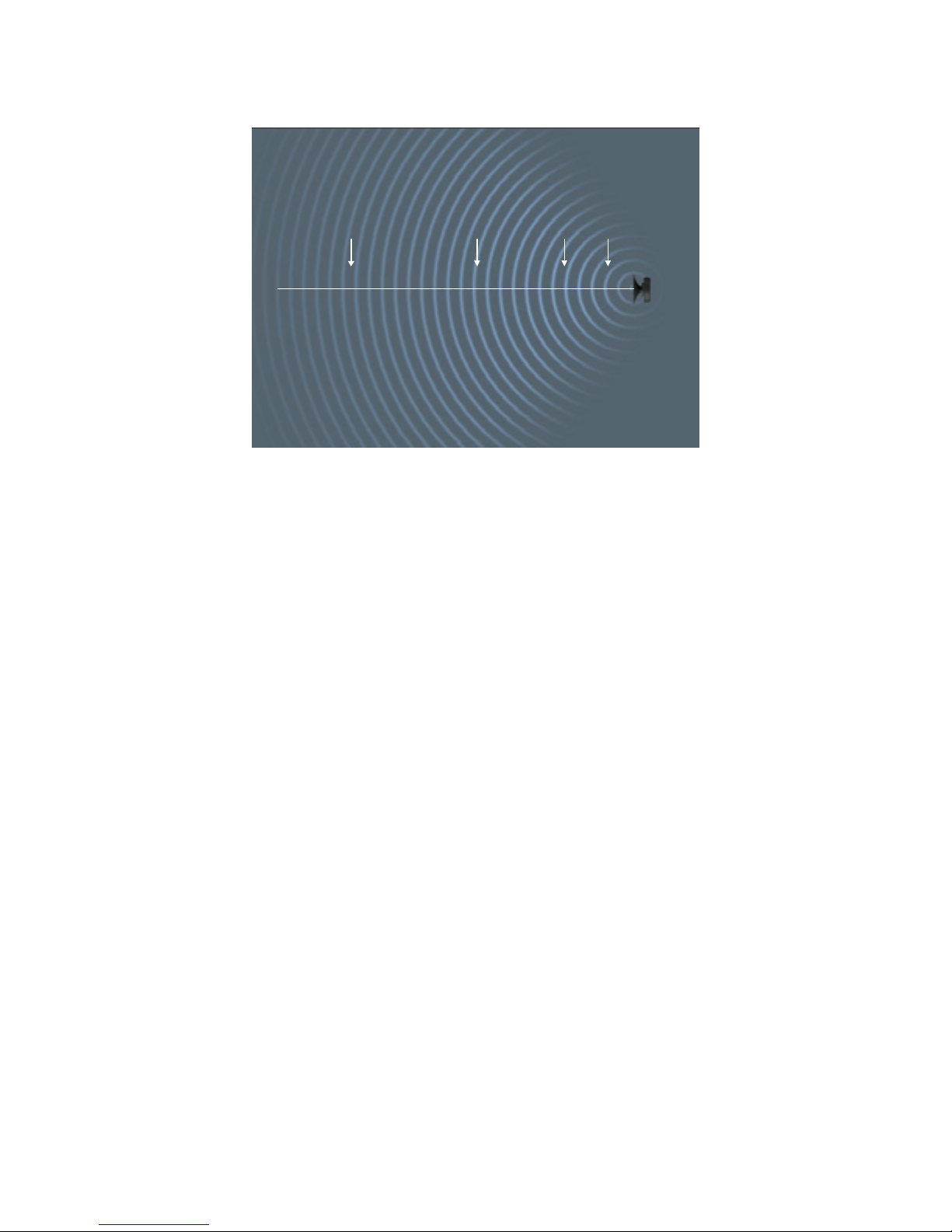
Figure 17. One of the custom made line arrays used in St. Peter’s
Basilica is shown (arrow).
On midnight of December 24, 1999, Mr. Gianotto wrote, “When the notes of the big
musical horns and the silky music of string instruments mixed with the Pope’s voice
officially inaugurating the new Holy Year, a miracle happened under the sky of Rome. For
the first time in history every single one of the faithful in each part of the Basilica could
clearly understand every spoken word. And they could enjoy the clarity and full, balanced
tone of the music.” Today, the system is considered the reference for audio in places of
worship in Italy. So far fourteen projects have been completed with line arrays in Italy, each
we are told with similar success.
Perhaps most important from a technical perspective on this project was the controlled
vertical dispersion of line arrays. In spite of major doubts expressed by the Vatican’s
consultants, the Bose line arrays eliminated the reverberation caused by sound reflecting off
the ceiling and huge dome structure.
Bose® MA12™ Modular Array: Technical Foundation & Discussion
April 2002, © Bose Corporation, All Rights Reserved
Page 30 of 36
Page 31

Holy Mosque, Makkah, Saudi Arabia
BOSE line arrays are also used in the Holy Mosque in Makkah, Saudi Arabia, Islam’s
holiest shrine. During important religious events, the mosque holds about two million people.
An aerial view during one of the high holidays is shown in Figure 18.
Figure 18. The Holy Makkah Haram in Saudi Arabia. On holy days, up
to two million worshipers are present.
One of the most challenging areas in the mosque is a 1,000-foot long (300 meter) corridor,
called the Massaa, which has a reverberation time of about seven seconds. A view of the
Massaa is shown in Figure 19.
Bose® MA12™ Modular Array: Technical Foundation & Discussion
April 2002, © Bose Corporation, All Rights Reserved
Page 31 of 36
Page 32

Figure 19. The Massaa area is a long corridor with a reverberation time
of about seven seconds. The existing system, along with a wide variety
of alternatives explored with Modeler and Auditioner, did nothing to
improve intelligibility. A line array solution was tried late in the
research phase of the project and proved stunningly effective.
The existing system used speakers in the ceiling with 4” (10.2 cm) drivers, laid out in rows
of 4, spaced every 5 meters. According to the occupants, the speech was completely
unintelligible. Many alternative design approaches were then tried by a research team at
Bose, using Modeler and Auditioner as their tools. Large-format horns in the ceiling,
carefully aimed at the floor were tried in an attempt to decrease the amount of reverberation;
Bose 402s were tried on the sidewalls; Model 32s at a low height so as to get them close to
the people was tried; FreeSpace 3 cubes in the same locations were tried. None of these
alternatives made a significant improvement on the intelligibility.
Then line arrays using twelve (12) 4.5” drivers mounted in three enclosures were tried. The
results stunned the research group. The fact that these line arrays do not emit sound up and
down caused the reverberant field to go down dramatically and the speech intelligibility to
increase significantly. A system has now been installed throughout the mosque. The customer
has told Bose that it is the Massaa where the largest improvement has been achieved.
Bose® MA12™ Modular Array: Technical Foundation & Discussion
April 2002, © Bose Corporation, All Rights Reserved
Page 32 of 36
Page 33

Auditorium in Japan
THE project is an auditorium in Japan that is designed for classical music concerts. But it is
also a public hall used for lectures and debates. In such rooms there is always tension
between the desire for the room to be dry enough to deliver clear and intelligible speech yet
reverberant enough to support classical music.
The auditorium holds about 800 people, and has a reverberation time of about two seconds.
It was the team’s job to design a system that would provide excellent intelligibility and also
reproduce music faithfully.
Figure 20. The line arrays are so well hidden in this facility they are
impossible to locate. (They are mounted to each side of the stage and
next to the pipe organ for the balcony as shown by the arrows.) In this
auditorium, both the unobtrusiveness and speech intelligibility
performance of the arrays made them a clear winner over a
conventional approach.
Using Modeler and Auditioner, a comparison was made between typical solutions for the
concert hall – a massive speaker array consisting of speakers located just below the ceiling –
and line arrays. The customer and architects clearly noticed the advantage of the line array.
They all noticed the improvement in speech intelligibility, and they all appreciated the
difference in visual impact: the line arrays disappeared whereas the conventional cluster
interfered with the natural beauty of the auditorium. The system was installed and the
performance determined to match what was heard through Auditioner.
Bose® MA12™ Modular Array: Technical Foundation & Discussion
April 2002, © Bose Corporation, All Rights Reserved
Page 33 of 36
Page 34

Lampertheim Church
THE town of Lampertheim is just outside the city of Frankfurt, Germany. The church in
Lampertheim had an outdated sound system and the customer was frustrated with the sound
quality. The church has a reverberation time of around four seconds. Thomas Steinbrecher, a
field engineer in the Bose Germany office, used Modeler and Auditioner to determine that a
line array approach would work best. Careful examination of Figure 21 will reveal the
locations of the line arrays he created. A close up of the array – made of sixteen Bose Model
101s – is shown in Figure 22.
Figure 21. The custom designed line arrays blend in nicely next to the
alter.
Bose® MA12™ Modular Array: Technical Foundation & Discussion
April 2002, © Bose Corporation, All Rights Reserved
Page 34 of 36
Page 35

Figure 22. A close up of the line array is shown. It is made from sixteen
Bose Model 101s.
The system is installed and the customer is very satisfied. The result is clear, natural and
intelligible sound, even though the room is very reverberant. And the arrays blend
unobtrusively into the architecture of the church. Our German colleagues say that the line
arrays are particularly insensitive to feedback, a problem the church was experiencing
regularly with their old system.
Bose® MA12™ Modular Array: Technical Foundation & Discussion
April 2002, © Bose Corporation, All Rights Reserved
Page 35 of 36
Page 36

CONCLUSION
FUNDAMENTAL assumptions about the behavior of loudspeakers led the professional sound
industry to use a single approach to sound system design for much of the past fifty years. The
hang-and-tilt approach, while effective in meeting most of the basic customer requirements,
is also an approach that requires an extensive engineering effort to do properly, is often
expensive to install, is invasive to the appearance of a facility, and is difficult to service.
Our intent has been to show that the fundamental assumption leading to hang-and-tilt as the
dominant approach is not true for all sound sources. And at least one of the alternatives – line
sources – has properties that address many of the weaknesses of the hang-and-tilt approach,
and are practical to build.
Bose has undertaken the development of such a source based on the extraordinary results
obtained with custom-made versions of line sources in a wide variety of facilities throughout
the world, including acoustically challenging facilities. The result is an unobtrusive, yet
acoustically powerful speaker that can be used to satisfy basic customer requirements in
many facilities and often at significantly less cost than a traditional hang-and-tilt system.
It is our belief that such a source is capable of significantly extending the options available
to sound designers, and as such represents an important extension to and enhancement of
what is currently possible.
Bose® MA12™ Modular Array: Technical Foundation & Discussion
April 2002, © Bose Corporation, All Rights Reserved
Page 36 of 36
 Loading...